EP4410438A1 - Kartuschensystem zur abgabe einer wässrigen lösung - Google Patents
Kartuschensystem zur abgabe einer wässrigen lösung Download PDFInfo
- Publication number
- EP4410438A1 EP4410438A1 EP23219409.2A EP23219409A EP4410438A1 EP 4410438 A1 EP4410438 A1 EP 4410438A1 EP 23219409 A EP23219409 A EP 23219409A EP 4410438 A1 EP4410438 A1 EP 4410438A1
- Authority
- EP
- European Patent Office
- Prior art keywords
- cartridge
- container
- cartridge system
- pump
- upper chamber
- Prior art date
- Legal status (The legal status is an assumption and is not a legal conclusion. Google has not performed a legal analysis and makes no representation as to the accuracy of the status listed.)
- Granted
Links
Images


Classifications
-
- B—PERFORMING OPERATIONS; TRANSPORTING
- B65—CONVEYING; PACKING; STORING; HANDLING THIN OR FILAMENTARY MATERIAL
- B65D—CONTAINERS FOR STORAGE OR TRANSPORT OF ARTICLES OR MATERIALS, e.g. BAGS, BARRELS, BOTTLES, BOXES, CANS, CARTONS, CRATES, DRUMS, JARS, TANKS, HOPPERS, FORWARDING CONTAINERS; ACCESSORIES, CLOSURES, OR FITTINGS THEREFOR; PACKAGING ELEMENTS; PACKAGES
- B65D83/00—Containers or packages with special means for dispensing contents
- B65D83/76—Containers or packages with special means for dispensing contents for dispensing fluent contents by means of a piston
- B65D83/765—Containers or packages with special means for dispensing contents for dispensing fluent contents by means of a piston the piston being a follower-piston and the dispensing means comprising a hand-operated pressure device at the opposite part of the container
-
- B—PERFORMING OPERATIONS; TRANSPORTING
- B05—SPRAYING OR ATOMISING IN GENERAL; APPLYING FLUENT MATERIALS TO SURFACES, IN GENERAL
- B05B—SPRAYING APPARATUS; ATOMISING APPARATUS; NOZZLES
- B05B11/00—Single-unit hand-held apparatus in which flow of contents is produced by the muscular force of the operator at the moment of use
- B05B11/0005—Components or details
- B05B11/0078—Arrangements for separately storing several components
- B05B11/0081—Arrangements for separately storing several components and for mixing the components in a common container as a mixture ready for use before discharging the latter
-
- B—PERFORMING OPERATIONS; TRANSPORTING
- B05—SPRAYING OR ATOMISING IN GENERAL; APPLYING FLUENT MATERIALS TO SURFACES, IN GENERAL
- B05B—SPRAYING APPARATUS; ATOMISING APPARATUS; NOZZLES
- B05B15/00—Details of spraying plant or spraying apparatus not otherwise provided for; Accessories
- B05B15/30—Dip tubes
-
- B—PERFORMING OPERATIONS; TRANSPORTING
- B65—CONVEYING; PACKING; STORING; HANDLING THIN OR FILAMENTARY MATERIAL
- B65D—CONTAINERS FOR STORAGE OR TRANSPORT OF ARTICLES OR MATERIALS, e.g. BAGS, BARRELS, BOTTLES, BOXES, CANS, CARTONS, CRATES, DRUMS, JARS, TANKS, HOPPERS, FORWARDING CONTAINERS; ACCESSORIES, CLOSURES, OR FITTINGS THEREFOR; PACKAGING ELEMENTS; PACKAGES
- B65D1/00—Rigid or semi-rigid containers having bodies formed in one piece, e.g. by casting metallic material, by moulding plastics, by blowing vitreous material, by throwing ceramic material, by moulding pulped fibrous material or by deep-drawing operations performed on sheet material
- B65D1/02—Bottles or similar containers with necks or like restricted apertures, designed for pouring contents
-
- B—PERFORMING OPERATIONS; TRANSPORTING
- B65—CONVEYING; PACKING; STORING; HANDLING THIN OR FILAMENTARY MATERIAL
- B65D—CONTAINERS FOR STORAGE OR TRANSPORT OF ARTICLES OR MATERIALS, e.g. BAGS, BARRELS, BOTTLES, BOXES, CANS, CARTONS, CRATES, DRUMS, JARS, TANKS, HOPPERS, FORWARDING CONTAINERS; ACCESSORIES, CLOSURES, OR FITTINGS THEREFOR; PACKAGING ELEMENTS; PACKAGES
- B65D77/00—Packages formed by enclosing articles or materials in preformed containers, e.g. boxes, cartons, sacks or bags
- B65D77/04—Articles or materials enclosed in two or more containers disposed one within another
- B65D77/06—Liquids or semi-liquids or other materials or articles enclosed in flexible containers disposed within rigid containers
-
- B—PERFORMING OPERATIONS; TRANSPORTING
- B65—CONVEYING; PACKING; STORING; HANDLING THIN OR FILAMENTARY MATERIAL
- B65D—CONTAINERS FOR STORAGE OR TRANSPORT OF ARTICLES OR MATERIALS, e.g. BAGS, BARRELS, BOTTLES, BOXES, CANS, CARTONS, CRATES, DRUMS, JARS, TANKS, HOPPERS, FORWARDING CONTAINERS; ACCESSORIES, CLOSURES, OR FITTINGS THEREFOR; PACKAGING ELEMENTS; PACKAGES
- B65D81/00—Containers, packaging elements, or packages, for contents presenting particular transport or storage problems, or adapted to be used for non-packaging purposes after removal of contents
- B65D81/32—Containers, packaging elements, or packages, for contents presenting particular transport or storage problems, or adapted to be used for non-packaging purposes after removal of contents for packaging two or more different materials which must be maintained separate prior to use in admixture
- B65D81/325—Containers having parallel or coaxial compartments, provided with a piston or a movable bottom for discharging contents
-
- B—PERFORMING OPERATIONS; TRANSPORTING
- B65—CONVEYING; PACKING; STORING; HANDLING THIN OR FILAMENTARY MATERIAL
- B65D—CONTAINERS FOR STORAGE OR TRANSPORT OF ARTICLES OR MATERIALS, e.g. BAGS, BARRELS, BOTTLES, BOXES, CANS, CARTONS, CRATES, DRUMS, JARS, TANKS, HOPPERS, FORWARDING CONTAINERS; ACCESSORIES, CLOSURES, OR FITTINGS THEREFOR; PACKAGING ELEMENTS; PACKAGES
- B65D83/00—Containers or packages with special means for dispensing contents
- B65D83/771—Containers or packages with special means for dispensing contents for dispensing fluent contents by means of a flexible bag or a deformable membrane or diaphragm
- B65D83/7713—Containers or packages with special means for dispensing contents for dispensing fluent contents by means of a flexible bag or a deformable membrane or diaphragm the contents of a flexible bag being expelled by a piston, or a movable bottom or partition provided in the container or the package
-
- B—PERFORMING OPERATIONS; TRANSPORTING
- B05—SPRAYING OR ATOMISING IN GENERAL; APPLYING FLUENT MATERIALS TO SURFACES, IN GENERAL
- B05B—SPRAYING APPARATUS; ATOMISING APPARATUS; NOZZLES
- B05B11/00—Single-unit hand-held apparatus in which flow of contents is produced by the muscular force of the operator at the moment of use
- B05B11/01—Single-unit hand-held apparatus in which flow of contents is produced by the muscular force of the operator at the moment of use characterised by the means producing the flow
- B05B11/10—Pump arrangements for transferring the contents from the container to a pump chamber by a sucking effect and forcing the contents out through the dispensing nozzle
- B05B11/1042—Components or details
- B05B11/1059—Means for locking a pump or its actuation means in a fixed position
- B05B11/106—Means for locking a pump or its actuation means in a fixed position in a retracted position, e.g. in an end-of-dispensing-stroke position
-
- B—PERFORMING OPERATIONS; TRANSPORTING
- B65—CONVEYING; PACKING; STORING; HANDLING THIN OR FILAMENTARY MATERIAL
- B65D—CONTAINERS FOR STORAGE OR TRANSPORT OF ARTICLES OR MATERIALS, e.g. BAGS, BARRELS, BOTTLES, BOXES, CANS, CARTONS, CRATES, DRUMS, JARS, TANKS, HOPPERS, FORWARDING CONTAINERS; ACCESSORIES, CLOSURES, OR FITTINGS THEREFOR; PACKAGING ELEMENTS; PACKAGES
- B65D2501/00—Containers having bodies formed in one piece
- B65D2501/0009—Bottles or similar containers with necks or like restricted apertures designed for pouring contents
- B65D2501/0063—Additional discharging means
-
- B—PERFORMING OPERATIONS; TRANSPORTING
- B65—CONVEYING; PACKING; STORING; HANDLING THIN OR FILAMENTARY MATERIAL
- B65D—CONTAINERS FOR STORAGE OR TRANSPORT OF ARTICLES OR MATERIALS, e.g. BAGS, BARRELS, BOTTLES, BOXES, CANS, CARTONS, CRATES, DRUMS, JARS, TANKS, HOPPERS, FORWARDING CONTAINERS; ACCESSORIES, CLOSURES, OR FITTINGS THEREFOR; PACKAGING ELEMENTS; PACKAGES
- B65D2583/00—Containers or packages with special means for dispensing contents
- B65D2583/005—Dispensers provided with a replaceable cartridge, recharge or pouch located within the dispenser
Definitions
- the invention relates to a cartridge system for dispensing an aqueous solution consisting of a mixture of an active substance with a liquid medium, with a bottle-shaped container on the neck of which a pump is attached, the suction nozzle of which projects into the container.
- the present invention is based on the object of specifying a system with which the user can mix the active ingredient to be administered with the corresponding aqueous solution immediately before use, whereby the system should be easy to handle for everyone.
- the invention provides that the container can be filled with the liquid medium, that a cartridge is arranged in the container, into the top of which the suction nozzle of the pump is tightly inserted, that the active ingredient can be filled into the cartridge, that the cartridge is sealed to the outside by at least one piston or stopper which is slidably arranged in a wall of the cartridge and enters the interior of the cartridge by means of negative pressure generated by the pump and opens it to the outside so that the active ingredient can be mixed with the liquid medium.
- the user shakes the container so that an essentially homogeneous aqueous solution forms in the container and the cartridge, which the user can dispense by further actuating the pump. This system is very easy to operate.
- the at least one piston sits in a tubular chamber that is open to the outside and is inserted into the bottom wall or peripheral wall of the cartridge or is formed in one piece with it. Two or more tubular chambers can be let into the cartridge wall, which are sealed by pistons that are slidably seated in the tubular chambers.
- the cartridge has an upper chamber into which the active substance can be filled and an adjoining lower chamber of smaller cross-sectional dimensions, the open underside of which is sealed by a piston arranged therein, which is displaceable in the lower chamber by means of negative pressure in the cartridge and, when entering the upper chamber, pushes the cartridge outwards or downwards to opens towards the liquid medium so that the active ingredient is miscible with the liquid medium.
- the upper chamber has a cylindrical peripheral wall, preferably a circular cylindrical peripheral wall, into which the suction nozzle of the pump attached to the container can be tightly inserted.
- the upper chamber has an annular wall at the top and a circular cylindrical inner wall of smaller diameter that extends inwards and into which the suction nozzle is tightly inserted.
- the lower chamber should consist of a cylindrical, preferably circular cylindrical tube that is tightly inserted into the peripheral wall of the upper chamber and is attached to it, preferably glued.
- the two chambers are preferably manufactured using the injection molding process, either in separate molds or as one piece.
- the piston be press-fitted into the lower chamber in such a way that the piston seals the chamber but can be moved by negative pressure in the cartridge.
- the piston slides upwards in the lower chamber and then enters the upper chamber of larger diameter, creating an opening, preferably an annular gap, through which the active ingredient can escape from the cartridge into the interior of the container and through which liquid medium can enter the upper chamber. This allows the active ingredient to be effectively mixed with the liquid medium before the mixture is dispensed by operating the pump again.
- a stop for the piston is conveniently arranged below the intake port.
- a grid element can be inserted into the upper chamber, which is fixed by a projection of the chamber wall.
- the active ingredient can be in powder form or filled into the cartridge in liquid consistency.
- the container and cartridge be made of a transparent plastic.
- the container can consist of a rigid outer container and a deformable inner bag, into which no outside air enters to equalize the pressure after the container contents have been dispensed, but instead into the space between the outer container and the inner bag.
- the inner bag is filled with the liquid medium in which the cartridge is also located.
- Other environmental influences such as air humidity, oxygen, UV light and microorganisms are also minimized, which means that the aqueous solution to be dispensed has an even longer shelf life.
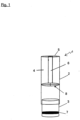
- the cartridge 1 consists of an upper circular cylindrical chamber 2 and a lower, also circular cylindrical chamber 3, which has a smaller diameter than the upper chamber 2.
- the lower chamber 3 is inserted with its upper end section into the upper chamber 2, which is open at the bottom, and is attached to the upper chamber 2 in a suitable manner, for example glued into it.
- the upper chamber 2 consists of the cylindrical peripheral wall 4, an upper annular cover wall 5 and a circular cylindrical tube 6, which extends from the edge of the central opening of the annular cover wall into the upper chamber and which has a diameter such that a suction nozzle (not shown) of a bottle pump attached to the container can be tightly inserted.
- a piston 7 is arranged in a press fit, which seals the lower chamber 3 and thus the cartridge 1 against the ingress of a liquid medium with which the container (not shown) is filled and in which the cartridge is immersed.
- the active ingredient is filled into the upper chamber 2, after which the piston 7 is inserted into the lower chamber 3.
- the suction nozzle or pump stem of a bottle pump is attached to the filled cartridge, after which the cartridge is inserted into an airless bottle filled with liquid medium and the bottle pump is attached to the neck of the bottle.
- the cartridge system is ready to dispense an aqueous solution, the two components of which are separated from each other so that the active ingredient has a long shelf life.
- the user of the cartridge system operates the pump so that a negative pressure is generated in the cartridge, which causes the piston 7 in the lower chamber 3 to rise, whereby the level of the liquid medium in the lower chamber 3 also rises.
- the piston 7 has reached the upper end of the lower chamber 3, it is drawn into the upper chamber. Since the piston 7 has a smaller diameter than the upper chamber 2, the liquid medium in the bottle now also penetrates into the upper chamber, so that the active ingredient in the upper chamber can mix with the liquid medium. Shaking the bottle achieves a quick and largely homogeneous mixture.
- the piston 7 drawn into the upper chamber floats in the upper chamber, whereby the piston collecting grid 8 prevents the piston 7 from being sucked onto the tube 6 and blocking it.
- the active ingredient mixed in the liquid medium can now be removed or applied by the consumer by further pumping the bottle.
- FIG. 3 schematically shows, the pump stem 9 of a pump 10 tightly engages the upper chamber 12 of a cartridge 13, which contains an active substance.
- the piston 15 is sucked into the chamber 12, whereby the cartridge 13 is opened and the active substance can be mixed with the liquid medium in the bottle 16.
- two tubular chambers 18 open to the outside are inserted into the peripheral wall of the cartridge 1, in each of which a piston 17 is press-fitted, the two pistons 17 being sucked into the interior of the cartridge by negative pressure in order to open the cartridge, so that the liquid medium can enter the cartridge.
- the two pistons are arranged diametrically opposite each other.
Landscapes
- Engineering & Computer Science (AREA)
- Mechanical Engineering (AREA)
- Ceramic Engineering (AREA)
- Containers And Packaging Bodies Having A Special Means To Remove Contents (AREA)
- Package Specialized In Special Use (AREA)
Abstract
Description
- Die Erfindung betrifft ein Kartuschensystem zur Abgabe einer wässrigen Lösung, die aus einer Mischung eines Wirkstoffs mit einem flüssigen Medium besteht, mit einem flaschenförmigen Behälter, auf dessen Hals eine Pumpe befestigt ist, deren Ansaugstutzen in den Behälter ragt.
- Es gibt viele Stoffe und pharmazeutische Mittel, die in einer wässrigen Lösung nicht lange haltbar sind. Hierzu gehören z.B. Vitamin C, Benzoylperoxid, Steroide für aerosole Anwendungen bei Lungenerkrankungen usw., wobei diese Aufzählung nur beispielhaft ist. Aus diesem Grund ist es vorteilhaft, solche Wirkstoffe oder Mittel und das zugehörige flüssige Medium vor der Anwendung der wässrigen Lösung möglichst lange getrennt zu halten.
- Der vorliegenden Erfindung liegt die Aufgabe zugrunde, ein System anzugeben, mit dem der Anwender den zu verabreichenden Wirkstoff erst unmittelbar vor der Anwendung mit der zugehörigen wässrigen Lösung durchmischen kann, wobei das System für jedermann leicht handhabbar sein soll.
- Diese Aufgabe wird erfindungsgemäß durch die Merkmale des Patentanspruchs 1 gelöst.
- Vorteilhafte Ausgestaltungen der Erfindung sind in den Unteransprüchen gekennzeichnet.
- Die Erfindung sieht vor, dass der Behälter mit dem flüssigen Medium füllbar ist, dass in dem Behälter eine Kartusche angeordnet ist, in deren Oberseite der Ansaugstutzen der Pumpe dicht eingesteckt ist, dass in die Kartusche der Wirkstoff einfüllbar ist, dass die Kartusche zur Außenseite hin von wenigstens einem Kolben oder Stopfen abgedichtet ist, der verschieblich in einer Wand der Kartusche angeordnet ist und durch von der Pumpe erzeugten Unterdruck ins Innere der Kartusche eintritt und diese nach außen öffnet, so dass der Wirkstoff mit dem flüssigen Medium mischbar ist. Um eine möglichst vollständige Mischung des Wirkstoffs mit dem flüssigen Medium zu erreichen, wird der Behälter von dem Anwender geschüttelt, so dass sich in dem Behälter und der Kartusche eine im wesentlichen homogene wässrige Lösung bildet, die der Benutzer durch weitere Betätigung der Pumpe abgeben kann. Dieses System ist sehr einfach zu betätigen.
- Mit Vorteil wird vorgeschlagen, dass der wenigstens eine Kolben in einer rohrförmigen, nach außen offenen Kammer sitzt, die in die Bodenwand oder Umfangswand der Kartusche eingesetzt oder einstückig mit dieser ausgebildet ist. Dabei können zwei oder auch mehr rohrförmige Kammern in die Kartuschenwand eingelassen sein, die von Kolben abgedichtet sind, die verschieblich in den rohrförmigen Kammern sitzen.
- In einer bevorzugten Ausführungform der Erfindung ist vorgesehen, dass die Kartusche eine obere Kammer, in die der Wirkstoff einfüllbar ist, und eine anschließende untere Kammer kleinerer Querschnittsabmessungen aufweist, deren offene Unterseite durch einen darin angeordneten Kolben abgedichtet ist, der durch Unterdruck in der Kartusche verschieblich in der unteren Kammer sitzt und bei Eintritt in die obere Kammer die Kartusche nach außen bzw. unten zum flüssigen Medium hin öffnet, so dass der Wirkstoff mit dem flüssigen Medium mischbar ist.
- In weiteren Einzelheiten wird vorgeschlagen, dass die obere Kammer eine zylindrische Umfangswand, vorzugsweise eine kreiszylindrische Umfangswand, aufweist, in die der Saugstutzen der auf dem Behälter befestigten Pumpe dicht einsteckbar ist. In einer Ausführungsform hat die obere Kammer eine oben anschließende ringförmigen Wand und eine mittig anschließende, nach innen ragende kreiszylindrische Innenwand kleineren Durchmessers, in die der Saugstutzen dicht eingesteckt wird. Die untere Kammer sollte aus einem zylindrischen, vorzugsweise kreiszylindrischen Rohr bestehen, das in die Umfangswand der oberen Kammer dicht eingesteckt und an dieser befestigt, vorzugsweise eingeklebt ist. Die beiden Kammern sind bevorzugt im Spritzgussverfahren hergestellt, entweder in getrennter Form oder einstückig.
- Weiter wird vorgeschlagen, dass der Kolben in einer Presspassung in der unteren Kammer sitzt, und zwar so, dass der Kolben die Kammer abdichtet, jedoch durch Unterdruck in der Kartusche verschieblich ist.
- Durch Betätigung der Pumpe gleitet der Kolben in der unteren Kammer nach oben und tritt dann in die obere Kammer größeren Durchmessers ein, wodurch eine Öffnung, vorzugsweise ein Ringspalt entsteht, durch den der Wirkstoff aus der Kartusche ins Innere des Behälters austreten, und durch den flüssiges Medium in die obere Kammer eintreten kann. Damit kann der Wirkstoff mit dem flüssigen Medium wirkungsvoll gemischt werden, bevor das Gemisch durch erneute Betätigung der Pumpe abgegeben wird.
- Damit der in der Kartusche nach oben gewanderte Kolben den Ansaugstutzen der Pumpe nicht verschließen kann, ist zweckmäßigerweise unterhalb des darin angeordneten Saugstutzens ein Anschlag für den Kolben angeordnet. Hierzu kann ein Gitterelement in die obere Kammer eingesetzt sein, das von einem Vorsprung der Kammerwand fixiert ist.
- Der Wirkstoff kann eine Pulverform haben oder in flüssiger Konsistenz in die Kartusche eingefüllt sein.
- Damit der Benutzer erfährt, wann er den Behälter schütteln soll, um die angestrebte wässrige Lösung abgeben zu können, wird mit großem Vorteil vorgeschlagen, dass der Behälter und die Kartusche aus einem durchsichtigen Kunststoff bestehen.
- Nach einem weiteren sehr vorteilhaften Vorschlag der Erfindung kann der Behälter aus einem steifen Außenbehälter und einem verformbaren Innenbeutel bestehen, in den keine Außenluft zum Druckausgleich nach Abgabe von Behälterinhalt eintritt, sondern stattdessen in den Zwischenraum zwischen dem Außenbehälter und dem Innenbeutel. Bei dieser Ausgestaltung der Erfindung ist der Innenbeutel mit dem flüssigen Medium befüllt, in dem sich auch die Kartusche befindet. Dabei werden auch weitere Umwelteinflüsse wie Luftfeuchtigkeit, Sauerstoff, UV-Licht, Mikroorganismen minimiert, wodurch die abzugebende wässrige Lösung noch länger haltbar ist.
- Weitere Einzelheiten der Erfindung ergeben sich aus der nachfolgenden Beschreibung sowie anhand der Zeichnungen. Dabei zeigen:
- Figur 1
- eine schematische Darstellung einer Ausführungsform einer erfindungsgemäßen Kartusche;
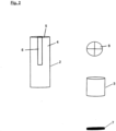
- Figur 2
- die vier Bestandteile der Kartusche gemäß
Figur 1 ; - Figur 3
- eine weitgehend schematische Darstellung einer Ausführungsform des erfindungsgemäßen Kartuschensystems;
- Figur 4
- eine schematische Darstellung einer weiteren Ausführungsform der Erfindung.
- Die Kartusche 1 besteht aus einer oberen kreiszylindrischen Kammer 2 und einer unteren ebenfalls kreiszylindrischen Kammer 3, die einen kleineren Durchmesser hat als die obere Kammer 2. Die untere Kammer 3 ist mit ihrem oberen Endabschnitt in die unten offene obere Kammer 2 eingesteckt und an der oberen Kammer 2 auf geeignete Weise befestigt, beispielsweise in diese eingeklebt. Die obere Kammer 2 besteht aus der zylindrischen Umfangswand 4, einer oberen ringförmigen Deckelwand 5 und einem kreiszylindrischen Röhrchen 6, das sich vom Rand der mittigen Öffnung der ringförmigen Deckelwand in die obere Kammer erstreckt und das einen solchen Durchmesser hat, dass ein nicht dargestellter Ansaugstutzen einer auf dem Behälter angebrachten Flaschenpumpe dicht einsteckbar ist.
- In der unteren Kammer der Kartusche 1 ist ein Kolben 7 in einer Presspassung angeordnet, der die untere Kammer 3 und damit die Kartusche 1 gegen den Eintritt eines flüssigen Mediums abdichtet, mit dem der (nicht dargestellte) Behälter gefüllt und in den die Kartusche eingetaucht ist.
- Unterhalb des Röhrchens 6 bzw. des Ansaugstutzens der Pumpe befindet sich in der oberen Kammer 2 ein Kolbenauffang-Gitter 8, das verhindert, dass das Röhrchen 6 von dem Kolben 7 verschlossen wird, wenn der Kolben 7 durch von der Pumpe erzeugten Unterdruck in die obere Kammer 2 eingesaugt wird.
- In die obere Kammer 2 wird der Wirkstoff eingefüllt, woraufhin der Kolben 7 in die untere Kammer 3 eingesetzt wird. An die so befüllte Kartusche wird der Ansaugstutzen bzw. der Pumpenstamm einer Flaschenpumpe angesteckt, woraufhin die Kartusche in eine mit flüssigem Medium gefüllte Airless-Flasche eingesetzt und die Flaschenpumpe auf dem Flaschenhals befestigt wird. In diesem Zustand ist das Kartuschensystem bereit zur Abgabe einer wässrigen Lösung, deren beide Bestandteile aber voneinander getrennt sind, so dass der Wirkstoff lange haltbar ist.
- Um die wässrige Lösung verabreichen zu können, betätigt der Benutzer des Kartuschensystems die Pumpe, so dass in der Kartusche ein Unterdruck erzeugt wird, der den Kolben 7 in der unteren Kammer 3 ansteigen lässt, wobei auch der Pegel des flüssigen Mediums in der unteren Kammer 3 ansteigt. Wenn der Kolben 7 am oberen Ende der unteren Kammer 3 angekommen ist, wird er in die obere Kammer eingezogen. Da der Kolben 7 einen kleineren Durchmesser hat als die obere Kammer 2, dringt nun auch das in der Flasche befindliche flüssige Medium in die obere Kammer ein, so dass der in der oberen Kammer befindliche Wirkstoff sich mit dem flüssigen Medium vermischen kann. Durch Schütteln der Flasche wird eine schnelle und weitgehend homogene Mischung erreicht. Der in die obere Kammer eingezogene Kolben 7 schwimmt in der oberen Kammer, wobei das Kolbenauffanggitter 8 verhindert, dass der Kolben 7 an das Röhrchen 6 angesaugt wird und dieses versperrt. Der im flüssigen Medium gemischte Wirkstoff kann nun durch weiteres Anpumpen der Flasche durch den Verbraucher entnommen bzw. appliziert werden.
- Anstelle des Kolbenauffang-Gitters 8 kann ein Versperren des Röhrchens 6 durch eine geeignete Gestaltung der Oberseite des Kolbens ausgeschlossen werden.
- Wie
Figur 3 schematisch zeigt, greift der Pumpenstamm 9 einer Pumpe 10 dicht in die einen Wirkstoff aufnehmende obere Kammer 12 einer Kartusche 13 ein. An die obere Kammer 12 ist am unteren Ende eine untere Kammer 14 kleineren Durchmessers befestigt, in der ein Kolben 15 dicht angeordnet ist. Wenn durch die Pumpe 10 ein Unterdruck in der Kammer 12 erzeugt wird, wird der Kolben 15 in die Kammer 12 hinein gesaugt, wodurch die Kartusche 13 geöffnet wird und der Wirkstoff mit dem flüssigen Medium in der Flasche 16 gemischt werden kann. - Bei der Ausführungsform der
Figur 4 sind in die Umfangswand der Kartusche 1 zwei rohrförmige, nach außen offene Kammern 18 eingesetzt, in denen jeweils ein Kolben 17 im Press-Sitz sitzt, wobei die beiden Kolben 17 durch Unterdruck in der Kartusche in deren Innenraum gesaugt wird, um die Kartusche zu öffnen, so dass das flüssige Medium in die Kartusche eintreten kann. Die beiden Kolben sind einander diametral gegenüberliegend angeordnet.
Claims (12)
- Kartuschensystem zur Abgabe einer wässrigen Lösung, die aus einer Mischung eines Wirkstoffs mit einem flüssigen Medium besteht,mit einem flaschenförmigen Behälter (16), auf dessen Hals eine Pumpe (10) befestigt ist,dadurch gekennzeichnet,dass der Behälter (16) mit dem flüssigen Medium füllbar ist,dass in dem Behälter (16) eine Kartusche (1, 13) angeordnet ist, in deren Oberseite der Ansaugstutzen (9) der Pumpe (10) dicht eingesteckt ist, dass in die Kartusche (1, 13) der Wirkstoff einfüllbar ist,dass die Kartusche (1, 13) zur Außenseite hin von wenigstens einem Kolben oder Stopfen (7, 15, 17) abgedichtet ist, der verschieblich in einer Wand der Kartusche (1, 13) angeordnet ist und durch von der Pumpe (10) erzeugten Unterdruck ins Innere der Kartusche eintritt und diese nach außen öffnet, so dass der Wirkstoff mit dem flüssigen Medium mischbar ist.
- Kartuschensystem nach Anspruch 1,
dadurch gekennzeichnet,
dass der wenigstens eine Kolben (7, 15, 17) in einer rohrförmigen, nach außen offenen Kammer (3, 14) sitzt, die in die Bodenwand oder Umfangswand der Kartusche (1, 13) eingesetzt oder einstückig mit dieser ausgebildet ist. - Kartuschensystem nach einem der Ansprüche 1 oder 2,
dadurch gekennzeichnet,
dass zwei oder mehr rohrförmige Kammern (18) in die Kartuschenwand eingelassen sind. - Kartuschensystem nach einem der Ansprüche 1 bis 3,
dadurch gekennzeichnet,
dass die Kartusche eine obere Kammer (2, 12), in die der Wirkstoff einfüllbar ist, und eine anschließende untere Kammer (3, 14) kleineren Durchmessers aufweist, die zur Außenseite der Kartusche (1, 13) von einem zugehörigen Kolben (7, 15) abgedichtet ist, und durch Unterdruck in die obere Kammer (2, 12) eintritt, und damit die Kartusche (1, 13) nach außen öffnet. - Kartuschensystem nach einem der Ansprüche 1 bis 4,
dadurch gekennzeichnet,
dass die obere Kammer (2) aus einer vorzugsweise kreiszylindrischen Umfangswand (4), einer ringförmigen oberen Wand (5) und einem mittig anschließenden kreiszylindrischen Röhrchen (6) kleineren Durchmessers besteht, das ins Innere der oberen Kammer (2) ragt und in das der Saugstutzen der Pumpe dicht einsteckbar ist. - Kartuschensystem nach einem der Ansprüche 1 bis 5,
dadurch gekennzeichnet,
dass die untere Kammer (3) aus einem zylindrischen Rohr besteht, das in die Umfangswand (4) der oberen Kammer (2) dicht eingesteckt ist oder einstückig mit der oberen Kammer ausgebildet ist. - Kartuschensystem nach einem der Ansprüche 1 bis 6,
dadurch gekennzeichnet,
dass der wenigstens eine Kolben (7) in einer Presspassung in dem zylindrischen Rohr sitzt. - Kartuschensystm nach einem der Ansprüche 1 bis 7,
dadurch gekennzeichnet,
dass in der oberen Kammer (2) unterhalb des Ansaugstutzens der Pumpe ein Anschlag für den wenigstens einen Kolben (7) angeordnet ist. - Kartuschensystem nach Anspruch 8,
dadurch gekennzeichnet,
dass als Anschlag ein Gitterelement (8) angeordnet ist. - Kartuschensystem nach einem der Ansprüche 1 bis 9,
dadurch gekennzeichnet,
dass der Behälter und die Kartusche (1) aus einem durchsichtigen Kunststoff bestehen. - Kartuschensystem nach einem der Ansprüche 1 bis 10,
dadurch gekennzeichnet,
dass der Wirkstoff eine Pulverform hat oder flüssig ist. - Kartuschensystem nach einem der Ansprüche 1 bis 11,
dadurch gekennzeichnet,
dass der Behälter (16) aus einem steifen Außenbehälter und einem verformbaren Innenbeutel besteht, in den keine Außenluft zum Druckausgleich bei Abgabe von Behälterinhalt eintritt.
Applications Claiming Priority (1)
| Application Number | Priority Date | Filing Date | Title |
|---|---|---|---|
| DE102023102632.1A DE102023102632B4 (de) | 2023-02-02 | 2023-02-02 | Kartuschensystem zur Abgabe einer wässrigen Lösung |
Publications (2)
| Publication Number | Publication Date |
|---|---|
| EP4410438A1 true EP4410438A1 (de) | 2024-08-07 |
| EP4410438B1 EP4410438B1 (de) | 2025-05-14 |
Family
ID=89430361
Family Applications (1)
| Application Number | Title | Priority Date | Filing Date |
|---|---|---|---|
| EP23219409.2A Active EP4410438B1 (de) | 2023-02-02 | 2023-12-21 | Kartuschensystem zur abgabe einer wässrigen lösung |
Country Status (5)
| Country | Link |
|---|---|
| US (1) | US12459726B2 (de) |
| EP (1) | EP4410438B1 (de) |
| CA (1) | CA3224590A1 (de) |
| DE (1) | DE102023102632B4 (de) |
| MX (1) | MX2024001619A (de) |
Citations (3)
| Publication number | Priority date | Publication date | Assignee | Title |
|---|---|---|---|---|
| US20130153602A1 (en) * | 2011-12-16 | 2013-06-20 | Ecolab Usa Inc. | Solid concentrate dispensing system |
| US20130228482A1 (en) * | 2010-11-22 | 2013-09-05 | Yonwoo Co., Ltd. | Mixing container for different contents |
| US20210268213A1 (en) * | 2018-06-15 | 2021-09-02 | Boehringer Ingelheim International Gmbh | System, cartridge and process |
Family Cites Families (6)
| Publication number | Priority date | Publication date | Assignee | Title |
|---|---|---|---|---|
| US4152378A (en) * | 1977-03-14 | 1979-05-01 | Baxter Travenol Laboratories, Inc. | Container closure having automatic opening means |
| DE19742559C2 (de) | 1997-09-26 | 1999-08-05 | Gaplast Gmbh | Behälter mit Pumpe |
| JP4400705B2 (ja) * | 2002-03-29 | 2010-01-20 | 株式会社タニ | 内容物の混合構造を有する包装容器 |
| CA2875791A1 (en) | 2012-06-06 | 2013-12-12 | Minitube Of America, Inc. | Multi-compartment container for biological liquids |
| EP2957347B1 (de) | 2014-06-18 | 2017-02-22 | Albea Thomaston Inc. | System zur abgabe einer mischung aus einem ersten und einem zweiten produkt |
| EP3484628B1 (de) * | 2016-07-18 | 2020-08-26 | RPC Bramlage GmbH | Spender für flüssige bis pastöse massen |
-
2023
- 2023-02-02 DE DE102023102632.1A patent/DE102023102632B4/de active Active
- 2023-12-21 EP EP23219409.2A patent/EP4410438B1/de active Active
- 2023-12-22 CA CA3224590A patent/CA3224590A1/en active Pending
- 2023-12-27 US US18/397,051 patent/US12459726B2/en active Active
-
2024
- 2024-02-01 MX MX2024001619A patent/MX2024001619A/es unknown
Patent Citations (3)
| Publication number | Priority date | Publication date | Assignee | Title |
|---|---|---|---|---|
| US20130228482A1 (en) * | 2010-11-22 | 2013-09-05 | Yonwoo Co., Ltd. | Mixing container for different contents |
| US20130153602A1 (en) * | 2011-12-16 | 2013-06-20 | Ecolab Usa Inc. | Solid concentrate dispensing system |
| US20210268213A1 (en) * | 2018-06-15 | 2021-09-02 | Boehringer Ingelheim International Gmbh | System, cartridge and process |
Also Published As
| Publication number | Publication date |
|---|---|
| CA3224590A1 (en) | 2025-04-10 |
| US12459726B2 (en) | 2025-11-04 |
| DE102023102632A1 (de) | 2024-08-08 |
| US20240262603A1 (en) | 2024-08-08 |
| EP4410438B1 (de) | 2025-05-14 |
| DE102023102632B4 (de) | 2026-04-30 |
| MX2024001619A (es) | 2024-08-05 |
Similar Documents
| Publication | Publication Date | Title |
|---|---|---|
| EP2605857B1 (de) | Abgabemodul | |
| DE2227407C3 (de) | Handpumpe zur Förderung von Füllgut aus einem Behälter | |
| EP2200752B1 (de) | Dosierungsvorrichtung | |
| EP0738543B1 (de) | Abgabepumpe aus Kunststoff für pastenartige Stoffe | |
| DE4206524C2 (de) | Dosierpumpe für zähflüssige, insbesondere pastenartige Stoffe | |
| DE60033929T2 (de) | Auf einer platte befestigter spender für eine viskose flüssigkeit mit verbessertem behälter | |
| EP2605858B1 (de) | Abgabemodul und verfahren zum befüllen eines abgabemoduls | |
| EP1327478B1 (de) | Betätigungskopf einer Saug-Druck-Pumpe zum Ausspritzen eines Produkts aus einem Behältnis | |
| DE2744392A1 (de) | Vorrichtung zur abgabe eines fliessfaehigen stoffes zum zeitpunkt des gebrauchs | |
| DE1653419A1 (de) | Fluessigkeitsabgabepumpe | |
| DE69816336T2 (de) | Aufbewahrungs- und ausgabevorrichtung für ein produkt, mit einer handbetätigten pumpe und lufteinlassfilter | |
| DE10300494A1 (de) | Pumpe zum Abgeben von fließfähigem Material | |
| EP0473965A1 (de) | Austragvorrichtung für Medien | |
| DE2818507A1 (de) | Handbetaetigte axialkolbenpumpe | |
| DE3425900C2 (de) | Vorrichtung mit Tropfenzähler zum Abgeben einer flüssigen oder pastösen Substanz | |
| EP1038796A2 (de) | Behälter zur Aufbewahrung von pastösen oder fluiden Massen und deren dosierter Abgabe | |
| DE2324296A1 (de) | Mischbehaelter fuer dentalpraeparate | |
| DE2640837A1 (de) | Manuell betaetigbare pumpe | |
| DE69626184T2 (de) | Herstellungsverfahren für eine abgabeflasche mit einem flexiblen beutel | |
| DE1027945B (de) | Abgabeventil | |
| DE69209788T2 (de) | Pumpe zur Förderung von einem flüssigen oder pastösen Produkt, und Ausgabebehälter mit einer solchen Pumpe | |
| EP3736049A1 (de) | Austragkopf und flüssigkeitsspender mit einem austragkopf | |
| EP4410438B1 (de) | Kartuschensystem zur abgabe einer wässrigen lösung | |
| CH641248A5 (en) | Manually actuated piston pump for delivering contents from a container, e.g. packaging container, into the open air | |
| WO2010133209A1 (de) | Misch- und abgabevorrichtung |
Legal Events
| Date | Code | Title | Description |
|---|---|---|---|
| PUAI | Public reference made under article 153(3) epc to a published international application that has entered the european phase |
Free format text: ORIGINAL CODE: 0009012 |
|
| STAA | Information on the status of an ep patent application or granted ep patent |
Free format text: STATUS: THE APPLICATION HAS BEEN PUBLISHED |
|
| AK | Designated contracting states |
Kind code of ref document: A1 Designated state(s): AL AT BE BG CH CY CZ DE DK EE ES FI FR GB GR HR HU IE IS IT LI LT LU LV MC ME MK MT NL NO PL PT RO RS SE SI SK SM TR |
|
| STAA | Information on the status of an ep patent application or granted ep patent |
Free format text: STATUS: REQUEST FOR EXAMINATION WAS MADE |
|
| 17P | Request for examination filed |
Effective date: 20241002 |
|
| RBV | Designated contracting states (corrected) |
Designated state(s): AL AT BE BG CH CY CZ DE DK EE ES FI FR GB GR HR HU IE IS IT LI LT LU LV MC ME MK MT NL NO PL PT RO RS SE SI SK SM TR |
|
| GRAP | Despatch of communication of intention to grant a patent |
Free format text: ORIGINAL CODE: EPIDOSNIGR1 |
|
| STAA | Information on the status of an ep patent application or granted ep patent |
Free format text: STATUS: GRANT OF PATENT IS INTENDED |
|
| RIC1 | Information provided on ipc code assigned before grant |
Ipc: B05B 15/30 20180101ALI20250124BHEP Ipc: B05B 11/00 20230101AFI20250124BHEP |
|
| GRAS | Grant fee paid |
Free format text: ORIGINAL CODE: EPIDOSNIGR3 |
|
| INTG | Intention to grant announced |
Effective date: 20250305 |
|
| GRAA | (expected) grant |
Free format text: ORIGINAL CODE: 0009210 |
|
| STAA | Information on the status of an ep patent application or granted ep patent |
Free format text: STATUS: THE PATENT HAS BEEN GRANTED |
|
| AK | Designated contracting states |
Kind code of ref document: B1 Designated state(s): AL AT BE BG CH CY CZ DE DK EE ES FI FR GB GR HR HU IE IS IT LI LT LU LV MC ME MK MT NL NO PL PT RO RS SE SI SK SM TR |
|
| P01 | Opt-out of the competence of the unified patent court (upc) registered |
Free format text: CASE NUMBER: APP_16241/2025 Effective date: 20250403 |
|
| REG | Reference to a national code |
Ref country code: GB Ref legal event code: FG4D Free format text: NOT ENGLISH |
|
| REG | Reference to a national code |
Ref country code: CH Ref legal event code: EP |
|
| REG | Reference to a national code |
Ref country code: IE Ref legal event code: FG4D Free format text: LANGUAGE OF EP DOCUMENT: GERMAN |
|
| REG | Reference to a national code |
Ref country code: DE Ref legal event code: R096 Ref document number: 502023000997 Country of ref document: DE |
|
| REG | Reference to a national code |
Ref country code: NL Ref legal event code: MP Effective date: 20250514 |
|
| PG25 | Lapsed in a contracting state [announced via postgrant information from national office to epo] |
Ref country code: ES Free format text: LAPSE BECAUSE OF FAILURE TO SUBMIT A TRANSLATION OF THE DESCRIPTION OR TO PAY THE FEE WITHIN THE PRESCRIBED TIME-LIMIT Effective date: 20250514 Ref country code: PT Free format text: LAPSE BECAUSE OF FAILURE TO SUBMIT A TRANSLATION OF THE DESCRIPTION OR TO PAY THE FEE WITHIN THE PRESCRIBED TIME-LIMIT Effective date: 20250915 Ref country code: FI Free format text: LAPSE BECAUSE OF FAILURE TO SUBMIT A TRANSLATION OF THE DESCRIPTION OR TO PAY THE FEE WITHIN THE PRESCRIBED TIME-LIMIT Effective date: 20250514 |
|
| REG | Reference to a national code |
Ref country code: LT Ref legal event code: MG9D |
|
| PG25 | Lapsed in a contracting state [announced via postgrant information from national office to epo] |
Ref country code: NO Free format text: LAPSE BECAUSE OF FAILURE TO SUBMIT A TRANSLATION OF THE DESCRIPTION OR TO PAY THE FEE WITHIN THE PRESCRIBED TIME-LIMIT Effective date: 20250814 Ref country code: GR Free format text: LAPSE BECAUSE OF FAILURE TO SUBMIT A TRANSLATION OF THE DESCRIPTION OR TO PAY THE FEE WITHIN THE PRESCRIBED TIME-LIMIT Effective date: 20250815 |
|
| PG25 | Lapsed in a contracting state [announced via postgrant information from national office to epo] |
Ref country code: NL Free format text: LAPSE BECAUSE OF FAILURE TO SUBMIT A TRANSLATION OF THE DESCRIPTION OR TO PAY THE FEE WITHIN THE PRESCRIBED TIME-LIMIT Effective date: 20250514 Ref country code: PL Free format text: LAPSE BECAUSE OF FAILURE TO SUBMIT A TRANSLATION OF THE DESCRIPTION OR TO PAY THE FEE WITHIN THE PRESCRIBED TIME-LIMIT Effective date: 20250514 |
|
| PG25 | Lapsed in a contracting state [announced via postgrant information from national office to epo] |
Ref country code: BG Free format text: LAPSE BECAUSE OF FAILURE TO SUBMIT A TRANSLATION OF THE DESCRIPTION OR TO PAY THE FEE WITHIN THE PRESCRIBED TIME-LIMIT Effective date: 20250514 |
|
| PG25 | Lapsed in a contracting state [announced via postgrant information from national office to epo] |
Ref country code: HR Free format text: LAPSE BECAUSE OF FAILURE TO SUBMIT A TRANSLATION OF THE DESCRIPTION OR TO PAY THE FEE WITHIN THE PRESCRIBED TIME-LIMIT Effective date: 20250514 |
|
| PG25 | Lapsed in a contracting state [announced via postgrant information from national office to epo] |
Ref country code: RS Free format text: LAPSE BECAUSE OF FAILURE TO SUBMIT A TRANSLATION OF THE DESCRIPTION OR TO PAY THE FEE WITHIN THE PRESCRIBED TIME-LIMIT Effective date: 20250814 |
|
| PG25 | Lapsed in a contracting state [announced via postgrant information from national office to epo] |
Ref country code: IS Free format text: LAPSE BECAUSE OF FAILURE TO SUBMIT A TRANSLATION OF THE DESCRIPTION OR TO PAY THE FEE WITHIN THE PRESCRIBED TIME-LIMIT Effective date: 20250914 |
|
| PG25 | Lapsed in a contracting state [announced via postgrant information from national office to epo] |
Ref country code: LV Free format text: LAPSE BECAUSE OF FAILURE TO SUBMIT A TRANSLATION OF THE DESCRIPTION OR TO PAY THE FEE WITHIN THE PRESCRIBED TIME-LIMIT Effective date: 20250514 |
|
| PG25 | Lapsed in a contracting state [announced via postgrant information from national office to epo] |
Ref country code: DK Free format text: LAPSE BECAUSE OF FAILURE TO SUBMIT A TRANSLATION OF THE DESCRIPTION OR TO PAY THE FEE WITHIN THE PRESCRIBED TIME-LIMIT Effective date: 20250514 Ref country code: SM Free format text: LAPSE BECAUSE OF FAILURE TO SUBMIT A TRANSLATION OF THE DESCRIPTION OR TO PAY THE FEE WITHIN THE PRESCRIBED TIME-LIMIT Effective date: 20250514 |
|
| PGFP | Annual fee paid to national office [announced via postgrant information from national office to epo] |
Ref country code: AT Payment date: 20260113 Year of fee payment: 3 |
|
| PGFP | Annual fee paid to national office [announced via postgrant information from national office to epo] |
Ref country code: FR Payment date: 20251231 Year of fee payment: 3 |
|
| PGFP | Annual fee paid to national office [announced via postgrant information from national office to epo] |
Ref country code: TR Payment date: 20251114 Year of fee payment: 3 |
|
| PG25 | Lapsed in a contracting state [announced via postgrant information from national office to epo] |
Ref country code: CZ Free format text: LAPSE BECAUSE OF FAILURE TO SUBMIT A TRANSLATION OF THE DESCRIPTION OR TO PAY THE FEE WITHIN THE PRESCRIBED TIME-LIMIT Effective date: 20250514 |
|
| PG25 | Lapsed in a contracting state [announced via postgrant information from national office to epo] |
Ref country code: EE Free format text: LAPSE BECAUSE OF FAILURE TO SUBMIT A TRANSLATION OF THE DESCRIPTION OR TO PAY THE FEE WITHIN THE PRESCRIBED TIME-LIMIT Effective date: 20250514 |
|
| PG25 | Lapsed in a contracting state [announced via postgrant information from national office to epo] |
Ref country code: SK Free format text: LAPSE BECAUSE OF FAILURE TO SUBMIT A TRANSLATION OF THE DESCRIPTION OR TO PAY THE FEE WITHIN THE PRESCRIBED TIME-LIMIT Effective date: 20250514 |
|
| REG | Reference to a national code |
Ref country code: DE Ref legal event code: R097 Ref document number: 502023000997 Country of ref document: DE |
|
| PG25 | Lapsed in a contracting state [announced via postgrant information from national office to epo] |
Ref country code: RO Free format text: LAPSE BECAUSE OF FAILURE TO SUBMIT A TRANSLATION OF THE DESCRIPTION OR TO PAY THE FEE WITHIN THE PRESCRIBED TIME-LIMIT Effective date: 20250514 |
|
| PLBE | No opposition filed within time limit |
Free format text: ORIGINAL CODE: 0009261 |
|
| STAA | Information on the status of an ep patent application or granted ep patent |
Free format text: STATUS: NO OPPOSITION FILED WITHIN TIME LIMIT |
|
| REG | Reference to a national code |
Ref country code: CH Ref legal event code: L10 Free format text: ST27 STATUS EVENT CODE: U-0-0-L10-L00 (AS PROVIDED BY THE NATIONAL OFFICE) Effective date: 20260325 |
|
| PGFP | Annual fee paid to national office [announced via postgrant information from national office to epo] |
Ref country code: DE Payment date: 20260216 Year of fee payment: 3 |
|
| PGFP | Annual fee paid to national office [announced via postgrant information from national office to epo] |
Ref country code: IT Payment date: 20251231 Year of fee payment: 3 |
|
| 26N | No opposition filed |
Effective date: 20260217 |