EP4407916A2 - Benutzergerät und verfahren zur übertragung eines synchronisationssignalblocks davon - Google Patents
Benutzergerät und verfahren zur übertragung eines synchronisationssignalblocks davon Download PDFInfo
- Publication number
- EP4407916A2 EP4407916A2 EP24180279.2A EP24180279A EP4407916A2 EP 4407916 A2 EP4407916 A2 EP 4407916A2 EP 24180279 A EP24180279 A EP 24180279A EP 4407916 A2 EP4407916 A2 EP 4407916A2
- Authority
- EP
- European Patent Office
- Prior art keywords
- pss
- psbch
- sss
- ssb
- ofdm symbols
- Prior art date
- Legal status (The legal status is an assumption and is not a legal conclusion. Google has not performed a legal analysis and makes no representation as to the accuracy of the status listed.)
- Pending
Links
Images


Classifications
-
- H—ELECTRICITY
- H04—ELECTRIC COMMUNICATION TECHNIQUE
- H04W—WIRELESS COMMUNICATION NETWORKS
- H04W4/00—Services specially adapted for wireless communication networks; Facilities therefor
- H04W4/30—Services specially adapted for particular environments, situations or purposes
- H04W4/40—Services specially adapted for particular environments, situations or purposes for vehicles, e.g. vehicle-to-pedestrians [V2P]
-
- H—ELECTRICITY
- H04—ELECTRIC COMMUNICATION TECHNIQUE
- H04J—MULTIPLEX COMMUNICATION
- H04J11/00—Orthogonal multiplex systems, e.g. using WALSH codes
- H04J11/0069—Cell search, i.e. determining cell identity [cell-ID]
- H04J11/0073—Acquisition of primary synchronisation channel, e.g. detection of cell-ID within cell-ID group
-
- H—ELECTRICITY
- H04—ELECTRIC COMMUNICATION TECHNIQUE
- H04J—MULTIPLEX COMMUNICATION
- H04J11/00—Orthogonal multiplex systems, e.g. using WALSH codes
- H04J11/0069—Cell search, i.e. determining cell identity [cell-ID]
- H04J11/0076—Acquisition of secondary synchronisation channel, e.g. detection of cell-ID group
-
- H—ELECTRICITY
- H04—ELECTRIC COMMUNICATION TECHNIQUE
- H04L—TRANSMISSION OF DIGITAL INFORMATION, e.g. TELEGRAPHIC COMMUNICATION
- H04L27/00—Modulated-carrier systems
- H04L27/26—Systems using multi-frequency codes
- H04L27/2601—Multicarrier modulation systems
- H04L27/2602—Signal structure
-
- H—ELECTRICITY
- H04—ELECTRIC COMMUNICATION TECHNIQUE
- H04L—TRANSMISSION OF DIGITAL INFORMATION, e.g. TELEGRAPHIC COMMUNICATION
- H04L27/00—Modulated-carrier systems
- H04L27/26—Systems using multi-frequency codes
- H04L27/2601—Multicarrier modulation systems
- H04L27/2602—Signal structure
- H04L27/261—Details of reference signals
-
- H—ELECTRICITY
- H04—ELECTRIC COMMUNICATION TECHNIQUE
- H04L—TRANSMISSION OF DIGITAL INFORMATION, e.g. TELEGRAPHIC COMMUNICATION
- H04L27/00—Modulated-carrier systems
- H04L27/26—Systems using multi-frequency codes
- H04L27/2601—Multicarrier modulation systems
- H04L27/2647—Arrangements specific to the receiver only
- H04L27/2655—Synchronisation arrangements
- H04L27/2666—Acquisition of further OFDM parameters, e.g. bandwidth, subcarrier spacing, or guard interval length
-
- H—ELECTRICITY
- H04—ELECTRIC COMMUNICATION TECHNIQUE
- H04L—TRANSMISSION OF DIGITAL INFORMATION, e.g. TELEGRAPHIC COMMUNICATION
- H04L5/00—Arrangements affording multiple use of the transmission path
- H04L5/0001—Arrangements for dividing the transmission path
- H04L5/0003—Two-dimensional division
- H04L5/0005—Time-frequency
- H04L5/0007—Time-frequency the frequencies being orthogonal, e.g. OFDM(A) or DMT
-
- H—ELECTRICITY
- H04—ELECTRIC COMMUNICATION TECHNIQUE
- H04L—TRANSMISSION OF DIGITAL INFORMATION, e.g. TELEGRAPHIC COMMUNICATION
- H04L5/00—Arrangements affording multiple use of the transmission path
- H04L5/003—Arrangements for allocating sub-channels of the transmission path
- H04L5/0048—Allocation of pilot signals, i.e. of signals known to the receiver
- H04L5/0051—Allocation of pilot signals, i.e. of signals known to the receiver of dedicated pilots, i.e. pilots destined for a single user or terminal
-
- H—ELECTRICITY
- H04—ELECTRIC COMMUNICATION TECHNIQUE
- H04L—TRANSMISSION OF DIGITAL INFORMATION, e.g. TELEGRAPHIC COMMUNICATION
- H04L5/00—Arrangements affording multiple use of the transmission path
- H04L5/003—Arrangements for allocating sub-channels of the transmission path
- H04L5/0053—Allocation of signalling, i.e. of overhead other than pilot signals
-
- H—ELECTRICITY
- H04—ELECTRIC COMMUNICATION TECHNIQUE
- H04W—WIRELESS COMMUNICATION NETWORKS
- H04W48/00—Access restriction; Network selection; Access point selection
- H04W48/08—Access restriction or access information delivery, e.g. discovery data delivery
- H04W48/10—Access restriction or access information delivery, e.g. discovery data delivery using broadcasted information
-
- H—ELECTRICITY
- H04—ELECTRIC COMMUNICATION TECHNIQUE
- H04W—WIRELESS COMMUNICATION NETWORKS
- H04W56/00—Synchronisation arrangements
Definitions
- the present disclosure relates to the field of communication systems, and more particularly, to a user equipment and a method for transmitting a synchronization signal block (SSB) of the same.
- SSB synchronization signal block
- V2V direct vehicle-to-vehicle
- V2X vehicle-to-everything
- ITS intelligent transportation system
- LTE-V2X Long term evolution-V2X
- 3GPP 3rd generation partnership project
- NR new radio
- SSB synchronization signal block
- An object of the present disclosure is to propose an apparatus and a method for discontinuous reception of the same capable of performing UE-UE scheduling in vehicle-to-everything (V2X) communication and improving reliability.
- V2X vehicle-to-everything
- a user equipment for transmitting a synchronization signal block includes a memory, a transceiver, and a processor coupled to the memory and the transceiver.
- the processor is configured to control the transceiver to transmit a resource set associated with an SSB within a subframe or slot, and the SSB includes sidelink primary synchronization signal (S-PSS), sidelink secondary synchronization signal (S-SSS), and physical sidelink broadcast channel (PSBCH), and the resource set includes two orthogonal frequency division multiplexing (OFDM) symbols used for the S-PSS, two OFDM symbols used for the S-SSS, more than 1 OFDM symbol used for the PSBCH, and 0 to 1 OFDM symbol within the OFDM symbols used for the PSBCH is between the OFDM symbols for the S-PSS and the S-SSS, and positions of the OFDM symbols used for the S-PSS are in front of positions of the OFDM symbols used for the S-SSS.
- OFDM orthogonal frequency division multiplexing
- a method for transmitting a synchronization signal block (SSB) of a user equipment includes transmitting a resource set associated with an SSB within a subframe or slot, wherein the SSB includes sidelink primary synchronization signal (S-PSS), sidelink secondary synchronization signal (S-SSS), and physical sidelink broadcast channel (PSBCH), and the resource set includes two orthogonal frequency division multiplexing (OFDM) symbols used for the S-PSS, two OFDM symbols used for the S-SSS, more than 1 OFDM symbol used for the PSBCH, and 0 to 1 OFDM symbol within the OFDM symbols used for the PSBCH is between the OFDM symbols for the S-PSS and the S-SSS, and positions of the OFDM symbols used for the S-PSS are in front of positions of the OFDM symbols used for the S-SSS.
- OFDM orthogonal frequency division multiplexing
- a non-transitory machine-readable storage medium has stored thereon instructions that, when executed by a computer, cause the computer to perform the above method.
- a terminal device includes a processor and a memory configured to store a computer program.
- the processor is configured to execute the computer program stored in the memory to perform the above method.
- NR-V2X new radio vehicle-to-everything
- LTE-V2X long term evolution V2X
- SLSS sidelink synchronization signal
- PSBCH physical sidelink broadcast channel
- OFDM orthogonal frequency division multiplexing
- S-PSS sidelink primary synchronization signal
- S-SSS sidelink secondary synchronization signal
- DMRS demodulation reference signal
- rest OFDM symbols are used for the PSBCH, or an automatic gain control (AGC) symbol, or a guard period (GP) symbol.
- AGC automatic gain control
- GP guard period
- FIG. 1 illustrates that, in some embodiments, a user equipment (UE) 10 and another user equipment 20 for transmitting a synchronization signal block (SSB) according to an embodiment of the present disclosure are provided.
- the UE 10 may include a processor 11, a memory 12, and a transceiver 13.
- the UE 20 may include a processor 21, a memory 22, and a transceiver 23.
- the processor 11 or 21 may be configured to implement proposed functions, procedures and/or methods described in this description. Layers of radio interface protocol may be implemented in the processor 11 or 21.
- the memory 12 or 22 is operatively coupled with the processor 11 or 21 and stores a variety of information to operate the processor 11 or 21.
- the transceiver 13 or 23 is operatively coupled with the processor 11 or 21, and the transceiver 13 or 23 transmits and/or receives a radio signal.
- the processor 11 or 21 may include an application-specific integrated circuit (ASIC), other chipsets, logic circuit and/or data processing devices.
- the memory 12 or 22 may include a read-only memory (ROM), a random access memory (RAM), a flash memory, a memory card, a storage medium and/or other storage devices.
- the transceiver 13 or 23 may include baseband circuitry to process radio frequency signals.
- modules e.g., procedures, functions, and so on
- the modules can be stored in the memory 12 or 22 and executed by the processor 11 or 21.
- the memory 12 or 22 can be implemented within the processor 11 or 21 or external to the processor 11 or 21, in which those can be communicatively coupled to the processor 11 or 21 via various means are known in the art.
- the communication between UEs relates to vehicle-to-everything (V2X) communication including vehicle-to-vehicle (V2V), vehicle-to-pedestrian (V2P), and vehicle-to-infrastructure/network (V2I/N) according to a sidelink technology developed under 3rd generation partnership project (3GPP) release 14, 15, 16, and beyond.
- UEs communicate with each other directly via a sidelink interface such as a PC5 interface.
- FIG. 1 illustrates that, in some embodiments, the processor 11 is configured to control the transceiver 13 to transmit a resource set associated with an SSB within a subframe or slot
- the SSB includes sidelink primary synchronization signal (S-PSS), sidelink secondary synchronization signal (S-SSS), and physical sidelink broadcast channel (PSBCH)
- the resource set includes two orthogonal frequency division multiplexing (OFDM) symbols used for the S-PSS, two OFDM symbols used for the S-SSS, more than 1 OFDM symbol used for the PSBCH, and 0 to 1 OFDM symbol within the OFDM symbols used for the PSBCH is between the OFDM symbols for the S-PSS and the S-SSS.
- positions of the OFDM symbols used for the S-PSS are in front of positions of the OFDM symbols used for the S-SSS.
- the two OFDM symbols used for the S-PSS are adjacent OFDM symbols.
- the same S-PSS sequence is mapped on the two OFDM symbols.
- the two OFDM symbols used for the S-SSS are adjacent OFDM symbols.
- the same S-SSS sequence is mapped on the two OFDM symbols.
- a first OFDM symbol used for the PSBCH after the OFDM symbol used for the S-PSS includes resources used for DMRS which is configured to decode the PSBCH.
- the DMRS occupies odd or even sub-carriers or resource elements within a physical resource block (PRB).
- PRB physical resource block
- parameters configured to determine a comb-like resource mapping of the PSBCH are pre-configured or configured by a network.
- frequency resources of the S-PSS and the S-SSS are same.
- the resource set includes a resource configured to transmit the PSBCH
- the resource configured to transmit the PSBCH includes a resource configured to transmit a PSBCH payload and a resource configured to transmit a demodulation reference signal (DMRS) which is configured to decode the PSBCH.
- DMRS demodulation reference signal
- within the SSB there are a plurality of adjacent orthogonal frequency division multiplexing (OFDM) symbols used for the S-PSS, there are a plurality of adjacent OFDM symbols used for the S-SSS, there are 0 to 1 OFDM symbol used for the PSBCH, and positions of the adjacent OFDM symbols used for the S-PSS are in front of positions of the adjacent OFDM symbols used for the S-SSS.
- the SSB further includes an automatic gain control (AGC) symbol positioned in front of the S-PSS.
- AGC automatic gain control
- the AGC symbol is at beginning of the slot and mapped with the PSBCH or configured to pad bits. In some embodiments, the AGC symbol is comb-like mapped with the PSBCH. In some embodiments, the SSB further includes a guard period (GP) symbol positioned in rear of the S-SSS. In some embodiments, the GP symbol is left empty or the GP symbol is comb-like mapped with the PSBCH. In some embodiments, frequency resources of the S-PSS and the S-SSS are same. In some embodiments, the frequency resource includes frequency resource size and/or starting position. In some embodiments, frequency resource sizes of the S-PSS and the S-SSS are same.
- GP guard period
- starting positions in a frequency domain of the S-PSS and the S-PSS are same.
- the S-SSS can also be in front of the S-PSS.
- the S-PSS can also be in between of the two OFDM symbols used for S-SSS.
- the S-PSS is in front of the S-SSS or the S-SSS is in front of the S-PSS.
- parameters configured to determine a comb-like resource mapping are pre-configured or configured by a network.
- the SSB is located at a frequency center of a carrier or a frequency location of the SSB is pre-configured or configured by a network.
- a position of the SSB in a time domain is pre-configured or configured by a network.
- a periodicity of the SSB is pre-configured or configured by a network.
- a comb-like resource mapping of the S-PSS is onto a first or last OFDM symbol of the SSB.
- a comb-like resource mapping of the S-SSS is onto a first or last OFDM symbol of the SSB.
- a comb-like resource mapping of the PSBCH is onto a first or last OFDM symbol of the SSB. In some embodiments, if the S-PSS is comb-like mapped to one OFDM symbol, rest OFDM symbols used for the S-PSS are also comb-like mapped. In some embodiments, if the S-SSS is comb-like mapped to one OFDM symbol, rest OFDM symbols used for the S-SSS are also comb-like mapped.
- FIG. 2 illustrates a method 200 for transmitting a synchronization signal block (SSB) of a user equipment according to an embodiment of the present disclosure.
- the method 200 includes: a block 202, transmitting a resource set associated with an SSB within a subframe or slot, wherein the SSB includes sidelink primary synchronization signal (S-PSS), sidelink secondary synchronization signal (S-SSS), and physical sidelink broadcast channel (PSBCH), and the resource set includes two orthogonal frequency division multiplexing (OFDM) symbols used for the S-PSS, two OFDM symbols used for the S-SSS, more than 1 OFDM symbol used for the PSBCH, and 0 to 1 OFDM symbol within the OFDM symbols used for the PSBCH is between the OFDM symbols for the S-PSS and the S-SSS, and positions of the OFDM symbols used for the S-PSS are in front of positions of the OFDM symbols used for the S-SSS.
- OFDM orthogonal frequency division multiplexing
- the two OFDM symbols used for the S-PSS are adjacent OFDM symbols.
- the same S-PSS sequence is mapped on the two OFDM symbols.
- the two OFDM symbols used for the S-SSS are adjacent OFDM symbols.
- the same S-SSS sequence is mapped on the two OFDM symbols.
- a first OFDM symbol used for the PSBCH after the OFDM symbol used for the S-PSS includes resources used for DMRS which is configured to decode the PSBCH.
- the DMRS occupies odd or even sub-carriers or resource elements within a physical resource block (PRB).
- PRB physical resource block
- parameters configured to determine a comb-like resource mapping of the PSBCH are pre-configured or configured by a network.
- frequency resources of the S-PSS and the S-SSS are same.
- the resource set includes a resource configured to transmit the PSBCH
- the resource configured to transmit the PSBCH includes a resource configured to transmit a PSBCH payload and a resource configured to transmit a demodulation reference signal (DMRS) which is configured to decode the PSBCH.3.
- DMRS demodulation reference signal
- within the SSB there are a plurality of adjacent orthogonal frequency division multiplexing (OFDM) symbols used for the S-PSS, there are a plurality of adjacent OFDM symbols used for the S-SSS, there are 0 to 1 OFDM symbol used for the PSBCH, and positions of the adjacent OFDM symbols used for the S-PSS are in front of positions of the adjacent OFDM symbols used for the S-SSS.
- the SSB further includes an automatic gain control (AGC) symbol positioned in front of the S-PSS.
- AGC automatic gain control
- the AGC symbol is at beginning of the slot and mapped with the PSBCH or configured to pad bits. In some embodiments, the AGC symbol is comb-like mapped with the PSBCH. In some embodiments, the SSB further includes a guard period (GP) symbol positioned in rear of the S-SSS. In some embodiments, the GP symbol is left empty or the GP symbol is comb-like mapped with the PSBCH. In some embodiments, frequency resources of the S-PSS and the S-SSS are same. In some embodiments, the frequency resource includes frequency resource size and/or starting position. In some embodiments, frequency resource sizes of the S-PSS and the S-SSS are same.
- GP guard period
- starting positions in a frequency domain of the S-PSS and the S-PSS are same.
- the S-SSS can also be in front of the S-PSS.
- the S-PSS can also be in between of the two OFDM symbols used for S-SSS.
- the S-PSS is in front of the S-SSS or the S-SSS is in front of the S-PSS.
- parameters configured to determine a comb-like resource mapping are pre-configured or configured by a network.
- the SSB is located at a frequency center of a carrier or a frequency location of the SSB is pre-configured or configured by a network.
- a position of the SSB in a time domain is pre-configured or configured by a network.
- a periodicity of the SSB is pre-configured or configured by a network.
- a comb-like resource mapping of the S-PSS is onto a first or last OFDM symbol of the SSB.
- a comb-like resource mapping of the S-SSS is onto a first or last OFDM symbol of the SSB.
- a comb-like resource mapping of the PSBCH is onto a first or last OFDM symbol of the SSB. In some embodiments, if the S-PSS is comb-like mapped to one OFDM symbol, rest OFDM symbols used for the S-PSS are also comb-like mapped. In some embodiments, if the S-SSS is comb-like mapped to one OFDM symbol, rest OFDM symbols used for the S-SSS are also comb-like mapped.
- a resource set which is used to transmit SLSS and PSBCH can be called as an SSB.
- the SSB can be transmitted within a subframe or slot.
- the SSB includes at least S-PSS, S-SSS, and PSBCH. It can be understood that a resource that is used for transmitting PSBCH includes both a resource used for transmitting a PSBCH payload and a resource used for transmitting a DMRS which is used for decoding the PSBCH.
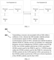
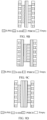
- FIGs. 3A, 3B, 3C , and 3D illustrate that, in some embodiments, within an SSB, there are two adjacent OFDM symbols used for S-PSS, two adjacent OFDM symbols used for S-SSS, more than 1 OFDM symbol used for a PSBCH.
- FIG. 3A illustrates that, in some embodiments, within an SSB, there are two adjacent OFDM symbols used for S-PSS, two adjacent OFDM symbols used for S-SSS.
- the OFDM symbols of the S-PSS are at the beginning of the SSB.
- There are two adjacent OFDM symbols used for the S-SSS and the OFDM symbols of the S-SSS are at the end of the SSB.
- the OFDM symbols of the PSBCH are between the S-PSS and the S-SSS.
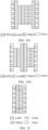
- FIG. 3B illustrates that, in some embodiments, within an SSB, there are two adjacent OFDM symbols used for S-PSS, the OFDM symbols of the S-PSS are at the beginning of the SSB. There are 2 OFDM symbols used for the PSBCH. One OFDM symbol of the PSBCH is before a position of S-SSS symbol and another OFDM symbol of the PSBCH is after a position of S-SSS symbol. For example, within the SSB, 1st and 2nd OFDM symbols used for the S-PSS, 3rd and 6th OFDM symbols used for the PSBCH, 4th and 5th OFDM symbols used for the S-SSS.
- FIG. 3C illustrates that, in some embodiments, within an SSB, OFDM symbols for S-PSS are at the beginning of the SSB.
- Two OFDM symbols of the PSBCH are before a position of S-SSS symbol and another OFDM symbol of the PSBCH is after a position of S-SSS symbol.
- FIG. 3D illustrates that, in some embodiments, within an SSB, OFDM symbols for S-PSS are at the beginning of the SSB.
- Two OFDM symbols of the PSBCH are before a position of S-SSS OFDM symbols and another two OFDM symbols of the PSBCH are after a position of S-SSS OFDM symbols.
- a frequency resource of PSBCH can be larger than the S-PSS and the S-SSS. For example, 24 resource blocks (RBs) used for the PSBCH per an OFDM symbol, and only 12 RBs used for the S-PSS or the S-SSS per an OFDM symbol. If a frequency resource of the PSBCH is larger than the S-PSS and/or the S-SSS, a part of a frequency resource on the OFDM symbols used for the S-PSS and/or the S-SSS can also be used for the PSBCH, which is illustrated in FIGs. 4A and 4B .
- the frequency resources of the PSBCH and the S-SSS can be aligned, or the frequency resources of the PSBCH and the S-PSS can be aligned.
- FIGs. 4A and 4B are an illustration of how to map the PSBCH on the OFDM symbols used for the S-PSS and/or the S-SSS of FIG. 3D .
- the mechanism can also be applied to other figures such as FIGs. 3A, 3B, and 3C .
- resources used for a PSBCH transmission includes resources used for both a PSBCH payload and a DMRS.
- the DMRS are mapped to some resource element of the resource block (RB) which is used to map the PSBCH payload.
- RB resource block
- the DMRS can occupy the even or odd resource elements per RB.
- This multiplexing scheme can be applied to a cyclic prefix orthogonal frequency division multiplexing (CP-OFDM) system.
- CP-OFDM cyclic prefix orthogonal frequency division multiplexing
- the DMRS can occupy a separate OFDM symbol which is different with the OFDM symbols used for the PSBCH payload.
- the 3rd and 7th OFDM symbols are used for the DMRS
- the 4th and 8th OFDM symbols are used for the PSBCH payload.
- This multiplexing scheme can be applied to a discrete fourier transform spread orthogonal frequency division multiplexing (DFT-s-OFDM) system.
- DFT-s-OFDM discrete fourier transform spread orthogonal frequency division multiplexing
- FIG. 3A One illustration of FIG. 3A with additional AGC and GP symbols is illustrated in FIG. 6 .
- the AGC symbol can be mapped with the PSBCH or padding bits.
- comb-like resource mapping can be applied, which is similar as the first OFDM symbol in FIG. 7A , the rest resource elements that are not mapped by the PSBCH are left empty.
- the GP symbol can be left empty.
- the GP symbol can be comb-like mapped by the PSBCH which is similar as the last OFDM symbol in FIG. 7A , the rest resource elements that are not mapped by the PSBCH are left empty.
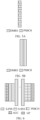
- FIGs. 7A and 7B illustrate that, in some embodiments, the OFDM symbols are used for the S-PSS and the S-SSS, comb-like resource mapping is applied to a S-PSS sequence and a S-SSS sequence separately.
- FIG. 7A illustrates that, in some embodiments, within an SSB, there are one OFDM symbol used for a S-PSS, one OFDM symbol used for a S-SSS, more than 1OFDM symbol used for a PSBCH.
- the OFDM symbol used for the S-PSS is at the beginning of the SSB.
- the OFDM symbol used for the S-SSS is at the end of the SSB.
- a S-PSS sequence is mapped to one resource element per A resource elements on the S-PSS OFDM symbol, i.e., the number of resource elements of adjacent S-PSS signal on the S-PSS OFDM symbol is A.
- a S-SSS sequence is mapped to one resource element per B resource elements on the S-SSS OFDM symbol, i.e., the number of resource elements of adjacent S-SSS signal on the S-SSS OFDM symbol is B.
- the rest resource elements that are not mapped by the S-PSS or S-SSS sequence on the S-PSS or S-SSS OFDM symbols are left empty.
- FIG. 7B illustrates that, in some embodiments, within an SSB, there are two OFDM symbols used for S-PSS, two OFDM symbols used for a S-SSS, more than 1 OFDM symbol used for a PSBCH.
- the two OFDM symbols used for a S-PSS are adjacent in time domain.
- the two OFDM symbols used for the S-SSS are adjacent in a time domain.
- the OFDM symbols used for the S-PSS are at the beginning of the SSB.
- the OFDM symbols used for the S-SSS are at the end of the SSB.
- a S-PSS sequence is mapped to one resource element per C resource elements on the S-PSS OFDM symbol, i.e., the number of resource elements of adjacent S-PSS signal on the S-PSS OFDM symbol is C.
- a S-SSS sequence is mapped to one resource element per D resource elements on the S-SSS OFDM symbol, i.e., the number of resource elements of adjacent S-SSS signal on the S-SSS OFDM symbol is D.
- the rest resource elements that are not mapped with the S-PSS or S-SSS sequence on the S-PSS or S-SSS OFDM symbols are left empty.
- the S-PSS sequence is mapped to even resource elements.
- the S-SSS OFDM symbol the S-SSSS sequence is mapped to even resource elements.
- the S-PSS sequence is mapped to even resource elements.
- the S-SSS sequence is mapped to odd resource elements.
- the resources used for a PSBCH transmission includes the resources used for both PSBCH payload and DMRS.
- the two candidate ways to multiplex DMRS and PSBCH payload, which is illustrated in FIGs. 5A and 5B are also applied for these embodiments. In some embodiments of FIGs.
- part of the frequency resource on the OFDM symbols used for S-PSS and/or S-SSS can also be used for PSBCH to align the frequency resource between PSBCH and S-SSS, or between PSBCH and S-PSS.
- FIGs. 8A , 8B, and 8C One illustration is illustrated in FIGs. 8A , 8B, and 8C .
- the PSBCH which is mapped to the OFDM symbols of S-PSS and S-SSS using the same comb-like mapping scheme as S-PSS and S-SSS.
- the PSBCH which is mapped to the first S-PSS OFDM symbol, and the second S-SSS OFDM symbol uses the same comb-like mapping scheme as S-PSS and S-SSS.
- the PSBCH which is mapped to the second S-PSS OFDM symbol, and the first S-SSS OFDM symbol, is mapped to all the resource elements per RB that is to be mapped for PSBCH.
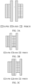
- FIGs. 9A , 9B, 9C, and 9D illustrate that, in some embodiments, within an SSB, the first and last OFDM symbols are used for PSBCH. Comb-like resource mapping is applied to PSBCH on the first and last OFDM symbols. The rest resource elements on the first and last OFDM symbols which are not mapped by PSBCH are left empty.
- FIG. 9A illustrates that, in some embodiments, within an SSB, there are two OFDM symbols used for PSBCH, one OFDM symbol for S-PSS and one OFDM symbol for S-SSS. Within an SSB, the 2nd OFDM symbol is used for S-PSS, the 3rd OFDM symbol is used for S-SSS.
- FIG. 9A illustrates that, in some embodiments, within an SSB, there are two OFDM symbols used for PSBCH, one OFDM symbol for S-PSS and one OFDM symbol for S-SSS. Within an SSB, the 2nd OFDM symbol is used for S-PSS, the 3r
- FIG. 9B illustrates that, in some embodiments, within an SSB, there are three OFDM symbols used for PSBCH, one OFDM symbol for S-PSS and one OFDM symbol for S-SSS. Within an SSB, the 1st, 3rd, 5th OFDM symbols are used for PSBCH, 2nd OFDM symbol for S-PSS, and 4th OFDM symbol are used for S-SSS.
- FIG. 9C illustrates that, in some embodiments, within an SSB, there are four OFDM symbols used for PSBCH, one OFDM symbol for S-PSS and one OFDM symbol for S-SSS.
- FIG. 9D illustrates that, in some embodiments, within an SSB, there are four OFDM symbols used for PSBCH, one OFDM symbol is used for S-PSS and one OFDM symbol is used for S-SSS.
- the 1st, 3rd, 4th, and 6th OFDM symbols are used for PSBCH, 2nd OFDM symbol is used for S-PSS, and 5th OFDM symbol is used for S-SSS.
- FIG. 9A , 9B, 9C, and 9D illustrate that, in some embodiments, the resources used for PSBCH transmission includes the resources used for both PSBCH payload and DMRS.
- the two candidate ways to multiplex DMRS and PSBCH payload, which is illustrated in FIG. 5 are also applicable for FIGs. 9A , 9B, 9C, and 9D .
- One illustration multiplexing between DMRS and PSBCH payload of FIG. 9A is illustrated in FIG. 10 .
- FIGs. 10 One illustration multiplexing between DMRS and PSBCH payload of FIG. 9A is illustrated in FIG. 10 .
- 9A , 9B, 9C, and 9D illustrate that, in some embodiments, if the frequency resource of PSBCH is larger than S-PSS and S-SSS, part of the frequency resource on the OFDM symbols used for S-PSS and/or S-SSS can also be used for PSBCH to align the frequency resource between PSBCH and S-SSS, or between PSBCH and S-PSS.
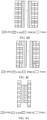
- FIGs. 11A, 11B , 11C, and 11D illustrate that, in some embodiments, within an SSB, the first and last OFDM symbols are used for PSBCH. Comb-like resource mapping is applied to PSBCH on the first and last OFDM symbols. The rest resource elements on the first and last OFDM symbols which are not mapped by PSBCH are left empty.
- Within an SSB there are two adjacent OFDM symbols used for S-PSS, two adjacent OFDM symbols used for S-SSS.
- FIG. 11A illustrates that, in some embodiments, within an SSB, there are two OFDM symbols used for PSBCH.
- S-PSS occupies the 2nd, 3rd OFDM symbols
- S-SSS occupies the 4th and 5th OFDM symbols.
- FIG. 11B illustrates that, in some embodiments, within an SSB, there are three OFDM symbols used for PSBCH. Within an SSB, the 1st, 4th, and 7th OFDM symbols are used for PSBCH, 2nd and 3rd OFDM symbols are used for S-PSS, and 5th and 6th OFDM symbols are used for S-SSS.
- FIG. 11C illustrates that, in some embodiments, within an SSB, there are four OFDM symbols used for PSBCH.
- FIG. 11D illustrates that, in some embodiments, within an SSB, there are four OFDM symbols used for PSBCH.
- the 1st, 4th, 5th, and 8th OFDM symbols are used for PSBCH, 2nd and 3rd OFDM symbols are used for S-PSS, and 6th and 7th OFDM symbols are used for S-SSS.
- 11A, 11B , 11C, and 11D illustrate that, in some embodiments, the resources used for PSBCH transmission include the resources used for both PSBCH payload and DMRS.
- the candidate ways to multiplex DMRS and PSBCH payload which is illustrated in FIG. 5 and/or FIG. 10 , are also applicable for FIGs. 11A, 11B , 11C, and 11D .
- FIGs. 11A, 11B , 11C, and 11D are also applicable for FIGs.
- 11A, 11B , 11C, and 11D illustrate that, in some embodiments, if the frequency resource of PSBCH is larger than S-PSS and S-SSS, part of the frequency resource on the OFDM symbols used for S-PSS and/or S-SSS can also be used for PSBCH to align the frequency resource between PSBCH and S-SSS, or between PSBCH and S-PSS.
- One illustration of mapping PSBCH on S-PSS/S-SSS OFDM symbols of FIG. 11A is illustrated in FIG. 12 .
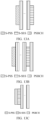
- FIGs. 13A, 13B, and 13C illustrate that, in some embodiments, within an SSB, there is one S-PSS OFDM symbol, one S-SSS OFDM symbol.
- FIG. 13A illustrates that, in some embodiments, a S-PSS OFDM symbol is at the beginning of the SSB, S-SSS OFDM symbol is at the end of the SSB, PSBCH is in between S-PSS and S-SSS, there are more than 1 OFDM symbol for PSBCH.
- FIG. 13A illustrates that, in some embodiments, a S-PSS OFDM symbol is at the beginning of the SSB, S-SSS OFDM symbol is at the end of the SSB, PSBCH is in between S-PSS and S-SSS, there are more than 1 OFDM symbol for PSBCH.
- FIG. 13B illustrates that, in some embodiments, S-PSS OFDM symbol is at the beginning of the SSB, there are more than 1 OFDM symbol for PSBCH, the last OFDM symbol is used for PSBCH, the second last OFDM symbol is used for S-SSS, the rest OFDM symbols of PSBCH are between S-PSS and S-SSS.
- FIG. 13C illustrates that, in some embodiments, the 1st OFDM symbol is used for S-PSS, the 2nd OFDM symbol is used for S-SSS, there are more than 1 OFDM symbol for PSBCH, PSBCH OFDM symbols are after S-SSS OFDM symbol.
- FIG. 13A, 13B, and 13C illustrate that, in some embodiments, there can be one additional OFDM in front of the first OFDM of the SSB that is used as AGC, and/or one additional OFDM symbol after the last OFDM symbol of the SSB that is used as GP.
- FIG. 13A with additional AGC and GP symbols is illustrated in FIG. 14 .
- the AGC symbol can be mapped with PSBCH payload or padding bits. If AGC symbol is mapped with PSBCH payload, it can be comb-like mapped, which is similar as the first OFDM symbol in FIG. 9A .
- the GP symbol can be left empty. Or the GP symbol can be comb-like mapped by PSBCH payload, which is similar as the last OFDM symbol in FIG. 9A , the rest resource elements that are not mapped by PSBCH are left empty.
- the frequency resource of PSBCH is larger than S-PSS and S-SSS, part of the frequency resource on the OFDM symbols used for S-PSS and/or S-SSS can also be used for PSBCH.
- the frequency resource of PSBCH and S-SSS can be aligned, or the frequency resource of PSBCH and S-PSS can be aligned.
- Comb-like resource mapping of S-PSS is onto the first/last OFDM symbol of an SSB.
- Comb-like resource mapping of S-SSS is onto the first/last OFDM symbol of an SSB.
- Comb-like resource mapping of PSBCH is onto the first/last OFDM symbol of an SSB. If S-PSS is comb-like mapped to one OFDM symbol, the rest OFDM symbols used for S-PSS are also comb-like mapped. If S-SSS is comb-like mapped to one OFDM symbol, the rest OFDM symbols used for S-SSS are also comb-like mapped.
- FIG. 15 is a block diagram of an example system 700 for wireless communication according to an embodiment of the present disclosure. Embodiments described herein may be implemented into the system using any suitably configured hardware and/or software.
- FIG. 15 illustrates the system 700 including a radio frequency (RF) circuitry 710, a baseband circuitry 720, an application circuitry 730, a memory/storage 740, a display 750, a camera 760, a sensor 770, and an input/output (I/O) interface 780, coupled with each other at least as illustrated.
- RF radio frequency
- the application circuitry 730 may include a circuitry such as, but not limited to, one or more single-core or multi-core processors.
- the processors may include any combination of general-purpose processors and dedicated processors, such as graphics processors, application processors.
- the processors may be coupled with the memory/storage and configured to execute instructions stored in the memory/storage to enable various applications and/or operating systems running on the system.
- the baseband circuitry 720 may include circuitry such as, but not limited to, one or more single-core or multi-core processors.
- the processors may include a baseband processor.
- the baseband circuitry may handle various radio control functions that enables communication with one or more radio networks via the RF circuitry.
- the radio control functions may include, but are not limited to, signal modulation, encoding, decoding, radio frequency shifting, etc.
- the baseband circuitry may provide for communication compatible with one or more radio technologies.
- the baseband circuitry may support communication with an evolved universal terrestrial radio access network (EUTRAN) and/or other wireless metropolitan area networks (WMAN), a wireless local area network (WLAN), a wireless personal area network (WPAN).
- EUTRAN evolved universal terrestrial radio access network
- WMAN wireless metropolitan area networks
- WLAN wireless local area network
- WPAN wireless personal area network
- Embodiments in which the baseband circuitry is configured to support radio communications of more than one wireless protocol may be referred to as multi-mode baseband circuit
- the baseband circuitry 720 may include circuitry to operate with signals that are not strictly considered as being in a baseband frequency.
- baseband circuitry may include circuitry to operate with signals having an intermediate frequency, which is between a baseband frequency and a radio frequency.
- the RF circuitry 710 may enable communication with wireless networks using modulated electromagnetic radiation through a non-solid medium.
- the RF circuitry may include switches, filters, amplifiers, etc. to facilitate the communication with the wireless network.
- the RF circuitry 710 may include circuitry to operate with signals that are not strictly considered as being in a radio frequency.
- RF circuitry may include circuitry to operate with signals having an intermediate frequency, which is between a baseband frequency and a radio frequency.
- the transmitter circuitry, control circuitry, or receiver circuitry discussed above with respect to the user equipment, eNB, or gNB may be embodied in whole or in part in one or more of the RF circuitry, the baseband circuitry, and/or the application circuitry.
- circuitry may refer to, be part of, or include an application specific integrated circuit (ASIC), an electronic circuit, a processor (shared, dedicated, or group), and/or a memory (shared, dedicated, or group) that execute one or more software or firmware programs, a combinational logic circuit, and/or other suitable hardware components that provide the described functionality.
- the electronic device circuitry may be implemented in, or functions associated with the circuitry may be implemented by, one or more software or firmware modules.
- the constituent components of the baseband circuitry, the application circuitry, and/or the memory/storage may be implemented together on a system on a chip (SOC).
- the memory/storage 740 may be used to load and store data and/or instructions, for example, for system.
- the memory/storage for one embodiment may include any combination of suitable volatile memory, such as dynamic random access memory (DRAM)), and/or non-volatile memory, such as flash memory.
- the I/O interface 780 may include one or more user interfaces designed to enable user interaction with the system and/or peripheral component interfaces designed to enable peripheral component interaction with the system.
- User interfaces may include, but are not limited to a physical keyboard or keypad, a touchpad, a speaker, a microphone, etc.
- Peripheral component interfaces may include, but are not limited to, a non-volatile memory port, a universal serial bus (USB) port, an audio jack, and a power supply interface.
- USB universal serial bus
- the sensor 770 may include one or more sensing devices to determine environmental conditions and/or location information related to the system.
- the sensors may include, but are not limited to, a gyro sensor, an accelerometer, a proximity sensor, an ambient light sensor, and a positioning unit.
- the positioning unit may also be part of, or interact with, the baseband circuitry and/or RF circuitry to communicate with components of a positioning network, e.g., a global positioning system (GPS) satellite.
- GPS global positioning system
- the display 750 may include a display, such as a liquid crystal display and a touch screen display.
- the system 700 may be a mobile computing device such as, but not limited to, a laptop computing device, a tablet computing device, a netbook, an ultrabook, a smartphone, etc.
- system may have more or less components, and/or different architectures.
- methods described herein may be implemented as a computer program.
- the computer program may be stored on a storage medium, such as a non-transitory storage medium.
- Some embodiments of the present disclosure provide user equipment and a method for transmitting a synchronization signal block (SSB) of the same capable of performing vehicle-to-everything (V2X) communication and improving reliability.
- SSB synchronization signal block
- V2X vehicle-to-everything
- the embodiment of the present disclosure is a combination of techniques/processes that can be adopted in 3GPP specification to create an end product.
- the disclosed system, device, and method in the embodiments of the present disclosure can be realized with other ways.
- the above-mentioned embodiments are exemplary only.
- the division of the units is merely based on logical functions while other divisions exist in realization. It is possible that a plurality of units or components are combined or integrated in another system. It is also possible that some characteristics are omitted or skipped.
- the displayed or discussed mutual coupling, direct coupling, or communicative coupling operate through some ports, devices, or units whether indirectly or communicatively by ways of electrical, mechanical, or other kinds of forms.
- the units as separating components for explanation are or are not physically separated.
- the units for display are or are not physical units, that is, located in one place or distributed on a plurality of network units. Some or all of the units are used according to the purposes of the embodiments. Moreover, each of the functional units in each of the embodiments can be integrated in one processing unit, physically independent, or integrated in one processing unit with two or more than two units.
- the software function unit is realized and used and sold as a product, it can be stored in a readable storage medium in a computer.
- the technical plan proposed by the present disclosure can be essentially or partially realized as the form of a software product.
- one part of the technical plan beneficial to the conventional technology can be realized as the form of a software product.
- the software product in the computer is stored in a storage medium, including a plurality of commands for a computational device (such as a personal computer, a server, or a network device) to run all or some of the steps disclosed by the embodiments of the present disclosure.
- the storage medium includes a USB disk, a mobile hard disk, a read-only memory (ROM), a random access memory (RAM), a floppy disk, or other kinds of media capable of storing program codes.
Landscapes
- Engineering & Computer Science (AREA)
- Signal Processing (AREA)
- Computer Networks & Wireless Communication (AREA)
- Databases & Information Systems (AREA)
- Computer Security & Cryptography (AREA)
- Mobile Radio Communication Systems (AREA)
Applications Claiming Priority (3)
| Application Number | Priority Date | Filing Date | Title |
|---|---|---|---|
| US201862739539P | 2018-10-01 | 2018-10-01 | |
| PCT/CN2019/108706 WO2020069659A1 (en) | 2018-10-01 | 2019-09-27 | User equipment and method for transmitting synchronization signal block of same |
| EP19868288.2A EP3841691B1 (de) | 2018-10-01 | 2019-09-27 | Benutzergerät und verfahren zur übertragung eines synchronisierungssignalblocks davon |
Related Parent Applications (2)
| Application Number | Title | Priority Date | Filing Date |
|---|---|---|---|
| EP19868288.2A Division EP3841691B1 (de) | 2018-10-01 | 2019-09-27 | Benutzergerät und verfahren zur übertragung eines synchronisierungssignalblocks davon |
| EP19868288.2A Division-Into EP3841691B1 (de) | 2018-10-01 | 2019-09-27 | Benutzergerät und verfahren zur übertragung eines synchronisierungssignalblocks davon |
Publications (2)
| Publication Number | Publication Date |
|---|---|
| EP4407916A2 true EP4407916A2 (de) | 2024-07-31 |
| EP4407916A3 EP4407916A3 (de) | 2024-10-09 |
Family
ID=70054950
Family Applications (2)
| Application Number | Title | Priority Date | Filing Date |
|---|---|---|---|
| EP24180279.2A Pending EP4407916A3 (de) | 2018-10-01 | 2019-09-27 | Benutzergerät und verfahren zur übertragung eines synchronisationssignalblocks davon |
| EP19868288.2A Active EP3841691B1 (de) | 2018-10-01 | 2019-09-27 | Benutzergerät und verfahren zur übertragung eines synchronisierungssignalblocks davon |
Family Applications After (1)
| Application Number | Title | Priority Date | Filing Date |
|---|---|---|---|
| EP19868288.2A Active EP3841691B1 (de) | 2018-10-01 | 2019-09-27 | Benutzergerät und verfahren zur übertragung eines synchronisierungssignalblocks davon |
Country Status (7)
| Country | Link |
|---|---|
| US (2) | US11121795B2 (de) |
| EP (2) | EP4407916A3 (de) |
| JP (1) | JP7303292B2 (de) |
| KR (1) | KR102602450B1 (de) |
| CN (2) | CN112602275A (de) |
| AU (1) | AU2019352650B2 (de) |
| WO (1) | WO2020069659A1 (de) |
Families Citing this family (10)
| Publication number | Priority date | Publication date | Assignee | Title |
|---|---|---|---|---|
| US20220140967A1 (en) * | 2019-02-14 | 2022-05-05 | Apple Inc. | Design of nr sidelink synchronization signal for enhanced vehicle-to-everything use cases with optimized receiver processing |
| CN114268530B (zh) * | 2019-08-01 | 2023-10-20 | 大唐移动通信设备有限公司 | 一种信号的发送、接收方法、终端及装置 |
| US12219537B2 (en) * | 2019-11-07 | 2025-02-04 | Lg Electronics Inc. | Method and device for obtaining slot information related to S-SSB in NR V2X |
| EP4104546A1 (de) * | 2020-02-14 | 2022-12-21 | Nokia Technologies Oy | Synchronisierungspriorität für drahtlose sidelink-kommunikation |
| WO2021237675A1 (zh) * | 2020-05-29 | 2021-12-02 | Oppo广东移动通信有限公司 | 无线通信方法和终端设备 |
| EP4183225A4 (de) | 2020-07-15 | 2024-05-01 | QUALCOMM Incorporated | Verfahren für den entwurf von synchronisationssignalblockwellenform für sidelink-kommunikationen |
| US20220077922A1 (en) * | 2020-09-09 | 2022-03-10 | Qualcomm Incorporated | Synchronization signal block forwarding |
| WO2022062822A1 (en) * | 2020-09-24 | 2022-03-31 | Qualcomm Incorporated | Network assisted initial access for holographic mimo |
| US11722993B2 (en) * | 2021-03-23 | 2023-08-08 | Qualcomm Incorporated | Techniques for configuring resources in a sidelink resource pool |
| WO2024109168A1 (en) * | 2023-08-09 | 2024-05-30 | Lenovo (Beijing) Limited | Methods and apparatuses for transmissions over sidelink in unlicensed spectra |
Family Cites Families (12)
| Publication number | Priority date | Publication date | Assignee | Title |
|---|---|---|---|---|
| CN105981454B (zh) * | 2014-01-26 | 2019-11-15 | Lg电子株式会社 | 在支持设备到设备通信的无线通信系统中发送同步信号和同步信道的方法及其装置 |
| KR102450241B1 (ko) * | 2014-09-02 | 2022-10-04 | 엘지전자 주식회사 | 무선 통신 시스템에서 장치 대 장치 단말의 동기 신호 전송 방법 및 장치 |
| KR102373038B1 (ko) * | 2015-05-06 | 2022-03-11 | 삼성전자 주식회사 | 기기 대 기기 무선 통신에서 신호 수신 방법 및 장치 |
| US10708874B2 (en) * | 2015-08-19 | 2020-07-07 | Sony Corporation | Mobile communications devices and methods |
| WO2017222206A1 (ko) * | 2016-06-22 | 2017-12-28 | 엘지전자 주식회사 | V2x 통신을 위한 온/오프 파워 타임 마스크를 적용하는 방법 및 단말 |
| BR112019019607A2 (pt) * | 2017-03-24 | 2020-04-22 | Ericsson Telefon Ab L M | método para sincronização em um sistema de comunicação sem fio, dispositivo sem fio, dispositivo terminal, meio de armazenamento lido por computador e sistema de comunicações |
| WO2019216627A1 (ko) * | 2018-05-09 | 2019-11-14 | 엘지전자 주식회사 | Nr v2x에서 사이드링크 단말이 전송 파라미터를 조정하는 방법 및 장치 |
| WO2019240548A1 (en) * | 2018-06-14 | 2019-12-19 | Lg Electronics Inc. | Method and apparatus for performing sidelink communication by ue in nr v2x |
| EP3796733B1 (de) * | 2018-07-17 | 2023-03-22 | LG Electronics Inc. | Verfahren und vorrichtung zur bestimmung von tbs in nr v2x |
| US11546922B2 (en) * | 2018-08-03 | 2023-01-03 | Lg Electronics Inc. | Method and device for performing power control in NR V2X |
| KR102591922B1 (ko) * | 2018-08-10 | 2023-10-20 | 베이징 시아오미 모바일 소프트웨어 컴퍼니 리미티드 | 기준 신호 전송 방법 및 장치, 기준 신호 수신 방법 및 장치, 차량 탑재 장치, 및 단말기 |
| US20210360549A1 (en) * | 2018-09-20 | 2021-11-18 | Lg Electronics Inc. | Method and terminal for transmitting and receiving signal in wireless communication system |
-
2019
- 2019-09-27 AU AU2019352650A patent/AU2019352650B2/en active Active
- 2019-09-27 JP JP2021517832A patent/JP7303292B2/ja active Active
- 2019-09-27 EP EP24180279.2A patent/EP4407916A3/de active Pending
- 2019-09-27 CN CN201980055277.5A patent/CN112602275A/zh active Pending
- 2019-09-27 KR KR1020217009720A patent/KR102602450B1/ko active Active
- 2019-09-27 WO PCT/CN2019/108706 patent/WO2020069659A1/en not_active Ceased
- 2019-09-27 EP EP19868288.2A patent/EP3841691B1/de active Active
- 2019-09-27 CN CN202110413050.2A patent/CN113115258B/zh active Active
-
2021
- 2021-03-17 US US17/204,719 patent/US11121795B2/en active Active
- 2021-08-11 US US17/399,798 patent/US11658761B2/en active Active
Also Published As
| Publication number | Publication date |
|---|---|
| JP2022501970A (ja) | 2022-01-06 |
| CN112602275A (zh) | 2021-04-02 |
| KR102602450B1 (ko) | 2023-11-14 |
| JP7303292B2 (ja) | 2023-07-04 |
| US20210376945A1 (en) | 2021-12-02 |
| KR20210042410A (ko) | 2021-04-19 |
| CN113115258A (zh) | 2021-07-13 |
| AU2019352650B2 (en) | 2022-06-02 |
| WO2020069659A1 (en) | 2020-04-09 |
| EP3841691A1 (de) | 2021-06-30 |
| US20210203429A1 (en) | 2021-07-01 |
| CN113115258B (zh) | 2022-11-29 |
| AU2019352650A1 (en) | 2021-04-29 |
| US11658761B2 (en) | 2023-05-23 |
| EP3841691B1 (de) | 2024-07-17 |
| EP3841691A4 (de) | 2021-11-03 |
| EP4407916A3 (de) | 2024-10-09 |
| US11121795B2 (en) | 2021-09-14 |
Similar Documents
| Publication | Publication Date | Title |
|---|---|---|
| US11121795B2 (en) | User equipment and method for transmitting synchronization signal block of same | |
| EP4254850B1 (de) | Benutzergerät und verfahren zur ressourcenübertragung | |
| US12052198B2 (en) | Apparatus and method of wireless communication of same | |
| US11343821B2 (en) | Method and apparatus for performing resource scheduling and delivering control information in vehicle-to-everything communication system | |
| WO2021098305A1 (en) | Apparatus and method for transmitting or receiving physical sidelink broadcast channel | |
| EP3977795B1 (de) | Vorrichtung und verfahren zur drahtlosen kommunikation | |
| EP4059169B1 (de) | Vorrichtung und verfahren zur drahtlosen kommunikation | |
| WO2021110109A1 (en) | Apparatus and method of wireless communication |
Legal Events
| Date | Code | Title | Description |
|---|---|---|---|
| PUAI | Public reference made under article 153(3) epc to a published international application that has entered the european phase |
Free format text: ORIGINAL CODE: 0009012 |
|
| STAA | Information on the status of an ep patent application or granted ep patent |
Free format text: STATUS: THE APPLICATION HAS BEEN PUBLISHED |
|
| AC | Divisional application: reference to earlier application |
Ref document number: 3841691 Country of ref document: EP Kind code of ref document: P |
|
| AK | Designated contracting states |
Kind code of ref document: A2 Designated state(s): AL AT BE BG CH CY CZ DE DK EE ES FI FR GB GR HR HU IE IS IT LI LT LU LV MC MK MT NL NO PL PT RO RS SE SI SK SM TR |
|
| REG | Reference to a national code |
Ref country code: DE Ref legal event code: R079 Free format text: PREVIOUS MAIN CLASS: H04L0005000000 Ipc: H04J0011000000 |
|
| PUAL | Search report despatched |
Free format text: ORIGINAL CODE: 0009013 |
|
| AK | Designated contracting states |
Kind code of ref document: A3 Designated state(s): AL AT BE BG CH CY CZ DE DK EE ES FI FR GB GR HR HU IE IS IT LI LT LU LV MC MK MT NL NO PL PT RO RS SE SI SK SM TR |
|
| RIC1 | Information provided on ipc code assigned before grant |
Ipc: H04L 5/00 20060101ALI20240905BHEP Ipc: H04J 11/00 20060101AFI20240905BHEP |
|
| STAA | Information on the status of an ep patent application or granted ep patent |
Free format text: STATUS: REQUEST FOR EXAMINATION WAS MADE |
|
| 17P | Request for examination filed |
Effective date: 20250326 |
|
| STAA | Information on the status of an ep patent application or granted ep patent |
Free format text: STATUS: EXAMINATION IS IN PROGRESS |