EP4407847A1 - Motorvorrichtung und baumaschine - Google Patents
Motorvorrichtung und baumaschine Download PDFInfo
- Publication number
- EP4407847A1 EP4407847A1 EP22872660.0A EP22872660A EP4407847A1 EP 4407847 A1 EP4407847 A1 EP 4407847A1 EP 22872660 A EP22872660 A EP 22872660A EP 4407847 A1 EP4407847 A1 EP 4407847A1
- Authority
- EP
- European Patent Office
- Prior art keywords
- stator
- motor device
- cavity
- rotor
- fan
- Prior art date
- Legal status (The legal status is an assumption and is not a legal conclusion. Google has not performed a legal analysis and makes no representation as to the accuracy of the status listed.)
- Pending
Links
Images


Classifications
-
- H—ELECTRICITY
- H02—GENERATION; CONVERSION OR DISTRIBUTION OF ELECTRIC POWER
- H02K—DYNAMO-ELECTRIC MACHINES
- H02K9/00—Arrangements for cooling or ventilating
- H02K9/14—Arrangements for cooling or ventilating wherein gaseous cooling medium circulates between the machine casing and a surrounding mantle
- H02K9/16—Arrangements for cooling or ventilating wherein gaseous cooling medium circulates between the machine casing and a surrounding mantle wherein the cooling medium circulates through ducts or tubes within the casing
-
- E—FIXED CONSTRUCTIONS
- E02—HYDRAULIC ENGINEERING; FOUNDATIONS; SOIL SHIFTING
- E02F—DREDGING; SOIL-SHIFTING
- E02F9/00—Component parts of dredgers or soil-shifting machines, not restricted to one of the kinds covered by groups E02F3/00 - E02F7/00
-
- E—FIXED CONSTRUCTIONS
- E02—HYDRAULIC ENGINEERING; FOUNDATIONS; SOIL SHIFTING
- E02F—DREDGING; SOIL-SHIFTING
- E02F9/00—Component parts of dredgers or soil-shifting machines, not restricted to one of the kinds covered by groups E02F3/00 - E02F7/00
- E02F9/08—Superstructures; Supports for superstructures
- E02F9/0858—Arrangement of component parts installed on superstructures not otherwise provided for, e.g. electric components, fenders, air-conditioning units
- E02F9/0866—Engine compartment, e.g. heat exchangers, exhaust filters, cooling devices, silencers, mufflers, position of hydraulic pumps in the engine compartment
-
- H—ELECTRICITY
- H02—GENERATION; CONVERSION OR DISTRIBUTION OF ELECTRIC POWER
- H02K—DYNAMO-ELECTRIC MACHINES
- H02K1/00—Details of the magnetic circuit
- H02K1/06—Details of the magnetic circuit characterised by the shape, form or construction
- H02K1/22—Rotating parts of the magnetic circuit
- H02K1/27—Rotor cores with permanent magnets
- H02K1/2706—Inner rotors
- H02K1/272—Inner rotors the magnetisation axis of the magnets being perpendicular to the rotor axis
- H02K1/274—Inner rotors the magnetisation axis of the magnets being perpendicular to the rotor axis the rotor consisting of two or more circumferentially positioned magnets
- H02K1/2753—Inner rotors the magnetisation axis of the magnets being perpendicular to the rotor axis the rotor consisting of two or more circumferentially positioned magnets the rotor consisting of magnets or groups of magnets arranged with alternating polarity
- H02K1/278—Surface mounted magnets; Inset magnets
- H02K1/2783—Surface mounted magnets; Inset magnets with magnets arranged in Halbach arrays
-
- H—ELECTRICITY
- H02—GENERATION; CONVERSION OR DISTRIBUTION OF ELECTRIC POWER
- H02K—DYNAMO-ELECTRIC MACHINES
- H02K21/00—Synchronous motors having permanent magnets; Synchronous generators having permanent magnets
- H02K21/12—Synchronous motors having permanent magnets; Synchronous generators having permanent magnets with stationary armatures and rotating magnets
- H02K21/14—Synchronous motors having permanent magnets; Synchronous generators having permanent magnets with stationary armatures and rotating magnets with magnets rotating within the armatures
-
- H—ELECTRICITY
- H02—GENERATION; CONVERSION OR DISTRIBUTION OF ELECTRIC POWER
- H02K—DYNAMO-ELECTRIC MACHINES
- H02K3/00—Details of windings
- H02K3/04—Windings characterised by the conductor shape, form or construction, e.g. with bar conductors
-
- H—ELECTRICITY
- H02—GENERATION; CONVERSION OR DISTRIBUTION OF ELECTRIC POWER
- H02K—DYNAMO-ELECTRIC MACHINES
- H02K9/00—Arrangements for cooling or ventilating
- H02K9/10—Arrangements for cooling or ventilating by gaseous cooling medium flowing in closed circuit, a part of which is external to the machine casing
-
- H—ELECTRICITY
- H02—GENERATION; CONVERSION OR DISTRIBUTION OF ELECTRIC POWER
- H02K—DYNAMO-ELECTRIC MACHINES
- H02K9/00—Arrangements for cooling or ventilating
- H02K9/22—Arrangements for cooling or ventilating by solid heat conducting material embedded in, or arranged in contact with, the stator or rotor, e.g. heat bridges
- H02K9/227—Heat sinks
Definitions
- the present invention relates to a drive technique using an electric motor.
- an electric construction machine driven by an electric motor hereinafter, also referred to as a motor
- a hybrid construction machine in which both a hydraulic device and an electric motor are used hereinafter, also collectively referred to as electric construction machines.
- An actuator that directly drives each drive unit of an electric construction machine by means of a mechanical element, such as a ball screw, driven by the rotational power of a motor is called an electro-mechanical actuator (EMA).
- EMA electro-mechanical actuator
- EHA electro-hydrostatic actuator
- Patent Literature 1 Japanese Translation of PCT International Application Publication No. 2020-502990
- the present invention has been made in view of such a situation, and a purpose thereof is to provide a motor device that can be properly cooled even in a harsh environment.
- a motor device includes: a stator that includes a coil that becomes an electromagnet when energized; a rotor that includes a permanent magnet facing one surface of the coil and that is provided rotatably with respect to the stator; a housing that houses the stator and the rotor in a sealed manner and that includes end spaces located respectively at both ends of a rotating shaft of the rotor and also includes a cavity communicating with the end spaces and provided on the other surface side of the coil; and a fan that makes a gas in the housing to flow through a cooling flow path constituted by a gap communicating with the end spaces and provided between the one surface and the permanent magnet, the end spaces, and the cavity.
- a cooling flow path constituted by the gap between the stator and the rotor, the end spaces, and a cavity is formed within the sealed housing, a coil of the stator can be properly cooled even in a harsh environment where dirt or mud may adhere to the outside of the housing.
- an electric construction machine employing a motor device of the present invention will be described as an example; however, the objects to which the present invention is applicable are not limited to electric construction machines.
- the construction machine includes: an undercarriage capable of traveling on the ground; a rotating superstructure rotatably mounted on the undercarriage; a boom attached to the rotating superstructure such that the boom can be raised and lowered; an arm attached to the boom such as to be bendable; a bucket attached to the arm such as to be bendable; and a motor device that drives at least one of the undercarriage or the bucket.
- the motor device includes: a stator that includes a coil that becomes an electromagnet when energized; a rotor that includes a permanent magnet facing one surface of the coil and that is provided rotatably with respect to the stator; a housing that houses the stator and the rotor in a sealed manner and that includes end spaces located respectively at both ends of a rotating shaft of the rotor and also includes a cavity communicating with the end spaces and provided on the other surface side of the coil; and a fan that makes a gas in the housing to flow through a cooling flow path constituted by a gap communicating with the end spaces and provided between the one surface and the permanent magnet, the end spaces, and the cavity.
- a motor device can be properly cooled even in a harsh environment.
- a motor device or a drive device of the present invention is applicable to an arbitrary device or machine that includes a drive unit or a movable part driven to rotate by a motor. Therefore, the apparatus or device to which the present invention is applicable is not particularly limited.
- the present embodiment describes an electric construction machine that includes multiple drive units, which each are driven by an actuator equipped with a motor and a reducer.
- the present embodiment describes, as an example of the actuator, an EMA that directly drives each drive unit of an electric construction machine by means of a mechanical element driven by the rotational power of a motor.
- the present invention is also applicable to an EHA that indirectly drives each drive unit of an electric construction machine by means of a hydraulic device driven by the rotational power of a motor.
- FIG. 1 is a schematic configuration diagram of an electric construction machine 100.
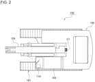
- FIG. 2 is a top view of the electric construction machine 100.
- the orientation such as the front, rear, up, down, left, right, or the like is the same as the orientation of the electric construction machine 100.
- the front of the traveling direction of the electric construction machine 100 will be simply referred to as the front
- the rear of the traveling direction of the electric construction machine 100 will be simply referred to as the rear.
- the upper side of the gravity direction will be simply referred to as the upper side
- the lower side of the gravity direction will be simply referred to as the lower side.
- the right side of a vehicle width direction will be simply referred to as the right side
- the left side of a vehicle width direction will be simply referred to as the left side.
- a rotating superstructure 102 is rotatably mounted on an undercarriage 101 that can travel forward and backward on the ground.
- a cab 103 is provided on the front left side, and a boom 104 is attached in a front center part such that it can be raised and lowered.
- an arm 105 is attached such that it can be bent up and down.
- a bucket 106 is attached such that it can be bent up and down.
- a gyro sensor 110 is attached to the front left side of the cab 103.
- the gyro sensor 110 is attached at a position maximally distant from the center C1 of rotation.
- the gyro sensor 110 is a sensor that can detect the inclination angle, inclination direction, rotating position, and rotational angular velocity of the cab 103 (or the undercarriage 101 or rotating superstructure 102).
- the inclination direction means the upward or downward direction of inclination.
- the undercarriage 101, rotating superstructure 102, boom 104, arm 105, and bucket 106 will be collectively referred to as drive units of the electric construction machine 100. Therefore, the electric construction machine 100 illustrated in FIGS. 1 and 2 is a construction machine that includes five drive units.
- the undercarriage 101 constitutes a traveling section that can travel on the ground
- the rotating superstructure 102 constitutes a rotating section that can rotate with respect to the traveling section
- the boom 104, arm 105, and bucket 106 constitute a work section attached to the rotating section to perform work.
- Each actuator as a drive device for driving each drive unit of the electric construction machine 100 includes: an inverter that converts DC electricity from a DC power source, such as a battery, into AC electricity; a motor device that generates rotational power based on the AC electricity supplied from the inverter; and a reducer that decelerates the rotation of the motor device and obtains torque corresponding to the reduction ratio.
- a DC power source such as a battery
- a motor device that generates rotational power based on the AC electricity supplied from the inverter
- a reducer that decelerates the rotation of the motor device and obtains torque corresponding to the reduction ratio.
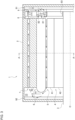
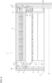
- FIG. 3 is a sectional view of a motor device 1 including a rotational axis O
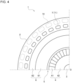
- FIG. 4 is a sectional view of the motor device 1 at a cross section taken along line A-A in FIG. 3 , which is perpendicular to the rotational axis O.
- the motor device 1 includes: a housing 2 that houses therein the following constituting components of the motor device 1 in a sealed manner; a shaft member 3 that is provided rotatably around the rotational axis O and that outputs rotational power from the tip (the left end in FIG.
- a rotor 4 that is fixed to the shaft member 3 and rotatable in conjunction with the shaft member 3; a stator 6 fixed to the housing 2 and facing the rotor 4 across a gap 5 as a gap in a radial direction (vertical direction in FIG. 3 ); a cavity 7 that is provided on the back side of the stator 6, i.e., the side opposite to the surface of the stator 6 facing the rotor 4 and the gap 5, and that allows a cooling gas to flow therein; a fan 8 that is connected or fixed to a base end (the right end in FIG.
- the rotor 4 includes multiple permanent magnets 41 arranged periodically along a circumferential direction or a rotational direction around the rotational axis O, and a support member 42 that interconnects the multiple permanent magnets 41.
- the multiple permanent magnets 41 are provided to face the gap 5 between the permanent magnets 41 and the stator 6 and are connected by the support member 42 on the opposite side.
- the support member 42 is formed of a soft magnetic material with high magnetic permeability, such as iron, carbon steel, silicon steel, permalloy, sendust, permendur, soft ferrite, amorphous magnetic alloy, and nanocrystalline magnetic alloy.
- the support member 42 containing iron is also called a yoke.
- the support member 42 may be also formed of a non-magnetic material.
- the multiple permanent magnets 41 are arranged such that the magnetic poles appear periodically along a circumferential direction, on the surface facing the stator 6.
- the multiple permanent magnets 41 may be arranged such that the N pole and the S pole alternately appear along a circumferential direction on the surface facing the stator 6, or the multiple permanent magnets 41 may be arranged according to a Halbach array as shown in FIG. 5 .
- a Halbach array is an array in which the magnetic pole direction of each permanent magnet 41 is rotated from the magnetic pole direction of a permanent magnet 41 adjacent thereto along a circumferential direction, by one of N equal parts of 2 ⁇ (N is an integer greater than or equal to 3 or less than or equal to -3).
- N 4
- n/2 i.e. 90 degrees
- the stator 6 includes multiple coils 61 arranged along a circumferential direction, which become electromagnets when energized, and a yoke 62 that interconnects the multiple coils 61. As illustrated in FIG. 5 , the multiple coils 61 are arranged at equal intervals along the rotational direction or a circumferential direction of the motor device 1, and one surface or end surface (the inner end surface in FIG. 5 or the lower end surface in FIG. 3 ) of each of the multiple coils 61 faces the multiple permanent magnets 41 of the rotor 4 across the gap 5.
- the yoke 62 is formed of a soft magnetic material containing iron.
- the stator 6 by making the stator 6 to have a coreless structure, the radial thickness of each coil 61 can be reduced, so that the gap 5 between the stator 6 and the rotor 4 can be made larger. This can increase the amount of cooling gas flowing through the gap 5, thereby further improving the cooling efficiency.
- a cavity 7 provided in the housing 2 is located on the side of the other surface or end surface (the upper surface in FIG. 3 ) of each coil 61 to face the yoke 62, and the cooling gas, which flows through the gap 5 between the one end surface (the lower surface in FIG. 3 ) of each coil 61 and the permanent magnets 41, can also flow through the cavity 7.
- the gap 5 and the cavity 7 are provided parallel to each other along the rotational axis O of the rotor 4, and the cooling gas flows through the gap 5 and the cavity 7 in directions opposite to each other along the rotational axis O. That is, the cooling gas in the gap 5 flows from the base end side of the shaft member 3 (the right side in FIG.
- a tip end space 10 is provided as an end space that communicates with the gap 5 and the cavity 7, and the direction of the cooling gas flowing out of the gap 5 to the left is diverted by the inner wall of the housing 2 or a tip side heat dissipation unit 92, which will be described later, such that the cooling gas flows to the right into the cavity 7.
- a base end space 11 is provided as an end space that also communicates with the gap 5 and the cavity 7.
- a fan 8 is provided to make the cooling gas to flow or circulate within the housing 2, and the direction of the cooling gas flowing out of the cavity 7 to the right is diverted such that the cooling gas flows to the left into the gap 5.
- the gap 5 on one end surface side of a coil 61, the cavity 7 on the other end surface side of the coil 61, and the tip end space 10 and the base end space 11 communicating with the gap 5 and the cavity 7 can form a cooling flow path, through which air as the cooling gas circulates, such as to surround the coil 61 that generates heat when energized while the motor device 1 is driven to rotate. Therefore, the coil 61 can be efficiently cooled.
- the flowing directions of the cooling gas flowing through the gap 5 and the cavity 7 along the rotational axis O may be opposite to those shown in FIG. 3 . That is, the cooling gas in the cavity 7 may flow from the base end side of the shaft member 3 (the right side in FIG. 3 ) to the left toward the tip side (the left side in FIG.
- the cooling gas in the gap 5 may flow from the tip side of the shaft member 3 to the right toward the base end side.
- Such a circulation direction of the cooling gas can be adjusted by the fan 8, the heat dissipation unit 9, or the both, as will be described later.
- the cavity 7 in FIG. 3 is formed linearly to be parallel to the rotational axis O and the gap 5, the cavity 7 may be formed in an arbitrary direction as long as it communicates with the spaces on the tip side and the base end side of the shaft member 3 to allow the cooling gas to circulate.
- the cavity 7 may be formed in a curved or spiral shape that meanders and communicates with the spaces on the tip side and the base end side of the shaft member 3. With such a cavity 7, the distance over which the cooling gas flows while in thermal contact with the stator 6 is increased, so that the cooling efficiency can be improved.
- multiple cavities 7 are provided to surround the end surface (the other end surface) on the yoke 62 side of the stator 6.
- the thermal contact area between the cooling gas and the stator 6 may be increased by providing multiple cavities 71 and 72 at multiple positions where the distances from the rotational axis O are different. As illustrated, the farther from the rotational axis O, the larger the cross-sectional area of the cavity (72) can be made, thereby reducing thermal resistance.
- outer cavities 72 are indicated by dotted lines in FIG. 4 , and, with inner cavities 71 closer to the rotational axis O and the outer cavities 72 farther from the rotational axis O, a lattice-shaped or mesh-shaped cooling flow path network is formed outside the stator 6.
- the fan 8 rotates in conjunction with the shaft member 3 and the rotor 4 on the base end side of the rotational axis O (the right end side in FIG. 3 ) and generates a flow of cooling gas in the gap 5 and a cavity 7.
- the fan 8 includes a first fan 81 that faces one end (the right end in FIG. 3 ) of the gap 5 and generates a flow of cooling gas in the gap 5, and a second fan 82 that faces one end (the right end in FIG. 3 ) of a cavity 7 and generates a flow of cooling gas in the cavity 7.
- the first fan 81 and the second fan 82 send the cooling gas in directions opposite to each other along the rotational axis O. In the example of FIG.
- the first fan 81 sends the cooling gas to the left toward the gap 5, and the second fan 82 sends the cooling gas rightward away from the cavity 7.
- the first fan 81 blows the cooling gas into the gap 5, and the second fan 82 draws the cooling gas out of the cavity 7.
- the direction in which each of the fans 81 and 82 sends the cooling gas is determined by the installation direction or inclination direction of the blades. As schematically indicated by the diagonal lines in each of the fans 81 and 82 of FIG. 3 , the installation directions or inclination directions of the blades of the first fan 81 and the second fan 82 are opposite to each other.
- the heat dissipation unit 9 includes the base end side heat dissipation unit 91 fixed to the end surface (the right end surface in FIG. 3 ) or inner wall on the based end side of the rotational axis O in the housing 2, and the tip side heat dissipation unit 92 fixed to the end surface (the left end surface in FIG. 3 ) or inner wall on the tip side of the rotational axis O in the housing 2.
- Each of the heat dissipation units 91 and 92 is formed of a material with low thermal resistance, such as aluminum, and efficiently absorbs, through its uneven surface shape such as fins, heat stored in the cooling gas and releases, from its back surface, the heat outside the housing 2.
- each of the heat dissipation units 91 and 92 it may be preferable to change the direction of the unevenness formation in the surface shape of each of the heat dissipation units 91 and 92 so that air will naturally flows in the air circulation direction shown in FIG. 3 , i.e., the direction from the top (outside) to the bottom (inside) in the base end side heat dissipation unit 91 and the direction from the bottom (inside) to the top (outside) in the tip side heat dissipation unit 92.
- the motor device 1 configured as described above is driven to rotate, the rotor 4, shaft member 3, and fan 8 rotate integrally with respect to the stator 6 and housing 2 as the rotating magnetic field is developed by the multiple energized coils 61 of the stator 6.
- the fan 8 rotates, a circulating cooling flow path of the cooling gas through the gap 5 and a cavity 7 is formed, as indicated by the arrows in FIG. 3 , so that the coils 61 that have been energized and have generated heat are efficiently cooled.
- the heat stored in the cooling gas is efficiently released outside the housing 2 by the heat dissipation unit 9 provided on a circulating cooling flow path of the cooling gas.
- the motor device 1 of the present embodiment may be suitably applied to the undercarriage 101 and the bucket 106 to which dirt or mud is likely to adhere.
- each drive unit of the electric construction machine 100 may be indirectly driven by the motor device 1.
- the actuator may be configured as an EHA by using the motor device 1 to control a hydraulic valve used to control the oil pressure to each hydraulic device.
- cooling gas Although air is used as an example of the cooling gas in the embodiment, other gases may be used as the cooling gas.
- the rotor 4 is provided on the inside (lower side), and the stator 6 is provided on the outside, as illustrated in FIG. 3 ; however, the rotor 4 may be provided on the outside, and the stator 6 may be provided on the inside. In this case, a cavity 7 is formed on the inside of the stator 6.
- each device described in the embodiment can be implemented by hardware resources, software resources, or cooperation between hardware resources and software resources.
- hardware resources processors, ROMs, RAMs, or other LSIs can be employed.
- software resources programs, such as operating system programs and application programs, can be employed.
- the present invention relates to a drive technique using an electric motor.
Landscapes
- Engineering & Computer Science (AREA)
- Power Engineering (AREA)
- Mining & Mineral Resources (AREA)
- Civil Engineering (AREA)
- General Engineering & Computer Science (AREA)
- Structural Engineering (AREA)
- Motor Or Generator Cooling System (AREA)
Applications Claiming Priority (2)
| Application Number | Priority Date | Filing Date | Title |
|---|---|---|---|
| JP2021153846 | 2021-09-22 | ||
| PCT/JP2022/032757 WO2023047904A1 (ja) | 2021-09-22 | 2022-08-31 | モータ装置、建設機械 |
Publications (2)
| Publication Number | Publication Date |
|---|---|
| EP4407847A1 true EP4407847A1 (de) | 2024-07-31 |
| EP4407847A4 EP4407847A4 (de) | 2025-08-27 |
Family
ID=85720495
Family Applications (1)
| Application Number | Title | Priority Date | Filing Date |
|---|---|---|---|
| EP22872660.0A Pending EP4407847A4 (de) | 2021-09-22 | 2022-08-31 | Motorvorrichtung und baumaschine |
Country Status (5)
| Country | Link |
|---|---|
| US (1) | US20240235327A1 (de) |
| EP (1) | EP4407847A4 (de) |
| JP (1) | JP7763846B2 (de) |
| CN (1) | CN118020235A (de) |
| WO (1) | WO2023047904A1 (de) |
Family Cites Families (11)
| Publication number | Priority date | Publication date | Assignee | Title |
|---|---|---|---|---|
| JPS589063U (ja) * | 1981-07-10 | 1983-01-20 | 株式会社東芝 | 乾式液中回転電機 |
| US4908538A (en) * | 1989-02-28 | 1990-03-13 | Geberth John Daniel Jun | Totally enclosed electric motor |
| WO2002015229A1 (en) * | 2000-08-10 | 2002-02-21 | John Floresta | High performance slotless electric motor and method for making same |
| JP4187606B2 (ja) | 2003-08-07 | 2008-11-26 | 川崎重工業株式会社 | 電動機 |
| JP5231059B2 (ja) * | 2008-03-26 | 2013-07-10 | ナブテスコ株式会社 | 油圧ポンプユニット |
| JP5341005B2 (ja) * | 2010-03-29 | 2013-11-13 | 日立建機株式会社 | 建設機械 |
| JP5247848B2 (ja) * | 2011-03-31 | 2013-07-24 | 株式会社小松製作所 | 建設機械 |
| CN103636103B (zh) * | 2011-06-30 | 2015-07-29 | 株式会社日立制作所 | 旋转电机 |
| JP2017060319A (ja) | 2015-09-17 | 2017-03-23 | Ntn株式会社 | 電動機の冷却構造。 |
| DE102016203945A1 (de) * | 2016-03-10 | 2017-09-14 | Siemens Aktiengesellschaft | Statoreinrichtung für eine elektrische Maschine und Verfahren zu deren Herstellung |
| EP3518385B1 (de) * | 2018-01-12 | 2023-03-01 | Carrier Corporation | Kernlose elektromagnetische maschine mit doppelrotor |
-
2022
- 2022-08-31 EP EP22872660.0A patent/EP4407847A4/de active Pending
- 2022-08-31 JP JP2023549440A patent/JP7763846B2/ja active Active
- 2022-08-31 WO PCT/JP2022/032757 patent/WO2023047904A1/ja not_active Ceased
- 2022-08-31 CN CN202280063634.4A patent/CN118020235A/zh active Pending
-
2024
- 2024-03-21 US US18/612,320 patent/US20240235327A1/en active Pending
Also Published As
| Publication number | Publication date |
|---|---|
| CN118020235A (zh) | 2024-05-10 |
| JPWO2023047904A1 (de) | 2023-03-30 |
| EP4407847A4 (de) | 2025-08-27 |
| US20240235327A1 (en) | 2024-07-11 |
| JP7763846B2 (ja) | 2025-11-04 |
| WO2023047904A1 (ja) | 2023-03-30 |
Similar Documents
| Publication | Publication Date | Title |
|---|---|---|
| CN105122606B (zh) | 旋转电机 | |
| EP2573914A2 (de) | Elektromotor | |
| JP5250692B2 (ja) | 永久磁石式回転電機 | |
| JP2019531044A (ja) | 内部冷却システムを有する密閉型回転電気機械 | |
| CN103023217B (zh) | 大功率高速永磁同步电机的整机风路结构 | |
| WO2012093670A1 (ja) | 磁気ギヤ及びそれを有する回転機 | |
| US20210194303A1 (en) | Rotor of a Permanent-Magnet Dynamoelectric Rotary Machine | |
| CN112953309A (zh) | 永磁同步磁悬浮电机 | |
| JP4928986B2 (ja) | 車両駆動用全閉型電動機 | |
| CN107591952B (zh) | 一种可变位置磁悬浮直驱电机结构总成 | |
| EP4407847A1 (de) | Motorvorrichtung und baumaschine | |
| CN110649729A (zh) | 一种多励磁单极游标永磁电机 | |
| CN120377582A (zh) | 磁悬浮风扇散热装置、磁悬浮电机及磁悬浮设备 | |
| CN115589089B (zh) | 一种磁悬浮盘式电机 | |
| JP4939905B2 (ja) | 車両用駆動装置 | |
| CN120377581A (zh) | 集成风冷散热装置的磁悬浮电机及磁悬浮设备 | |
| CN114759760A (zh) | 一种磁-气混合悬浮式直线电机 | |
| CN214674767U (zh) | 散热型磁力滚筒 | |
| CN113131675B (zh) | 飞轮转子的散热机构 | |
| KR20140066880A (ko) | 하이브리드 차량용 구동모터 방열장치 | |
| JP4923238B2 (ja) | 磁気反発支持回転機 | |
| CN222052717U (zh) | 一种表贴式永磁电机转子结构及永磁电机 | |
| TW202120803A (zh) | 風扇 | |
| CN211351971U (zh) | 旋转电机 | |
| CN222301590U (zh) | 内置散热系统的高速直线电机 |
Legal Events
| Date | Code | Title | Description |
|---|---|---|---|
| STAA | Information on the status of an ep patent application or granted ep patent |
Free format text: STATUS: THE INTERNATIONAL PUBLICATION HAS BEEN MADE |
|
| PUAI | Public reference made under article 153(3) epc to a published international application that has entered the european phase |
Free format text: ORIGINAL CODE: 0009012 |
|
| STAA | Information on the status of an ep patent application or granted ep patent |
Free format text: STATUS: REQUEST FOR EXAMINATION WAS MADE |
|
| 17P | Request for examination filed |
Effective date: 20240416 |
|
| AK | Designated contracting states |
Kind code of ref document: A1 Designated state(s): AL AT BE BG CH CY CZ DE DK EE ES FI FR GB GR HR HU IE IS IT LI LT LU LV MC MK MT NL NO PL PT RO RS SE SI SK SM TR |
|
| DAV | Request for validation of the european patent (deleted) | ||
| DAX | Request for extension of the european patent (deleted) | ||
| REG | Reference to a national code |
Ref country code: DE Ref legal event code: R079 Free format text: PREVIOUS MAIN CLASS: H02K0009060000 Ipc: H02K0001278300 |
|
| A4 | Supplementary search report drawn up and despatched |
Effective date: 20250728 |
|
| RIC1 | Information provided on ipc code assigned before grant |
Ipc: H02K 1/2783 20220101AFI20250722BHEP Ipc: H02K 3/04 20060101ALI20250722BHEP Ipc: H02K 9/10 20060101ALI20250722BHEP Ipc: H02K 9/22 20060101ALI20250722BHEP Ipc: H02K 21/14 20060101ALI20250722BHEP |