EP4407291A2 - Probenträger und probenkühlsysteme für die kryoelektronenmikroskopie - Google Patents
Probenträger und probenkühlsysteme für die kryoelektronenmikroskopie Download PDFInfo
- Publication number
- EP4407291A2 EP4407291A2 EP24181409.4A EP24181409A EP4407291A2 EP 4407291 A2 EP4407291 A2 EP 4407291A2 EP 24181409 A EP24181409 A EP 24181409A EP 4407291 A2 EP4407291 A2 EP 4407291A2
- Authority
- EP
- European Patent Office
- Prior art keywords
- grid
- sample
- chamber
- liquid nitrogen
- volume
- Prior art date
- Legal status (The legal status is an assumption and is not a legal conclusion. Google has not performed a legal analysis and makes no representation as to the accuracy of the status listed.)
- Pending
Links
Images


Classifications
-
- G—PHYSICS
- G01—MEASURING; TESTING
- G01N—INVESTIGATING OR ANALYSING MATERIALS BY DETERMINING THEIR CHEMICAL OR PHYSICAL PROPERTIES
- G01N1/00—Sampling; Preparing specimens for investigation
- G01N1/28—Preparing specimens for investigation including physical details of (bio-)chemical methods covered elsewhere, e.g. G01N33/50, C12Q
- G01N1/40—Concentrating samples
- G01N1/4022—Concentrating samples by thermal techniques; Phase changes
-
- G—PHYSICS
- G01—MEASURING; TESTING
- G01N—INVESTIGATING OR ANALYSING MATERIALS BY DETERMINING THEIR CHEMICAL OR PHYSICAL PROPERTIES
- G01N1/00—Sampling; Preparing specimens for investigation
- G01N1/28—Preparing specimens for investigation including physical details of (bio-)chemical methods covered elsewhere, e.g. G01N33/50, C12Q
- G01N1/42—Low-temperature sample treatment, e.g. cryofixation
-
- G—PHYSICS
- G01—MEASURING; TESTING
- G01N—INVESTIGATING OR ANALYSING MATERIALS BY DETERMINING THEIR CHEMICAL OR PHYSICAL PROPERTIES
- G01N35/00—Automatic analysis not limited to methods or materials provided for in any single one of groups G01N1/00 - G01N33/00; Handling materials therefor
- G01N35/00584—Control arrangements for automatic analysers
- G01N35/00722—Communications; Identification
- G01N35/00732—Identification of carriers, materials or components in automatic analysers
-
- H—ELECTRICITY
- H01—ELECTRIC ELEMENTS
- H01J—ELECTRIC DISCHARGE TUBES OR DISCHARGE LAMPS
- H01J37/00—Discharge tubes with provision for introducing objects or material to be exposed to the discharge, e.g. for the purpose of examination or processing thereof
- H01J37/02—Details
- H01J37/20—Means for supporting or positioning the object or the material; Means for adjusting diaphragms or lenses associated with the support
-
- G—PHYSICS
- G01—MEASURING; TESTING
- G01N—INVESTIGATING OR ANALYSING MATERIALS BY DETERMINING THEIR CHEMICAL OR PHYSICAL PROPERTIES
- G01N1/00—Sampling; Preparing specimens for investigation
- G01N1/28—Preparing specimens for investigation including physical details of (bio-)chemical methods covered elsewhere, e.g. G01N33/50, C12Q
- G01N1/40—Concentrating samples
- G01N1/4022—Concentrating samples by thermal techniques; Phase changes
- G01N2001/4033—Concentrating samples by thermal techniques; Phase changes sample concentrated on a cold spot, e.g. condensation or distillation
-
- H—ELECTRICITY
- H01—ELECTRIC ELEMENTS
- H01J—ELECTRIC DISCHARGE TUBES OR DISCHARGE LAMPS
- H01J2237/00—Discharge tubes exposing object to beam, e.g. for analysis treatment, etching, imaging
- H01J2237/002—Cooling arrangements
-
- H—ELECTRICITY
- H01—ELECTRIC ELEMENTS
- H01J—ELECTRIC DISCHARGE TUBES OR DISCHARGE LAMPS
- H01J2237/00—Discharge tubes exposing object to beam, e.g. for analysis treatment, etching, imaging
- H01J2237/26—Electron or ion microscopes
-
- H—ELECTRICITY
- H01—ELECTRIC ELEMENTS
- H01J—ELECTRIC DISCHARGE TUBES OR DISCHARGE LAMPS
- H01J2237/00—Discharge tubes exposing object to beam, e.g. for analysis treatment, etching, imaging
- H01J2237/26—Electron or ion microscopes
- H01J2237/2602—Details
Definitions
- the invention pertains to the field of biotechnology. More particularly, to the design of sample supports and sample cooling systems for cryo-electron microscopy.
- cryo-EM Single-particle cryo-electron microscopy
- Single-particle cryo-electron microscopy is a powerful approach to obtaining near-atomic-resolution structures of large biomolecular complexes, membrane proteins, and other targets of major scientific, pharmaceutical, and biotechnological interest.
- Development of high efficiency, high frame rate direct electron detectors, algorithms for correcting acquired "movies” for electron-beam-induced motion, and computational tools for classifying and averaging 10 5 -10 6 molecular images have dramatically increased achievable resolution and throughput.
- Enormous investments in new cryo-EM facilities and the development of easy-to-use software have greatly expanded access, especially to non-experts.
- cryo-EM requires only a small amount of biomolecular sample dispersed in solution. It allows structural study of systems that have been intractable to crystallization, and is becoming a go-to method for initial attempts at structure determination.
- sample-containing foil+grid is plunged at 1-2 m/s into liquid ethane at T ⁇ 90 K (produced by cooling gas in a liquid-nitrogen-cooled cup).
- the sample is transferred from ethane to liquid nitrogen (LN2), loaded into grid boxes, transferred to additional containers and then a storage Dewar. Samples are removed from the storage Dewar and grid boxes, and loaded into a cold microscope stage or else "clipped" and loaded into a cold sample cassette; the stage or cassette is then loaded in the microscope.
- the present invention relates to the design, function and use of sample supports and sample cooling devices for cryo-electron microscopy.
- Sample supports for cryo-EM are comprised of a metal grid covered on a top surface by a much thinner sample support film / foil of carbon or metal.
- the grid has a mesh pattern of through-apertures and a solid, aperture-free outer edge region.
- the foil has a pattern of much smaller through holes.
- This application describes a series of innovations to grids, foils, grid+foil assemblies, and tools for handling grids that together form a cryo-EM sample holding and handling system that will improve functionality and useful throughput.
- the grid beneath the sample support film has a substantial area - preferably at least 10% and less than 50% of the grid area - on one side where it is solid or nearly solid, to provide an area where the grid can be safely gripped and handled without damage to the grid or foil.
- the grid has one or more indentations in its outer edge that can be used to precisely orient the grid relative to a matching gripping tool.
- the grid has a distinct solid area or other structure or marking, located at a smaller radius from the grid's center than the grid's solid outer edge region and at a smaller radius than the inside radius of any grid "clip" used to simplify automated grid handling, and in the region of the grid that is accessible for imaging in the electron microscope, that allows its orientation about its central axis to be determined during plunge cooling and during subsequent measurement in an electron microscope.
- This marking is preferably readily visible to the naked eye.
- the grid has an array of surface marks or through-holes, in the region of the grid away from its edge and any region covered by a "clip" that is accessible for imaging in the electron microscope, that form a pattern or code that can be used to uniquely identify each individual grid optically or using the electron microscope.
- the grid bars beneath the sample support film / foil have a reduced width in the plane of the grid within select areas of the grid comprising less than 25% or less than 10% of the total grid area, and that individually comprise less than 5% and preferably less than 2% of the grid area.
- the grid bar width is preferably reduced to 1-10 ⁇ m from the standard 25 ⁇ m or more on 300 mesh grids.
- the areas of the grid with reduced width are preferably elongated along the direction of sample motion during plunge cooling as indicated by a gripping area or other feature on the grid that remains visible when the grid is clipped.
- the grid bars beneath the sample support film / foil have a reduced thickness perpendicular to the plane of the grid in selected areas, preferably comprising less than 25% or less than 10% of the total grid area.
- the grid bar thickness is preferably reduced to 1 to 5 ⁇ m from the standard 10 ⁇ m, or 1 to 10 ⁇ m from the standard 25 ⁇ m.
- the areas of the grid with reduced thickness are preferably elongated along the direction of sample motion during plunge cooling.
- the grid bar width and/or thickness may be reduced only in small areas comparable to one grid square or cell to create weak links where deformation of the grid due to stresses that develop during cooling is concentrated and whose deformation allows substantial motion of the grid bars between them to release stress in the sample support film.
- the grid has pattern of apertures and grid bars, and a central region of the grid, preferably comprising less than 25% of the total grid area, has grid bars that have a smaller width, a smaller thickness, and/or a larger mesh size and smaller solid area fraction than in the outer portions of the grid.
- the grid may have both square and hexagonal mesh regions, and may have regions with different mesh sizes and open area fractions.
- the grid is fabricated from two separate planar and largely circular parts that are bonded together after they are formed.
- one part is thicker, and may have one or more holes / apertures that each encompass an area much larger than that of a single grid square (or hexagon).
- the thinner part has a grid pattern or mesh that covers the larger holes / apertures in the thicker part.
- the grid is made of an electrically conducting material such as molybdenum, titanium, tungsten or tantalum that has a small average thermal expansion coefficient between 77 K and 300 K
- the sample support foil is of a material like gold, copper, or nickel that undergoes substantially larger thermal contraction.
- the sample support film or foil is sized and shaped so that it does not substantially overlap the solid, gripping portion of an embodiment of the grid having a solid, gripping portion, so that the grid may be gripped on the solid area without contacting or damaging the foil.
- the foil that covers the grid preferably has regions with at least two different thicknesses, and one or more of these regions has an array of through-holes.
- the sample support foil is made of low thermal conductivity but high electrical conductivity metal alloy, preferably having a thickness between 10 and 100 nm and preferably 50 nm, and having holes of size between 0.1 and 5 ⁇ m and preferably 1 ⁇ m, and is placed on a cryo-electron microscopy grid, preferably made of gold, copper, titanium, nickel, tungsten or molybdenum.
- the low thermal conductivity, high electrical conductivity alloy is an alloy of chromium and gold with a chromium content between 0.1% and 10% and preferably 1% by weight.
- the metal or carbon sample support foil is continuous and has no holes in regions that form a pattern matching those of the grid bars of the support, and the support foil has arrays of holes in each open area away from the grid bars.
- the hole centers are separated from the grid bar locations by at least 118 of the opening width between grid bars.
- the hole-free regions of the sample support foil to be registered with the grid bars may be confined only to select regions of the foil, so that the grid bars can be seen below the foil elsewhere and so facilitate alignment of the foil and grid bars.
- the metal grid and metal foil are fabricated together in a single fabrication process so that they are automatically aligned, rather than in two separate processes that requires an alignment step.
- this process involves deposition of a release layer on a substrate; deposition of the foil layer; deposition of photoresist; exposure of the hole pattern of the foil in the photoresist; etching of the hole pattern in the foil; removal of the photoresist; deposition of a second layer of photoresist; exposure and developing of the grid pattern in the photoresist; electroforming the grid onto the foil through openings in the photoresist; removal of the photoresist; and release of the completed grid+foil from the substrate.
- the invention further comprises designs for tools / forceps for holding cryo-EM grids.
- the tool/forceps has a sample/grid gripping end having a substantially flat area with a width smaller than but comparable to the 3.05 mm width of the grid.
- the gripping end of the tool/forceps is shaped to contact only the flat gripping area of a grid according to an embodiment, and is preferably structured to prevent contact of the forceps with the foil-covered part of the grid.
- the gripping end of the tool/forceps has contours or protrusions that match the outer edge of the grid including any notches in that outer edge, so that the gripping end slides a fixed distance past the edge of the grip before the grid etch contacts the contours or protrusions, and so that the grid is precisely oriented in the forceps.
- the grid may have larger through holes in the gripping region that align with posts in a gripping tool.
- the gripping end of the tool/forceps is made from a polymer.
- the tool/forceps body is made of metal or polymer with a spring action that keeps them either open or closed until squeezed.
- the invention further comprises means for cooling samples for cryo-electron microscopy that does not use ethane or any other flammable liquid cryogen, but instead uses only liquid nitrogen for cooling and storage.
- such means comprises
- the gripping mechanism automatically releases a cryo-EM grid into a storage container after the grid has been plunge-cooled.
- means is provided for maintaining the level of the liquid nitrogen in the Dewar nearly constant.
- the sample resides before plunging in a humidified chamber with controllable humidity up to 100%, to prevent or control sample dehydration.
- a means for automatic or manual blotting of excess liquid from the grid is provided.
- the Dewar or insulated container containing liquid nitrogen is replaced by a first container containing liquid nitrogen into which the sample is plunged, that is in good thermal contact with a second container that contains liquid nitrogen whose temperature has been reduced below its boiling temperature and towards but not below its freezing temperature, so that the temperature of the liquid nitrogen within the first container is reduced below its boiling temperature.
- the first container is placed largely inside the second container to maximize thermal contact between the first container and liquid nitrogen in the second container.
- the temperature of the liquid nitrogen within the second container is reduced below its boiling temperature by evaporative cooling.
- the second container can be largely sealed except for a port that can be connected to a vacuum pump to reduce the pressure of the gas in the container and evaporatively cool the liquid nitrogen.
- a mechanical stage within the main liquid nitrogen chamber accepts standard cryo-EM sample holder storage boxes / cassettes and automatically positions them in line with the sample plunge path defined by the vertical translation stage, so that each cold sample may be deposited into a separate compartment in each holder through a combination of vertical-only motion of the vertical translation stage and horizontal-only motion of the mechanical stage on which the sample holder storage boxes are placed.
- the invention further comprises means for removing excess sample solution from the surface of the grid and foil prior to plunge cooling.
- absorbent material such as filter paper is cut to substantially match the size and area of a cryo-EM grid.
- this absorbent disk is pressed directly into contact with the surface of the grid.
- this absorbent disk is embossed or patterned to produce raised areas, so that when the absorbent disk is pressed into contact with the grid, only the raised areas make contact with the grid.
- the raised areas on the absorbent disk occupy only a small fraction, preferably less than 25% or 10%, of the total area of the grid, so that most of the grid area is not contacted by the absorbent disk.
- the sample support foil on the grid has a pattern of regions with holes and no holes that match the embossed pattern on the absorbent material, so that the regions of the foil that are contacted by the absorbent material have no holes.
- the invention further comprises a means for cooling cryo-EM samples using a cryogenic liquid such as liquid ethane or liquid nitrogen, where one or more jets of cryogenic liquid are directed at a sample, and where means is provided to prevent precooling of the sample by cold gas that precedes the cryogenic liquid from its jet tube or nozzle.
- a cryogenic liquid such as liquid ethane or liquid nitrogen
- such means comprise
- the means for propelling the liquid cryogen from the container may be a piston, a pump, or pressurized gas present in the container.
- the liquid cryogen is prevented from flowing out the tube or conduit to the sample by a valve.
- the sample may be stationary relative to the axis (axes) of the conduit portion(s) that generates the liquid cryogen jet(s) as the liquid cryogen flows toward the sample.
- the sample may be translating relative to the axis (axes) of the conduit portion(s) that generates the liquid cryogen jet(s) as the liquid cryogen flows toward the sample.
- a mechanical shutter or blade initially blocks the liquid cryogen stream when it first begins flowing from the conduit toward the sample, and then is rapidly moved out of the way so that the liquid cryogen stream strikes the sample.
- the shutter is of a thermally insulating material.
- a high speed stream or "blade" of gas at a temperature between 0 °C and ambient temperature is directed across the outlet of the tube that generates the liquid cryogen stream, so that cold gas that emerges from the tube ahead of the liquid is deflected away from the sample.
- a means for translating samples after cooling into a container of liquid nitrogen is provided.
- the samples are translated into a grid cassette or other grid holder than is held within liquid nitrogen or cold nitrogen gas within an insulated container.
- cryo-EM sample supports and cooling devices are based in large part upon research and principles developed in the 1980s. Since then there has been significant progress in understanding the physics of cooling of small samples using liquid cryogens, particularly in the context of cryocrystallography; in understanding the physics of ice formation; and in our ability to design and fabricate complex structures at reasonable cost. These advances enable the design and implementation of improved sample preparation technologies to address critical bottlenecks in biomolecular structure determination using cryo-EM. We outline the key concepts and challenges motivating our invention below.
- Cooling rates required for vitrification of cryo-EM samples are approximately 220,000 K/s.
- Critical cooling rates (CCRs) the minimum cooling rates required for sample vitrification - depend on the maximum tolerable or detectable ice fraction in otherwise vitrified samples.
- CCRs Critical cooling rates
- the CCR of pure water has been established as 250,000 K/s (for a crystalline ice fraction determined by X-ray methods below ⁇ 1%).
- CCRs decrease exponentially with solute concentration, but solutes decrease electron density and EM contrast.
- CCRs are ⁇ 220,000 K/s for the ⁇ 0.5% w/v salt concentrations typical of cryo-EM buffers.
- Cooling rates achieved in current cryo-EM practice are far below theoretical limits. Despite using liquid ethane, one of the most effective liquid cryogens, and despite the modest cooling rates required to vitrify water, samples for single-particle cryo-EM often exhibit substantial areas of crystalline ice. For a 3 mm diameter sample comprised of 50 nm of water on 50 nm of gold or 12 nm of carbon and plunged edge-on into liquid ethane at ⁇ 90 K at 2 m/s, our approximate analytic analysis of heat transfer based on the boundary layer approximation predicts cooling rates of ⁇ 10 7 K/s.
- Cryo-EM sample supports consist of a thin film or foil - of holey carbon, amorphous carbon, gold, graphene or another material - on a metal (copper, gold, molybdenum, nickel, among other materials) grid.
- the sample support film/foil typically has holes of size of order 1 ⁇ m, and the sample is imaged through these holes.
- Grid diameters are 3.05 mm and thicknesses range between 10 ⁇ m and 25 ⁇ m.
- the grids be stiff enough for manual handling using, e.g., tweezers or forceps, and they not be bent or damaged during handling or plunge cooling into liquid ethane.
- the grid bars are typically 25 ⁇ m wide and separated by 58 ⁇ m, and cover ⁇ 50% of the total grid area.
- the calculated cooling rate is ⁇ 10 5 K/s. Crystalline ice formation is expected, and a 3-5 ⁇ m wide (and often much wider) region of crystalline ice adjacent to grid bars is routinely observed.
- Cryo-EM sample buffers typically water plus ⁇ 0.5% salt
- carbon holey, amorphous
- thermal conductivities For ⁇ 50-100 nm thick amorphous carbon films, calculated heat transfer rates during plunge cooling from Au/Cu grid bars to the film at the center of each grid opening are ⁇ 1% of the calculated heat transfer rates from the film to ethane. Consequently, the film at the center of each grid opening is thermally isolated from the grid bars, and - provided liquid cryogen flows and boundary layers are uniform - can cool at much faster rates.
- sample flows through holes in the support foil during dispensing and blotting and accumulates on the backside of the foil where, because of the projecting grid bars, blotting is more difficult.
- Substantial sample can be pinned where the gap between foil and grid bar is small. Water absorbs roughly the same amount of heat per unit volume on cooling from ⁇ 300 K to ⁇ 90 K as Au or Cu, and has much lower thermal conductivity. Extra thermal mass and thermal insulation provided by adhered sample substantially reduces sample, foil, and grid bar cooling rates.
- grids are often bent (e.g., like tacos) and foils buckled and damaged in routine handling using forceps, complicating ethane flows and likely resulting in nonuniform sample cooling.
- Sample motion during irradiation is a major factor limiting the achievable resolution in single-particle cryo-EM. Motion occurs even during low-dose exposures, and is most rapid (on a per dose basis) at the beginning of irradiation, when radiation damage is modest and the highest-resolution structural information is available. If signal to noise is sufficient, sample "movies" can be analyzed to correct for motion and improve final resolution. Bare supports undergo substantial beam-induced motion, due to stress/strain caused by differential contraction during cooling of the support and grid materials. This motion is minimized by using the same material (e.g., Au) for both.
- the same material e.g., Au
- the primary mode of motion corresponds to "doming" of the sample film (like a drum-head); for 1.2 ⁇ m diameter holes, the radiation-induced displacement of the sample perpendicular to the plane of the foil was ⁇ 150 ⁇ , and had a curvature radius of 25 ⁇ m.
- sample motion arises from radiation-induced creep driven by sample stress: as creep proceeds, the driving stress is released and the creep rate drops.
- Sample stress can be generated by differential contraction of the sample and foil support during cooling. Between room temperature and water's glass transition temperature T g ⁇ 136 K the sample volume expands by ⁇ 8%, but the sample is liquid so this expansion is uncoupled from the foil's contraction. Below T g , vitrified water has a positive thermal expansion coefficient (comparable to that of hexagonal ice), but sample contraction is now coupled to that of the supporting foil. Cooling-induced sample stress can then be reduced by matching the expansion coefficients of vitreous ice and the foil between T g and 77 K, the final storage temperature.
- Amorphous carbon, copper, and gold foils all contract less than vitreous ice in this temperature range, with gold's contraction providing the best match. All will produce tensile stress in the sample. However, radiation-induced creep in the presence of tensile sample stress will not cause the observed doming.
- cryo-EM cooling instruments are complicated to use and are not optimized to deliver the fastest possible cooling rates. Cold gas above a liquid cryogen precools samples as they are plunged through it. For plunge speeds of ⁇ 1 m/s, a cold gas layer only ⁇ 2 cm thick dominates cooling of protein crystals smaller than ⁇ 500 ⁇ m. Most cryo-EM cooling instruments plunge the sample into a small cup containing liquid ethane that is surrounded by a larger cup of liquid nitrogen. The ethane level is at least a few millimeters below the top of its cup, guaranteeing a cold gas layer of at least this thickness.
- Cryo-EM samples can also be cooled by spraying a stationary sample with jets of liquid ethane, as in the VitroJet TM .
- Cold gas generated in the ethane jet tubes is pushed out ahead of the liquid and similarly precools the sample.
- Sample supports for single-particle cryo-EM that facilitate efficient vitrification using either liquid ethane or liquid nitrogen, minimize beam-induced sample motion, simplify sample handling and tracking, and facilitate diagnosis of sample preparation issues.
- Figures 1 (A-F) illustrate the design of current sample supports used in cryo-EM.
- the rigid base of the sample support is a metal "grid" 10, 3.05 mm in diameter, 10-25 ⁇ m thick.
- the grids are typically of copper or gold, but may also be of molybdenum, nickel, titanium, or other material.
- the grid has a solid border surrounding a mesh of holes (typically 40 to 200 ⁇ m in size, depending on mesh size and open area fraction) with 200, 300, and 400 mesh grids being most popular.
- Th grid is covered with a film or "foil" 20 of holey carbon, amorphous carbon, gold, or other electrically conducting material having a thickness in the range 10-50 nm, or by a layer of graphene.
- This foil has an array of holes 30 typically of size 0.5-2 ⁇ m.
- An aqueous buffer containing the biomolecule to be imaged is placed on the foil, and excess liquid removed to produce a sample film 40 between ⁇ 10 and 100 nm thick. The sample is imaged in the holes in the foil.
- Cryo-EM grids are "clipped" ( Fig. 1 (G) ) to render them more amenable to automated handling.
- the grid 10 is placed in the ring-shaped support 50, and springy metal clip 60 is inserted so as to hold the grid in firm contact with the support 50.
- the support 50 has an outside diameter of 3.51 mm, an inside diameter of 2.49 mm, and a thickness of 0.40 mm.
- Figure 2 (A) shows how cryogenic fluid 70 flows around grid 10 when the grid is plunged into a liquid cryogen.
- the grid bar thickness 25 ⁇ m
- the grid bars perturb liquid cryogen flow across the back side of the foil.
- Gas bubbles 80 entrained when the grid passes through the gas-liquid cryogen interface or generated via boiling of the liquid cryogen at the grid surface, may become trapped between the support foil and grid bars and decrease cooling rates there.
- Figure 2 (B) shows how sample solution pushed through holes in the foil during blotting may wet the grid bars and accumulate beside them, decreasing cooling rates there.
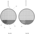
- FIG. 3 shows grids 100 in accordance with an embodiment.
- Grids used in single-particle cryo-EM e.g., Quantifoil TM , C-flat TM
- the grid 100 has a mesh of holes 110 over which the sample supporting foil is placed.
- the grid has a notch or other indented feature 120 on one edge, a solid area on one side 130, and a mark 140 and an alphanumeric code 150 patterned on the solid area that uniquely identifies each grid.
- the identifying patterns can be generated using, e.g., a laser or ink jet / dot matrix printing.
- the grid is marked by forming holes 160 through the grid.
- the identifying marks are located within the inner edge of the "clip" in Fig. 1 (G) , and so can be read optically and in the electron microscope.
- a solid area on one side of the grid facilitates gripping with forceps, tweezers, or preferably using forceps according to an embodiment with gripping surfaces matched to the flat area and to the curve of the grid, reducing risk of grid deformation. If the foil does not appreciably overlap this solid area, the risks of foil damage during grid handling will be reduced.
- Notch 120 and solid area 130 allow the grid to be oriented during a plunge into liquid cryogen and its orientation to be determined in the electron microscope.
- plunge cooling fluid flows, the thermal boundary layer thickness, and heat transfer rates vary with position on the grid, particularly along the direction of the plunge path.
- the grid orientation during plunge cooling will be fixed, so EM inspection of ice character versus position along and perpendicular to the plunge direction can be used to characterize heat transfer across the grid, to optimize grid and cooling instrument design, and to speed identification of grid regions with well vitrified sample.
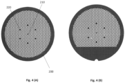
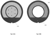
- Figure 4 (A) shows an alternative grid embodiment 200 with a hexagonal mesh of holes.
- the grid has an asymmetric mark or feature 210 located with the grid region that remains visible once clipped. This mark, a feature of some prior art grids, allows grid orientation - rotationally about a central axis perpendicular to the plane of the grid, and also which side of the grid is facing upward - to be determined using the electron microscope and optically using a magnifier or optical microscope.
- the grid has a set of solid, hole-free regions 220 one or several grid units in size , that can be laid out in an asymmetric pattern to assist visual orientation of the grid.
- Figure 4 (B) shows a similar grid with a solid gripping region and a notch.
- the flat gripping area in Fig. 3 or the smaller solid areas 220 in Fig. 4 can be patterned with a unique identifier for each grid. These can be photographed in the cooling instrument prior to cooling, verified during EM imaging, and used to track individual grids using spreadsheets or an laboratory information management system (LIMS).
- the grids could be marked individually after fabrication, so that every manufactured grid had a unique marking.
- Grid patterns that reduce thermal gradients and increase sample thermal and mechanical isolation during cooling.
- Current grids used in single particle cryo-EM have uniform thicknesses of 10 ⁇ m (Au) or 18-25 ⁇ m (Cu, Mo).
- Overall grid thickness cannot be reduced significantly without compromising mechanical rigidity during manual handling and clipping.
- the grid bar thickness and/or width can be substantially reduced in selected areas away from the "clipped" grid periphery to increase grid bar cooling rates, and reduce grid bar stiffness to allow more deformation in response to differences in contraction between the grid bar and foil during cooling. Since the grid orientation during plunge cooling can be fixed, the grid bar patterns where thickness is reduced can be arranged to form "lanes" for laminar liquid cryogen flow and maximum heat transfer rates from the sample and foil.
- Figure 5 (A) shows a standard cryo-EM grid 10 where grid bars 230 have uniform thickness and width and the grid openings have a fixed size.
- Figure 5 (B) shows a grid 240 according to an embodiment in which, in regions of the grid comprising at least 4 grid squares, the grid bars 250 have a reduced width, and where the horizontal grid bars 260, i.e., those oriented parallel to the liquid cryogen surface during a plunge, may be removed.
- the reduced width reduces grid bar heat capacity and thermal conductance in these areas. This should increase grid bar cooling rates and reduce the temperature difference between grid bars and the sample+foil during cooling with liquid cryogens.
- the areas of reduced grid bar width are preferably elongated along the direction of sample motion during plunge cooling, so as to reduce flow perturbations by grid bars and improve heat transfer.
- the areas where grid bars have reduced width and/or are removed should be placed, sized, and structured in a way as to not appreciably degrade the overall mechanical stiffness and robustness of the grid, or increase beam-induced sample motion on the foil.
- the total area of the modified grid should be less than 25% and preferably less than 10% of the total grid area, and the individual modified areas should comprise less than 5% and preferably less than 2% of the grid area.
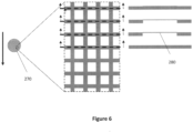
- Figure 6 shows a cryo-EM grid 270 according to an embodiment in which, in selected regions of the grid area comprising at least 4 grid squares, the grid bars 280 have a reduced thickness perpendicular to the plane of the grid.
- the reduced thickness reduces grid bar heat capacity and thermal conductance, and reduces perturbations of liquid cryogen flow and trapping of gas by grid bars during plunge cooling. This should increase grid bar cooling rates and reduce the temperature difference between grid bars and sample+foil during cooling in liquid cryogens.
- Grid areas with reduced thickness are preferably elongated along the direction of sample motion during plunge cooling.
- the areas of the grid with reduced thickness should be placed, sized, and structured in a way as to not appreciably degrade the overall mechanical stiffness and robustness of the grid when handled at its edges or in a region designed for grid gripping.
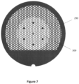
- Figure 7 shows a cryo-EM grid 290 according to an embodiment in which, in one or more regions of the grid, the grid pattern has a larger mesh size and/or narrower grid bars than in surrounding regions. Grid bars in the selected areas should cool more rapidly. Large mesh openings will increase the fraction of the sample + foil located away from the grid bars (e.g., at least 10 ⁇ m away). These regions of the sample + foil cool faster making vitrification more likely. The surrounding more mechanically robust portion of the grid will facilitate grid handling without damage.
- the grid has hexagonal patterns of apertures and grid bars, and the central region's area is approximately 25% of the grid's area.
- a circular, centrally located region of modified grid layout 300 minimizes anisotropic grid stresses that may develop during cooling.
- Cryo-EM grids are typically fabricated using electroforming, which deposits a layer of metal of uniform thickness onto a mandrel.
- a multi-thickness grid could be manufactured by performing multiple steps of photoresist deposition, patterning, and electroforming, or by bonding together two separately electroformed grids.
- Figure 8 shows a cryo-EM grid according to an embodiment that is comprised of a top grid 310, onto which the sample support foil is placed, and a bottom grid 320 having a different thickness and complementary pattern. The top and bottom are separately fabricated and then bonded together.
- the bottom grid 320 may have an aperture 330 so that the thickness of the bonded grid within the hole is just that of the top grid.
- the resulting composite grid can then have regions of very different thickness and that cool at very different rates, while maintaining mechanical rigidity.
- the two grids can be of the same material to ensure thermal contraction matching, or of different materials if, e.g., the goal is for the top grid to be under tensile stress when cold.
- Grids used in single-particle cryo-EM are typically made of Cu or Au, and are covered by foils made of amorphous carbon or Au.
- the grid is made of an electrically conducting material that has a smaller average thermal expansion coefficient between 77 K and 300 K than the foil material.
- W, Mo, Ta, and Ti grids all have small thermal expansions coefficients (4.3, 5, 6.5, and 9 ppm/°C, respectively) while Au, Cu and Ni have substantially larger expansions (14, 16, and 13 ppm/°C, respectively).
- sample + foil During cooling, the sample remains liquid to near its glass transition temperature T g ⁇ 136 K. Once it vitrifies, further cooling of sample + foil makes both want to contract, but initially they are constrained in doing so because the grid bars are warmer and have contracted less, and because grid bars are much stiffer than the sample+foil. The grid bars contract as they cool toward the final temperature, reducing the tensile stress in the foil, and this may place sample on top of the foil into compression. By minimizing thermal contraction of the grid material, and making its overall contraction from room temperature to low temperature much smaller than that of the foil, the sample + foil will remain under tension during cooling.
- the thermal contraction of the grid material between room temperature and 77 K is comparable to or smaller than the thermal contraction of the foil material between 136 K and 77 K, and is comparable to or smaller than the thermal contraction of amorphous and hexagonal ice between 136 K and 77 K.
- This is approximately true for Au foil and Ti, W or Mo grids.
- Doped Si grids contract very little - much less than any metals - and also satisfy this criterion, but are too fragile at the required thicknesses.
- foils can be fabricated from an alloy of gold and chromium.
- a Au-Cr alloy with 1% Cr has roughly 1/10 the thermal conductivity of Au but similar electrical conductivity at 77 K.
- Other alloys e.g. Au-Pt at concentrations of 1-5% Pt
- Other low thermal conductivity, high electrical conductivity alloys may be suitable.
- the liquid sample often wets through holes in the foil to the grid bars during sample deposition and/or blotting. This increases thermal mass in the vicinity of the grid bars and decreases cooling rates there.
- the fluid flow and wetting will, once the liquid solidifies, rigidly attach the foil to the grid and strongly couple their contraction during cooling, which may create stresses in the sample that cause electron beam-induced sample motion.
- the foil may be free to slide over the grid bars during cooling.
- the grid 10 has a foil 340 that has no holes where it overlaps the grid bars, and arrays of holes 360 within areas enclosed by the grid bars.
- the gap between the edge of the grid bar and the nearest hole in the foil should be at least 5% of the separation between grid bars or a few hole diameters to minimize the chance of liquid that may bulge through the holes wetting the grid bars.
- the foil may have fiducials or other marks to facilitate alignment of the foil and grid so that the solid areas of the foil line up with the grid bars.
- the hole-free regions to be registered with the grid bars may be confined only to select regions of the foil, so that the grid bars can be seen below the foil elsewhere and so facilitate alignment of the foil and grid bars.
- the foil that covers the grid can have multiple different hole sizes between 0.2 and 5 ⁇ m, distributed across its area. This diversity of hole sizes may yield a diversity of ice thicknesses and cooling rates that may facilitate obtaining optimal imaging conditions.
- the foil that covers the grid can be fabricated with regions having two or more different thicknesses, where one or more of these regions has an array of through-holes.
- the hole thickness determines the ice thickness when the sample has been properly blotted. Having two thicknesses on the same foil can increase the chance of obtaining an optimal sample thickness for imaging.
- the outer periphery of the foil can be made substantially thicker than the rest to simplify foil handling and placement on the grid.
- a foil with thickness that steps up at increasing radii could be fabricated by using disk-shaped shadow masks of increasing radius during successive depositions of metal or carbon. The innermost foil region would then be thinnest, and the outer periphery thickest.
- the shadow masks could be fabricated using standard photolithographic and etching processes from, e.g., 1 mil thick Cu foil, or from a photo-exposable polymer like SU-8 or polyimide.
- the disks for a foil array must be connected by thin lines. Shadowing by these lines can be reduced by using different line positions on successive masks, or by placing the mask in near contact and depositing the metal or carbon from an angle.
- the metal grid and metal foil can be fabricated together in a single fabrication process so that they are automatically aligned, rather than in two separate processes that requires an alignment step.
- This process could involve deposition of a release layer on a substrate; deposition of the foil layer; deposition of photoresist; exposure of the hole pattern of the foil in the photoresist; etching of the hole pattern in the foil; removal of the photoresist; deposition of a second layer of photoresist; exposure and developing of the grid pattern in the photoresist; electroforming the grid onto the foil through openings in the photoresist; removal of the photoresist; and release of the completed grid plus foil from the substrate.
- Tools for handling grids The invention further comprises designs for tools / forceps for handling cryo-EM grids without damaging them.
- Standard pointy-tipped stainless steel forceps can damage the foil if the tips impact the foil, if the grid is bent via contact with, e.g., a surface so that the foil impacts the tip, or if the tip's grip slips. Because the tips are much narrower than the grid, bumping the side of the grid into, e.g., the slot of a grid storage box bends it into a "taco" shape.
- the sample end of forceps 370 with spring action (either normally open or normally closed when not being squeezed, depending upon whether the two arms of the forceps are largely straight or cross over so that the "bottom" tip is connected to the arm that is on top at the squeezing end) has gripping elements 380 and 390 attached to each arm near their tip.
- These gripping elements are flat on their inner face in the portions that grip the grid, and their width is preferably comparable to, i.e., within ⁇ 20% of, the diameter of the grid (3.05 mm). This width will minimize the risk of the grids being bent by forces applied to their side while being held.
- the gripping elements can be structured to "mate" to the grid so that the elements only contact a certain portion of the grid, e.g., the solid region on the lower portion of the grids in Figure 3 .
- the lower gripping element 380 may have a thinned or recessed region 400 (perhaps with an aligning "nose") that matches the profile/contour of the grid. This recessed region should ideally be slightly shallower than the grid thickness, typically either 10 or 25 ⁇ m.
- the lower grid element may also have protrusions 410, with matching holes 420 in the upper gripping element 390, to help position the grid relative to the gripping elements and prevent the grid from slipping past the recessed region 400, while allowing the forceps to be closed onto and firmly grip the grid.
- the forceps body / arms may be of metals like stainless steel conventionally used in forceps, or of a polymer.
- the gripping elements may be of metal with a smooth (perhaps polished or electroplated) inner surface to minimize risk of abrasion and damage to the foil, of a polymer, or of a bendable glass or ceramic.
- the forceps gripping elements need only extend a small distance - a few millimeters - past the end of the arms of the forceps. Consequently, the gripping element can be of a thin, somewhat flexible and optically transparent polymer like polyimide, PDMS, or COC, allowing the grid's position within the gripping elements to be directly seen.
- the more rigid but opaque polymer SU-8 could also be suitable.
- These polymers can be processed into the desired shapes - and with the required micrometer-level tolerances on thickness - using standard photolithography-based microfabrication methods. Other polymers suitable for injection molding can also be used.
- the grid gripping elements may be attached using a cryogenic compatible adhesive, ultrasonically, using screws, or by other standard means to the jaws of standard spring-loaded metal or polymer forceps. Note that these forceps should preferably be usable both at room temperature and when grids are immersed in liquid ethane and liquid nitrogen.
- thermocouples in excess of 50,000 K/s and 140,000 K/s in the film and nucleate boiling regimes, respectively.
- it has dramatically simplified sample cryopreservation and storage. This performance is achieved by combining a high-speed sample translation stage, a gas management manifold that uses vacuum and warm make-up gas to remove and replace cold gas above the LN2 immediately prior to sample plunging, and a precision liquid nitrogen level control system. These components reduce the cold gas layer (where the gas temperature is below 273 K) to ⁇ 50 ⁇ m, the time for sample precooling in this cold gas to ⁇ 25 ⁇ s, and deliver the largest cooling rates ever reported using liquid nitrogen. Proof of principle experiments using Nanuq TM have demonstrated that thin buffer solution samples on cryo-EM grids can be fully vitrified using LN2 as the cooling medium.
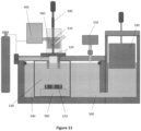
- Fig. 11 shows design for an LN2-based benchtop cryo-EM plunge cooler that eliminates manual grid handling between plunging and microscope loading, according to an embodiment.
- the small mass and impact cross-section of cryo-EM grids compared with protein crystal sample holders allows the vertical translation stage 500 to delivers speeds up to 7 m/s (and perhaps 10 m/s), which should double cooling rates compared with Nanuq TM .
- the grid holding mechanism 510 holds grids absolutely perpendicular to the LN2 surface to maximize cooling rates and minimize foil damage, and preferably automatically releases the grid into a storage container after plunge-cooling.
- the grid holding mechanism preferably has minimal hydrodynamic cross-section over a length of at least several centimeters along the plunge direction, as larger plunge speeds require substantially larger stopping distances (which makes them impractical when using liquid ethane.)
- the plunge cooler incorporates a gas management manifold 520 above the main plunge chamber, which removes cold gas present in its plunge bore via suction and replaces it with ambient temperature nitrogen gas, so as to create a transition between ambient temperature gas and liquid nitrogen over a distance of less than 100 ⁇ m, eliminating precooling of the grid in the cold gas.
- LN2 in the main sample plunge chamber 530 is cooled below its boiling point 77 K through thermal contact with a second (thermally insulated) chamber 540 in which LN2 is evaporatively cooled toward its freezing temperature of 63 K.
- This second chamber is be sealed from the atmosphere, and connects via a port to a vacuum pump 550 or other vacuum source to lower the pressure in the gas above the LN2 in the second chamber.
- the initial sample position is within a humidified chamber 560 or within a humidified gas stream.
- the humidity control system 565 preferably generates humidities up to within at least a few percent of 100% saturation to allow control over the amount of sample evaporation from the grid.
- the grids are preferably automatically deposited into a commercial electron microscope cassette or other holder 570 held within the main plunge chamber.
- a mechanical stage 580 under automated control is provided within the main chamber that accepts commercial cryo-EM microscope cassettes or custom storage boxes and automatically positions them in line with the sample plunge path defined by the vertical translation stage, so that each cold sample may be deposited into a separate compartment in each holder through a combination of vertical-only motion of the vertical translation stage and horizontal-only motion of the mechanical stage on which the sample holder storage boxes are placed.
- the LN2 level in both the main plunge chamber and the outer chamber is precisely maintained using a level control system as in the prior art Nanuq TM .
- FIG 12 shows an alternative cryo-EM sample cooler design that has been implemented in the prior art.
- the cryo-EM grid sample 600 is translated via an automated translation stage 610 from an initial position, typically within a humidified chamber (not shown), to an intermediate position. It is then cooled by one or more jets 620 of a liquid cryogen - usually liquid ethane - that exit tubes or conduits 630 (which may have a nozzle at the exit end). Once cold, the sample is quickly translated into an insulated container 630 containing liquid nitrogen, and then into a storage box or cassette 640.
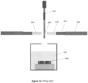
- Figure 13 shows two embodiments of the present invention that address the problem of cold gas precooling of the sample in cryogen jet coolers of the type shown in Figure 12 , by preventing it from reaching the sample.
- the cold gas 650 that emerges from the jet tube 630 ahead of the liquid cryogen 640 is prevented from reaching the sample by using a very fast shutter or blade 660.
- the shutter initially blocks the gas and cryogen flow and then abruptly moves out of the way as soon as the cold gas has cleared and a steady cryogen flow against the shutter has been established.
- the shutter can have linear or rotational motion, driven by, for example a stepper or synchronous motor, a solenoid, compressed gas, or other standard means.
- the time for the shutter to move a distance equal to the jet diameter - a few millimeters - should be comparable to or less than the sample cooling time of ⁇ 1 ms, corresponding to a speed of at least a few meters per second, in order that the whole grid be hit by the jet.
- the shutter is preferably made of a thermally insulating material such as a polymer, a glass (e.g., quartz), or a ceramic, has a small mass, and has sufficient thickness so that the sample is not precooled by conductive, convective or radiative cooling arising from a cold shutter during the short time between initiation of the liquid cryogen flow and the opening of the shutter.
- a jet or "blade" of moisture-free room temperature gas is directed across the flow from the jet tube, and has a flow velocity large enough to sweep away the cold gas but small enough that the path of the liquid cryogen (which has much more momentum) from jet tube to sample is not excessively perturbed.
- This warm gas flow can be turned on before the liquid cryogen jet is activated, and turned off once the sample is cold.
- the warm gas could be directed downward as shown, or upward, away from the insulated container in which the cold sample is to be stored.
- the gas could be dry air, N 2 , He, or any other non-flammable, non-reactive gas with a boiling temperature above the freezing temperature of the liquid cryogen.
- the gas could come from a compressed gas cylinder or other compressed gas source.
- Excess sample is removed using a combination of evaporation in a controlled humidity environment (which leads to concentration of the biomolecule in the remaining liquid) and blotting using an absorbent material, typically filter paper (e.g., as made by Whatman.) Both are imprecise and hard to control. Blotting can be performed manually by gently touching the grid using a thin strip of filter paper.
- Commercial cryo-EM cooling instruments like the Vitrobot TM from Thermo Fisher use circles of blotting paper several centimeters in diameter on pads that are pushed with controlled force and for a controlled duration at an angle against one or both sides of the grid. The angled attack of the blotting paper allows liquid to be withdrawn from one side of the grid, which helps reduce forcing of liquid through the foil holes to the backside of the foil where the grid bars make it harder to remove.
- blotting of cryo-EM grids is performed using small disks comparable to or slightly larger in diameter to a grid, of absorbent material that preferably have a pattern of surface relief.
- These disks are preferably attached to solid disk-shaped pads attached to a rod, and the rod is moved so that the disks are always parallel to the plane of the grid.
- liquid is first wicked away by the raised areas of the disk when they first make contact with the liquid meniscus.
- the disk is pressed into direct contact with the foil, liquid continues to be drawn sideways toward the raised regions of the disk that make contact.
- the disk material is soft, so as the pressure is increased the relief of its surface is reduced, further assisting in removal of excess liquid.
- the absorbent material is cut to substantially match the size and area of a cryo-EM grid. If the grid is to be blotted while held with, e.g., forceps in a plunge or jet cooler, the absorbent disk can have a cut-out so that it does not contact the forceps, and so that it can be pressed flat against the portion of the grid that is not covered by the forceps.
- the absorbent material is filter paper, which is available in many grades from suppliers such as Whatman.
- Surface relief of the filter paper can be created by embossing, which involves pressing the filter paper against a master with sufficient force that the master's pattern is transferred to the filter paper.
- Typical Whatman filter paper has a thickness of 180 ⁇ m, and this roughly limits the spatial scale on which surface relief can be patterned.
- the filter paper can be wet before embossing. It can also be shredded in, e.g., a blender with water, pressed into a master, and then dried.
- the sample support foil on the grid has a pattern of holes that is complementary to the raised regions of the absorbent disk, so that the foil is continuous where the filter paper contacts the foil and has holes elsewhere. This will further reduce the chance of liquid being pushed through holes in the foil to its backside.
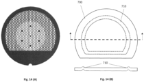
- Figure 14 (A) shows a cryo-EM grid (covered with a foil not shown) according to one aspect of the present invention, that has a solid gripping region and a central region with a larger open area fraction and smaller grid bar width.
- Figure 14 (B) shows top and cut-away side views of an absorbent disk 700, cut to avoid the gripping area of the grid. The grid is embossed to generate a raised region 710 around the outer portion of the mesh area.
Landscapes
- Chemical & Material Sciences (AREA)
- Analytical Chemistry (AREA)
- Physics & Mathematics (AREA)
- Health & Medical Sciences (AREA)
- Life Sciences & Earth Sciences (AREA)
- Biochemistry (AREA)
- General Health & Medical Sciences (AREA)
- General Physics & Mathematics (AREA)
- Immunology (AREA)
- Pathology (AREA)
- Sampling And Sample Adjustment (AREA)
Applications Claiming Priority (3)
| Application Number | Priority Date | Filing Date | Title |
|---|---|---|---|
| US201962910511P | 2019-10-04 | 2019-10-04 | |
| EP20870953.5A EP4038655B1 (de) | 2019-10-04 | 2020-10-05 | Probenträger für kryo-elektronenmikroskopie |
| PCT/US2020/054272 WO2021067940A1 (en) | 2019-10-04 | 2020-10-05 | Sample supports and sample cooling systems for cryo-electron microscopy |
Related Parent Applications (2)
| Application Number | Title | Priority Date | Filing Date |
|---|---|---|---|
| EP20870953.5A Division-Into EP4038655B1 (de) | 2019-10-04 | 2020-10-05 | Probenträger für kryo-elektronenmikroskopie |
| EP20870953.5A Division EP4038655B1 (de) | 2019-10-04 | 2020-10-05 | Probenträger für kryo-elektronenmikroskopie |
Publications (2)
| Publication Number | Publication Date |
|---|---|
| EP4407291A2 true EP4407291A2 (de) | 2024-07-31 |
| EP4407291A3 EP4407291A3 (de) | 2024-11-13 |
Family
ID=75337476
Family Applications (2)
| Application Number | Title | Priority Date | Filing Date |
|---|---|---|---|
| EP20870953.5A Active EP4038655B1 (de) | 2019-10-04 | 2020-10-05 | Probenträger für kryo-elektronenmikroskopie |
| EP24181409.4A Pending EP4407291A3 (de) | 2019-10-04 | 2020-10-05 | Probenträger und probenkühlsysteme für die kryoelektronenmikroskopie |
Family Applications Before (1)
| Application Number | Title | Priority Date | Filing Date |
|---|---|---|---|
| EP20870953.5A Active EP4038655B1 (de) | 2019-10-04 | 2020-10-05 | Probenträger für kryo-elektronenmikroskopie |
Country Status (5)
| Country | Link |
|---|---|
| US (2) | US12366509B2 (de) |
| EP (2) | EP4038655B1 (de) |
| JP (1) | JP7515579B2 (de) |
| CN (1) | CN114667586B (de) |
| WO (1) | WO2021067940A1 (de) |
Families Citing this family (13)
| Publication number | Priority date | Publication date | Assignee | Title |
|---|---|---|---|---|
| WO2020181215A1 (en) | 2019-03-06 | 2020-09-10 | Mitegen, Llc | Serial synchrotron crystallography sample holding system |
| US11925931B2 (en) | 2020-08-07 | 2024-03-12 | Mitegen, Llc | Humidified sample preparation station for serial crystallography |
| WO2022155306A1 (en) * | 2021-01-13 | 2022-07-21 | Wisconsin Alumni Research Foundation | Freezing and jacketing gas-phase biomolecules with amorphous ice for electron microscopy |
| WO2022256588A1 (en) * | 2021-06-04 | 2022-12-08 | Mitegen, Llc | Sample supports for cryo-electron microscopy |
| EP4109069A1 (de) * | 2021-06-25 | 2022-12-28 | FEI Company | Löschmaterial mit profiliertem bereich, verfahren zu dessen herstellung und dessen verwendungen |
| CN113655077B (zh) * | 2021-08-13 | 2022-11-22 | 中国科学院化学研究所 | 用于冷冻电镜的液氮自动加注及数据采集联动装置和方法 |
| US12553812B2 (en) * | 2021-09-13 | 2026-02-17 | Gregory Hirsch | Vacuum ultraviolet cryo-EM grid screening tool |
| CN113720668B (zh) * | 2021-09-22 | 2024-02-13 | 安徽理工大学 | 一种用于制作冻土动态断裂韧度试样的装置 |
| CN114002039A (zh) * | 2021-11-25 | 2022-02-01 | 丁伟 | 带有标识环的冰冻样本托 |
| US20240393215A1 (en) * | 2021-12-09 | 2024-11-28 | Mitegen, Llc | Systems, methods, and devices for achieving suitable sample thickness for single particle cryo-electron microscopy |
| US20250341450A1 (en) * | 2022-05-13 | 2025-11-06 | The Board Of Trustees Of The Leland Stanford Junior University | Cold Gas Stream Method for CryoEM Sample Grid Vitrification |
| US20250076159A1 (en) * | 2023-08-28 | 2025-03-06 | Fei Company | Liquid specimen grid for transmission electron microscope |
| EP4667900A1 (de) * | 2024-06-17 | 2025-12-24 | Fei Company | Vorrichtung zur vorbereitung von proben für ein kryoelektronenmikroskop |
Family Cites Families (44)
| Publication number | Priority date | Publication date | Assignee | Title |
|---|---|---|---|---|
| US6827979B2 (en) * | 1999-01-07 | 2004-12-07 | Northwestern University | Methods utilizing scanning probe microscope tips and products therefor or produced thereby |
| AU2004233143B2 (en) | 2003-03-20 | 2010-08-19 | Cornell Research Foundation, Inc. | Sample mounts for microcrystal crystallography |
| DE602004031073D1 (de) * | 2003-06-13 | 2011-03-03 | Fei Co | Verfahren und Vorrichtung zum Manipulieren von mikroskopischen Proben |
| US7553371B2 (en) * | 2004-02-02 | 2009-06-30 | Nanosys, Inc. | Porous substrates, articles, systems and compositions comprising nanofibers and methods of their use and production |
| EP1951437A2 (de) * | 2005-07-08 | 2008-08-06 | Wisconsin Alumni Research Foundation | Mehrschichtige polyelektrolytfilme an flüssigkeit-flüssigkeit-grenzflächen und verfahren zur bereitstellung und verwendung davon |
| JP2007139510A (ja) | 2005-11-16 | 2007-06-07 | Yamaha Motor Co Ltd | 微細構造を有する試料支持体およびその製造方法 |
| EP1987341A2 (de) | 2006-01-26 | 2008-11-05 | Cornell Research Foundation, Inc. | Mikrohergestellte werkzeuge zur bearbeitung kleiner proben |
| EP2008037A2 (de) | 2006-03-30 | 2008-12-31 | Cornell Research Foundation, Inc. | System und verfahren für erhöhte kühlraten bei der schnellkühlung kleiner biologischer proben |
| WO2008061224A1 (en) * | 2006-11-16 | 2008-05-22 | Protochips, Inc. | Sample support structure and methods |
| JP2008283892A (ja) | 2007-05-16 | 2008-11-27 | Institute Of Physical & Chemical Research | 電子顕微鏡用標識 |
| JP5058676B2 (ja) * | 2007-05-18 | 2012-10-24 | 株式会社アイエスティー | 生体標本の作製方法 |
| WO2011077949A1 (ja) * | 2009-12-22 | 2011-06-30 | 株式会社村田製作所 | 被測定物の特性を測定する方法および測定装置 |
| CN101894720B (zh) | 2010-04-14 | 2013-06-19 | 北京富纳特创新科技有限公司 | 透射电镜微栅的制备方法 |
| CN101887829B (zh) * | 2010-04-14 | 2013-03-13 | 北京富纳特创新科技有限公司 | 透射电镜微栅的制备方法 |
| CN101866804B (zh) * | 2010-04-14 | 2012-05-16 | 北京富纳特创新科技有限公司 | 透射电镜微栅 |
| US20130277573A1 (en) * | 2011-01-07 | 2013-10-24 | Dune Sciences, Inc. | Functionalized carbon membranes |
| CN102737935B (zh) | 2011-04-14 | 2015-08-26 | 清华大学 | 透射电镜微栅 |
| KR101303936B1 (ko) * | 2011-11-28 | 2013-09-05 | 한국과학기술연구원 | 가스 센서용 복합 분리막 구조체, 이를 포함하는 가스 센서 장치, 이를 이용한 가스 농도 측정 방법 및 장치 |
| WO2013148938A1 (en) | 2012-03-29 | 2013-10-03 | Mitegen, Llc | Improvements to microplates and methods for protein crystallization and biotechnology |
| US8884247B2 (en) * | 2012-09-25 | 2014-11-11 | Fei Company | System and method for ex situ analysis of a substrate |
| EP2757402B1 (de) * | 2013-01-22 | 2016-03-30 | FEI Company | Verfahren zum Betrachten von Proben mit einem Fluoreszenzmikroskop |
| EP3522199A1 (de) | 2013-08-13 | 2019-08-07 | United Kingdom Research and Innovation | Probenträger mit einer porösen metallfolier für elektronenmikroskopie |
| JP2015187974A (ja) | 2014-03-14 | 2015-10-29 | 日本電子株式会社 | 試料支持膜の製造方法 |
| CN105185679B (zh) | 2014-06-17 | 2017-04-12 | 清华大学 | 透射电镜微栅 |
| EP3169986B1 (de) | 2014-07-17 | 2020-02-26 | Scienion AG | Verfahren für die transmissionselektronenmikroskopische abbildung von probenanordnungen |
| US10309881B2 (en) * | 2015-06-30 | 2019-06-04 | The Regents Of The University Of California | Methods and apparatus for preparing aqueous specimens for electron microscopy using volatile surfactants |
| CN107960118B (zh) | 2015-07-06 | 2022-07-26 | 巴塞尔大学 | 用于高分辨率电子显微镜的无损冷冻-网格制备台 |
| US11473826B2 (en) * | 2015-07-27 | 2022-10-18 | Mitegen, Llc | Cryogenic cooling apparatus, methods, and applications |
| WO2017026348A1 (ja) * | 2015-08-07 | 2017-02-16 | 株式会社村田製作所 | 金属製多孔膜、滅菌判別方法及び洗浄判別方法 |
| EP3260839B1 (de) | 2016-06-22 | 2021-01-27 | Universiteit Maastricht | Verfahren zur vorbereitung von proben auf bildgebungs- oder diffraktionsexperimente unter kryogenen bedingungen |
| US10241015B2 (en) | 2016-07-22 | 2019-03-26 | Mitegen, Llc | Cryogenic cooling positioning apparatus, methods and applications |
| WO2018163757A1 (ja) * | 2017-03-10 | 2018-09-13 | 株式会社村田製作所 | 細胞濾過フィルタ |
| US10481222B2 (en) | 2017-07-24 | 2019-11-19 | General Electric Company | Fluid path insert for a cryogenic cooling system |
| EP3495798B1 (de) | 2017-12-08 | 2021-01-20 | FEI Company | Verbesserte herstellung von kryogenen proben z. b. zur ladungsträgerteilchenspektroskopie |
| WO2019226738A1 (en) | 2018-05-22 | 2019-11-28 | Mitegen, Llc | System for rapid cooling and warming of cells and other biological material |
| US11047796B2 (en) * | 2018-05-30 | 2021-06-29 | The Board Of Regents Of The University Of Oklahoma | Sampling tool and method for infrared spectroscopy |
| WO2020041202A1 (en) * | 2018-08-20 | 2020-02-27 | The Regents Of The University Of California | Graphene oxide affinity sample grids for cryo-em |
| US11703429B2 (en) * | 2019-02-14 | 2023-07-18 | Nanosoft, LLC | Cryogenic transmission electron microscopy sample preparation |
| US12125668B2 (en) * | 2019-02-25 | 2024-10-22 | Universiteit Antwerpen | Electron microscopy grid |
| WO2020181215A1 (en) | 2019-03-06 | 2020-09-10 | Mitegen, Llc | Serial synchrotron crystallography sample holding system |
| EP3739615A1 (de) | 2019-05-14 | 2020-11-18 | Universiteit Maastricht | Probenträger für die elektronenmikroskopie |
| US11101104B2 (en) * | 2019-08-30 | 2021-08-24 | Fei Company | Multi modal cryo compatible GUID grid |
| US11605524B2 (en) | 2019-09-27 | 2023-03-14 | Mitegen, Llc | System for sample storage and shipping for cryoelectron microscopy |
| US20250076159A1 (en) * | 2023-08-28 | 2025-03-06 | Fei Company | Liquid specimen grid for transmission electron microscope |
-
2020
- 2020-10-05 CN CN202080068057.9A patent/CN114667586B/zh active Active
- 2020-10-05 US US17/632,385 patent/US12366509B2/en active Active
- 2020-10-05 EP EP20870953.5A patent/EP4038655B1/de active Active
- 2020-10-05 WO PCT/US2020/054272 patent/WO2021067940A1/en not_active Ceased
- 2020-10-05 EP EP24181409.4A patent/EP4407291A3/de active Pending
- 2020-10-05 JP JP2022520373A patent/JP7515579B2/ja active Active
-
2025
- 2025-06-26 US US19/250,650 patent/US20250321170A1/en active Pending
Non-Patent Citations (1)
| Title |
|---|
| RUSSOPASSMORE, CURRENT OPINION IN STRUCTURAL BIOLOGY, vol. 37, 2016, pages 81 - 89 |
Also Published As
| Publication number | Publication date |
|---|---|
| US12366509B2 (en) | 2025-07-22 |
| CN114667586B (zh) | 2025-07-01 |
| JP2022550838A (ja) | 2022-12-05 |
| EP4038655B1 (de) | 2024-07-17 |
| EP4407291A3 (de) | 2024-11-13 |
| US20250321170A1 (en) | 2025-10-16 |
| US20220291098A1 (en) | 2022-09-15 |
| CN114667586A (zh) | 2022-06-24 |
| EP4038655A1 (de) | 2022-08-10 |
| JP7515579B2 (ja) | 2024-07-12 |
| WO2021067940A1 (en) | 2021-04-08 |
| EP4038655A4 (de) | 2023-11-01 |
Similar Documents
| Publication | Publication Date | Title |
|---|---|---|
| US20250321170A1 (en) | Sample supports and sample cooling systems for cryo-electron microscopy | |
| CN109690281B (zh) | 制备用于低温条件下成像或衍射实验的样本的方法和设备 | |
| US9304068B2 (en) | Cell collection apparatus, cell collecting system, and cell collecting method | |
| JP5254218B2 (ja) | 分析用顕微鏡標本を調製し保存するための装置と方法 | |
| US20100132483A1 (en) | Microfabricated tools for manipulation of small samples | |
| JP6125677B2 (ja) | 少なくとも1つの顕微鏡試料を試料キャリアから自動分離し、収集システムへ自動移送する装置および方法 | |
| EP3169986B1 (de) | Verfahren für die transmissionselektronenmikroskopische abbildung von probenanordnungen | |
| US20100229702A1 (en) | Automatic Prepared Slide Fabricating Apparatus and Automatic Prepared Slide Fabricating Method | |
| JP2022524762A (ja) | シリアルシンクロトロン結晶解析保持システム | |
| EP4095508A1 (de) | Verfahren und vorrichtung zur vorbereitung von proben unter kryogenen bedingungen für abbildungs- oder beugungsversuche in einem elektronenmikroskop | |
| US20140255978A1 (en) | Tissue dividing apparatus, tissue dividing method, and cell collecting method | |
| AU749378B2 (en) | Mechanical handling systems for laser capture microdissection | |
| US12174360B2 (en) | Imaging mechanism and sample analyzing apparatus provided with the same | |
| EP4348694B1 (de) | Probenträger für die kryoelektronenmikroskopie | |
| US20230264199A1 (en) | Paraffin-embedded block preparation device | |
| EP4556884A1 (de) | Fortschrittliche probendickenmessanordnung und verfahren zur messung einer dicke einer probe bei kryogener temperatur mittels interferometrie unter verwendung eines kryostats | |
| JP7547893B2 (ja) | 単一粒子測定装置、マニピュレーションシステム及び電極プレート | |
| Sleytr | A method for adapting the Leybold device for obtaining complementary replicas to the Balzers unit |
Legal Events
| Date | Code | Title | Description |
|---|---|---|---|
| PUAI | Public reference made under article 153(3) epc to a published international application that has entered the european phase |
Free format text: ORIGINAL CODE: 0009012 |
|
| STAA | Information on the status of an ep patent application or granted ep patent |
Free format text: STATUS: THE APPLICATION HAS BEEN PUBLISHED |
|
| AC | Divisional application: reference to earlier application |
Ref document number: 4038655 Country of ref document: EP Kind code of ref document: P |
|
| AK | Designated contracting states |
Kind code of ref document: A2 Designated state(s): AL AT BE BG CH CY CZ DE DK EE ES FI FR GB GR HR HU IE IS IT LI LT LU LV MC MK MT NL NO PL PT RO RS SE SI SK SM TR |
|
| REG | Reference to a national code |
Ref country code: DE Ref legal event code: R079 Free format text: PREVIOUS MAIN CLASS: G01N0001420000 Ipc: H01J0037200000 |
|
| PUAL | Search report despatched |
Free format text: ORIGINAL CODE: 0009013 |
|
| AK | Designated contracting states |
Kind code of ref document: A3 Designated state(s): AL AT BE BG CH CY CZ DE DK EE ES FI FR GB GR HR HU IE IS IT LI LT LU LV MC MK MT NL NO PL PT RO RS SE SI SK SM TR |
|
| RIC1 | Information provided on ipc code assigned before grant |
Ipc: G01N 35/00 20060101ALI20241004BHEP Ipc: G01N 1/40 20060101ALI20241004BHEP Ipc: H01J 37/20 20060101AFI20241004BHEP |
|
| STAA | Information on the status of an ep patent application or granted ep patent |
Free format text: STATUS: REQUEST FOR EXAMINATION WAS MADE |
|
| 17P | Request for examination filed |
Effective date: 20241210 |
|
| STAA | Information on the status of an ep patent application or granted ep patent |
Free format text: STATUS: EXAMINATION IS IN PROGRESS |
|
| 17Q | First examination report despatched |
Effective date: 20260114 |