EP4407214A1 - Steuervorrichtung für ein getriebe - Google Patents
Steuervorrichtung für ein getriebe Download PDFInfo
- Publication number
- EP4407214A1 EP4407214A1 EP22871758.3A EP22871758A EP4407214A1 EP 4407214 A1 EP4407214 A1 EP 4407214A1 EP 22871758 A EP22871758 A EP 22871758A EP 4407214 A1 EP4407214 A1 EP 4407214A1
- Authority
- EP
- European Patent Office
- Prior art keywords
- oil
- way valve
- clutch
- oil pressure
- oil port
- Prior art date
- Legal status (The legal status is an assumption and is not a legal conclusion. Google has not performed a legal analysis and makes no representation as to the accuracy of the status listed.)
- Pending
Links
Images
Classifications
-
- F—MECHANICAL ENGINEERING; LIGHTING; HEATING; WEAPONS; BLASTING
- F16—ENGINEERING ELEMENTS AND UNITS; GENERAL MEASURES FOR PRODUCING AND MAINTAINING EFFECTIVE FUNCTIONING OF MACHINES OR INSTALLATIONS; THERMAL INSULATION IN GENERAL
- F16H—GEARING
- F16H57/00—General details of gearing
- F16H57/04—Features relating to lubrication or cooling or heating
- F16H57/0434—Features relating to lubrication or cooling or heating relating to lubrication supply, e.g. pumps; Pressure control
- F16H57/0435—Pressure control for supplying lubricant; Circuits or valves therefor
-
- F—MECHANICAL ENGINEERING; LIGHTING; HEATING; WEAPONS; BLASTING
- F16—ENGINEERING ELEMENTS AND UNITS; GENERAL MEASURES FOR PRODUCING AND MAINTAINING EFFECTIVE FUNCTIONING OF MACHINES OR INSTALLATIONS; THERMAL INSULATION IN GENERAL
- F16D—COUPLINGS FOR TRANSMITTING ROTATION; CLUTCHES; BRAKES
- F16D48/00—External control of clutches
- F16D48/02—Control by fluid pressure
-
- F—MECHANICAL ENGINEERING; LIGHTING; HEATING; WEAPONS; BLASTING
- F03—MACHINES OR ENGINES FOR LIQUIDS; WIND, SPRING, OR WEIGHT MOTORS; PRODUCING MECHANICAL POWER OR A REACTIVE PROPULSIVE THRUST, NOT OTHERWISE PROVIDED FOR
- F03D—WIND MOTORS
- F03D80/00—Details, components or accessories not provided for in groups F03D1/00 - F03D17/00
- F03D80/70—Bearing or lubricating arrangements
- F03D80/705—Lubrication circuits; Lubrication delivery means
- F03D80/707—Gearing lubrication, e.g. gear boxes
-
- F—MECHANICAL ENGINEERING; LIGHTING; HEATING; WEAPONS; BLASTING
- F04—POSITIVE - DISPLACEMENT MACHINES FOR LIQUIDS; PUMPS FOR LIQUIDS OR ELASTIC FLUIDS
- F04B—POSITIVE-DISPLACEMENT MACHINES FOR LIQUIDS; PUMPS
- F04B49/00—Control, e.g. of pump delivery, or pump pressure of, or safety measures for, machines, pumps, or pumping installations, not otherwise provided for, or of interest apart from, groups F04B1/00 - F04B47/00
- F04B49/20—Control, e.g. of pump delivery, or pump pressure of, or safety measures for, machines, pumps, or pumping installations, not otherwise provided for, or of interest apart from, groups F04B1/00 - F04B47/00 by changing the driving speed
-
- F—MECHANICAL ENGINEERING; LIGHTING; HEATING; WEAPONS; BLASTING
- F04—POSITIVE - DISPLACEMENT MACHINES FOR LIQUIDS; PUMPS FOR LIQUIDS OR ELASTIC FLUIDS
- F04B—POSITIVE-DISPLACEMENT MACHINES FOR LIQUIDS; PUMPS
- F04B53/00—Component parts, details or accessories not provided for in, or of interest apart from, groups F04B1/00 - F04B23/00 or F04B39/00 - F04B47/00
- F04B53/18—Lubricating
-
- F—MECHANICAL ENGINEERING; LIGHTING; HEATING; WEAPONS; BLASTING
- F16—ENGINEERING ELEMENTS AND UNITS; GENERAL MEASURES FOR PRODUCING AND MAINTAINING EFFECTIVE FUNCTIONING OF MACHINES OR INSTALLATIONS; THERMAL INSULATION IN GENERAL
- F16D—COUPLINGS FOR TRANSMITTING ROTATION; CLUTCHES; BRAKES
- F16D48/00—External control of clutches
- F16D48/06—Control by electric or electronic means, e.g. of fluid pressure
- F16D48/066—Control of fluid pressure, e.g. using an accumulator
-
- F—MECHANICAL ENGINEERING; LIGHTING; HEATING; WEAPONS; BLASTING
- F16—ENGINEERING ELEMENTS AND UNITS; GENERAL MEASURES FOR PRODUCING AND MAINTAINING EFFECTIVE FUNCTIONING OF MACHINES OR INSTALLATIONS; THERMAL INSULATION IN GENERAL
- F16D—COUPLINGS FOR TRANSMITTING ROTATION; CLUTCHES; BRAKES
- F16D55/00—Brakes with substantially-radial braking surfaces pressed together in axial direction, e.g. disc brakes
- F16D55/02—Brakes with substantially-radial braking surfaces pressed together in axial direction, e.g. disc brakes with axially-movable discs or pads pressed against axially-located rotating members
- F16D55/22—Brakes with substantially-radial braking surfaces pressed together in axial direction, e.g. disc brakes with axially-movable discs or pads pressed against axially-located rotating members by clamping an axially-located rotating disc between movable braking members, e.g. movable brake discs or brake pads
- F16D55/224—Brakes with substantially-radial braking surfaces pressed together in axial direction, e.g. disc brakes with axially-movable discs or pads pressed against axially-located rotating members by clamping an axially-located rotating disc between movable braking members, e.g. movable brake discs or brake pads with a common actuating member for the braking members
- F16D55/225—Brakes with substantially-radial braking surfaces pressed together in axial direction, e.g. disc brakes with axially-movable discs or pads pressed against axially-located rotating members by clamping an axially-located rotating disc between movable braking members, e.g. movable brake discs or brake pads with a common actuating member for the braking members the braking members being brake pads
-
- F—MECHANICAL ENGINEERING; LIGHTING; HEATING; WEAPONS; BLASTING
- F16—ENGINEERING ELEMENTS AND UNITS; GENERAL MEASURES FOR PRODUCING AND MAINTAINING EFFECTIVE FUNCTIONING OF MACHINES OR INSTALLATIONS; THERMAL INSULATION IN GENERAL
- F16D—COUPLINGS FOR TRANSMITTING ROTATION; CLUTCHES; BRAKES
- F16D65/00—Parts or details
- F16D65/14—Actuating mechanisms for brakes; Means for initiating operation at a predetermined position
- F16D65/16—Actuating mechanisms for brakes; Means for initiating operation at a predetermined position arranged in or on the brake
- F16D65/18—Actuating mechanisms for brakes; Means for initiating operation at a predetermined position arranged in or on the brake adapted for drawing members together, e.g. for disc brakes
- F16D65/183—Actuating mechanisms for brakes; Means for initiating operation at a predetermined position arranged in or on the brake adapted for drawing members together, e.g. for disc brakes with force-transmitting members arranged side by side acting on a spot type force-applying member
-
- F—MECHANICAL ENGINEERING; LIGHTING; HEATING; WEAPONS; BLASTING
- F16—ENGINEERING ELEMENTS AND UNITS; GENERAL MEASURES FOR PRODUCING AND MAINTAINING EFFECTIVE FUNCTIONING OF MACHINES OR INSTALLATIONS; THERMAL INSULATION IN GENERAL
- F16H—GEARING
- F16H3/00—Toothed gearings for conveying rotary motion with variable gear ratio or for reversing rotary motion
- F16H3/44—Toothed gearings for conveying rotary motion with variable gear ratio or for reversing rotary motion using gears having orbital motion
- F16H3/46—Gearings having only two central gears, connected by orbital gears
- F16H3/48—Gearings having only two central gears, connected by orbital gears with single orbital gears or pairs of rigidly-connected orbital gears
- F16H3/50—Gearings having only two central gears, connected by orbital gears with single orbital gears or pairs of rigidly-connected orbital gears comprising orbital conical gears
-
- F—MECHANICAL ENGINEERING; LIGHTING; HEATING; WEAPONS; BLASTING
- F16—ENGINEERING ELEMENTS AND UNITS; GENERAL MEASURES FOR PRODUCING AND MAINTAINING EFFECTIVE FUNCTIONING OF MACHINES OR INSTALLATIONS; THERMAL INSULATION IN GENERAL
- F16H—GEARING
- F16H48/00—Differential gearings
- F16H48/06—Differential gearings with gears having orbital motion
- F16H48/08—Differential gearings with gears having orbital motion comprising bevel gears
-
- F—MECHANICAL ENGINEERING; LIGHTING; HEATING; WEAPONS; BLASTING
- F16—ENGINEERING ELEMENTS AND UNITS; GENERAL MEASURES FOR PRODUCING AND MAINTAINING EFFECTIVE FUNCTIONING OF MACHINES OR INSTALLATIONS; THERMAL INSULATION IN GENERAL
- F16H—GEARING
- F16H48/00—Differential gearings
- F16H48/20—Arrangements for suppressing or influencing the differential action, e.g. locking devices
- F16H48/22—Arrangements for suppressing or influencing the differential action, e.g. locking devices using friction clutches or brakes
-
- F—MECHANICAL ENGINEERING; LIGHTING; HEATING; WEAPONS; BLASTING
- F16—ENGINEERING ELEMENTS AND UNITS; GENERAL MEASURES FOR PRODUCING AND MAINTAINING EFFECTIVE FUNCTIONING OF MACHINES OR INSTALLATIONS; THERMAL INSULATION IN GENERAL
- F16H—GEARING
- F16H48/00—Differential gearings
- F16H48/20—Arrangements for suppressing or influencing the differential action, e.g. locking devices
- F16H48/30—Arrangements for suppressing or influencing the differential action, e.g. locking devices using externally-actuatable means
- F16H48/32—Arrangements for suppressing or influencing the differential action, e.g. locking devices using externally-actuatable means using fluid pressure actuators
-
- F—MECHANICAL ENGINEERING; LIGHTING; HEATING; WEAPONS; BLASTING
- F16—ENGINEERING ELEMENTS AND UNITS; GENERAL MEASURES FOR PRODUCING AND MAINTAINING EFFECTIVE FUNCTIONING OF MACHINES OR INSTALLATIONS; THERMAL INSULATION IN GENERAL
- F16H—GEARING
- F16H48/00—Differential gearings
- F16H48/38—Constructional details
- F16H48/40—Constructional details characterised by features of the rotating cases
-
- F—MECHANICAL ENGINEERING; LIGHTING; HEATING; WEAPONS; BLASTING
- F16—ENGINEERING ELEMENTS AND UNITS; GENERAL MEASURES FOR PRODUCING AND MAINTAINING EFFECTIVE FUNCTIONING OF MACHINES OR INSTALLATIONS; THERMAL INSULATION IN GENERAL
- F16H—GEARING
- F16H57/00—General details of gearing
- F16H57/04—Features relating to lubrication or cooling or heating
- F16H57/0434—Features relating to lubrication or cooling or heating relating to lubrication supply, e.g. pumps; Pressure control
- F16H57/0436—Pumps
- F16H57/0439—Pumps using multiple pumps with different power sources or a single pump with different power sources, e.g. one and the same pump may selectively be driven by either the engine or an electric motor
-
- F—MECHANICAL ENGINEERING; LIGHTING; HEATING; WEAPONS; BLASTING
- F16—ENGINEERING ELEMENTS AND UNITS; GENERAL MEASURES FOR PRODUCING AND MAINTAINING EFFECTIVE FUNCTIONING OF MACHINES OR INSTALLATIONS; THERMAL INSULATION IN GENERAL
- F16H—GEARING
- F16H57/00—General details of gearing
- F16H57/04—Features relating to lubrication or cooling or heating
- F16H57/0434—Features relating to lubrication or cooling or heating relating to lubrication supply, e.g. pumps; Pressure control
- F16H57/0441—Arrangements of pumps
-
- F—MECHANICAL ENGINEERING; LIGHTING; HEATING; WEAPONS; BLASTING
- F05—INDEXING SCHEMES RELATING TO ENGINES OR PUMPS IN VARIOUS SUBCLASSES OF CLASSES F01-F04
- F05B—INDEXING SCHEME RELATING TO WIND, SPRING, WEIGHT, INERTIA OR LIKE MOTORS, TO MACHINES OR ENGINES FOR LIQUIDS COVERED BY SUBCLASSES F03B, F03D AND F03G
- F05B2260/00—Function
- F05B2260/98—Lubrication
-
- F—MECHANICAL ENGINEERING; LIGHTING; HEATING; WEAPONS; BLASTING
- F16—ENGINEERING ELEMENTS AND UNITS; GENERAL MEASURES FOR PRODUCING AND MAINTAINING EFFECTIVE FUNCTIONING OF MACHINES OR INSTALLATIONS; THERMAL INSULATION IN GENERAL
- F16D—COUPLINGS FOR TRANSMITTING ROTATION; CLUTCHES; BRAKES
- F16D2500/00—External control of clutches by electric or electronic means
- F16D2500/30—Signal inputs
- F16D2500/308—Signal inputs from the transmission
- F16D2500/30802—Transmission oil properties
- F16D2500/30805—Oil pressure
-
- F—MECHANICAL ENGINEERING; LIGHTING; HEATING; WEAPONS; BLASTING
- F16—ENGINEERING ELEMENTS AND UNITS; GENERAL MEASURES FOR PRODUCING AND MAINTAINING EFFECTIVE FUNCTIONING OF MACHINES OR INSTALLATIONS; THERMAL INSULATION IN GENERAL
- F16D—COUPLINGS FOR TRANSMITTING ROTATION; CLUTCHES; BRAKES
- F16D2500/00—External control of clutches by electric or electronic means
- F16D2500/70—Details about the implementation of the control system
- F16D2500/704—Output parameters from the control unit; Target parameters to be controlled
- F16D2500/70422—Clutch parameters
- F16D2500/70424—Outputting a clutch engaged-disengaged signal
-
- F—MECHANICAL ENGINEERING; LIGHTING; HEATING; WEAPONS; BLASTING
- F16—ENGINEERING ELEMENTS AND UNITS; GENERAL MEASURES FOR PRODUCING AND MAINTAINING EFFECTIVE FUNCTIONING OF MACHINES OR INSTALLATIONS; THERMAL INSULATION IN GENERAL
- F16H—GEARING
- F16H61/00—Control functions within control units of change-speed- or reversing-gearings for conveying rotary motion ; Control of exclusively fluid gearing, friction gearing, gearings with endless flexible members or other particular types of gearing
- F16H61/02—Control functions within control units of change-speed- or reversing-gearings for conveying rotary motion ; Control of exclusively fluid gearing, friction gearing, gearings with endless flexible members or other particular types of gearing characterised by the signals used
- F16H61/0202—Control functions within control units of change-speed- or reversing-gearings for conveying rotary motion ; Control of exclusively fluid gearing, friction gearing, gearings with endless flexible members or other particular types of gearing characterised by the signals used the signals being electric
- F16H61/0204—Control functions within control units of change-speed- or reversing-gearings for conveying rotary motion ; Control of exclusively fluid gearing, friction gearing, gearings with endless flexible members or other particular types of gearing characterised by the signals used the signals being electric for gearshift control, e.g. control functions for performing shifting or generation of shift signal
- F16H61/0206—Layout of electro-hydraulic control circuits, e.g. arrangement of valves
-
- F—MECHANICAL ENGINEERING; LIGHTING; HEATING; WEAPONS; BLASTING
- F16—ENGINEERING ELEMENTS AND UNITS; GENERAL MEASURES FOR PRODUCING AND MAINTAINING EFFECTIVE FUNCTIONING OF MACHINES OR INSTALLATIONS; THERMAL INSULATION IN GENERAL
- F16H—GEARING
- F16H61/00—Control functions within control units of change-speed- or reversing-gearings for conveying rotary motion ; Control of exclusively fluid gearing, friction gearing, gearings with endless flexible members or other particular types of gearing
- F16H61/02—Control functions within control units of change-speed- or reversing-gearings for conveying rotary motion ; Control of exclusively fluid gearing, friction gearing, gearings with endless flexible members or other particular types of gearing characterised by the signals used
- F16H61/0262—Control functions within control units of change-speed- or reversing-gearings for conveying rotary motion ; Control of exclusively fluid gearing, friction gearing, gearings with endless flexible members or other particular types of gearing characterised by the signals used the signals being hydraulic
- F16H61/0265—Control functions within control units of change-speed- or reversing-gearings for conveying rotary motion ; Control of exclusively fluid gearing, friction gearing, gearings with endless flexible members or other particular types of gearing characterised by the signals used the signals being hydraulic for gearshift control, e.g. control functions for performing shifting or generation of shift signals
- F16H61/0267—Layout of hydraulic control circuits, e.g. arrangement of valves
-
- F—MECHANICAL ENGINEERING; LIGHTING; HEATING; WEAPONS; BLASTING
- F16—ENGINEERING ELEMENTS AND UNITS; GENERAL MEASURES FOR PRODUCING AND MAINTAINING EFFECTIVE FUNCTIONING OF MACHINES OR INSTALLATIONS; THERMAL INSULATION IN GENERAL
- F16N—LUBRICATING
- F16N2210/00—Applications
- F16N2210/02—Turbines
- F16N2210/025—Wind Turbines
-
- F—MECHANICAL ENGINEERING; LIGHTING; HEATING; WEAPONS; BLASTING
- F16—ENGINEERING ELEMENTS AND UNITS; GENERAL MEASURES FOR PRODUCING AND MAINTAINING EFFECTIVE FUNCTIONING OF MACHINES OR INSTALLATIONS; THERMAL INSULATION IN GENERAL
- F16N—LUBRICATING
- F16N2270/00—Controlling
-
- Y—GENERAL TAGGING OF NEW TECHNOLOGICAL DEVELOPMENTS; GENERAL TAGGING OF CROSS-SECTIONAL TECHNOLOGIES SPANNING OVER SEVERAL SECTIONS OF THE IPC; TECHNICAL SUBJECTS COVERED BY FORMER USPC CROSS-REFERENCE ART COLLECTIONS [XRACs] AND DIGESTS
- Y02—TECHNOLOGIES OR APPLICATIONS FOR MITIGATION OR ADAPTATION AGAINST CLIMATE CHANGE
- Y02E—REDUCTION OF GREENHOUSE GAS [GHG] EMISSIONS, RELATED TO ENERGY GENERATION, TRANSMISSION OR DISTRIBUTION
- Y02E10/00—Energy generation through renewable energy sources
- Y02E10/70—Wind energy
- Y02E10/72—Wind turbines with rotation axis in wind direction
Definitions
- the present invention relates to a control device, and in particular, to a control device for an oil pump of a wind turbine gearbox.
- a wind turbine gearbox is configured to transmit a torque between a main shaft, which is connected to a wind wheel, and an engine, and generally uses a planetary gear train to achieve speed increasing.
- a planetary gear train In an operation process of the gearbox, it is necessary to lubricate various components of the planetary gear train, in particular, a gear meshing portion and a bearing, to ensure normal operation of the gearbox.
- the electric pump is not activated or operates at a quite low rotation speed, so that a low flow is provided by the electric pump. Therefore, in this case, the mechanical pump is primarily responsive for circulation of lubricating oil in the gearbox for lubrication.
- a displacement of the mechanical pump is designed based on a rated load and a rated speed of the gearbox, and a flow of the mechanical pump is entirely determined by an input speed of the gearbox.
- a rotation speed of the mechanical pump is also low, which leads to insufficient oil supply. Further, insufficient oil may result in insufficient lubrication of a part such as a gear and a bearing in the gearbox, so that operation and lifetime of the gearbox may be affected.
- a control device for a gearbox which can adapt to the different lubrication requirements of the rated operating condition and the special operating condition.
- control module comprises a two-position four-way valve, the two-position four-way valve comprising an oil inlet and an oil outlet which are connected to an oil tank, a first oil port connected to the brake, and a second oil port connected to the clutch,
- the two-position four-way valve is hydraulically controlled, or controlled through an electrical signal.
- the two-position four-way valve is provided with a damping hole.
- the sensor module is further configured to detect a first oil pressure of the mechanical pump, and a second oil pressure of the electric pump, respectively; and the control module is configured to actuate, when the first oil pressure is below a first threshold, and the second oil pressure is below a second threshold, the brake caliper to clamp the brake disc and release the clutch, such that the rotation speed of the first half shaft is zero, and the rotation speed of the second half shaft is twice that of the differential housing, the control module is configured to release the brake caliper and close the clutch the first oil pressure is above the first threshold, and the second oil pressure is below the second threshold, such that the inner disc and the outer disc rotate synchronously, and the rotation speed of the first half shaft is the same as that of the second half shaft, and the control module is configured to release the brake caliper and the clutch when the second oil pressure is above the second threshold, that is, when lubrication relies on the electric pump and operation of the mechanical pump is not required, such that the rotation speed of the second half shaft is zero, and the rotation speed of
- the control module comprises a two-position four-way valve, a first two-position three-way valve, and a second two-position three-way valve, wherein the two-position four-way valve comprises an oil inlet and a first oil outlet which are connected to an oil tank, a first oil port, and a second oil port; the first two-position three-way valve comprises a second oil outlet, a third oil port connected to the first oil port, and a fourth oil port connected to the brake; the second two-position three-way valve comprises a third oil outlet, a fifth oil port connected to the second oil port, and a sixth oil port connected to the clutch;
- the two-position four-way valve, the first two-position three-way valve, and the second two-position three-way valve are each hydraulically controlled, or controlled through an electrical signal.
- the two-position four-way valve, the first two-position three-way valve, and the second two-position three-way valve are each provided with a damping hole.
- FIGS. 1 and 2 the specific implementations of the present invention will be further described below with reference to the accompanying drawings.
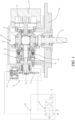
- a control device for a gearbox is suitable for a gearbox comprising a mechanical pump 30 and an electric pump (not shown). Power of the mechanical pump 30 originates from an output of the gearbox.
- a gearbox housing is denoted with 80, and an output shaft, used to drive the mechanical pump 30 to operate, of the gearbox is denoted with 81.
- the control device comprises a sensor module (not shown) configured to detect a system oil pressure of a lubricating oil of the gearbox, a differential 40, a clutch 60, a brake 50, and a control module 70.
- a sensor module configured to detect a system oil pressure of a lubricating oil of the gearbox
- a differential 40 configured to detect a system oil pressure of a lubricating oil of the gearbox
- a differential 40 configured to detect a system oil pressure of a lubricating oil of the gearbox
- a differential 40 configured to detect a system oil pressure of a lubricating oil of the gearbox
- a differential 40 configured to detect a system oil pressure of a lubricating oil of the gearbox
- a differential 40 configured to detect a system oil pressure of a lubricating oil of the gearbox
- a clutch 60 configured to detect a system oil pressure of a lubricating oil of the gearbox
- a brake 50 configured to detect a system oil pressure of a
- the differential 40 comprises an input bevel gear 44 meshing with a bevel pinion of an output shaft 81 of the gearbox, a differential housing 41 connected to the input bevel gear 44, and a first half shaft 42 and a second half shaft 43 which are provided in the differential housing 41 and mesh with a bevel pinion of the differential housing 41.
- the second half shaft 43 is connected to an input of the mechanical pump 30. According to the configuration of the differential 40, a sum of rotation speeds of the first half shaft 42 and the second half shaft 43 is twice a rotation speed of the differential housing 41.
- the brake 50 comprises a brake caliper 51, a brake disc 52, a brake disc shaft 53 fixedly connected to the brake disc 52.
- the brake disc shaft 53 is fixedly connected to the first half shaft 42, and therefore the brake disc shaft 53 and the first half shaft 42 move synchronously, or are static.
- an outer disc 61 of the clutch is connected to the differential housing 41, and an inner disc 62 of the clutch is sleeved on the first half shaft 42.
- the control module 70 is configured to actuate, when the system oil pressure is below a system oil pressure threshold, the brake caliper 51 to clamp the brake disc 52 and release the clutch 60 (in which the outer disc 61 and the inner disc 62 of the clutch are not in contact and do not rotate synchronously), such that a rotation speed of the first half shaft 42 is zero, and a rotation speed of the second half shaft 43 is twice that of the differential housing 41, and the control module is configured to release the brake caliper 51 and close the clutch when the system oil pressure is above the system oil pressure threshold, such that the inner disc and the outer disc rotate synchronously, and the rotation speed of the first half shaft 42 is the same as that of the second half shaft 43.
- the control module comprises a two-position four-way valve 71.
- the two-position four-way valve 71 comprises an oil inlet P and an oil outlet T which are connected to an oil tank, a first oil port 1 connected to the brake 50, and a second oil port 2 connected to the clutch 60.
- a valve core of the two-position four-way valve is located in a first position (a left position), such that a passage is established between the first oil port 1 and the oil inlet P, to actuate the brake caliper 51, and a passage is established between the second oil port 2 and the oil outlet T, to release the clutch.
- the first half shaft 42 is static because it is clamped by the brake caliper 51, so that the rotation speed of the first half shaft 42 is zero, the rotation speed of the second half shaft 43 connected to the mechanical pump 30 is twice that of the differential housing 41, and the mechanical pump 30 is thus at a high speed, and can provide a high volume of oil for the gearbox.
- This operating condition corresponds to a situation in which the electric pump does not operate, or operates at an extremely low rotation speed, and thus supply of the lubricating oil relies on the mechanical pump.
- the valve core of the two-position four-way valve When the system oil pressure is above the system oil pressure threshold, the valve core of the two-position four-way valve is located in a second position (a right position), such that a passage is established between the second oil port 2 and the oil inlet P to close the clutch, and a passage is established between the first oil port 1 and the oil outlet T, so that oil in the brake 50 returns to the oil tank to release the brake caliper.
- a rotation speed of the brake disc is the same as that of the first half shaft 42. Since the outer disc 61 and the inner disc 62 of the clutch rotate synchronously, the rotation speed of the first half shaft 42 is the same as that of the differential housing 41 connected to the outer disc 61 of the clutch.
- the rotation speeds of the first half shaft 42, the differential housing 41 and the second half shaft 43 are all the same.
- the rotation speed of the mechanical pump 30 is lower than that in the previous case.
- the two-position four-way valve 71 is hydraulically controlled, or controlled through an electrical signal, and is actuated according to a signal S detected by the sensor module.
- the two-position four-way valve is provided with a damping hole, to avoid an impact of the actuation of the brake and the closing of the clutch on the oil pressure.
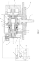
- FIG. 2 shows a control device for a gearbox according to another embodiment of the present invention.
- the control device may be configured to control three different operating conditions of the mechanical pump.
- the sensor module is further configured to detect each of a first oil pressure of the mechanical pump and a second oil pressure of the electric pump (denoted with S1 and S2, respectively), and to determine operating states of the mechanical pump and the electric pump based on the detection of the first oil pressure and the second oil pressure.
- the control module is configured to actuate, when the first oil pressure is below a first threshold, and the second oil pressure is below a second threshold (the electric pump is basically not operating), the brake caliper 51 to clamp the brake disc 52 and release the clutch 60, such that the rotation speed of the first half shaft 42 is zero, and the rotation speed of the second half shaft 43 is twice that of the differential housing 41, the control module is configured to release the brake caliper 51 and close the clutch 60 the first oil pressure is above the first threshold, and the second oil pressure is below the second threshold, such that the inner disc 62 and the outer disc 61 rotate synchronously, and the rotation speed of the first half shaft 42 is the same as that of the second half shaft 43, and the control module is configured to release the brake caliper 51 and the clutch 60 when the second oil pressure is above the second threshold, such that the rotation speed of the second half shaft is zero, and the rotation speed of the first half shaft is twice that of the differential housing, with the mechanical pump not operating.
- the control module 70 comprises a two-position four-way valve 71, a first two-position three-way valve 72, and a second two-position three-way valve 73.
- the two-position four-way valve 71 comprises an oil inlet P and a first oil outlet T which are connected to an oil tank, a first oil port 1, and a second oil port 2;
- the first two-position three-way valve 72 comprises a second oil outlet, a third oil port 3 connected to the first oil port 1, and a fourth oil port 4 connected to the brake 50;
- the second two-position three-way valve 73 comprises a third oil outlet, a fifth oil port 5 connected to the second oil port 2, and a sixth oil port 6 connected to the clutch 60.
- valve cores of the two-position four-way valve 71, the first two-position three-way valve 72, and the second two-position three-way valve 73 are each located in a first position (a left position), such that passages are established between the first oil port 1 and the oil inlet P, and between the third oil port 3 and the fourth oil port 4, respectively, to actuate the brake caliper 51, and passages are established between the fifth oil port 5 and the sixth oil port 6, and between the second oil port 2 and the first oil outlet T, respectively, to release the clutch 60.
- the rotation speed of the first half shaft 42 is zero
- the rotation speed of the second half shaft 43 (and the mechanical pump 30) is twice that of the differential housing 41
- the mechanical pump is operating at a high speed, which corresponds to an operating condition in which the electric pump is basically not operating.
- the valve core of the two-position four-way valve 71 is located in a second position (a right position), and the valve cores of the first two-position three-way valve 72 and the second two-position three-way valve 73 are each located in the first position (the left position), such that passages are established between the second oil port 2 and the oil inlet P, and between the fifth oil port 5 and the sixth oil port 6, respectively, to close the clutch 60, and passages are established between the first oil port 1 and the first oil outlet, and between the third oil port 3 and the fourth oil port 4, respectively, to release the brake caliper 51.
- the rotation speeds of the first half shaft 42, the second half shaft 43, and the differential housing 41 are all the same, so that the mechanical pump can adapt to requirements of the rated operating condition when operating at a low speed.
- the electric pump operates normally, circulation of the lubricating oil may be done by the electric pump, and the mechanical pump is used as a backup in the event of a power outage. That is, when the electric pump operates normally, the mechanical pump is not required to operate, and is in a standby operating condition with the rotation speed of zero.
- the valve cores of the first two-position three-way valve 72 and the second two-position three-way valve 73 are each located in the second position (the right position), such that a passage is established between the fourth oil port 4 and the second oil outlet to release the brake caliper 51, and a passage is established between the sixth oil port 6 and the third oil outlet to release the clutch 60.
- the two-position four-way valve, the first two-position three-way valve, and the second two-position three-way valve are each hydraulically controlled, or controlled through an electrical signal.
- the two-position four-way valve, the first two-position three-way valve, and the second two-position three-way valve are each provided with a damping hole.
- Combination of the differential, the clutch and the brake enables the mechanical pump to obtain different rotation speeds under different operating conditions, to adapt to the requirements of a current operating condition.
Landscapes
- Engineering & Computer Science (AREA)
- General Engineering & Computer Science (AREA)
- Mechanical Engineering (AREA)
- Fluid Mechanics (AREA)
- Physics & Mathematics (AREA)
- Chemical & Material Sciences (AREA)
- Analytical Chemistry (AREA)
- Sustainable Energy (AREA)
- Combustion & Propulsion (AREA)
- Sustainable Development (AREA)
- Life Sciences & Earth Sciences (AREA)
- Braking Arrangements (AREA)
- Retarders (AREA)
- General Details Of Gearings (AREA)
Applications Claiming Priority (2)
| Application Number | Priority Date | Filing Date | Title |
|---|---|---|---|
| CN202111116494.6A CN115854008A (zh) | 2021-09-23 | 2021-09-23 | 齿轮箱的控制装置 |
| PCT/CN2022/115432 WO2023045706A1 (zh) | 2021-09-23 | 2022-08-29 | 齿轮箱的控制装置 |
Publications (2)
| Publication Number | Publication Date |
|---|---|
| EP4407214A1 true EP4407214A1 (de) | 2024-07-31 |
| EP4407214A4 EP4407214A4 (de) | 2026-02-11 |
Family
ID=85652316
Family Applications (1)
| Application Number | Title | Priority Date | Filing Date |
|---|---|---|---|
| EP22871758.3A Pending EP4407214A4 (de) | 2021-09-23 | 2022-08-29 | Steuervorrichtung für ein getriebe |
Country Status (4)
| Country | Link |
|---|---|
| US (1) | US12104689B2 (de) |
| EP (1) | EP4407214A4 (de) |
| CN (1) | CN115854008A (de) |
| WO (1) | WO2023045706A1 (de) |
Families Citing this family (1)
| Publication number | Priority date | Publication date | Assignee | Title |
|---|---|---|---|---|
| CN115854009A (zh) * | 2021-09-23 | 2023-03-28 | 采埃孚(天津)风电有限公司 | 齿轮箱的控制装置 |
Family Cites Families (11)
| Publication number | Priority date | Publication date | Assignee | Title |
|---|---|---|---|---|
| US1625564A (en) * | 1926-04-15 | 1927-04-19 | Gurdon T Pollard | Transmission gear |
| JPS5982512A (ja) * | 1982-11-02 | 1984-05-12 | Toyota Motor Corp | 内燃機関の潤滑油圧制御方法及び装置 |
| JP2003139230A (ja) | 2001-10-31 | 2003-05-14 | Toyota Motor Corp | オイルポンプの制御装置 |
| US20100056315A1 (en) * | 2008-08-27 | 2010-03-04 | Scholte-Wassink Hartmut | Fluidic system, a drive train for a wind turbine and a method for actuating a mechanical component |
| KR100999715B1 (ko) * | 2008-09-01 | 2010-12-08 | 두산중공업 주식회사 | 풍력 발전 증속기용 냉각 윤활 시스템 |
| DE102011010771A1 (de) * | 2010-02-10 | 2011-08-11 | Robert Bosch GmbH, 70469 | Ölstandüberwachungseinrichtung eines Getriebes insbesondere einer Windkraftanlage |
| US20120241258A1 (en) * | 2011-03-23 | 2012-09-27 | Pradip Radhakrishnan Subramaniam | Lubricant supply system and method for controlling gearbox lubrication |
| CN202381670U (zh) * | 2011-12-20 | 2012-08-15 | 北京南口轨道交通机械有限责任公司 | 风电机组齿轮箱润滑冷却系统 |
| CN111350660B (zh) | 2020-03-12 | 2021-07-09 | 天津大学 | 机油泵控制系统 |
| CN212615359U (zh) | 2020-07-20 | 2021-02-26 | 合肥工业大学 | 一种可调速式齿轮箱润滑用齿轮泵动力装置 |
| CN215980760U (zh) | 2021-09-23 | 2022-03-08 | 采埃孚(天津)风电有限公司 | 齿轮箱的控制装置 |
-
2021
- 2021-09-23 CN CN202111116494.6A patent/CN115854008A/zh active Pending
-
2022
- 2022-08-29 WO PCT/CN2022/115432 patent/WO2023045706A1/zh not_active Ceased
- 2022-08-29 EP EP22871758.3A patent/EP4407214A4/de active Pending
- 2022-08-29 US US18/693,536 patent/US12104689B2/en active Active
Also Published As
| Publication number | Publication date |
|---|---|
| WO2023045706A1 (zh) | 2023-03-30 |
| US12104689B2 (en) | 2024-10-01 |
| US20240263696A1 (en) | 2024-08-08 |
| CN115854008A (zh) | 2023-03-28 |
| EP4407214A4 (de) | 2026-02-11 |
Similar Documents
| Publication | Publication Date | Title |
|---|---|---|
| EP3022420B1 (de) | Schmierung von achslagern während deren rechts- und linksdrehung | |
| EP3612754B1 (de) | Hydraulisches system für ein fahrzeug und fahrzeuggetriebe | |
| CN102086934A (zh) | 具有独立受控定子冷却流的变速器液压控制系统 | |
| EP4407214A1 (de) | Steuervorrichtung für ein getriebe | |
| WO2018192989A1 (en) | A hydraulic system for a vehicle, a vehicle transmission, and method for operating a vehicle transmission | |
| CN107020936A (zh) | 一种电动汽车动力总成及其应用 | |
| CN215980760U (zh) | 齿轮箱的控制装置 | |
| CN220566544U (zh) | 一种变速齿轮机构用自供油润滑保护系统 | |
| CN215596379U (zh) | 齿轮箱的控制装置 | |
| WO2024093943A1 (zh) | 变速器液压系统及其控制方法、混合动力车辆 | |
| CN209781124U (zh) | 一种可防爆自保护的摆线液压马达 | |
| US20250084831A1 (en) | Control device for gearbox | |
| CN222277472U (zh) | 一种压力可控的混动变速箱液压控制系统 | |
| CN103557253B (zh) | 双涡轮变矩器行星式变速箱用二轴摩擦片式制动离合器 | |
| CN222277473U (zh) | 一种可降低压力尖峰的混合动力变速箱液压系统 | |
| JPH01502351A (ja) | 自動車の自動変速機 | |
| CN220505460U (zh) | 一种控制阀组及液压转盘液压系统 | |
| CN217421408U (zh) | 一种回转机构用内曲线径向柱塞式回转马达 | |
| CN214699017U (zh) | 一种双机并车多工况齿轮箱 | |
| CN201731025U (zh) | 电控调速变矩器 | |
| CN118149074B (zh) | 一种船舶推进轴系用传动齿轮轴箱 | |
| CN220869998U (zh) | 一种具有全功率取力装置的液力变矩器 | |
| CN206329704U (zh) | 一种基于液压系统与齿轮传动系统的无级变速器 | |
| CN203570890U (zh) | 双涡轮变矩器行星式变速箱用二轴摩擦片式制动离合器 | |
| CN109268488A (zh) | 一种综合式液力变矩器控制阀 |
Legal Events
| Date | Code | Title | Description |
|---|---|---|---|
| STAA | Information on the status of an ep patent application or granted ep patent |
Free format text: STATUS: THE INTERNATIONAL PUBLICATION HAS BEEN MADE |
|
| PUAI | Public reference made under article 153(3) epc to a published international application that has entered the european phase |
Free format text: ORIGINAL CODE: 0009012 |
|
| STAA | Information on the status of an ep patent application or granted ep patent |
Free format text: STATUS: REQUEST FOR EXAMINATION WAS MADE |
|
| 17P | Request for examination filed |
Effective date: 20240222 |
|
| AK | Designated contracting states |
Kind code of ref document: A1 Designated state(s): AL AT BE BG CH CY CZ DE DK EE ES FI FR GB GR HR HU IE IS IT LI LT LU LV MC MK MT NL NO PL PT RO RS SE SI SK SM TR |
|
| DAV | Request for validation of the european patent (deleted) | ||
| DAX | Request for extension of the european patent (deleted) | ||
| A4 | Supplementary search report drawn up and despatched |
Effective date: 20260114 |
|
| RIC1 | Information provided on ipc code assigned before grant |
Ipc: F16H 57/04 20100101AFI20260108BHEP Ipc: F16D 55/225 20060101ALI20260108BHEP Ipc: F16D 65/22 20060101ALI20260108BHEP Ipc: F03D 15/00 20160101ALI20260108BHEP Ipc: F16H 3/44 20060101ALI20260108BHEP Ipc: F03D 80/70 20160101ALI20260108BHEP Ipc: F04B 49/20 20060101ALI20260108BHEP Ipc: F04B 53/18 20060101ALI20260108BHEP Ipc: F16D 48/02 20060101ALI20260108BHEP Ipc: F16D 48/06 20060101ALI20260108BHEP Ipc: F16D 65/18 20060101ALI20260108BHEP Ipc: F16H 3/50 20060101ALI20260108BHEP Ipc: F16H 61/02 20060101ALN20260108BHEP |