EP4406931A1 - Verfahren zur herstellung von olefinen - Google Patents
Verfahren zur herstellung von olefinen Download PDFInfo
- Publication number
- EP4406931A1 EP4406931A1 EP22872707.9A EP22872707A EP4406931A1 EP 4406931 A1 EP4406931 A1 EP 4406931A1 EP 22872707 A EP22872707 A EP 22872707A EP 4406931 A1 EP4406931 A1 EP 4406931A1
- Authority
- EP
- European Patent Office
- Prior art keywords
- olefin
- cracking
- gas
- cracked gas
- plastic
- Prior art date
- Legal status (The legal status is an assumption and is not a legal conclusion. Google has not performed a legal analysis and makes no representation as to the accuracy of the status listed.)
- Pending
Links
Images

Classifications
-
- C—CHEMISTRY; METALLURGY
- C08—ORGANIC MACROMOLECULAR COMPOUNDS; THEIR PREPARATION OR CHEMICAL WORKING-UP; COMPOSITIONS BASED THEREON
- C08J—WORKING-UP; GENERAL PROCESSES OF COMPOUNDING; AFTER-TREATMENT NOT COVERED BY SUBCLASSES C08B, C08C, C08F, C08G or C08H
- C08J11/00—Recovery or working-up of waste materials
- C08J11/04—Recovery or working-up of waste materials of polymers
- C08J11/10—Recovery or working-up of waste materials of polymers by chemically breaking down the molecular chains of polymers or breaking of crosslinks, e.g. devulcanisation
- C08J11/12—Recovery or working-up of waste materials of polymers by chemically breaking down the molecular chains of polymers or breaking of crosslinks, e.g. devulcanisation by dry-heat treatment only
-
- C—CHEMISTRY; METALLURGY
- C07—ORGANIC CHEMISTRY
- C07C—ACYCLIC OR CARBOCYCLIC COMPOUNDS
- C07C4/00—Preparation of hydrocarbons from hydrocarbons containing a larger number of carbon atoms
- C07C4/02—Preparation of hydrocarbons from hydrocarbons containing a larger number of carbon atoms by cracking a single hydrocarbon or a mixture of individually defined hydrocarbons or a normally gaseous hydrocarbon fraction
- C07C4/06—Catalytic processes
-
- C—CHEMISTRY; METALLURGY
- C07—ORGANIC CHEMISTRY
- C07C—ACYCLIC OR CARBOCYCLIC COMPOUNDS
- C07C11/00—Aliphatic unsaturated hydrocarbons
- C07C11/02—Alkenes
- C07C11/04—Ethene
-
- C—CHEMISTRY; METALLURGY
- C07—ORGANIC CHEMISTRY
- C07C—ACYCLIC OR CARBOCYCLIC COMPOUNDS
- C07C11/00—Aliphatic unsaturated hydrocarbons
- C07C11/02—Alkenes
- C07C11/06—Propene
-
- C—CHEMISTRY; METALLURGY
- C07—ORGANIC CHEMISTRY
- C07C—ACYCLIC OR CARBOCYCLIC COMPOUNDS
- C07C11/00—Aliphatic unsaturated hydrocarbons
- C07C11/02—Alkenes
- C07C11/08—Alkenes with four carbon atoms
-
- C—CHEMISTRY; METALLURGY
- C07—ORGANIC CHEMISTRY
- C07C—ACYCLIC OR CARBOCYCLIC COMPOUNDS
- C07C4/00—Preparation of hydrocarbons from hydrocarbons containing a larger number of carbon atoms
- C07C4/02—Preparation of hydrocarbons from hydrocarbons containing a larger number of carbon atoms by cracking a single hydrocarbon or a mixture of individually defined hydrocarbons or a normally gaseous hydrocarbon fraction
- C07C4/04—Thermal processes
-
- C—CHEMISTRY; METALLURGY
- C07—ORGANIC CHEMISTRY
- C07C—ACYCLIC OR CARBOCYCLIC COMPOUNDS
- C07C4/00—Preparation of hydrocarbons from hydrocarbons containing a larger number of carbon atoms
- C07C4/22—Preparation of hydrocarbons from hydrocarbons containing a larger number of carbon atoms by depolymerisation to the original monomer, e.g. dicyclopentadiene to cyclopentadiene
-
- C—CHEMISTRY; METALLURGY
- C07—ORGANIC CHEMISTRY
- C07C—ACYCLIC OR CARBOCYCLIC COMPOUNDS
- C07C7/00—Purification; Separation; Use of additives
-
- C—CHEMISTRY; METALLURGY
- C10—PETROLEUM, GAS OR COKE INDUSTRIES; TECHNICAL GASES CONTAINING CARBON MONOXIDE; FUELS; LUBRICANTS; PEAT
- C10B—DESTRUCTIVE DISTILLATION OF CARBONACEOUS MATERIALS FOR PRODUCTION OF GAS, COKE, TAR, OR SIMILAR MATERIALS
- C10B53/00—Destructive distillation, specially adapted for particular solid raw materials or solid raw materials in special form
- C10B53/07—Destructive distillation, specially adapted for particular solid raw materials or solid raw materials in special form of solid raw materials consisting of synthetic polymeric materials, e.g. tyres
-
- C—CHEMISTRY; METALLURGY
- C10—PETROLEUM, GAS OR COKE INDUSTRIES; TECHNICAL GASES CONTAINING CARBON MONOXIDE; FUELS; LUBRICANTS; PEAT
- C10G—CRACKING HYDROCARBON OILS; PRODUCTION OF LIQUID HYDROCARBON MIXTURES, e.g. BY DESTRUCTIVE HYDROGENATION, OLIGOMERISATION, POLYMERISATION; RECOVERY OF HYDROCARBON OILS FROM OIL-SHALE, OIL-SAND, OR GASES; REFINING MIXTURES MAINLY CONSISTING OF HYDROCARBONS; REFORMING OF NAPHTHA; MINERAL WAXES
- C10G1/00—Production of liquid hydrocarbon mixtures from oil-shale, oil-sand, or non-melting solid carbonaceous or similar materials, e.g. wood, coal
- C10G1/002—Production of liquid hydrocarbon mixtures from oil-shale, oil-sand, or non-melting solid carbonaceous or similar materials, e.g. wood, coal in combination with oil conversion- or refining processes
-
- C—CHEMISTRY; METALLURGY
- C10—PETROLEUM, GAS OR COKE INDUSTRIES; TECHNICAL GASES CONTAINING CARBON MONOXIDE; FUELS; LUBRICANTS; PEAT
- C10G—CRACKING HYDROCARBON OILS; PRODUCTION OF LIQUID HYDROCARBON MIXTURES, e.g. BY DESTRUCTIVE HYDROGENATION, OLIGOMERISATION, POLYMERISATION; RECOVERY OF HYDROCARBON OILS FROM OIL-SHALE, OIL-SAND, OR GASES; REFINING MIXTURES MAINLY CONSISTING OF HYDROCARBONS; REFORMING OF NAPHTHA; MINERAL WAXES
- C10G1/00—Production of liquid hydrocarbon mixtures from oil-shale, oil-sand, or non-melting solid carbonaceous or similar materials, e.g. wood, coal
- C10G1/10—Production of liquid hydrocarbon mixtures from oil-shale, oil-sand, or non-melting solid carbonaceous or similar materials, e.g. wood, coal from rubber or rubber waste
-
- C—CHEMISTRY; METALLURGY
- C10—PETROLEUM, GAS OR COKE INDUSTRIES; TECHNICAL GASES CONTAINING CARBON MONOXIDE; FUELS; LUBRICANTS; PEAT
- C10G—CRACKING HYDROCARBON OILS; PRODUCTION OF LIQUID HYDROCARBON MIXTURES, e.g. BY DESTRUCTIVE HYDROGENATION, OLIGOMERISATION, POLYMERISATION; RECOVERY OF HYDROCARBON OILS FROM OIL-SHALE, OIL-SAND, OR GASES; REFINING MIXTURES MAINLY CONSISTING OF HYDROCARBONS; REFORMING OF NAPHTHA; MINERAL WAXES
- C10G11/00—Catalytic cracking, in the absence of hydrogen, of hydrocarbon oils
- C10G11/02—Catalytic cracking, in the absence of hydrogen, of hydrocarbon oils characterised by the catalyst used
- C10G11/04—Oxides
- C10G11/05—Crystalline alumino-silicates, e.g. molecular sieves
-
- C—CHEMISTRY; METALLURGY
- C10—PETROLEUM, GAS OR COKE INDUSTRIES; TECHNICAL GASES CONTAINING CARBON MONOXIDE; FUELS; LUBRICANTS; PEAT
- C10G—CRACKING HYDROCARBON OILS; PRODUCTION OF LIQUID HYDROCARBON MIXTURES, e.g. BY DESTRUCTIVE HYDROGENATION, OLIGOMERISATION, POLYMERISATION; RECOVERY OF HYDROCARBON OILS FROM OIL-SHALE, OIL-SAND, OR GASES; REFINING MIXTURES MAINLY CONSISTING OF HYDROCARBONS; REFORMING OF NAPHTHA; MINERAL WAXES
- C10G2300/00—Aspects relating to hydrocarbon processing covered by groups C10G1/00 - C10G99/00
- C10G2300/10—Feedstock materials
- C10G2300/1003—Waste materials
-
- C—CHEMISTRY; METALLURGY
- C10—PETROLEUM, GAS OR COKE INDUSTRIES; TECHNICAL GASES CONTAINING CARBON MONOXIDE; FUELS; LUBRICANTS; PEAT
- C10G—CRACKING HYDROCARBON OILS; PRODUCTION OF LIQUID HYDROCARBON MIXTURES, e.g. BY DESTRUCTIVE HYDROGENATION, OLIGOMERISATION, POLYMERISATION; RECOVERY OF HYDROCARBON OILS FROM OIL-SHALE, OIL-SAND, OR GASES; REFINING MIXTURES MAINLY CONSISTING OF HYDROCARBONS; REFORMING OF NAPHTHA; MINERAL WAXES
- C10G2400/00—Products obtained by processes covered by groups C10G9/00 - C10G69/14
- C10G2400/20—C2-C4 olefins
-
- Y—GENERAL TAGGING OF NEW TECHNOLOGICAL DEVELOPMENTS; GENERAL TAGGING OF CROSS-SECTIONAL TECHNOLOGIES SPANNING OVER SEVERAL SECTIONS OF THE IPC; TECHNICAL SUBJECTS COVERED BY FORMER USPC CROSS-REFERENCE ART COLLECTIONS [XRACs] AND DIGESTS
- Y02—TECHNOLOGIES OR APPLICATIONS FOR MITIGATION OR ADAPTATION AGAINST CLIMATE CHANGE
- Y02P—CLIMATE CHANGE MITIGATION TECHNOLOGIES IN THE PRODUCTION OR PROCESSING OF GOODS
- Y02P20/00—Technologies relating to chemical industry
- Y02P20/141—Feedstock
- Y02P20/143—Feedstock the feedstock being recycled material, e.g. plastics
-
- Y—GENERAL TAGGING OF NEW TECHNOLOGICAL DEVELOPMENTS; GENERAL TAGGING OF CROSS-SECTIONAL TECHNOLOGIES SPANNING OVER SEVERAL SECTIONS OF THE IPC; TECHNICAL SUBJECTS COVERED BY FORMER USPC CROSS-REFERENCE ART COLLECTIONS [XRACs] AND DIGESTS
- Y02—TECHNOLOGIES OR APPLICATIONS FOR MITIGATION OR ADAPTATION AGAINST CLIMATE CHANGE
- Y02W—CLIMATE CHANGE MITIGATION TECHNOLOGIES RELATED TO WASTEWATER TREATMENT OR WASTE MANAGEMENT
- Y02W30/00—Technologies for solid waste management
- Y02W30/50—Reuse, recycling or recovery technologies
- Y02W30/62—Plastics recycling; Rubber recycling
Definitions
- the present invention relates to an olefin production method.
- Patent 1 In order to realize a carbon-cycle society, attention has been focused on technologies for chemical recycling of waste plastic, which has traditionally been thermally recycled.
- the mainstream of such technologies is a method which, as disclosed in, for example, Patent 1 or non-Patent 1, hydrogenates a cracked product obtained by cracking waste plastic and introduces the hydrogenated cracked product into a naphtha cracker to obtain an olefin.
- Patent Literature 1 Japanese Patent No. 6378368
- Non-patent Literature 1 ChemCycling @ BASF SE " Plastic Waste Pyrolysis-Challenges along the process chain", Freiberger Pyrolysetag, 18. 9. 2019, Martin Gall, Sebastian Schulze BASF SE (https://tu-kaberg.de/sites/default/files/media/institut-fuer-energievonstechnik-143/EVT/Schulungen/pyrolyse19/03._gall_schulze_basf_pyr olysetag.pdf )
- the cracked product obtained by the thermal cracking of the waste plastic is a mixture containing an olefin, paraffin, an aromatic compound, and the like.
- a hydrogenation step is required in order to increase a yield of the olefin which is a product obtained by using the naphtha cracker with the cracked product as a raw material.
- hydrogen which has a large environmental impact, is required.
- a method in accordance with an aspect of the present invention is a method for producing an olefin from plastic containing a polyolefin, the method including: a thermal cracking step of thermally cracking the plastic to obtain a thermally cracked gas; and a catalytic cracking step of cracking the thermally cracked gas in the presence of a catalyst to obtain a catalytically cracked gas, wherein R2/R1 ⁇ 1 where R 1 is a weight ratio of an olefin having 2 to 30 carbon atoms to paraffin having 1 to 30 carbon atoms in the thermally cracked gas, and R2 is a weight ratio of an olefin having 2 to 30 carbon atoms to paraffin having 1 to 30 carbon atoms in the catalytically cracked gas.
- a method in accordance with an aspect of the present invention is a method for producing an olefin from plastic containing a polyolefin, the method including: a cracking step of thermally cracking the plastic to obtain a cracked gas, wherein a temperature T4 of the cracked gas at a gas outlet of a cracking device in which the cracking step is carried out is not lower than a dew point of the cracked gas.
- a method in accordance with an aspect of the present invention is a method for producing an olefin from plastic containing a polyolefin, the method including: a cracking step of thermally cracking the plastic to obtain a cracked gas, wherein T5-T6 ⁇ 200 (°C) where T5 (°C) is a cracking temperature set in the cracking step, and T6 (°C) is a temperature of the cracked gas at a gas outlet of a cracking device in which the cracking step is carried out.
- the olefin production method in accordance with the present embodiment is a method for producing, with use of plastic such as waste plastic as a raw material, a lower olefin that can be in the carbon cycle as a plastic raw material.
- Fig. 1 is a flowchart illustrating an example of the olefin production method in accordance with the present embodiment. As illustrated in Fig. 1 , the olefin production method in accordance with the present embodiment includes a preprocessing step S12, a thermal cracking step S13, a catalytic cracking step S14, and a purification step S15. Each of these steps will be detailed later.
- FIG. 2 is a system diagram schematically illustrating a configuration of the production system 100 in accordance with Embodiment 1.
- the production system 100 in accordance with the present embodiment is a system which cracks plastic, in particular a polyolefin-based plastic, to obtain an olefin-rich gas that is rich in lower olefin gas.
- the plastic used as a raw material in the olefin production method in accordance with the present embodiment can be, for example, waste plastic.
- the plastic used as a raw material preferably is a polyolefin-based plastic such as polyethylene, polypropylene, or the like, and a content ratio of the polyolefin-based plastic is preferably not less than 80% by mass.
- the production system 100 in accordance with the present embodiment is schematically configured to include a preprocessing system 10, a thermal cracking device 21, a catalytic cracking device 22, a purification device 30, and lines L1 to L6.
- the preprocessing system 10 is supplied with plastic such as waste plastic from the line L1.
- a discharge opening of the preprocessing system 10 and a feed opening of the thermal cracking device 21 are connected to each other via the line L2.
- a material M to be supplied which has been preprocessed by the preprocessing system 10 is supplied to the thermal cracking device 21 through the line L2.
- a gas outlet 210 of the thermal cracking device 21 and a feed opening 22I of the catalytic cracking device 22 are connected to each other via the line L3.
- the material M supplied to the thermal cracking device 21 is thermally cracked and supplied to the catalytic cracking device 22 through the line L3 as a thermally cracked gas G1.
- the catalytic cracking device 22 and the purification device 30 are connected to each other via the line L4.
- the thermally cracked gas G1 supplied to the catalytic cracking device 22 is catalytically cracked and supplied to the purification device 30 as a catalytically cracked gas G2.
- the catalytically cracked gas G2 is purified by the purification device 30, and an olefin-rich gas that is rich in a lower olefin and an oil-containing liquid are discharged through the line L5 and the line L6, respectively.
- the following will discuss the devices (system) in detail.
- the preprocessing system 10 is a system which processes plastic such as waste plastic into the material M to be supplied that is suitable for being subjected to cracking. That is, the preprocessing system 10 is a system which implements the preprocessing step S12.
- the preprocessing system 10 can include a plurality of devices which carry out respective different processes.
- the preprocessing system 10 can include one or more devices selected from the group consisting of: a selection device; a crushing device; a cleaning device; a drying device; a melting device; and a dechlorinaion device.
- the selection device is a device which selects a polyolefin-based plastic from, for example, a raw material such as waste plastic.
- the selection device it is possible to use, for example, at least one selected from the group consisting of an optical selection device, a densimetric separation device, and the like.
- the crushing device is, for example, a device that crushes selected plastic.
- the cleaning device is, for example, a device that cleans crushed plastic.
- the drying device is, for example, a device that dries cleaned plastic.
- the melting device is a device that heats plastic into a liquid state.
- the dechlorinaion device is a device that removes chlorine contained in plastic.
- the thermal cracking device 21 is a device which cracks and vaporizes a substance by heating. That is, the thermal cracking device 21 is a device capable of carrying out the thermal cracking step S13 in accordance with the present embodiment.
- the thermal cracking device 21 can be, for example, an extruder, a stirred tank, a rotary kiln, a fluidized bed, or the like.
- the fluidized bed can be an internally-circulating fluidized bed or an externally-circulating fluidized bed. Further, it is possible to use a plurality of devices among these devices listed as examples, and the plurality of reactors can be connected in parallel or in series.
- a thermally cracked residue generated in the thermal cracking device 21 a hydrocarbon-containing liquid and/or hydrocarbon-containing lower paraffin gas obtained in the purification step S15
- a hydrocarbon fuel such as natural gas or kerosene.
- heat obtained by electric heating or microwave irradiation it is possible to make a combined use of at least two selected from the group consisting of: heat obtained from electric heating; heat obtained from heating by microwave irradiation; and heat obtained from the above-described burning.
- the method of heating can be direct heating or indirect heating.
- Examples of the direct heating include a method in which a microwave-absorbing substance (susceptor) is retained in the device and microwave energy is supplied to the waste plastic via the substance.
- Examples of the indirect heating include: a method in which heat of an electric heater or heat obtained by burning a hydrocarbon fuel is supplied via a heat transfer surface of the device; and a method in which water vapor or an inert gas such as nitrogen gas or CO 2 gas is heated to a high temperature by a heat source in advance and then introduced into the device. Further, it is also possible to use a method in which a solid mainly containing iron, iron oxide, alumina, silica, or the like is preheated to a high temperature by a heat source and then introduced into the device.
- the preheating of gas or solid particles by a heat source can be carried out by using a device similar to a part of an inside of the thermal cracking device 21 or to the thermal cracking device and combining the device with the thermal cracking device 21 to cause gas or a solid in these devices to circulate.
- the catalytic cracking device 22 is a device which cracks a substance by bringing a thermally cracked gas and a catalyst into contact with each other. That is, the catalytic cracking device 22 is a device which implements the catalytic cracking step S14.
- the catalytic cracking device 22 can be, for example, a fixed bed, a moving bed, or a fluidized bed. Further, a plurality of reactors selected from the group consisting of these reactors listed as examples can be used, and the plurality of reactors can be connected in parallel or in series.
- heat source necessary in the catalytic cracking step S14 it is possible to use heat obtained by burning any one or more selected from the group consisting of: coke generated in the catalytic cracking device 22 and attached to a surface of the catalyst; a hydrocarbon-containing liquid and/or hydrocarbon-containing lower paraffin gas obtained in the purification step S15; and a hydrocarbon fuel such as natural gas or kerosene.
- heat source heat obtained by electric heating or microwave irradiation.
- the method of heating can be direct heating or indirect heating.
- Examples of the direct heating include a method in which a microwave-absorbing substance (susceptor) is retained in the device and microwave energy is supplied to the waste plastic via the substance.
- Examples of the indirect heating include: a method in which heat of an electric heater or heat obtained by burning a hydrocarbon fuel is supplied via a heat transfer surface of the device; and a method in which water vapor or an inert gas such as nitrogen gas or CO 2 gas is heated to a high temperature by a heat source in advance and then introduced into the device.
- a solid mainly containing iron, iron oxide, alumina, silica, or the like is preheated to a high temperature by a heat source and then introduced into the device.
- the solid particles can be the above catalyst.
- the preheating of gas or solid particles by a heat source can be carried out by using a device similar to a part of an inside of the thermal cracking device 21 or to the thermal cracking device and combining the device with the thermal cracking device 21 to cause gas or a solid in these devices to circulate.
- the purification device 30 is a device capable of separating a mixture supplied to the purification device 30 by a known gas-liquid separation operation, a known distillation operation, or the like. That is, the purification device 30 is a device capable of carrying out the purification step S15 in accordance with the present embodiment.
- the purification device 30 can be, for example, a gas-liquid separation device or a distillation device. These devices can be used in combination, and a plurality of these devices can be connected to each other.
- the olefin production method in accordance with Embodiment 1 is carried out, for example, in accordance with the flowchart illustrated in Fig. 1 .
- the flowchart illustrated in Fig. 1 is an example and the present embodiment is not limited to this example. The following will describe steps in the olefin production method in accordance with Embodiment 1 in details.
- a raw material supplied to the preprocessing system 10 can be plastic.
- the plastic can be waste plastic included in municipal waste or the like.
- the plastic preferably mainly contains a polyolefin such as polyethylene or polypropylene, but can contain another plastic.
- the another plastic can include: a chlorinated plastic (such as chlorinated polyethylene); polyvinyl chloride (PVC); polyvinylidene chloride (PVDC); a non-chlorinated plastic (e.g.
- the waste plastic can include an unused mixed plastic or a used mixed plastic.
- the preprocessing step S12 is a step of preprocessing the plastic to obtain the material M to be supplied and subjected to the thermal cracking step S13.
- the plastic which has been subjected to the preprocessing step S12 can be supplied to the thermal cracking step S13 as the material M to be supplied that mainly contains a polyolefin-based plastic.
- the preprocessing step preferably achieves a content ratio of a polyolefin-based plastic of not less than 80% by mass.
- the thermal cracking step S13 is a step of cracking the supplied material M by heating to obtain the thermally cracked gas G1. More specifically, the thermal cracking step S13 is a step of producing the thermally cracked gas G1 by heating the olefin-based plastic contained in the supplied material M to thereby crack the olefin-based plastic into hydrocarbon with a low molecular weight having approximately 1 to 30 carbon atoms.
- a thermal cracking temperature T1 (°C) in the thermal cracking step S13 can be set in accordance with a composition of the supplied material M.
- the thermal cracking temperature T1 is preferably a high temperature at which plastic is cracked at a high cracking rate, but an excessively high temperature causes carbonization.
- the thermal cracking temperature T1 is preferably 400°C to 800°C, and more preferably 400°C to 550°C.
- a pressure in the thermal cracking step S13 is preferably low because the cracking reaction is a reaction in which the number of moles increases.
- the pressure in the thermal cracking step S13 is, for example, -80 kPa to 1000 kPa, preferably -10 kPa to 300 kPa, and more preferably 0 kPa to 100 kPa.
- water vapor or an inert gas such as nitrogen gas or CO 2 gas can coexist, and these gasses can be used as a fluidizing gas for the fluidized bed.
- reflux allows a high boiling point component to be condensed and recracked so that the number of carbon atoms can be adjusted, to some extent, so as to make it easy to handle the high boiling point component as a fuel or a raw material for a naphtha cracker.
- examples of actively employing reflux are known.
- R1 means a weight ratio of an olefin to paraffin in a thermally cracked product.
- reducing flux in thermal cracking makes it possible to increase R1.
- a raw material rich in paraffin is preferable in order to increase an olefin yield in a naphtha cracker. It is therefore preferable to reduce R1 by reflux.
- an increase in R1 causes an increase in weight ratio R2 of an olefin to paraffin in a catalytically cracked product obtained by catalytically cracking a thermally cracked product, and thus causes an increase in yield of a lower olefin.
- the inventors of the present invention found that reducing reflux is important in order to increase an olefin yield in the production method in accordance with an embodiment of the present invention.
- an increase in R1 makes it possible to obtain gas that is rich in a lower olefin. This makes it possible to produce an olefin highly efficiently without using hydrogen.
- a reflux ratio can be, for example, not more than 0.1. By reducing reflux in the thermal cracking step S13 and setting the reflux ratio to not more than 0.1, it is possible to increase R1.
- R1 is a weight ratio of an olefin having 2 to 30 carbon atoms to paraffin having 1 to 30 carbon atoms contained in the thermally cracked gas G1.
- the reflux ratio refers to a ratio of (i) to (ii): (i) a weight ratio of a condensed thermally cracked product reintroduced into the thermal cracking device 21; and (ii) a weight ratio of a thermally cracked product discharged from the thermal cracking device 21.
- the thermally cracked product refers to a cracked product derived from plastic and does not include an inert gas and the like.
- a temperature T2 (°C) of the thermally cracked gas G1 at the gas outlet 210 of the thermal cracking device 21 can be maintained so as to satisfy the following formula (1).
- the temperature T2 of the thermally cracked gas G1 at the gas outlet 210 of the thermal cracking device 21 can be maintained at not lower than a dew point of the thermally cracked gas G1.
- the dew point of the thermally cracked gas G1 refers to a temperature at which condensation starts at a thermal cracking pressure.
- the dew point varies in accordance with a composition ratio in the thermally cracked gas G1 and a pressure.
- not lower than the dew point of the thermally cracked gas G1 can mean a temperature range of not lower than 200°C, preferably not lower 300°C, and more preferably not lower 350°C.
- the above configuration makes it possible to reduce reflux in the thermal cracking step S13 and to increase R1.
- the temperature, a velocity of the thermally cracked gas G1, and the like can be actively controlled between the gas outlet 210 of the thermal cracking device 21 and the feed opening 22I of the catalytic cracking device 22.
- one or more of the following (i) to (vi) can be employed as a configuration for reducing reflux.
- R1 By thus reducing reflux in the thermal cracking step S13, it is possible to achieve R1 of not less than 1.0.
- R1 being not less than 1.0 makes it possible to obtain gas that is rich in an olefin.
- the catalytic cracking step S14 is a step capable of producing the catalytically cracked gas G2 by cracking the thermally cracked gas G1 in the presence of a catalyst into hydrocarbon with a low molecular weight having approximately 1 to 20 carbon atoms.
- a cracking temperature T3 in the catalytic cracking step S14 can be set in accordance with a composition of the thermally cracked gas G1.
- the cracking temperature T3 can be, for example, 400°C to 800°C.
- the catalyst used in the catalytic cracking step S14 can be, but are not limited to, a silicate catalyst, preferably a zeolite catalyst, and more preferably an MFI-type zeolite catalyst.
- the silicate catalyst can typically contain a silicon atom, an aluminum atom, an oxygen atom, and a hydrogen atom. Further, the silicate catalyst can contain atoms such as a sodium atom, a titanium atom, a chromium atom, a manganese atom, an iron atom, a cobalt atom, a nickel atom, a copper atom, a ruthenium atom, a rhodium atom, a palladium atom, a silver atom, an iridium atom, a platinum atom, a boron atom, a nitrogen atom, a magnesium atom, a phosphorus atom, a zinc atom, and a gallium atom.
- atoms such as a sodium atom, a titanium atom, a chromium atom, a manganese atom, an iron atom, a cobalt atom, a nickel atom, a copper atom, a ruthenium
- water vapor or an inert gas such as nitrogen gas or CO 2 gas can coexist, and these gasses can be used as a fluidizing gas for the fluidized bed.
- R2 is a weight ratio of an olefin having 2 to 30 carbon atoms to paraffin having 1 to 30 carbon atoms contained in the catalytically cracked gas G2.
- the purification step S15 is a step of separating and purifying the catalytically cracked gas G2. More specifically, the purification step S15 is a step capable of separating the catalytically cracked gas G2 into (i) a gas containing at least one hydrocarbon having a small number of carbon atoms (e.g. C 1-5 ) and (ii) a liquid containing at least one hydrocarbon having a large number of carbon atoms (e.g. not less than C 6 ). Further, the gas can be an olefin-rich gas containing not less than 90% by mass of a lower olefin. The lower olefin can contain at least one selected from the group consisting of: ethylene; propylene; and butene.
- the hydrocarbon-containing liquid obtained in the purification step S15 can be supplied to the thermal cracking device 21 or the catalytic cracking device 22. This makes it possible to further increase the olefin yield.
- the hydrocarbon-containing liquid and/or the hydrocarbon-containing lower paraffin gas obtained in the purification step S15 can be burned to be used as a heat source in any step among the preprocessing step S12 to the purification step S15. This makes it possible to reduce an environmental impact of the entire olefin production system.
- Embodiment 1 is a method for producing an olefin from plastic containing a polyolefin, the method including: the thermal cracking step S13 of preprocessing and thermal cracking the plastic to obtain the thermally cracked gas G1; and the catalytic cracking step S14 of cracking the thermally cracked gas G1 in the presence of a catalyst to obtain the catalytically cracked gas G2.
- R1 a ratio of an olefin having 2 to 30 carbon atoms to paraffin having 1 to 30 carbon atoms in the thermally cracked gas G1
- R2 a ratio of an olefin having 2 to 30 carbon atoms to paraffin having 1 to 30 carbon atoms in the catalytically cracked gas G2
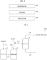
- Fig. 3 is a flowchart illustrating an example of an olefin production method in accordance with Embodiment 2. As illustrated in Fig. 3 , the olefin production method in accordance with Embodiment 2 differs from Embodiment 1 in that a cracking step S23 is not divided, unlike the thermal cracking step S13 and the catalytic cracking step S14 in accordance with Embodiment 1.
- Fig. 4 is a system diagram schematically illustrating a configuration of the olefin production system in accordance with Embodiment 2 (production system 100A).
- the production system 100A is schematically configured to include a preprocessing system 10, a cracking device 20, a purification device 30, and lines L11 to L15.
- the preprocessing system 10 is supplied with plastic such as waste plastic from the line L11.
- a discharge opening of the preprocessing system 10 and a feed opening of the cracking device 20 are connected to each other via the line L12.
- a material M to be supplied which has been preprocessed by the preprocessing system 10 is supplied to the cracking device 20 through the line L12.
- a gas outlet 20O of the catalytic cracking device 20 and the purification device 30 are connected to each other via the line L13.
- the material M supplied to the cracking device 20 is cracked and supplied to the purification device 30 as a cracked gas G3.
- the cracked gas G3 is purified by the purification device 30, and an olefin-rich gas that is rich in lower paraffin and an oil-containing liquid are discharged through the line L14 and the line L15, respectively.
- the cracking device 20 is a device which cracks and vaporizes a substance by heating.
- the cracking device 20 can be the thermal cracking device 21 or the catalytic cracking device 22 in accordance with Embodiment 1.
- the olefin production method in accordance with Embodiment 2 is carried out, for example, in accordance with the flowchart illustrated in Fig. 3 .
- the preprocessing step S22 processes respectively identical to those in the preprocessing step S12 in accordance with Embodiment 1 can be carried out. Description of the same step as in Embodiment 1 is omitted, and the cracking step S23 and the purification step S24 will be explained below.
- the cracking step S23 is a step of obtaining the cracked gas G3 by cracking the supplied material M (i) by heating alone or (ii) by heating and contacting with a catalyst.
- the cracking step S23 is a step of producing the cracked gas G3 by cracking, (i) by heating alone or (ii) by heating and contacting with a catalyst, an olefin-based plastic contained in the supplied material M into hydrocarbon with a low molecular weight having approximately 1 to 20 carbon atoms.
- the cracking device 20 in which the cracking step S23 is carried out can be the thermal cracking device 21 or the catalytic cracking device 22 described in Embodiment 1.
- the cracking device 20 can be a cracking tank in which the thermal cracking step S13 and the catalytic cracking step S14 in accordance with Embodiment 1 can be carried out in the same reaction tank. In this case, catalytic cracking can occur in the liquid phase. Further, it is possible to use the heat source described in Embodiment 1.
- water vapor or an inert gas such as nitrogen gas or CO 2 gas can coexist, and these gasses can be used as a fluidizing gas for the fluidized bed.
- a temperature T4 (°C) of the cracked gas G3 at the gas outlet 20O of the cracking device 20 is not lower than a dew point of the cracked gas G3.
- the cracking device 20 and/or a gas outlet pipe (line L13) can be heated or kept warm.
- a reflux ratio can be set to not more than 0.1. By setting the reflux ratio to not more than 0.1, it is possible to increase a weight ratio R3 of an olefin having 2 to 30 carbon atoms to paraffin having 1 to 30 carbon atoms in the cracked gas G3.
- the purification step S24 is a step of separating and purifying the cracked gas G3. More specifically, the purification step S24 is a step capable of separating the cracked gas G3 into (i) a gas containing at least one hydrocarbon having a small number of carbon atoms (e.g. C 1-5 ) and (ii) a liquid containing at least one hydrocarbon having a large number of carbon atoms (e.g. not less than C 6 ). Further, the gas can be an olefin-rich gas containing not less than 90% by mass of a lower olefin. The lower olefin can contain at least one selected from the group consisting of: ethylene; propylene; and butene.
- Embodiment 2 is a method for producing an olefin from plastic containing a polyolefin, the method including the cracking step S23 of thermal cracking the plastic to obtain the cracked gas G3, and the temperature T4 of the cracked gas G3 at the gas outlet 20O of the cracking device 20 in which the cracking step S23 is carried out is not lower than the dew point of the cracked gas G3.
- This configuration makes it possible to reduce reflux in the cracking step S23 and to increase R3 in the cracked gas G3 obtained by cracking the plastic. This makes it possible to produce an olefin highly efficiently without using hydrogen.
- the olefin production method in accordance with Embodiment 3 can be carried out, for example, in accordance with the flowchart illustrated in Fig. 3 , as in Embodiment 2.
- a temperature T6 of a cracked gas G4 at a gas outlet of a cracking device 20 in the cracking step S23 in accordance with Embodiment 3 is in a temperature range satisfying T5-T6 ⁇ 200 (°C).
- This configuration makes it possible to reduce reflux in the cracking step S23 and to increase a weight ratio O/P (R4) of an olefin having 2 to 30 carbon atoms to paraffin having 1 to 30 carbon atoms in the cracked gas G4 obtained by cracking plastic. This makes it possible to produce an olefin highly efficiently without using hydrogen.
- the present invention is not limited to the embodiments, but can be altered by a skilled person in the art within the scope of the claims.
- the present invention also encompasses, in its technical scope, any embodiment derived by combining technical means disclosed in differing embodiments.
- a reaction tube made of glass was used as the thermal cracking device.
- the reaction tube was filled with 1.0 g of polyethylene (manufactured by Sumitomo Chemical Co., Ltd., Sumikasen (registered trademark) G201G), which is a polyolefin-based plastic.
- a cold trap was connected downstream of the reaction tube, and a 2-L gas bag was connected to a downstream side of the cold trap.
- Thermal cracking of the polyethylene was carried out while nitrogen gas was caused to flow from an upstream side of the reaction tube at a rate of 10 ml/min. In so doing, an amount of an insulating material at an outlet part of the reaction tube, which outlet part was directed to the cold trap, was caused to change such that a temperature T2 at the outlet of the reaction tube (also, T6) was adjusted to 300°C, 240°C, 198°C, 310°C, and 185°C in Experimental Examples Nos. 1 to 5, respectively.
- thermally cracked products in liquid and wax states obtained were collected in the cold trap, and a thermally cracked product in a gaseous state obtained was collected in the gas bag.
- the collected thermally cracked products in liquid, wax, and gaseous states were each analyzed by gas chromatography to measure an olefin content and a paraffin content. From measured results of these contents, R1 (also, R3, R4) and a yield of an olefin having 2 to 5 carbon atoms were calculated. The calculation results are shown in Table 1.
- R2 and a yield of an olefin having 2 to 5 carbon atoms were calculated in a similar manner to R1 (also, R3, R4).
Landscapes
- Chemical & Material Sciences (AREA)
- Organic Chemistry (AREA)
- Oil, Petroleum & Natural Gas (AREA)
- Engineering & Computer Science (AREA)
- Chemical Kinetics & Catalysis (AREA)
- General Chemical & Material Sciences (AREA)
- Life Sciences & Earth Sciences (AREA)
- Wood Science & Technology (AREA)
- Physics & Mathematics (AREA)
- Thermal Sciences (AREA)
- Crystallography & Structural Chemistry (AREA)
- Water Supply & Treatment (AREA)
- Analytical Chemistry (AREA)
- Materials Engineering (AREA)
- Sustainable Development (AREA)
- Health & Medical Sciences (AREA)
- Medicinal Chemistry (AREA)
- Polymers & Plastics (AREA)
- Production Of Liquid Hydrocarbon Mixture For Refining Petroleum (AREA)
- Organic Low-Molecular-Weight Compounds And Preparation Thereof (AREA)
- Separation, Recovery Or Treatment Of Waste Materials Containing Plastics (AREA)
- Processing And Handling Of Plastics And Other Materials For Molding In General (AREA)
Priority Applications (1)
| Application Number | Priority Date | Filing Date | Title |
|---|---|---|---|
| EP24181979.6A EP4410928A3 (de) | 2021-09-24 | 2022-09-07 | Verfahren zur herstellung von olefinen |
Applications Claiming Priority (2)
| Application Number | Priority Date | Filing Date | Title |
|---|---|---|---|
| JP2021155936 | 2021-09-24 | ||
| PCT/JP2022/033505 WO2023047951A1 (ja) | 2021-09-24 | 2022-09-07 | オレフィンの製造方法 |
Related Child Applications (2)
| Application Number | Title | Priority Date | Filing Date |
|---|---|---|---|
| EP24181979.6A Division-Into EP4410928A3 (de) | 2021-09-24 | 2022-09-07 | Verfahren zur herstellung von olefinen |
| EP24181979.6A Division EP4410928A3 (de) | 2021-09-24 | 2022-09-07 | Verfahren zur herstellung von olefinen |
Publications (2)
| Publication Number | Publication Date |
|---|---|
| EP4406931A1 true EP4406931A1 (de) | 2024-07-31 |
| EP4406931A4 EP4406931A4 (de) | 2025-09-10 |
Family
ID=85720566
Family Applications (2)
| Application Number | Title | Priority Date | Filing Date |
|---|---|---|---|
| EP22872707.9A Pending EP4406931A4 (de) | 2021-09-24 | 2022-09-07 | Verfahren zur herstellung von olefinen |
| EP24181979.6A Pending EP4410928A3 (de) | 2021-09-24 | 2022-09-07 | Verfahren zur herstellung von olefinen |
Family Applications After (1)
| Application Number | Title | Priority Date | Filing Date |
|---|---|---|---|
| EP24181979.6A Pending EP4410928A3 (de) | 2021-09-24 | 2022-09-07 | Verfahren zur herstellung von olefinen |
Country Status (7)
| Country | Link |
|---|---|
| US (1) | US20240391852A1 (de) |
| EP (2) | EP4406931A4 (de) |
| JP (1) | JPWO2023047951A1 (de) |
| KR (1) | KR20240075843A (de) |
| CN (1) | CN117957276A (de) |
| TW (1) | TW202321184A (de) |
| WO (1) | WO2023047951A1 (de) |
Families Citing this family (3)
| Publication number | Priority date | Publication date | Assignee | Title |
|---|---|---|---|---|
| KR20240083186A (ko) * | 2022-12-01 | 2024-06-12 | 에스케이이노베이션 주식회사 | 폐플라스틱 열분해유의 경질 올레핀 고수율 전환 방법 및 전환 장치 |
| JP7829816B2 (ja) * | 2024-03-27 | 2026-03-13 | 住友化学株式会社 | オレフィンの製造方法 |
| JP7803503B1 (ja) * | 2024-10-29 | 2026-01-21 | 住友化学株式会社 | オレフィンの製造方法 |
Family Cites Families (6)
| Publication number | Priority date | Publication date | Assignee | Title |
|---|---|---|---|---|
| NL128466C (de) * | 1964-03-07 | |||
| JPS6378368U (de) | 1986-11-06 | 1988-05-24 | ||
| ES2673596T3 (es) | 2014-02-25 | 2018-06-25 | Saudi Basic Industries Corporation | Proceso para convertir residuo plástico mezclado (MWP) en productos petroquímicos valiosos |
| JP2016117800A (ja) * | 2014-12-19 | 2016-06-30 | 千代田化工建設株式会社 | 低級オレフィンの製造方法、低級オレフィンの製造装置および低級オレフィンの製造設備の構築方法 |
| US10669492B2 (en) * | 2017-07-18 | 2020-06-02 | Lummus Technology Llc | Integrated thermal and catalytic cracking for olefin production |
| EP4108649A4 (de) * | 2020-02-21 | 2024-03-13 | Sumitomo Chemical Company, Limited | Verfahren zur herstellung von olefinen |
-
2022
- 2022-09-07 WO PCT/JP2022/033505 patent/WO2023047951A1/ja not_active Ceased
- 2022-09-07 EP EP22872707.9A patent/EP4406931A4/de active Pending
- 2022-09-07 CN CN202280063193.8A patent/CN117957276A/zh active Pending
- 2022-09-07 EP EP24181979.6A patent/EP4410928A3/de active Pending
- 2022-09-07 US US18/694,147 patent/US20240391852A1/en active Pending
- 2022-09-07 JP JP2023549459A patent/JPWO2023047951A1/ja active Pending
- 2022-09-07 KR KR1020247011889A patent/KR20240075843A/ko active Pending
- 2022-09-16 TW TW111135190A patent/TW202321184A/zh unknown
Also Published As
| Publication number | Publication date |
|---|---|
| KR20240075843A (ko) | 2024-05-29 |
| TW202321184A (zh) | 2023-06-01 |
| US20240391852A1 (en) | 2024-11-28 |
| EP4406931A4 (de) | 2025-09-10 |
| WO2023047951A1 (ja) | 2023-03-30 |
| EP4410928A3 (de) | 2024-10-23 |
| JPWO2023047951A1 (de) | 2023-03-30 |
| EP4410928A2 (de) | 2024-08-07 |
| CN117957276A (zh) | 2024-04-30 |
Similar Documents
| Publication | Publication Date | Title |
|---|---|---|
| EP4406931A1 (de) | Verfahren zur herstellung von olefinen | |
| US20240368476A1 (en) | Light Olefin Recovery from Plastic Waste Pyrolysis | |
| Aguado et al. | Feedstock recycling of polyethylene in a two-step thermo-catalytic reaction system | |
| JP5206967B2 (ja) | 炭化水素原料からの軽質オレフィン炭化水素化合物の生産量を増加させる方法 | |
| CN102356053B (zh) | 用于制备烯烃的方法 | |
| JP4838996B2 (ja) | オレフィンの製造法 | |
| RU2543712C1 (ru) | Способ увеличения объема производства бензола и толуола | |
| Takuma et al. | Product distribution from catalytic degradation of polyethylene over H-gallosilicate | |
| JP2020508987A (ja) | 重質アルキル芳香族およびアルキル架橋非縮合アルキル芳香族化合物からの軽質アルキルモノ芳香族化合物の回収プロセス | |
| JP2007529574A (ja) | 廃材を液体燃料に転換するための方法及びプラント | |
| KR101525716B1 (ko) | 방향족 생성 증가 방법 | |
| MXPA02006800A (es) | Procesos para producir olefinas de 2 y 3 atomos de carbono a partir de hidrocarburos. | |
| JPWO2000010948A1 (ja) | エチレンおよびプロピレンの製造方法 | |
| KR20120094033A (ko) | 프로필렌 생성을 향상시키기 위한 스팀 크래커 유닛의 디보틀네킹 | |
| JP2017511831A (ja) | 統合水素化分解処理 | |
| KR101552781B1 (ko) | 방향족을 제조하는 방법 | |
| US20190359484A1 (en) | Steam reforming system and process | |
| CN100432188C (zh) | 从石脑油进料分馏和进一步裂化c6馏分生产丙烯 | |
| CN118574914A (zh) | 化学品的制造方法 | |
| WO2021071783A1 (en) | Catalytic hydrodearylation of heavy aromatic stream containing dissolved hydrogen | |
| US20150136650A1 (en) | Process for removing mercury from a coal tar product | |
| US3055956A (en) | Process for the separation of naphthalene | |
| JP7829816B2 (ja) | オレフィンの製造方法 | |
| JP7815358B1 (ja) | オレフィンの製造方法 | |
| JPS58203923A (ja) | シリカライト触媒を使用する、ある種の炭化水素の転化 |
Legal Events
| Date | Code | Title | Description |
|---|---|---|---|
| STAA | Information on the status of an ep patent application or granted ep patent |
Free format text: STATUS: THE INTERNATIONAL PUBLICATION HAS BEEN MADE |
|
| PUAI | Public reference made under article 153(3) epc to a published international application that has entered the european phase |
Free format text: ORIGINAL CODE: 0009012 |
|
| STAA | Information on the status of an ep patent application or granted ep patent |
Free format text: STATUS: REQUEST FOR EXAMINATION WAS MADE |
|
| 17P | Request for examination filed |
Effective date: 20240412 |
|
| AK | Designated contracting states |
Kind code of ref document: A1 Designated state(s): AL AT BE BG CH CY CZ DE DK EE ES FI FR GB GR HR HU IE IS IT LI LT LU LV MC MK MT NL NO PL PT RO RS SE SI SK SM TR |
|
| A4 | Supplementary search report drawn up and despatched |
Effective date: 20250807 |
|
| RIC1 | Information provided on ipc code assigned before grant |
Ipc: C07C 4/00 20060101AFI20250801BHEP Ipc: C07C 11/00 20060101ALI20250801BHEP Ipc: C08J 11/12 20060101ALI20250801BHEP Ipc: C10G 1/10 20060101ALI20250801BHEP |
|
| STAA | Information on the status of an ep patent application or granted ep patent |
Free format text: STATUS: EXAMINATION IS IN PROGRESS |