EP4406770A1 - Batterieschutzvorrichtung und -verfahren - Google Patents
Batterieschutzvorrichtung und -verfahren Download PDFInfo
- Publication number
- EP4406770A1 EP4406770A1 EP23863361.4A EP23863361A EP4406770A1 EP 4406770 A1 EP4406770 A1 EP 4406770A1 EP 23863361 A EP23863361 A EP 23863361A EP 4406770 A1 EP4406770 A1 EP 4406770A1
- Authority
- EP
- European Patent Office
- Prior art keywords
- battery cell
- charging
- time period
- battery
- discharging
- Prior art date
- Legal status (The legal status is an assumption and is not a legal conclusion. Google has not performed a legal analysis and makes no representation as to the accuracy of the status listed.)
- Granted
Links
Images


Classifications
-
- H—ELECTRICITY
- H02—GENERATION; CONVERSION OR DISTRIBUTION OF ELECTRIC POWER
- H02J—ELECTRIC POWER NETWORKS; CIRCUIT ARRANGEMENTS OR SYSTEMS FOR SUPPLYING OR DISTRIBUTING ELECTRIC POWER; SYSTEMS FOR STORING ELECTRIC ENERGY
- H02J7/00—Circuit arrangements for charging or discharging batteries or for supplying loads from batteries
- H02J7/60—Circuit arrangements for charging or discharging batteries or for supplying loads from batteries including safety or protection arrangements
- H02J7/663—Circuit arrangements for charging or discharging batteries or for supplying loads from batteries including safety or protection arrangements using battery or load disconnect circuits
-
- H—ELECTRICITY
- H01—ELECTRIC ELEMENTS
- H01M—PROCESSES OR MEANS, e.g. BATTERIES, FOR THE DIRECT CONVERSION OF CHEMICAL ENERGY INTO ELECTRICAL ENERGY
- H01M10/00—Secondary cells; Manufacture thereof
- H01M10/42—Methods or arrangements for servicing or maintenance of secondary cells or secondary half-cells
-
- B—PERFORMING OPERATIONS; TRANSPORTING
- B60—VEHICLES IN GENERAL
- B60L—PROPULSION OF ELECTRICALLY-PROPELLED VEHICLES; SUPPLYING ELECTRIC POWER FOR AUXILIARY EQUIPMENT OF ELECTRICALLY-PROPELLED VEHICLES; ELECTRODYNAMIC BRAKE SYSTEMS FOR VEHICLES IN GENERAL; MAGNETIC SUSPENSION OR LEVITATION FOR VEHICLES; MONITORING OPERATING VARIABLES OF ELECTRICALLY-PROPELLED VEHICLES; ELECTRIC SAFETY DEVICES FOR ELECTRICALLY-PROPELLED VEHICLES
- B60L3/00—Electric devices on electrically-propelled vehicles for safety purposes; Monitoring operating variables, e.g. speed, deceleration or energy consumption
- B60L3/0023—Detecting, eliminating, remedying or compensating for drive train abnormalities, e.g. failures within the drive train
- B60L3/0046—Detecting, eliminating, remedying or compensating for drive train abnormalities, e.g. failures within the drive train relating to electric energy storage systems, e.g. batteries or capacitors
-
- B—PERFORMING OPERATIONS; TRANSPORTING
- B60—VEHICLES IN GENERAL
- B60L—PROPULSION OF ELECTRICALLY-PROPELLED VEHICLES; SUPPLYING ELECTRIC POWER FOR AUXILIARY EQUIPMENT OF ELECTRICALLY-PROPELLED VEHICLES; ELECTRODYNAMIC BRAKE SYSTEMS FOR VEHICLES IN GENERAL; MAGNETIC SUSPENSION OR LEVITATION FOR VEHICLES; MONITORING OPERATING VARIABLES OF ELECTRICALLY-PROPELLED VEHICLES; ELECTRIC SAFETY DEVICES FOR ELECTRICALLY-PROPELLED VEHICLES
- B60L3/00—Electric devices on electrically-propelled vehicles for safety purposes; Monitoring operating variables, e.g. speed, deceleration or energy consumption
- B60L3/12—Recording operating variables ; Monitoring of operating variables
-
- B—PERFORMING OPERATIONS; TRANSPORTING
- B60—VEHICLES IN GENERAL
- B60L—PROPULSION OF ELECTRICALLY-PROPELLED VEHICLES; SUPPLYING ELECTRIC POWER FOR AUXILIARY EQUIPMENT OF ELECTRICALLY-PROPELLED VEHICLES; ELECTRODYNAMIC BRAKE SYSTEMS FOR VEHICLES IN GENERAL; MAGNETIC SUSPENSION OR LEVITATION FOR VEHICLES; MONITORING OPERATING VARIABLES OF ELECTRICALLY-PROPELLED VEHICLES; ELECTRIC SAFETY DEVICES FOR ELECTRICALLY-PROPELLED VEHICLES
- B60L58/00—Methods or circuit arrangements for monitoring or controlling batteries or fuel cells, specially adapted for electric vehicles
- B60L58/10—Methods or circuit arrangements for monitoring or controlling batteries or fuel cells, specially adapted for electric vehicles for monitoring or controlling batteries
- B60L58/12—Methods or circuit arrangements for monitoring or controlling batteries or fuel cells, specially adapted for electric vehicles for monitoring or controlling batteries responding to state of charge [SoC]
-
- B—PERFORMING OPERATIONS; TRANSPORTING
- B60—VEHICLES IN GENERAL
- B60L—PROPULSION OF ELECTRICALLY-PROPELLED VEHICLES; SUPPLYING ELECTRIC POWER FOR AUXILIARY EQUIPMENT OF ELECTRICALLY-PROPELLED VEHICLES; ELECTRODYNAMIC BRAKE SYSTEMS FOR VEHICLES IN GENERAL; MAGNETIC SUSPENSION OR LEVITATION FOR VEHICLES; MONITORING OPERATING VARIABLES OF ELECTRICALLY-PROPELLED VEHICLES; ELECTRIC SAFETY DEVICES FOR ELECTRICALLY-PROPELLED VEHICLES
- B60L58/00—Methods or circuit arrangements for monitoring or controlling batteries or fuel cells, specially adapted for electric vehicles
- B60L58/10—Methods or circuit arrangements for monitoring or controlling batteries or fuel cells, specially adapted for electric vehicles for monitoring or controlling batteries
- B60L58/16—Methods or circuit arrangements for monitoring or controlling batteries or fuel cells, specially adapted for electric vehicles for monitoring or controlling batteries responding to battery ageing, e.g. to the number of charging cycles or the state of health [SoH]
-
- B—PERFORMING OPERATIONS; TRANSPORTING
- B60—VEHICLES IN GENERAL
- B60L—PROPULSION OF ELECTRICALLY-PROPELLED VEHICLES; SUPPLYING ELECTRIC POWER FOR AUXILIARY EQUIPMENT OF ELECTRICALLY-PROPELLED VEHICLES; ELECTRODYNAMIC BRAKE SYSTEMS FOR VEHICLES IN GENERAL; MAGNETIC SUSPENSION OR LEVITATION FOR VEHICLES; MONITORING OPERATING VARIABLES OF ELECTRICALLY-PROPELLED VEHICLES; ELECTRIC SAFETY DEVICES FOR ELECTRICALLY-PROPELLED VEHICLES
- B60L58/00—Methods or circuit arrangements for monitoring or controlling batteries or fuel cells, specially adapted for electric vehicles
- B60L58/10—Methods or circuit arrangements for monitoring or controlling batteries or fuel cells, specially adapted for electric vehicles for monitoring or controlling batteries
- B60L58/18—Methods or circuit arrangements for monitoring or controlling batteries or fuel cells, specially adapted for electric vehicles for monitoring or controlling batteries of two or more battery modules
-
- B—PERFORMING OPERATIONS; TRANSPORTING
- B60—VEHICLES IN GENERAL
- B60L—PROPULSION OF ELECTRICALLY-PROPELLED VEHICLES; SUPPLYING ELECTRIC POWER FOR AUXILIARY EQUIPMENT OF ELECTRICALLY-PROPELLED VEHICLES; ELECTRODYNAMIC BRAKE SYSTEMS FOR VEHICLES IN GENERAL; MAGNETIC SUSPENSION OR LEVITATION FOR VEHICLES; MONITORING OPERATING VARIABLES OF ELECTRICALLY-PROPELLED VEHICLES; ELECTRIC SAFETY DEVICES FOR ELECTRICALLY-PROPELLED VEHICLES
- B60L7/00—Electrodynamic brake systems for vehicles in general
- B60L7/10—Dynamic electric regenerative braking
-
- H—ELECTRICITY
- H01—ELECTRIC ELEMENTS
- H01M—PROCESSES OR MEANS, e.g. BATTERIES, FOR THE DIRECT CONVERSION OF CHEMICAL ENERGY INTO ELECTRICAL ENERGY
- H01M10/00—Secondary cells; Manufacture thereof
- H01M10/42—Methods or arrangements for servicing or maintenance of secondary cells or secondary half-cells
- H01M10/425—Structural combination with electronic components, e.g. electronic circuits integrated to the outside of the casing
- H01M10/4257—Smart batteries, e.g. electronic circuits inside the housing of the cells or batteries
-
- H—ELECTRICITY
- H01—ELECTRIC ELEMENTS
- H01M—PROCESSES OR MEANS, e.g. BATTERIES, FOR THE DIRECT CONVERSION OF CHEMICAL ENERGY INTO ELECTRICAL ENERGY
- H01M10/00—Secondary cells; Manufacture thereof
- H01M10/42—Methods or arrangements for servicing or maintenance of secondary cells or secondary half-cells
- H01M10/44—Methods for charging or discharging
- H01M10/443—Methods for charging or discharging in response to temperature
-
- H—ELECTRICITY
- H01—ELECTRIC ELEMENTS
- H01M—PROCESSES OR MEANS, e.g. BATTERIES, FOR THE DIRECT CONVERSION OF CHEMICAL ENERGY INTO ELECTRICAL ENERGY
- H01M10/00—Secondary cells; Manufacture thereof
- H01M10/42—Methods or arrangements for servicing or maintenance of secondary cells or secondary half-cells
- H01M10/48—Accumulators combined with arrangements for measuring, testing or indicating the condition of cells, e.g. the level or density of the electrolyte
- H01M10/486—Accumulators combined with arrangements for measuring, testing or indicating the condition of cells, e.g. the level or density of the electrolyte for measuring temperature
-
- H—ELECTRICITY
- H02—GENERATION; CONVERSION OR DISTRIBUTION OF ELECTRIC POWER
- H02J—ELECTRIC POWER NETWORKS; CIRCUIT ARRANGEMENTS OR SYSTEMS FOR SUPPLYING OR DISTRIBUTING ELECTRIC POWER; SYSTEMS FOR STORING ELECTRIC ENERGY
- H02J7/00—Circuit arrangements for charging or discharging batteries or for supplying loads from batteries
- H02J7/60—Circuit arrangements for charging or discharging batteries or for supplying loads from batteries including safety or protection arrangements
- H02J7/61—Circuit arrangements for charging or discharging batteries or for supplying loads from batteries including safety or protection arrangements against overcharge
-
- H—ELECTRICITY
- H02—GENERATION; CONVERSION OR DISTRIBUTION OF ELECTRIC POWER
- H02J—ELECTRIC POWER NETWORKS; CIRCUIT ARRANGEMENTS OR SYSTEMS FOR SUPPLYING OR DISTRIBUTING ELECTRIC POWER; SYSTEMS FOR STORING ELECTRIC ENERGY
- H02J7/00—Circuit arrangements for charging or discharging batteries or for supplying loads from batteries
- H02J7/90—Regulation of charging or discharging current or voltage
- H02J7/933—Regulation of charging or discharging current or voltage the cycle being controlled or terminated in response to electric parameters
-
- H—ELECTRICITY
- H02—GENERATION; CONVERSION OR DISTRIBUTION OF ELECTRIC POWER
- H02J—ELECTRIC POWER NETWORKS; CIRCUIT ARRANGEMENTS OR SYSTEMS FOR SUPPLYING OR DISTRIBUTING ELECTRIC POWER; SYSTEMS FOR STORING ELECTRIC ENERGY
- H02J7/00—Circuit arrangements for charging or discharging batteries or for supplying loads from batteries
- H02J7/90—Regulation of charging or discharging current or voltage
- H02J7/971—Regulation of charging or discharging current or voltage the charge cycle being controlled or terminated in response to non-electric parameters
- H02J7/975—Regulation of charging or discharging current or voltage the charge cycle being controlled or terminated in response to non-electric parameters in response to temperature
- H02J7/977—Regulation of charging or discharging current or voltage the charge cycle being controlled or terminated in response to non-electric parameters in response to temperature of the battery
-
- B—PERFORMING OPERATIONS; TRANSPORTING
- B60—VEHICLES IN GENERAL
- B60L—PROPULSION OF ELECTRICALLY-PROPELLED VEHICLES; SUPPLYING ELECTRIC POWER FOR AUXILIARY EQUIPMENT OF ELECTRICALLY-PROPELLED VEHICLES; ELECTRODYNAMIC BRAKE SYSTEMS FOR VEHICLES IN GENERAL; MAGNETIC SUSPENSION OR LEVITATION FOR VEHICLES; MONITORING OPERATING VARIABLES OF ELECTRICALLY-PROPELLED VEHICLES; ELECTRIC SAFETY DEVICES FOR ELECTRICALLY-PROPELLED VEHICLES
- B60L2200/00—Type of vehicles
- B60L2200/12—Bikes
-
- B—PERFORMING OPERATIONS; TRANSPORTING
- B60—VEHICLES IN GENERAL
- B60L—PROPULSION OF ELECTRICALLY-PROPELLED VEHICLES; SUPPLYING ELECTRIC POWER FOR AUXILIARY EQUIPMENT OF ELECTRICALLY-PROPELLED VEHICLES; ELECTRODYNAMIC BRAKE SYSTEMS FOR VEHICLES IN GENERAL; MAGNETIC SUSPENSION OR LEVITATION FOR VEHICLES; MONITORING OPERATING VARIABLES OF ELECTRICALLY-PROPELLED VEHICLES; ELECTRIC SAFETY DEVICES FOR ELECTRICALLY-PROPELLED VEHICLES
- B60L2240/00—Control parameters of input or output; Target parameters
- B60L2240/40—Drive Train control parameters
- B60L2240/54—Drive Train control parameters related to batteries
- B60L2240/545—Temperature
-
- B—PERFORMING OPERATIONS; TRANSPORTING
- B60—VEHICLES IN GENERAL
- B60L—PROPULSION OF ELECTRICALLY-PROPELLED VEHICLES; SUPPLYING ELECTRIC POWER FOR AUXILIARY EQUIPMENT OF ELECTRICALLY-PROPELLED VEHICLES; ELECTRODYNAMIC BRAKE SYSTEMS FOR VEHICLES IN GENERAL; MAGNETIC SUSPENSION OR LEVITATION FOR VEHICLES; MONITORING OPERATING VARIABLES OF ELECTRICALLY-PROPELLED VEHICLES; ELECTRIC SAFETY DEVICES FOR ELECTRICALLY-PROPELLED VEHICLES
- B60L2240/00—Control parameters of input or output; Target parameters
- B60L2240/40—Drive Train control parameters
- B60L2240/54—Drive Train control parameters related to batteries
- B60L2240/549—Current
-
- B—PERFORMING OPERATIONS; TRANSPORTING
- B60—VEHICLES IN GENERAL
- B60L—PROPULSION OF ELECTRICALLY-PROPELLED VEHICLES; SUPPLYING ELECTRIC POWER FOR AUXILIARY EQUIPMENT OF ELECTRICALLY-PROPELLED VEHICLES; ELECTRODYNAMIC BRAKE SYSTEMS FOR VEHICLES IN GENERAL; MAGNETIC SUSPENSION OR LEVITATION FOR VEHICLES; MONITORING OPERATING VARIABLES OF ELECTRICALLY-PROPELLED VEHICLES; ELECTRIC SAFETY DEVICES FOR ELECTRICALLY-PROPELLED VEHICLES
- B60L2240/00—Control parameters of input or output; Target parameters
- B60L2240/80—Time limits
-
- B—PERFORMING OPERATIONS; TRANSPORTING
- B60—VEHICLES IN GENERAL
- B60Y—INDEXING SCHEME RELATING TO ASPECTS CROSS-CUTTING VEHICLE TECHNOLOGY
- B60Y2200/00—Type of vehicle
- B60Y2200/10—Road Vehicles
- B60Y2200/13—Bicycles; Tricycles
-
- B—PERFORMING OPERATIONS; TRANSPORTING
- B60—VEHICLES IN GENERAL
- B60Y—INDEXING SCHEME RELATING TO ASPECTS CROSS-CUTTING VEHICLE TECHNOLOGY
- B60Y2200/00—Type of vehicle
- B60Y2200/90—Vehicles comprising electric prime movers
- B60Y2200/91—Electric vehicles
-
- H—ELECTRICITY
- H01—ELECTRIC ELEMENTS
- H01M—PROCESSES OR MEANS, e.g. BATTERIES, FOR THE DIRECT CONVERSION OF CHEMICAL ENERGY INTO ELECTRICAL ENERGY
- H01M10/00—Secondary cells; Manufacture thereof
- H01M10/42—Methods or arrangements for servicing or maintenance of secondary cells or secondary half-cells
- H01M10/425—Structural combination with electronic components, e.g. electronic circuits integrated to the outside of the casing
- H01M2010/4271—Battery management systems including electronic circuits, e.g. control of current or voltage to keep battery in healthy state, cell balancing
-
- H—ELECTRICITY
- H01—ELECTRIC ELEMENTS
- H01M—PROCESSES OR MEANS, e.g. BATTERIES, FOR THE DIRECT CONVERSION OF CHEMICAL ENERGY INTO ELECTRICAL ENERGY
- H01M10/00—Secondary cells; Manufacture thereof
- H01M10/42—Methods or arrangements for servicing or maintenance of secondary cells or secondary half-cells
- H01M10/425—Structural combination with electronic components, e.g. electronic circuits integrated to the outside of the casing
- H01M2010/4278—Systems for data transfer from batteries, e.g. transfer of battery parameters to a controller, data transferred between battery controller and main controller
-
- Y—GENERAL TAGGING OF NEW TECHNOLOGICAL DEVELOPMENTS; GENERAL TAGGING OF CROSS-SECTIONAL TECHNOLOGIES SPANNING OVER SEVERAL SECTIONS OF THE IPC; TECHNICAL SUBJECTS COVERED BY FORMER USPC CROSS-REFERENCE ART COLLECTIONS [XRACs] AND DIGESTS
- Y02—TECHNOLOGIES OR APPLICATIONS FOR MITIGATION OR ADAPTATION AGAINST CLIMATE CHANGE
- Y02T—CLIMATE CHANGE MITIGATION TECHNOLOGIES RELATED TO TRANSPORTATION
- Y02T10/00—Road transport of goods or passengers
- Y02T10/60—Other road transportation technologies with climate change mitigation effect
- Y02T10/70—Energy storage systems for electromobility, e.g. batteries
-
- Y—GENERAL TAGGING OF NEW TECHNOLOGICAL DEVELOPMENTS; GENERAL TAGGING OF CROSS-SECTIONAL TECHNOLOGIES SPANNING OVER SEVERAL SECTIONS OF THE IPC; TECHNICAL SUBJECTS COVERED BY FORMER USPC CROSS-REFERENCE ART COLLECTIONS [XRACs] AND DIGESTS
- Y02—TECHNOLOGIES OR APPLICATIONS FOR MITIGATION OR ADAPTATION AGAINST CLIMATE CHANGE
- Y02T—CLIMATE CHANGE MITIGATION TECHNOLOGIES RELATED TO TRANSPORTATION
- Y02T10/00—Road transport of goods or passengers
- Y02T10/60—Other road transportation technologies with climate change mitigation effect
- Y02T10/7072—Electromobility specific charging systems or methods for batteries, ultracapacitors, supercapacitors or double-layer capacitors
-
- Y—GENERAL TAGGING OF NEW TECHNOLOGICAL DEVELOPMENTS; GENERAL TAGGING OF CROSS-SECTIONAL TECHNOLOGIES SPANNING OVER SEVERAL SECTIONS OF THE IPC; TECHNICAL SUBJECTS COVERED BY FORMER USPC CROSS-REFERENCE ART COLLECTIONS [XRACs] AND DIGESTS
- Y02—TECHNOLOGIES OR APPLICATIONS FOR MITIGATION OR ADAPTATION AGAINST CLIMATE CHANGE
- Y02T—CLIMATE CHANGE MITIGATION TECHNOLOGIES RELATED TO TRANSPORTATION
- Y02T10/00—Road transport of goods or passengers
- Y02T10/60—Other road transportation technologies with climate change mitigation effect
- Y02T10/72—Electric energy management in electromobility
Definitions
- the present invention relates to a battery protecting device and method, and more particularly, to a battery protecting device and method for preventing lithium plating in a battery cell due to charging current during charging and discharging a battery.
- lithium batteries may be applied to various industrial fields such as mobile applications, automobiles, robots, and energy storage devices as a response to today's environmental regulations and high oil price issues.
- lithium batteries are generally classified into cylindrical, prismatic, or pouch types depending on a shape of the exterior material in which the electrode assembly is accommodated.
- cylindrical batteries may be provided in a battery pack (Cell To Pack; CTP) structure including a plurality of battery cells.
- CTP Battery To Pack
- cylindrical batteries Due to its nature of the battery cell, cylindrical batteries are subject to lithium plating caused from low-temperature charging or charging current due to regenerative braking which is generated by motors of cars and bicycles, and the lithium plating may cause ignition.
- a battery protection device according to the prior art was provided by setting a condition to block charging of battery cells at temperature below 0°C, considering that the minimum charging temperature of a typical cylindrical battery cell is 0°C.
- battery cell charging may proceed for a while and lithium may precipitate (Li-plate) when such cases accumulate, which results in a risk that the battery cell may ignite.
- embodiments of the present disclosure provide a battery protection apparatus.
- embodiments of the present disclosure also provide a battery protection method.
- an apparatus for protecting at least one battery cell located inside a battery system may include at least one processor and a memory configured to store at least one instruction executed by the at least one processor, wherein the at least one instruction may include an instruction to check accumulated charging time period of charging current applied to the battery cell under a temperature condition less than or equal to a predetermined threshold temperature; and an instruction to determine whether to permanently block charging and discharging of the battery cell by comparing the accumulated charging time period with a predetermined threshold time period.
- the instruction to determine whether to permanently block charging and discharging of the battery cell may include an instruction to permanently block charging and discharging of the battery cell in the instance that the accumulated charging time period is greater than or equal to the threshold time period.
- the instruction to determine whether to permanently block charging and discharging of the battery cell may include: an instruction to identify the operation mode of the battery cell in the instance that the accumulated charging time period is less than the threshold time period; and an instruction to compare the charging time period of the battery cell under the temperature condition less than or equal to the predetermined threshold temperature according to the operation mode with at least one predefined time period and to control charging and discharging of the battery cell according to the comparison result.
- the instruction to control charging and discharging of the battery cell may include an instruction to: upon the battery cell being charged for more than or equal to a first time period under the temperature condition of less than or equal to the threshold temperature in a charge mode, control the battery system to prevent charging of the battery cell by transmitting a first control signal to the battery system.
- the instruction to control charging and discharging of the battery cell may include an instruction to: upon the battery cell being charged for more than or equal to a second time period under the temperature condition of less than or equal to the threshold temperature in the charge mode, transmit a second control signal to the battery cell to block a charging switch of the battery cell to prevent charging of the battery cell.
- the instruction to control charging and discharging of the battery cell may include an instruction to: upon the battery cell being charged for more than or equal to a third time period under a temperature condition of less than or equal to a predefined first discharge temperature in a discharge mode, transmit a third control signal to the battery system to control an amount of output current of the battery cell.
- the instruction to control the amount of output current may include an instruction to control reducing the amount of output current required for the battery cell to a threshold value or less in the discharge mode.
- the instruction to control charging and discharging of the battery cell may include an instruction to: upon the battery cell being charged for more than or equal to a fourth time period under a temperature condition of less than or equal to a predefined second discharge temperature in a discharge mode, transmit a fourth control signal to the battery system to block a switch within the battery system to prevent discharging of the battery cell.
- the instruction to control charging and discharging of the battery cell may include an instruction to: upon the battery cell being charged for more than or equal to a fifth time period under a temperature condition of less than or equal to a predefined third discharge temperature in a discharge mode, transmit a fifth control signal to the battery cell to block a discharge switch of the battery cell.
- the charging of the battery cell according to the operation mode may be generated by a charger in the charge mode and by regenerative braking current in the discharge mode.
- the instruction to determine whether to permanently block charging and discharging of the battery cell may include an instruction to update the accumulated charging time period by reflecting the charging time in the accumulated charging time period.
- the predetermined threshold time period may be a predetermined period as a charging time period during which lithium plating does not occur in the battery cell by adjusting a charging time period of the battery cell at a certain temperature.
- a method for protecting at least one battery cell located inside a battery system may include identifying accumulated charging time period of charging current applied to the battery cell under a temperature condition less than or equal to a predetermined threshold temperature; and determining whether to permanently block charging and discharging of the battery cell by comparing the accumulated charging time period with a predetermined threshold time period.
- the determining whether to permanently block charging and discharging of the battery cell may include permanently blocking charging and discharging of the battery cell in the instance that the accumulated charging time period is greater than or equal to the threshold time period.
- the determining whether to permanently block charging and discharging of the battery cell may include identifying the operation mode of the battery cell in the instance that the accumulated charging time period is less than the threshold time period; and comparing the charging time period of the battery cell under the temperature condition less than or equal to the predetermined threshold temperature according to the operation mode with at least one predefined time period and controlling charging and discharging of the battery cell according to the comparison result.
- the controlling charging and discharging of the battery cell according to the comparison result may include, upon the battery cell being charged for more than or equal to a first time period under the temperature condition of less than or equal to the threshold temperature in a charge mode, controlling the battery system to prevent charging of the battery cell by transmitting a first control signal to the battery system.
- the controlling charging and discharging of the battery cell according to the comparison result may include, upon the battery cell being charged for more than or equal to a second time period under the temperature condition of less than or equal to the threshold temperature in the charge mode, transmitting a second control signal to the battery cell to block a charging switch of the battery cell to prevent charging of the battery cell.
- the controlling charging and discharging of the battery cell according to the comparison result may include, upon the battery cell being charged for more than or equal to a third time period under a temperature condition of less than or equal to a predefined first discharge temperature in a discharge mode, transmitting a third control signal to the battery system and controlling an amount of output current of the battery cell.
- the controlling the amount of output current of the battery cell may include controlling to reduce the amount of output current required for the battery cell to a threshold value or less in the discharge mode.
- the controlling charging and discharging of the battery cell according to the comparison result may include, upon the battery cell being charged for more than or equal to a fourth time period under a temperature condition of less than or equal to a predefined second discharge temperature in a discharge mode, transmitting a fourth control signal to the battery system to block a switch within the battery system to prevent discharging of the battery cell.
- the controlling charging and discharging of the battery cell according to the comparison result may include, upon the battery cell being charged for more than or equal to a fifth time period under a temperature condition of less than or equal to a predefined third discharge temperature in a discharge mode, transmitting a fifth control signal to the battery cell to block a discharge switch of the battery cell.
- the charging of the battery cell according to the operation mode may be generated by a charger in the charge mode and by regenerative braking current in the discharge mode.
- the determining whether to permanently block charging and discharging of the battery cell may include updating the accumulated charging time period by reflecting the charging time in the accumulated charging time period.
- the predetermined threshold time period may be a predetermined period as a charging time period during which lithium plating does not occur in the battery cell by adjusting a charging time period of the battery cell at a certain temperature.
- the battery protecting device and method according to the embodiment of the present invention as described above can prevent battery cell ignition due to lithium plating occurring in a battery cell caused from charging current.
- first, second, A, B, and the like may be used herein to describe various elements, these elements should not be limited by these terms. These terms are only used to distinguish one element from another. For example, a first element could be termed a second element, and, similarly, a second element could be termed a first element, without departing from the scope of the present invention.
- the term "and/or" includes combinations of a plurality of associated listed items or any of the plurality of associated listed items.
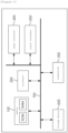
- FIG. 1 is a block diagram of a battery system to which embodiments of the present invention may be applied.
- a battery pack or battery module may include a plurality of battery cells connected in series.
- the battery pack or module may be connected to a load through a positive terminal and a negative terminal to perform charging or discharging.
- the most commonly used battery cell is a lithium-ion (Li-Ion) battery cell.
- a battery management system may be connected to a battery module or battery pack.
- the battery management system may monitor a current, a voltage and a temperature of each battery cell or module to be managed, calculate a state of charge (SOC) of the battery based on monitoring results to control charging and discharging.
- SOC State of Charge
- SOH State of Health
- the BMS may monitor battery cells, read cell voltages, and transmit them to other systems connected to the battery.
- the battery management system monitors at least one electrical component constituting the battery system and passes their status data on to other systems.
- the BMS includes a communication module for communicating with other systems in a device including the battery system.
- the communication module of the BMS can communicate with other systems in the device using CAN (Controller Area Network).
- CAN Controller Area Network
- components, modules or systems in the BMS are connected to each other through a CAN bus.
- the battery management system (BMS) may use CAN communication to remotely transmit status data obtained through monitoring of the battery pack or module and at least one electrical component constituting the battery management system (BMS) to other systems.
- the battery management system may equally balance charges of the battery cells in order to extend the life of the battery system.
- the BMS may include various components such as a fuse, a current sensing element, a thermistor, a switch, and a balancer to perform such operations.
- a micro controller unit (MCU) or a battery monitoring integrated chip (BMIC) for interworking with and controlling these components is additionally included in the BMS.
- the BMIC may be located inside the battery management system (BMS) and may be an IC-type component that measures information such as voltage, temperature, and current of the battery cell/module.
- a battery management system (BMS) may be applied to an automobile.
- a battery management system (BMS) is connected with a battery protection apparatus, and the battery protection apparatus blocks a charging and discharging circuit when a battery abnormality occurs.
- BMS battery management system
- a general battery protection circuit limits use of the battery by blocking the charging and discharging circuit when an abnormality occurs in any one battery cell or module.
- FIG. 2 is a block diagram of a battery protection apparatus according to embodiments of the present invention.
- the battery protection apparatus may control charging and discharging operation of a battery cell by comparing a charging period of time at a certain temperature with a preset condition value if at least one battery cell in the battery system operates below a preset threshold temperature.
- the battery protection apparatus may calculate accumulated charging time period of the battery cells to be charged below or equal to a predetermined threshold temperature and permanently control operation of the battery cells.
- the battery protection apparatus may include a memory 100, a processor 200, a transceiver 300, an input interface 400, an output interface 500, and a storage device 600.
- respective components 100, 200, 300, 400, 500, 600 included in the battery protection apparatus may be connected by a bus 700 to communicate with each other.
- the memory 100 and the storage device 600 among the components 100, 200, 300, 400, 500, 600 may include at least one of a volatile storage medium and a non-volatile storage medium.
- the memory 100 and the storage device 600 may include at least one of read only memory (ROM) and random access memory (RAM).
- the memory 100 may include at least one instruction executed by the processor 200.
- the at least one instruction may include an instruction to check accumulated charging time period of charging current applied to the battery cell under a temperature condition less than or equal to a predetermined threshold temperature; and an instruction to determine whether to permanently block charging and discharging of the battery cell by comparing the accumulated charging time period with a predetermined threshold time period.
- the instruction to determine whether to permanently block charging and discharging of the battery cell may include an instruction to permanently block charging and discharging of the battery cell in the instance that the accumulated charging time period is greater than or equal to the threshold time period.
- the instruction to determine whether to permanently block charging and discharging of the battery cell may include: an instruction to identify the operation mode of the battery cell in the instance that the accumulated charging time period is less than the threshold time period; and an instruction to compare the charging time period of the battery cell under the temperature condition less than or equal to the predetermined threshold temperature according to the operation mode with at least one predefined time period and to control charging and discharging of the battery cell according to the comparison result.
- the instruction to control charging and discharging of the battery cell may include an instruction to: upon the battery cell being charged for more than or equal to a first time period under the temperature condition of less than or equal to the threshold temperature in a charge mode, control the battery system to prevent charging of the battery cell by transmitting a first control signal to the battery system.
- the instruction to control charging and discharging of the battery cell may include an instruction to: upon the battery cell being charged for more than or equal to a second time period under the temperature condition of less than or equal to the threshold temperature in the charge mode, transmit a second control signal to the battery cell to block a charging switch of the battery cell to prevent charging of the battery cell.
- the instruction to control charging and discharging of the battery cell may include an instruction to: upon the battery cell being charged for more than or equal to a third time period under a temperature condition of less than or equal to a predefined first discharge temperature in a discharge mode, transmit a third control signal to the battery system to control an amount of output current of the battery cell.
- the instruction to control the amount of output current may include an instruction to control reducing the amount of output current required for the battery cell to a threshold value or less in the discharge mode.
- the instruction to control charging and discharging of the battery cell may include an instruction to: upon the battery cell being charged for more than or equal to a fourth time period under a temperature condition of less than or equal to a predefined second discharge temperature in a discharge mode, transmit a fourth control signal to the battery system to block a switch within the battery system to prevent discharging of the battery cell.
- the instruction to control charging and discharging of the battery cell may include an instruction to: upon the battery cell being charged for more than or equal to a fifth time period under a temperature condition of less than or equal to a predefined third discharge temperature in a discharge mode, transmit a fifth control signal to the battery cell to block a discharge switch of the battery cell.
- the charging of the battery cell according to the operation mode may be generated by a charger in the charge mode and by regenerative braking current in the discharge mode.
- the instruction to determine whether to permanently block charging and discharging of the battery cell may include an instruction to update the accumulated charging time period by reflecting the charging time in the accumulated charging time period.
- the predetermined threshold time period may be a predetermined period as a charging time period during which lithium plating does not occur in the battery cell by adjusting a charging time period of the battery cell at a certain temperature.
- the processor 200 may mean a central processing unit (CPU), a graphics processing unit (GPU), or a dedicated processor on which methods according to embodiments of the present invention are performed.
- CPU central processing unit
- GPU graphics processing unit
- dedicated processor on which methods according to embodiments of the present invention are performed.
- the processor 200 may execute at least one program command stored in the memory 100 as described above.
- FIG. 3 is a flowchart for explaining a battery protection method operated by a processor in a battery protection apparatus according to embodiments of the present invention.
- the battery protection apparatus may identify an accumulated charging period of time during which charging current is applied to at least one battery cell according to operations of the processor 200 (S1000).
- the battery protection apparatus may identify a accumulated charging period of time during which charging current is applied to at least one battery cell below a preset threshold temperature. In other words, the battery protection apparatus may check the accumulated charging period of time that accumulates the period during which the battery cell is charged equal to or under a temperature condition below a predetermined threshold temperature.
- the predetermined threshold temperature may be 0°C or lower.
- the battery protection apparatus may determine whether to permanently block the battery cell based on the accumulated charging time period (S5000).
- FIG. 4 is a flowchart illustrating a method of determining whether to permanently block a battery cell among the battery protection methods according to embodiments of the present invention.
- the battery protection apparatus may then compare the accumulated charging time period with a predefined threshold period of time (S1100).
- the predefined threshold period of time is information determined according to experimental data conducted in advance as follows and may be adjusted and predetermined to a charging time period of charging current applied to the battery at a certain temperature so that the determined charging time period ensures no lithium plating occurring in the battery cell.
- Battery cells with an initial voltage of 4.1V under a temperature condition of -20°C or lower were prepared. Afterwards, the charging and discharging cycles of the battery cells were applied differently at 10, 30, 50, 100 and 500 times, in other words, the charging time periods of the charging currents were set differently and charging current was applied at 5A per 0.25 seconds.
- a 5 second pause was interposed between charging and discharging operations. Thereafter, monitoring on whether lithium is deposited in the battery cell is performed, and any one of at least one charging time period in which lithium is not deposited may be selected as a threshold period of time.
- the selected threshold period of time may be used as comparison data with the accumulated charging period of the battery cell in the battery protection apparatus according to embodiments of the present invention.
- the battery protection apparatus may permanently block charging and discharging operations of the battery cell when the accumulated charging period of time is equal to or more than the predetermined threshold time period (S5100).
- the battery protection apparatus may control charging and discharging operations of the battery cell when the accumulated charging period is less than the predetermined threshold time period (S5500).
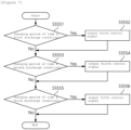
- FIG. 5 is a flowchart illustrating a method of controlling charging and discharging operations of a battery cell in a battery protection method according to embodiments of the present invention.
- the battery protection apparatus may identify an operation mode of the battery cell when the accumulated charging time period is less than the predetermined threshold time period (S5510).
- the battery protection apparatus may control charging and discharging operations of the battery cell by comparing the charging time period with preset conditions according to the operation mode of the battery cell (S5530).
- the battery protection apparatus may transmit a control signal corresponding to the condition to an operating subject, thereby controlling charging and discharging operations of the battery cell.
- the charging time period may be a charging period of time during which charging current is applied to the battery cell.
- it may be a charging time period during which the battery cell is being charged.
- the preset condition may be a charging period in which the battery is continuously being charged at a preset threshold temperature.
- the battery protection apparatus may update the accumulated charging period by reflecting the charging period into the accumulated charging period (S5570).
- FIG. 6 is a flowchart for explaining operations according to control signals in charge mode among the battery protection method according to embodiments of the present invention.
- the battery protection apparatus may check whether the charging time period satisfies a first charge condition (S5531).
- the battery protection apparatus when the battery protection apparatus operates in a charge mode, if charging of the battery cell continues for longer than a first time period under a temperature condition equal to or below a predetermined threshold temperature, the battery protection apparatus may output a first control signal and transmit it to the battery system (S5533).
- the predetermined threshold temperature may be 0°C and the first time period may be 1 second.
- the battery system may control to prevent inflow of charging current applied to the battery cell. In other words, the battery system may stop charging the battery cell.
- the battery protection apparatus may transmit a first release signal to the battery system when the temperature of the battery cell exceeds the predetermined threshold temperature and continues for equal to or longer than a second time period and the accumulated charging time period is less than the predetermined threshold time period. In other words, the battery protection apparatus may cancel the interruption of charging of the battery cells of the battery system.
- the battery system may control the charging current to flow into the battery cell to re-charge the battery cells.
- the predetermined threshold temperature may be 0°C
- the second time period may be 3 seconds
- the predetermined threshold period may be less than 25sec.
- the battery protection apparatus may check whether the charging time period satisfies a second charging condition (S5535).
- the battery protection apparatus when the battery protection apparatus operates in a charge mode, if charging of the battery cell continues for more than a second time period under a temperature condition equal to or below the predetermined threshold temperature, the battery protection apparatus may output a second control signal and transmit it to the battery cells (S5537).
- the predetermined threshold temperature may be 0°C
- the second time period may be 3 seconds
- the preset threshold period may be less than 25sec.
- the battery system may block a charge switch to prevent the charging current from flowing into the battery cells.
- the charge switch may be a charge-FET (C-FET).
- the battery protection apparatus may transmit a second release signal to the battery system if battery cell charging continues for a second time period during which the temperature of the battery cell exceeds the predetermined threshold temperature and if the accumulated charging time period is less than the predetermined threshold time period. Accordingly, the battery cells may resume charging by connecting the charge switch.
- the predetermined threshold temperature may be 0°C
- the second time period may be 3 seconds
- the preset threshold period may be 25sec.
- FIG. 7 is a flowchart for explaining operations according to control signals in a discharge mode among the battery protection methods according to embodiments of the present invention.
- the charging when the battery protection apparatus is in discharge mode, the charging may be done by regenerative braking current. In other words, charging may be performed when the battery protection apparatus is in a discharge mode.
- the battery protection apparatus may identify whether the charging period of the charging current by the regenerative current satisfies a first discharge condition (S5551).
- the battery protection apparatus when the battery protection apparatus operates in a discharge mode, if charging of the battery cell continues for more than a third time period at a first discharge temperature or less, the battery protection apparatus may output a third control signal and transmit it to the battery system (S5552).
- the third control signal may be an output control signal.
- the first discharge temperature may be -20°C
- the third time period may be 1 second.
- the battery system may control the output of the battery cells by reducing the amount of output current required for the battery cells.
- the battery protection apparatus may transmit a third release signal to the battery system when the temperature of the battery cells rises above the predetermined threshold temperature and the accumulated charging period is less than the predetermined threshold period. Accordingly, the battery system may stop output control of the battery cells, so that the battery cells may be discharged as its original state.
- the battery protection apparatus may check whether the charging period of the charging current by the regenerative current satisfies a second discharge condition (S5553).
- the battery protection apparatus when the battery protection apparatus operates in a discharge mode, if charging of the battery cell continues for more than a fourth time period at a second discharge temperature or lower, the battery protection apparatus may output a fourth control signal and transmit it to the battery system(S5554).
- the battery system may block discharging of the battery cell when the fourth control signal is received.
- the second discharge temperature may be -20°C
- the fourth period may be 1 second.
- the battery protection apparatus may transmit a fourth release signal to the battery system. Accordingly, the battery system may cancel the blocking of battery cell discharge. In other words, the battery cells may be re-discharged.
- the battery protection apparatus may check whether the charging period of the charging current by the regenerative braking current satisfies a third discharge condition (S5555).
- the battery protection apparatus when the battery protection apparatus operates in a discharge mode, if charging of the battery cell continues for more than a fifth time period under a temperature condition equal to or below the third discharge temperature, the battery protection apparatus may output a fifth control signal and transmit it to the battery cells (S5556).
- the third discharge temperature may be -20°C
- the fifth time period may be 3 seconds.
- the battery cell when it receives the fifth control signal, it may block a discharge switch to prevent charging current from flowing into the battery cell.
- the discharge switch may be a discharge-FET (D-FET).
- the battery protection apparatus may transmit the fifth release signal to the battery system.
- the battery cells may resume discharging by connecting the discharge switch.
- the battery protecting device and method according to embodiments of the present invention may identify accumulated charging time period of charging current applied to the battery cell and determine whether to permanently block charging and discharging of the battery cell by comparing the accumulated charging time period with a predetermined threshold time period, thereby preventing battery cell ignition due to lithium plating occurring in the battery cell caused from charging current.
- the operations of the method according to the embodiments and the experiment examples of the present invention may be implemented as a computer-readable program or code on a computer-readable recording medium.
- the computer-readable recording medium includes all types of recording devices in which data readable by a computer system is stored.
- the computer-readable recording medium may be distributed in a network-connected computer system to store and execute computer-readable programs or codes in a distributed manner.
- the computer-readable recording medium may include hardware devices specially configured to store and execute program instructions, such as ROM, RAM, flash memory, etc.
- the program instructions may include not only machine language code created by a compiler, but also high-level language code that can be executed by a computer using an interpreter.
- a block or apparatus corresponds to a method step or feature of a method step.
- aspects described in the context of a method may also represent a feature of a corresponding block or item or a corresponding apparatus.
- Some or all of the method steps may be performed by (or using) a hardware device, such as, for example, a microprocessor, a programmable computer, or an electronic circuit. In some embodiments, one or more of the most important method steps may be performed by such an apparatus.
Landscapes
- Engineering & Computer Science (AREA)
- Power Engineering (AREA)
- Manufacturing & Machinery (AREA)
- Chemical & Material Sciences (AREA)
- Chemical Kinetics & Catalysis (AREA)
- Electrochemistry (AREA)
- General Chemical & Material Sciences (AREA)
- Transportation (AREA)
- Mechanical Engineering (AREA)
- Life Sciences & Earth Sciences (AREA)
- Sustainable Development (AREA)
- Sustainable Energy (AREA)
- Microelectronics & Electronic Packaging (AREA)
- Charge And Discharge Circuits For Batteries Or The Like (AREA)
- Secondary Cells (AREA)
- Protection Of Static Devices (AREA)
Applications Claiming Priority (2)
| Application Number | Priority Date | Filing Date | Title |
|---|---|---|---|
| KR1020220114087A KR20240035075A (ko) | 2022-09-08 | 2022-09-08 | 배터리 보호 장치 및 방법 |
| PCT/KR2023/011910 WO2024053881A1 (ko) | 2022-09-08 | 2023-08-11 | 배터리 보호 장치 및 방법 |
Publications (3)
| Publication Number | Publication Date |
|---|---|
| EP4406770A1 true EP4406770A1 (de) | 2024-07-31 |
| EP4406770A4 EP4406770A4 (de) | 2025-04-23 |
| EP4406770B1 EP4406770B1 (de) | 2026-02-11 |
Family
ID=90191311
Family Applications (1)
| Application Number | Title | Priority Date | Filing Date |
|---|---|---|---|
| EP23863361.4A Active EP4406770B1 (de) | 2022-09-08 | 2023-08-11 | Batterieschutzvorrichtung und -verfahren |
Country Status (7)
| Country | Link |
|---|---|
| US (1) | US20240421616A1 (de) |
| EP (1) | EP4406770B1 (de) |
| JP (1) | JP7838881B2 (de) |
| KR (1) | KR20240035075A (de) |
| CN (1) | CN118354925A (de) |
| ES (1) | ES3063594T3 (de) |
| WO (1) | WO2024053881A1 (de) |
Family Cites Families (18)
| Publication number | Priority date | Publication date | Assignee | Title |
|---|---|---|---|---|
| JP5368038B2 (ja) | 2008-09-11 | 2013-12-18 | ミツミ電機株式会社 | 電池状態検知装置及びそれを内蔵する電池パック |
| JP2010086746A (ja) | 2008-09-30 | 2010-04-15 | Sanyo Electric Co Ltd | パック電池およびその制御方法 |
| JPWO2011004550A1 (ja) | 2009-07-10 | 2012-12-13 | パナソニック株式会社 | サイクル数計数回路、電池パック、及び電池システム |
| KR101174895B1 (ko) * | 2010-09-02 | 2012-08-17 | 삼성에스디아이 주식회사 | 배터리 팩, 및 이의 제어방법 |
| CN104145400B (zh) * | 2012-02-29 | 2017-02-22 | Nec能源元器件株式会社 | 电池控制系统、电池组、电子设备和充电器 |
| WO2014044292A1 (en) * | 2012-09-18 | 2014-03-27 | Phonak Ag | Method for charging a nimh battery, a battery charger and a system comprising a battery charger and a hearing device |
| JP5954144B2 (ja) | 2012-11-30 | 2016-07-20 | ソニー株式会社 | 制御装置、制御方法、制御システムおよび電動車両 |
| FR3005208B1 (fr) * | 2013-04-30 | 2015-04-24 | Renault Sa | Procede de gestion de la temperature d'une batterie de vehicule electrique ou hybride. |
| KR20150077666A (ko) * | 2013-12-30 | 2015-07-08 | 삼성전자주식회사 | 배터리 팩, 이를 포함하는 전자 장치 및 충전 제어 방법 |
| KR20160077882A (ko) * | 2014-12-24 | 2016-07-04 | 주식회사 엘지화학 | 배터리 팩의 충방전 제어방법 |
| JP7245446B2 (ja) * | 2018-10-03 | 2023-03-24 | カシオ計算機株式会社 | 充電装置、充電方法及びプログラム |
| JP6639720B1 (ja) * | 2019-04-09 | 2020-02-05 | 日本たばこ産業株式会社 | 吸引装置に具備される電源ユニット、吸引装置、及び電源ユニットを動作させる方法 |
| CN110091748B (zh) * | 2019-05-21 | 2021-09-03 | 广州小鹏汽车科技有限公司 | 电动车辆充电异常的处理方法、装置和车辆 |
| KR102858853B1 (ko) | 2020-03-11 | 2025-09-11 | 주식회사 엘지에너지솔루션 | 이차전지 및 이의 리튬 석출 검출 방법 |
| CN115103738A (zh) | 2020-06-29 | 2022-09-23 | 应用材料公司 | Cmp中的温度和浆体流动速率控制 |
| KR102188634B1 (ko) * | 2020-07-03 | 2020-12-08 | 주식회사 에코전력 | 이모빌리티용 스마트 배터리 모니터링 시스템 |
| JP2022039880A (ja) * | 2020-08-26 | 2022-03-10 | レシップホールディングス株式会社 | 充電システム |
| CN114047448A (zh) * | 2021-10-25 | 2022-02-15 | 安徽锐能科技有限公司 | 自适应充电剩余时间估算方法、装置、系统及存储介质 |
-
2022
- 2022-09-08 KR KR1020220114087A patent/KR20240035075A/ko active Pending
-
2023
- 2023-08-11 JP JP2024524460A patent/JP7838881B2/ja active Active
- 2023-08-11 CN CN202380014514.XA patent/CN118354925A/zh active Pending
- 2023-08-11 ES ES23863361T patent/ES3063594T3/es active Active
- 2023-08-11 EP EP23863361.4A patent/EP4406770B1/de active Active
- 2023-08-11 US US18/703,120 patent/US20240421616A1/en active Pending
- 2023-08-11 WO PCT/KR2023/011910 patent/WO2024053881A1/ko not_active Ceased
Also Published As
| Publication number | Publication date |
|---|---|
| EP4406770A4 (de) | 2025-04-23 |
| ES3063594T3 (en) | 2026-04-17 |
| US20240421616A1 (en) | 2024-12-19 |
| JP7838881B2 (ja) | 2026-04-01 |
| JP2024539259A (ja) | 2024-10-28 |
| KR20240035075A (ko) | 2024-03-15 |
| EP4406770B1 (de) | 2026-02-11 |
| CN118354925A (zh) | 2024-07-16 |
| WO2024053881A1 (ko) | 2024-03-14 |
Similar Documents
| Publication | Publication Date | Title |
|---|---|---|
| KR102365552B1 (ko) | 다수의 병렬 연결된 고전압 배터리 제어 장치 및 그 방법 | |
| CN112736311B (zh) | 蓄电池的充电方法、装置和电子设备 | |
| CN103085669A (zh) | 自动碰撞电池放电方法 | |
| WO2006045016A2 (en) | Integrated drop-in lithium battery substitute for lead-acid batteries | |
| KR101940704B1 (ko) | 병렬 연결된 배터리 팩의 soc 및 soh 관리 장치 및 방법 | |
| EP4425646B1 (de) | Batterieverwaltungsvorrichtung und -verfahren | |
| EP1340992B1 (de) | Verfahren und Vorrichtung zur Steuerung des Ladens und Entladens eines Batteriepacks | |
| EP4518089A1 (de) | Batterieladesteuerungsvorrichtung und -verfahren sowie batteriesystem damit | |
| US12571847B2 (en) | Battery pack and method of controlling the same | |
| EP4406770A1 (de) | Batterieschutzvorrichtung und -verfahren | |
| US20250046890A1 (en) | Battery management device, battery pack, and battery pack charging control method | |
| EP4550618A1 (de) | Verfahren und vorrichtung zur steuerung des batterieladens | |
| EP4404417B1 (de) | Batteriesteuerungssystem und verfahren zur verwaltung des batteriezustands | |
| EP4321885B1 (de) | Vorrichtung und verfahren zur diagnose von schäden an einem schalter in einer batterieschutzschaltung und batterieverwaltungsvorrichtung damit | |
| EP4521590A1 (de) | Vorrichtung und verfahren zur diagnose des zustands einer batterie | |
| WO2024028955A1 (ja) | 電池制御方法、電池制御装置、及び車両制御方法 | |
| EP4546607A1 (de) | Batterieverwaltungsvorrichtung, batteriesystem und batteriemodulanordnungsausgleichsverfahren | |
| EP4361653A1 (de) | Vorrichtung und verfahren zur verwaltung einer batterie | |
| KR102550097B1 (ko) | Bms가 구비되지 않은 배터리 시스템용 충전기 | |
| EP4459298A1 (de) | Diagnosevorrichtung und -verfahren für batteriesystem | |
| KR20210111473A (ko) | 패시브 밸런싱을 통한 배터리 관리 장치 및 동작 방법 | |
| US20250141213A1 (en) | Vehicle impact detection device | |
| KR20260037816A (ko) | 배터리 제어 장치 및 방법, 그리고 이를 포함하는 차량용 배터리 시스템 | |
| KR20240093318A (ko) | 배터리 상태 진단 장치 및 방법 | |
| KR20240172836A (ko) | 배터리 충전 제어 장치 및 방법, 그리고 이를 포함하는 배터리 시스템 |
Legal Events
| Date | Code | Title | Description |
|---|---|---|---|
| STAA | Information on the status of an ep patent application or granted ep patent |
Free format text: STATUS: THE INTERNATIONAL PUBLICATION HAS BEEN MADE |
|
| PUAI | Public reference made under article 153(3) epc to a published international application that has entered the european phase |
Free format text: ORIGINAL CODE: 0009012 |
|
| STAA | Information on the status of an ep patent application or granted ep patent |
Free format text: STATUS: REQUEST FOR EXAMINATION WAS MADE |
|
| 17P | Request for examination filed |
Effective date: 20240423 |
|
| AK | Designated contracting states |
Kind code of ref document: A1 Designated state(s): AL AT BE BG CH CY CZ DE DK EE ES FI FR GB GR HR HU IE IS IT LI LT LU LV MC ME MK MT NL NO PL PT RO RS SE SI SK SM TR |
|
| A4 | Supplementary search report drawn up and despatched |
Effective date: 20250324 |
|
| RIC1 | Information provided on ipc code assigned before grant |
Ipc: H01M 10/48 20060101ALI20250318BHEP Ipc: B60L 58/16 20190101ALI20250318BHEP Ipc: B60L 3/12 20060101ALI20250318BHEP Ipc: H01M 10/42 20060101ALI20250318BHEP Ipc: H01M 10/44 20060101ALI20250318BHEP Ipc: H02J 7/00 20060101ALI20250318BHEP Ipc: B60L 7/10 20060101ALI20250318BHEP Ipc: B60L 58/12 20190101ALI20250318BHEP Ipc: B60L 58/18 20190101ALI20250318BHEP Ipc: B60L 3/00 20190101AFI20250318BHEP |
|
| GRAP | Despatch of communication of intention to grant a patent |
Free format text: ORIGINAL CODE: EPIDOSNIGR1 |
|
| STAA | Information on the status of an ep patent application or granted ep patent |
Free format text: STATUS: GRANT OF PATENT IS INTENDED |
|
| RIC1 | Information provided on ipc code assigned before grant |
Ipc: B60L 3/00 20190101AFI20250806BHEP Ipc: B60L 58/18 20190101ALI20250806BHEP Ipc: B60L 58/12 20190101ALI20250806BHEP Ipc: B60L 7/10 20060101ALI20250806BHEP Ipc: H02J 7/00 20060101ALI20250806BHEP Ipc: H01M 10/44 20060101ALI20250806BHEP Ipc: H01M 10/42 20060101ALI20250806BHEP Ipc: B60L 3/12 20060101ALI20250806BHEP Ipc: B60L 58/16 20190101ALI20250806BHEP Ipc: H01M 10/48 20060101ALI20250806BHEP |
|
| DAV | Request for validation of the european patent (deleted) | ||
| DAX | Request for extension of the european patent (deleted) | ||
| INTG | Intention to grant announced |
Effective date: 20250908 |
|
| P01 | Opt-out of the competence of the unified patent court (upc) registered |
Free format text: CASE NUMBER: UPC_APP_8757_4406770/2025 Effective date: 20251002 |
|
| GRAS | Grant fee paid |
Free format text: ORIGINAL CODE: EPIDOSNIGR3 |
|
| GRAA | (expected) grant |
Free format text: ORIGINAL CODE: 0009210 |
|
| STAA | Information on the status of an ep patent application or granted ep patent |
Free format text: STATUS: THE PATENT HAS BEEN GRANTED |
|
| AK | Designated contracting states |
Kind code of ref document: B1 Designated state(s): AL AT BE BG CH CY CZ DE DK EE ES FI FR GB GR HR HU IE IS IT LI LT LU LV MC ME MK MT NL NO PL PT RO RS SE SI SK SM TR |
|
| REG | Reference to a national code |
Ref country code: CH Ref legal event code: F10 Free format text: ST27 STATUS EVENT CODE: U-0-0-F10-F00 (AS PROVIDED BY THE NATIONAL OFFICE) Effective date: 20260211 Ref country code: GB Ref legal event code: FG4D |
|
| REG | Reference to a national code |
Ref country code: DE Ref legal event code: R096 Ref document number: 602023012014 Country of ref document: DE |
|
| REG | Reference to a national code |
Ref country code: IE Ref legal event code: FG4D |
|
| REG | Reference to a national code |
Ref country code: ES Ref legal event code: FG2A Ref document number: 3063594 Country of ref document: ES Kind code of ref document: T3 Effective date: 20260417 |