EP4404832B1 - Systeme und verfahren zur korrektur eines ekg-signals in einer mrt-umgebung - Google Patents
Systeme und verfahren zur korrektur eines ekg-signals in einer mrt-umgebung Download PDFInfo
- Publication number
- EP4404832B1 EP4404832B1 EP22790505.6A EP22790505A EP4404832B1 EP 4404832 B1 EP4404832 B1 EP 4404832B1 EP 22790505 A EP22790505 A EP 22790505A EP 4404832 B1 EP4404832 B1 EP 4404832B1
- Authority
- EP
- European Patent Office
- Prior art keywords
- mri
- patient
- ecg signal
- correction factor
- camera
- Prior art date
- Legal status (The legal status is an assumption and is not a legal conclusion. Google has not performed a legal analysis and makes no representation as to the accuracy of the status listed.)
- Active
Links
Images


Classifications
-
- A—HUMAN NECESSITIES
- A61—MEDICAL OR VETERINARY SCIENCE; HYGIENE
- A61B—DIAGNOSIS; SURGERY; IDENTIFICATION
- A61B5/00—Measuring for diagnostic purposes; Identification of persons
- A61B5/0059—Measuring for diagnostic purposes; Identification of persons using light, e.g. diagnosis by transillumination, diascopy, fluorescence
- A61B5/0077—Devices for viewing the surface of the body, e.g. camera, magnifying lens
-
- A—HUMAN NECESSITIES
- A61—MEDICAL OR VETERINARY SCIENCE; HYGIENE
- A61B—DIAGNOSIS; SURGERY; IDENTIFICATION
- A61B5/00—Measuring for diagnostic purposes; Identification of persons
- A61B5/05—Detecting, measuring or recording for diagnosis by means of electric currents or magnetic fields; Measuring using microwaves or radio waves
- A61B5/055—Detecting, measuring or recording for diagnosis by means of electric currents or magnetic fields; Measuring using microwaves or radio waves involving electronic [EMR] or nuclear [NMR] magnetic resonance, e.g. magnetic resonance imaging
-
- A—HUMAN NECESSITIES
- A61—MEDICAL OR VETERINARY SCIENCE; HYGIENE
- A61B—DIAGNOSIS; SURGERY; IDENTIFICATION
- A61B5/00—Measuring for diagnostic purposes; Identification of persons
- A61B5/24—Detecting, measuring or recording bioelectric or biomagnetic signals of the body or parts thereof
- A61B5/316—Modalities, i.e. specific diagnostic methods
- A61B5/318—Heart-related electrical modalities, e.g. electrocardiography [ECG]
- A61B5/346—Analysis of electrocardiograms
- A61B5/349—Detecting specific parameters of the electrocardiograph cycle
- A61B5/355—Detecting T-waves
-
- A—HUMAN NECESSITIES
- A61—MEDICAL OR VETERINARY SCIENCE; HYGIENE
- A61B—DIAGNOSIS; SURGERY; IDENTIFICATION
- A61B5/00—Measuring for diagnostic purposes; Identification of persons
- A61B5/72—Signal processing specially adapted for physiological signals or for diagnostic purposes
- A61B5/7271—Specific aspects of physiological measurement analysis
- A61B5/7285—Specific aspects of physiological measurement analysis for synchronizing or triggering a physiological measurement or image acquisition with a physiological event or waveform, e.g. an ECG signal
- A61B5/7289—Retrospective gating, i.e. associating measured signals or images with a physiological event after the actual measurement or image acquisition, e.g. by simultaneously recording an additional physiological signal during the measurement or image acquisition
-
- G—PHYSICS
- G01—MEASURING; TESTING
- G01R—MEASURING ELECTRIC VARIABLES; MEASURING MAGNETIC VARIABLES
- G01R33/00—Arrangements or instruments for measuring magnetic variables
- G01R33/20—Arrangements or instruments for measuring magnetic variables involving magnetic resonance
- G01R33/44—Arrangements or instruments for measuring magnetic variables involving magnetic resonance using nuclear magnetic resonance [NMR]
- G01R33/48—NMR imaging systems
- G01R33/54—Signal processing systems, e.g. using pulse sequences ; Generation or control of pulse sequences; Operator console
- G01R33/56—Image enhancement or correction, e.g. subtraction or averaging techniques, e.g. improvement of signal-to-noise ratio and resolution
- G01R33/567—Image enhancement or correction, e.g. subtraction or averaging techniques, e.g. improvement of signal-to-noise ratio and resolution gated by physiological signals, i.e. synchronization of acquired MR data with periodical motion of an object of interest, e.g. monitoring or triggering system for cardiac or respiratory gating
- G01R33/5673—Gating or triggering based on a physiological signal other than an MR signal, e.g. ECG gating or motion monitoring using optical systems for monitoring the motion of a fiducial marker
Definitions
- Magnetic resonant imaging (MRI) scanners utilize magnetic fields, magnetic field gradients, and radio waves to generate a series of images of a patient.
- the MRI scanner may use a gating or trigger-mechanism.
- One such mechanism can be an electrocardiogram (ECG).
- ECG electrocardiogram
- An ECG signal includes a number of waves, segments, complexes, and intervals.
- the R-wave is often used to gate MRI image collection, storage, and/or transmission.
- United States patent application US20080114237A1 discloses a device for synchronizing a magnetic resonance unit with the cardiac rhythm of a patient, comprising a number of electrodes for leading off electrocardiogram signals from the body of the patient and an evaluation unit for determining a characteristic trigger time within a cardiac rhythm period of the patient from the electrocardiogram signals.
- the device allows reliable determination of characteristic trigger times within the cardiac rhythm period of the patient even with elevated magnetic field strengths and which operates at least largely independently of external magnetic field by comparing electrocardiogram signals obtained before and after the introduction of the patient into the magnetic resonance unit, in order to determine an enlargement of at least one characteristic of the electrocardiogram signals due to the magnetic field.
- the method's performance is evaluated in the context of 7 Tesla non-enhanced angiography of the lower extremities.
- This journal publication further discloses a basic algorithm capable of estimating in real-time the phase of the cardiac cycle from reflection photoplethysmography signals obtained from skin color variations of the forehead recorded with a video camera. Instead of finding the algorithm's parameters heuristically, they were optimized using videos of the forehead as well as electrocardiography and pulse oximetry signals that were recorded from eight healthy volunteers in and outside the scanner, with and without active radio frequency and gradient coils. Based on the video characteristics, synthetic signals were generated, and the "best available" values of an objective function were determined using mathematical optimization.
- the performance of the proposed method with optimized algorithm parameters was evaluated by applying it to the recorded videos and comparing the computed triggers to those of contact-based methods. Additionally, the method was evaluated by using its triggers for acquiring images from a healthy volunteer and comparing the result to images obtained using pulse oximetry triggering.
- the present disclosure is directed generally to systems and methods for correcting an electrocardiogram (ECG) signal impacted by the magnetohydrodynamic (MHD) effect.
- ECG electrocardiogram
- MHD magnetohydrodynamic
- the MHD effect occurs due to a patient undergoing magnetic resonant imaging (MRI).
- MRI magnetic resonant imaging
- the systems and methods derive patient information (such as heart rate) from images captured by a camera, and use this patient information to calculate a T-wave correction factor.
- This T-wave correction factor is used to counteract the amplification or distortion of the T-wave due to the MHD effect.
- An MRI scanner may then use the corrected ECG signal for more accurate gated imaging.
- an MRI gating system includes an ECG monitor.
- the ECG monitor is configured to capture an ECG signal of a patient.
- the MRI gating system further includes a camera.
- the camera is configured to capture a series of patient images.
- the camera is a high frame rate camera or a vital signs camera.
- the camera has a frame rate of at least 1,000 frames per second.
- the series of patient images capture a neck area of the patient.
- the MRI gating system further includes an image processing unit.
- the image processing unit (IPU) is configured to determine a T-wave correction factor.
- the T-wave correction factor is determined based on the series of patient images. According to an example, the T-wave correction factor is further based on a patient heart rate derived from the series of patient images.
- the T-wave correction factor is further based on a diameter of a carotid artery. Further, the T-wave correction factor may be further based on a blood flow velocity in the carotid artery.
- the T-wave correction factor is further based on a magnetic field incident upon the patient.
- the magnetic field may be generated by the MRI scanner.
- the MRI gating system further includes an MRI scanner.
- the MRI scanner is configured to generate a gated MRI image set.
- the gated MRI image set is generated based on the corrected ECG signal.
- the MRI scanner generates the gated MRI image set further based on one or more R-waves of the corrected ECG signal.
- an MHD effect correction system for an ECG signal.
- the MHD effect correction system includes a camera configured to capture a series of patient images.
- the MHD effect correction system further includes an image processing unit configured to (1) determine a T-wave correction factor based on the series of patient images and (2) generate a corrected ECG signal based on the ECG signal and the T-wave correction factor.
- a method for correcting an ECG signal for an MHD effect includes capturing, via a camera, a series of patient images. The method further includes determining, via a processor, a T-wave correction factor based on the series of patient images. The method further includes generating, via the processor, a corrected ECG signal based on a captured ECG signal and the T-wave correction factor. According to an example, the method further includes capturing, via an ECG monitor, the captured ECG signal. According to an example, the method further includes generating, via a magnetic resonating image (MRI) scanner, a gated MRI image set based on the corrected ECG signal.
- MRI magnetic resonating image
- a processor or controller may be associated with one or more storage media (generically referred to herein as "memory,” e.g., volatile and non-volatile computer memory such as RAM, PROM, EPROM, EEPROM, floppy disks, compact disks, optical disks, magnetic tape, SSD, etc.).
- the storage media may be encoded with one or more programs that, when executed on one or more processors and/or controllers, perform at least some of the functions discussed herein.
- Various storage media may be fixed within a processor or controller or may be transportable, such that the one or more programs stored thereon can be loaded into a processor or controller so as to implement various aspects as discussed herein.
- program or “computer program” are used herein in a generic sense to refer to any type of computer code (e.g., software or microcode) that can be employed to program one or more processors or controllers.
- the present disclosure is directed generally to systems and methods for correcting an electrocardiogram (ECG) impacted by the magnetohydrodynamic (MHD) effect.
- ECG electrocardiogram
- MHD magnetohydrodynamic
- the MHD effect occurs due to a patient undergoing magnetic resonant imaging (MRI).
- MRI magnetic resonant imaging
- the systems and methods derive patient information (such as heart rate) from images captured by a camera, and use this patient information to calculate a T-wave correction factor.
- This T-wave correction factor is used to counteract the amplification of the T-wave due to the MHD effect.
- An MRI scanner may then use the corrected ECG signal for more accurate gated imaging.
- FIG. 1 shows a system diagram for an MRI gating system 100.
- the MRI gating system 100 generates a gated MRI image set 126 based on a corrected ECG signal 118.
- the corrected ECG signal 118 is generated by IPU 106 based on patient images 116, captured by camera 104, and an ECG signal 110 captured by an ECG monitor 102.
- the primary purpose of the IPU 106 is to calculate the T-wave correction factor 114 for an ECG signal 110.
- the T-wave correction factor 114 is applied to the ECG signal 110 to compensate for the amplified T-wave due to the MHD effect.
- the IPU 108 may pre-process the images 116 using de-noising and/or frame stabilization algorithms 182. Once the images 116 have been pre-processed, the IPU 106 further processes the images 116 to determine the heart rate 120 of the patient 200.
- the patient heart rate 120 can be determined by analyzing the movement of the patient's skin around one of their carotid arteries 204 via the images 116 captured by a high frame rate camera 104.
- the diameter 206 of the carotid artery 204 may be provided to the IPU 106 by patient records or by a medical professional operating the MRI gating system 100. In further examples, the diameter 206 of the carotid artery 204 can be derived from the patient images 116.
- the magnitude 124 of the magnetic field 122 incident upon the patient 200, as well as the angle 128 between the magnetic field 122 and the blood flow direction 208 in the carotid artery, may be provided to the IPU 106 directly by the MRI scanner 108 or via a sensor within the MRI scanner 108.
- the corrected ECG signal 118 is then provided to the MRI scanner 108 for gated imaging.
- the MRI scanner 108 In gated imaging, the MRI scanner 108 continually generates MRI images, but only stores and/or transmits MRI images corresponding to a gating event or trigger.
- the MRI scanner 108 generates one or more gated images 126 based on the R-waves 130 of the corrected ECG signal 118. Accordingly, each of the gated images 126 corresponds to an R-wave 130 of one cycle of the ECG signal 110.
- Applying the T-wave correction factor 114 to the ECG signal 110 prevents the MRI scanner 108 from confusing the amplified T-waves with R-waves 130, thus preventing gating and/or triggering errors.
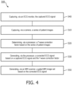
- a method 500 for correcting an ECG signal for an MHD effect includes capturing 510, via a camera, a series of patient images.
- the method 500 further includes determining 520, via a processor, a T-wave correction factor based on the series of patient images.
- the method 500 further includes generating 530, via the processor, a corrected ECG signal based on a captured ECG signal and the T-wave correction factor.
- the method 500 further includes capturing 540, via an ECG monitor, the captured ECG signal.
- the method 500 further includes generating 550, via a magnetic resonating image (MRI) scanner, a gated MRI image set based on the corrected ECG signal.
- MRI magnetic resonating image
- the phrase "at least one,” in reference to a list of one or more elements, should be understood to mean at least one element selected from any one or more of the elements in the list of elements, but not necessarily including at least one of each and every element specifically listed within the list of elements and not excluding any combinations of elements in the list of elements.
- This definition also allows that elements may optionally be present other than the elements specifically identified within the list of elements to which the phrase "at least one" refers, whether related or unrelated to those elements specifically identified.
- the present disclosure may be implemented as a system, a method, and/or a computer program product at any possible technical detail level of integration
- the computer program product may include a computer readable storage medium (or media) having computer readable program instructions thereon for causing a processor to carry out aspects of the present disclosure
- the computer readable storage medium can be a tangible device that can retain and store instructions for use by an instruction execution device.
- the computer readable storage medium may be, for example, but is not limited to, an electronic storage device, a magnetic storage device, an optical storage device, an electromagnetic storage device, a semiconductor storage device, or any suitable combination of the foregoing.
- a non-exhaustive list of more specific examples of the computer readable storage medium includes the following: a portable computer diskette, a hard disk, a random access memory (RAM), a read-only memory (ROM), an erasable programmable read-only memory (EPROM or Flash memory), a static random access memory (SRAM), a portable compact disc read-only memory (CD-ROM), a digital versatile disk (DVD), a memory stick, a floppy disk, a mechanically encoded device such as punch-cards or raised structures in a groove having instructions recorded thereon, and any suitable combination of the foregoing.
- RAM random access memory
- ROM read-only memory
- EPROM or Flash memory erasable programmable read-only memory
- SRAM static random access memory
- CD-ROM compact disc read-only memory
- DVD digital versatile disk
- memory stick a floppy disk
- a mechanically encoded device such as punch-cards or raised structures in a groove having instructions recorded thereon
- a computer readable storage medium is not to be construed as being transitory signals per se, such as radio waves or other freely propagating electromagnetic waves, electromagnetic waves propagating through a waveguide or other transmission media (e.g., light pulses passing through a fiber-optic cable), or electrical signals transmitted through a wire.
- Computer readable program instructions described herein can be downloaded to respective computing/processing devices from a computer readable storage medium or to an external computer or external storage device via a network, for example, the Internet, a local area network, a wide area network and/or a wireless network.
- the network may comprise copper transmission cables, optical transmission fibers, wireless transmission, routers, firewalls, switches, gateway computers and/or edge servers.
- a network adapter card or network interface in each computing/processing device receives computer readable program instructions from the network and forwards the computer readable program instructions for storage in a computer readable storage medium within the respective computing/processing device.
- the remote computer may be connected to the user's computer through any type of network, including a local area network (LAN) or a wide area network (WAN), or the connection may be made to an external computer (for example, through the Internet using an Internet Service Provider).
- electronic circuitry including, for example, programmable logic circuitry, field-programmable gate arrays (FPGA), or programmable logic arrays (PLA) may execute the computer readable program instructions by utilizing state information of the computer readable program instructions to personalize the electronic circuitry, in order to perform aspects of the present disclosure.
- the computer readable program instructions may also be loaded onto a computer, other programmable data processing apparatus, or other device to cause a series of operational steps to be performed on the computer, other programmable apparatus or other device to produce a computer implemented process, such that the instructions which execute on the computer, other programmable apparatus, or other device implement the functions/acts specified in the flowchart and/or block diagram block or blocks.
Landscapes
- Health & Medical Sciences (AREA)
- Life Sciences & Earth Sciences (AREA)
- Physics & Mathematics (AREA)
- Engineering & Computer Science (AREA)
- Biophysics (AREA)
- General Health & Medical Sciences (AREA)
- Molecular Biology (AREA)
- Public Health (AREA)
- Pathology (AREA)
- Biomedical Technology (AREA)
- Heart & Thoracic Surgery (AREA)
- Medical Informatics (AREA)
- Surgery (AREA)
- Animal Behavior & Ethology (AREA)
- Veterinary Medicine (AREA)
- Cardiology (AREA)
- Nuclear Medicine, Radiotherapy & Molecular Imaging (AREA)
- Physiology (AREA)
- Radiology & Medical Imaging (AREA)
- High Energy & Nuclear Physics (AREA)
- Signal Processing (AREA)
- Artificial Intelligence (AREA)
- Computer Vision & Pattern Recognition (AREA)
- Psychiatry (AREA)
- Power Engineering (AREA)
- Pulmonology (AREA)
- Condensed Matter Physics & Semiconductors (AREA)
- General Physics & Mathematics (AREA)
- Magnetic Resonance Imaging Apparatus (AREA)
- Measurement And Recording Of Electrical Phenomena And Electrical Characteristics Of The Living Body (AREA)
Claims (15)
- System (50) zur Korrektur eines magnetohydrodynamischen (MHD) Effekts für ein Elektrokardiogramm (EKG)-Signal (110), wobei das System dadurch gekennzeichnet ist, dass es umfasst:eine Kamera (104), die so konfiguriert ist, dass sie eine Reihe von Patientenbildern (112) erfasst; undeine Bildverarbeitungseinheit (106), die konfiguriert ist zum:Bestimmen eines T-Wellen-Korrekturfaktors (114) basierend auf der Reihe von Patientenbildern (116); undErzeugen eines korrigierten EKG-Signals (118) basierend auf dem EKG-Signal (110) und dem T-Wellen-Korrekturfaktor (114).
- Magnetresonanzbild-(MRT)-Gatingsystem (100), umfassend:einen Elektrokardiogramm-(EKG)-Monitor (102), der so konfiguriert ist, dass er ein EKG-Signal (110) eines Patienten (200) erfasst; und gekennzeichnet durchdas MHD-Effekt-Korrektursystem (50) nach Anspruch 1, das so konfiguriert ist, dass es ein korrigiertes EKG-Signal (118) erzeugt; undein MRT-Gerät (108), das so konfiguriert ist, dass es basierend auf dem korrigierten EKG-Signal (118) einen Gating-MRT-Bildsatz (126) erzeugt.
- MRT-Gating-System (100) nach Anspruch 2, wobei die Kamera (104) eine Kamera mit hoher Bildrate oder eine Vitalzeichenkamera ist.
- MRT-Gating-System (100) nach Anspruch 2, wobei die Kamera (104) eine Bildrate von mindestens 1.000 Bildern pro Sekunde aufweist.
- MRT-Gating-System (100) nach Anspruch 2, wobei der T-Wellen-Korrekturfaktor (114) weiter auf einer Patientenherzfrequenz (120) basiert, die aus der Reihe von Patientenbildern (116) abgeleitet ist.
- MRT-Gating-System (100) nach Anspruch 2, wobei der T-Wellen-Korrekturfaktor (114) weiter auf einer Größe (124) eines auf den Patienten (200) einfallenden Magnetfeldes (122) basiert.
- MRT-Gating-System (100) nach Anspruch 6, wobei das Magnetfeld (122) durch das MRT-Gerät (108) erzeugt wird.
- MRT-Gating-System (100) nach Anspruch 2, wobei die Reihe von Patientenbildern (116) einen Halsbereich (202) des Patienten (200) erfasst.
- MRT-Gating-System (100) nach Anspruch 8, wobei der T-Wellen-Korrekturfaktor (114) weiter auf einem Durchmesser (206) einer Halsschlagader (204) basiert.
- MRT- Gating-System (100) nach Anspruch 9, wobei der T-Wellen-Korrekturfaktor (114) weiter auf einer Blutflussgeschwindigkeit (208) in der Halsschlagader (204) basiert.
- MRT-Gating-System (100) nach Anspruch 9, wobei der T-Wellen-Korrekturfaktor (114) weiter auf einem Winkel (128) zwischen einem auf den Patienten (200) einfallenden Magnetfeld (122) und einer Blutflussrichtung (210) in der Halsschlagader (204) basiert.
- MRT-Gating-System (100) nach Anspruch 2, wobei das MRT-Gerät (108) den Gating-MRT-Bildsatz (126) weiter basierend auf einer oder mehreren R-Wellen (130) des korrigierten EKG-Signals (118) erzeugt.
- Verfahren (500) zum Korrigieren eines Elektrokardiogramm (EKG)-Signals hinsichtlich eines magnetohydrodynamischen (MHD) Effekts, wobei das Verfahren dadurch gekennzeichnet ist, dass es Folgendes umfasst:Erfassen (510) einer Reihe von Patientenbildern mit einer Kamera;Bestimmen (520) eines T-Wellen-Korrekturfaktors über einen Prozessor, basierend auf der Reihe von Patientenbildern; undErzeugen (530) eines korrigierten EKG-Signals über den Prozessor, basierend auf einem erfassten EKG-Signal und dem T-Wellen-Korrekturfaktor.
- Verfahren (500) nach Anspruch 13, weiter umfassend Erfassen (540) des erfassten EKG-Signals über einen EKG-Monitor.
- Verfahren (500) nach Anspruch 13, weiter umfassend Erzeugen (550), über ein Magnetresonanzbild(MRT)-Gerät, eines Gating-MRT-Bildsatzes basierend auf dem korrigierten EKG-Signal.
Applications Claiming Priority (2)
| Application Number | Priority Date | Filing Date | Title |
|---|---|---|---|
| US202163247410P | 2021-09-23 | 2021-09-23 | |
| PCT/EP2022/076326 WO2023046819A1 (en) | 2021-09-23 | 2022-09-22 | Systems and methods for correcting an ecg signal in an mri environment |
Publications (2)
| Publication Number | Publication Date |
|---|---|
| EP4404832A1 EP4404832A1 (de) | 2024-07-31 |
| EP4404832B1 true EP4404832B1 (de) | 2025-07-09 |
Family
ID=83898502
Family Applications (1)
| Application Number | Title | Priority Date | Filing Date |
|---|---|---|---|
| EP22790505.6A Active EP4404832B1 (de) | 2021-09-23 | 2022-09-22 | Systeme und verfahren zur korrektur eines ekg-signals in einer mrt-umgebung |
Country Status (5)
| Country | Link |
|---|---|
| US (1) | US20240398313A1 (de) |
| EP (1) | EP4404832B1 (de) |
| JP (1) | JP7650454B2 (de) |
| CN (1) | CN117979896A (de) |
| WO (1) | WO2023046819A1 (de) |
Family Cites Families (8)
| Publication number | Priority date | Publication date | Assignee | Title |
|---|---|---|---|---|
| JPS6392340A (ja) * | 1986-10-08 | 1988-04-22 | 株式会社日立製作所 | 磁気共鳴検査装置 |
| DE102006053613A1 (de) | 2006-11-14 | 2008-05-29 | Siemens Ag | Vorrichtung und Verfahren zum Synchronisieren einer Magnetresonanzanlage mit dem Herzrhytmus eines Patienten |
| EP2491858A1 (de) * | 2011-02-25 | 2012-08-29 | Max-Delbrück-Centrum Für Molekulare Medizin | MRT-Vorrichtung und Verfahren zum Betreiben einer MRT-Vorrichtung |
| US8467882B2 (en) | 2011-03-29 | 2013-06-18 | Medtronic, Inc. | Magnetic field detection using magnetohydrodynamic effect |
| JP6647831B2 (ja) | 2014-11-06 | 2020-02-14 | キヤノンメディカルシステムズ株式会社 | 信号処理装置、撮像装置及び信号処理方法 |
| JP2017035131A (ja) | 2015-08-06 | 2017-02-16 | 東芝メディカルシステムズ株式会社 | Ecg信号処理装置、mri装置及びecg信号処理方法 |
| EP3375354A1 (de) | 2017-03-17 | 2018-09-19 | Koninklijke Philips N.V. | Aus optischen bildern abgeleitetes herzbewegungssignal |
| CN112932455A (zh) | 2021-01-28 | 2021-06-11 | 上海联影医疗科技股份有限公司 | 磁共振成像设备及磁共振扫描方法 |
-
2022
- 2022-09-22 WO PCT/EP2022/076326 patent/WO2023046819A1/en not_active Ceased
- 2022-09-22 EP EP22790505.6A patent/EP4404832B1/de active Active
- 2022-09-22 JP JP2024515079A patent/JP7650454B2/ja active Active
- 2022-09-22 US US18/693,972 patent/US20240398313A1/en active Pending
- 2022-09-22 CN CN202280064247.2A patent/CN117979896A/zh active Pending
Also Published As
| Publication number | Publication date |
|---|---|
| CN117979896A (zh) | 2024-05-03 |
| WO2023046819A1 (en) | 2023-03-30 |
| EP4404832A1 (de) | 2024-07-31 |
| JP2024531608A (ja) | 2024-08-29 |
| JP7650454B2 (ja) | 2025-03-25 |
| US20240398313A1 (en) | 2024-12-05 |
Similar Documents
| Publication | Publication Date | Title |
|---|---|---|
| US10219712B2 (en) | ECG waveform detecting apparatus and imaging apparatus | |
| US11026636B2 (en) | Method for generating a medical data set of a moving body part | |
| EP3413075B1 (de) | Mri mit erzeugung eines physiologischen bewegungssignals unter verwendung eines pilotton-navigators | |
| US10546367B2 (en) | Device and method for improving medical image quality | |
| NL2022109B1 (en) | Heartbeat based selection of images for cardiovascular model | |
| US10646165B2 (en) | Removing eletrophysicologic artifacts from a magnetic resonance imaging system | |
| US20160106328A1 (en) | Determining arterial pulse transit time from time-series signals obtained at proximal and distal arterial sites | |
| US11406305B2 (en) | Signal quality metric for cardiovascular time series | |
| US20050207538A1 (en) | Method of determining an image from an image sequence | |
| EP3579244B1 (de) | Verfahren zum erzeugen eines bewegungssignals eines objekts | |
| JPS61115539A (ja) | デイジタル型x線撮影装置 | |
| US11083404B2 (en) | Processing apparatus for processing a physiological signal | |
| JP6647831B2 (ja) | 信号処理装置、撮像装置及び信号処理方法 | |
| EP2662830A1 (de) | Bildverarbeitungsvorrichtung, Bildverarbeitungsverfahren und Programm | |
| JP2009056313A (ja) | 血管造影磁気共鳴画像の最適化方法および磁気共鳴装置 | |
| US20060067459A1 (en) | Method and device for generating a three-dimensional image data record of a moving object by means of X-ray tomography | |
| WO2013052944A1 (en) | Periodic artifact reduction from biomedical signals | |
| US11058361B2 (en) | Signal processing apparatus, imaging apparatus, and signal processing method | |
| JP6320836B2 (ja) | 心電波形検出装置、心電波形検出プログラム、及び撮像装置 | |
| EP4404832B1 (de) | Systeme und verfahren zur korrektur eines ekg-signals in einer mrt-umgebung | |
| JP6430144B2 (ja) | 心電波形検出装置、心電波形検出方法、心電波形検出プログラム、及び撮像装置 | |
| JP6943634B2 (ja) | 信号処理装置、撮像装置及び信号処理方法 | |
| CN115886834B (zh) | Ecg的心电数据波峰检测方法、装置及计算机设备 | |
| US11819317B2 (en) | Apparatus and method for using ECG to recover pulse waveform and other hemodynamics | |
| JP6433690B2 (ja) | 心電波形検出装置、心電波形検出方法、心電波形検出プログラム、及び撮像装置 |
Legal Events
| Date | Code | Title | Description |
|---|---|---|---|
| STAA | Information on the status of an ep patent application or granted ep patent |
Free format text: STATUS: UNKNOWN |
|
| STAA | Information on the status of an ep patent application or granted ep patent |
Free format text: STATUS: THE INTERNATIONAL PUBLICATION HAS BEEN MADE |
|
| PUAI | Public reference made under article 153(3) epc to a published international application that has entered the european phase |
Free format text: ORIGINAL CODE: 0009012 |
|
| STAA | Information on the status of an ep patent application or granted ep patent |
Free format text: STATUS: REQUEST FOR EXAMINATION WAS MADE |
|
| 17P | Request for examination filed |
Effective date: 20240423 |
|
| AK | Designated contracting states |
Kind code of ref document: A1 Designated state(s): AL AT BE BG CH CY CZ DE DK EE ES FI FR GB GR HR HU IE IS IT LI LT LU LV MC MK MT NL NO PL PT RO RS SE SI SK SM TR |
|
| STAA | Information on the status of an ep patent application or granted ep patent |
Free format text: STATUS: EXAMINATION IS IN PROGRESS |
|
| 17Q | First examination report despatched |
Effective date: 20241002 |
|
| DAV | Request for validation of the european patent (deleted) | ||
| DAX | Request for extension of the european patent (deleted) | ||
| GRAP | Despatch of communication of intention to grant a patent |
Free format text: ORIGINAL CODE: EPIDOSNIGR1 |
|
| STAA | Information on the status of an ep patent application or granted ep patent |
Free format text: STATUS: GRANT OF PATENT IS INTENDED |
|
| INTG | Intention to grant announced |
Effective date: 20250214 |
|
| GRAS | Grant fee paid |
Free format text: ORIGINAL CODE: EPIDOSNIGR3 |
|
| GRAA | (expected) grant |
Free format text: ORIGINAL CODE: 0009210 |
|
| STAA | Information on the status of an ep patent application or granted ep patent |
Free format text: STATUS: THE PATENT HAS BEEN GRANTED |
|
| AK | Designated contracting states |
Kind code of ref document: B1 Designated state(s): AL AT BE BG CH CY CZ DE DK EE ES FI FR GB GR HR HU IE IS IT LI LT LU LV MC MK MT NL NO PL PT RO RS SE SI SK SM TR |
|
| REG | Reference to a national code |
Ref country code: GB Ref legal event code: FG4D |
|
| REG | Reference to a national code |
Ref country code: CH Ref legal event code: EP |
|
| REG | Reference to a national code |
Ref country code: IE Ref legal event code: FG4D |
|
| REG | Reference to a national code |
Ref country code: DE Ref legal event code: R096 Ref document number: 602022017431 Country of ref document: DE |
|
| PGFP | Annual fee paid to national office [announced via postgrant information from national office to epo] |
Ref country code: DE Payment date: 20250926 Year of fee payment: 4 |
|
| PGFP | Annual fee paid to national office [announced via postgrant information from national office to epo] |
Ref country code: AT Payment date: 20251020 Year of fee payment: 4 Ref country code: FR Payment date: 20250925 Year of fee payment: 4 |
|
| REG | Reference to a national code |
Ref country code: NL Ref legal event code: MP Effective date: 20250709 |
|
| PG25 | Lapsed in a contracting state [announced via postgrant information from national office to epo] |
Ref country code: PT Free format text: LAPSE BECAUSE OF FAILURE TO SUBMIT A TRANSLATION OF THE DESCRIPTION OR TO PAY THE FEE WITHIN THE PRESCRIBED TIME-LIMIT Effective date: 20251110 |
|
| PG25 | Lapsed in a contracting state [announced via postgrant information from national office to epo] |
Ref country code: NL Free format text: LAPSE BECAUSE OF FAILURE TO SUBMIT A TRANSLATION OF THE DESCRIPTION OR TO PAY THE FEE WITHIN THE PRESCRIBED TIME-LIMIT Effective date: 20250709 |
|
| REG | Reference to a national code |
Ref country code: AT Ref legal event code: MK05 Ref document number: 1811031 Country of ref document: AT Kind code of ref document: T Effective date: 20250709 |
|
| PG25 | Lapsed in a contracting state [announced via postgrant information from national office to epo] |
Ref country code: IS Free format text: LAPSE BECAUSE OF FAILURE TO SUBMIT A TRANSLATION OF THE DESCRIPTION OR TO PAY THE FEE WITHIN THE PRESCRIBED TIME-LIMIT Effective date: 20251109 |
|
| PG25 | Lapsed in a contracting state [announced via postgrant information from national office to epo] |
Ref country code: NO Free format text: LAPSE BECAUSE OF FAILURE TO SUBMIT A TRANSLATION OF THE DESCRIPTION OR TO PAY THE FEE WITHIN THE PRESCRIBED TIME-LIMIT Effective date: 20251009 |
|
| REG | Reference to a national code |
Ref country code: LT Ref legal event code: MG9D |
|
| PG25 | Lapsed in a contracting state [announced via postgrant information from national office to epo] |
Ref country code: AT Free format text: LAPSE BECAUSE OF FAILURE TO SUBMIT A TRANSLATION OF THE DESCRIPTION OR TO PAY THE FEE WITHIN THE PRESCRIBED TIME-LIMIT Effective date: 20250709 |
|
| PG25 | Lapsed in a contracting state [announced via postgrant information from national office to epo] |
Ref country code: FI Free format text: LAPSE BECAUSE OF FAILURE TO SUBMIT A TRANSLATION OF THE DESCRIPTION OR TO PAY THE FEE WITHIN THE PRESCRIBED TIME-LIMIT Effective date: 20250709 |
|
| PG25 | Lapsed in a contracting state [announced via postgrant information from national office to epo] |
Ref country code: HR Free format text: LAPSE BECAUSE OF FAILURE TO SUBMIT A TRANSLATION OF THE DESCRIPTION OR TO PAY THE FEE WITHIN THE PRESCRIBED TIME-LIMIT Effective date: 20250709 |
|
| PG25 | Lapsed in a contracting state [announced via postgrant information from national office to epo] |
Ref country code: GR Free format text: LAPSE BECAUSE OF FAILURE TO SUBMIT A TRANSLATION OF THE DESCRIPTION OR TO PAY THE FEE WITHIN THE PRESCRIBED TIME-LIMIT Effective date: 20251010 |
|
| PG25 | Lapsed in a contracting state [announced via postgrant information from national office to epo] |
Ref country code: SE Free format text: LAPSE BECAUSE OF FAILURE TO SUBMIT A TRANSLATION OF THE DESCRIPTION OR TO PAY THE FEE WITHIN THE PRESCRIBED TIME-LIMIT Effective date: 20250709 |
|
| PG25 | Lapsed in a contracting state [announced via postgrant information from national office to epo] |
Ref country code: LV Free format text: LAPSE BECAUSE OF FAILURE TO SUBMIT A TRANSLATION OF THE DESCRIPTION OR TO PAY THE FEE WITHIN THE PRESCRIBED TIME-LIMIT Effective date: 20250709 |
|
| PG25 | Lapsed in a contracting state [announced via postgrant information from national office to epo] |
Ref country code: PL Free format text: LAPSE BECAUSE OF FAILURE TO SUBMIT A TRANSLATION OF THE DESCRIPTION OR TO PAY THE FEE WITHIN THE PRESCRIBED TIME-LIMIT Effective date: 20250709 Ref country code: BG Free format text: LAPSE BECAUSE OF FAILURE TO SUBMIT A TRANSLATION OF THE DESCRIPTION OR TO PAY THE FEE WITHIN THE PRESCRIBED TIME-LIMIT Effective date: 20250709 |
|
| PG25 | Lapsed in a contracting state [announced via postgrant information from national office to epo] |
Ref country code: RS Free format text: LAPSE BECAUSE OF FAILURE TO SUBMIT A TRANSLATION OF THE DESCRIPTION OR TO PAY THE FEE WITHIN THE PRESCRIBED TIME-LIMIT Effective date: 20251009 |
|
| PG25 | Lapsed in a contracting state [announced via postgrant information from national office to epo] |
Ref country code: ES Free format text: LAPSE BECAUSE OF FAILURE TO SUBMIT A TRANSLATION OF THE DESCRIPTION OR TO PAY THE FEE WITHIN THE PRESCRIBED TIME-LIMIT Effective date: 20250709 |
|
| PG25 | Lapsed in a contracting state [announced via postgrant information from national office to epo] |
Ref country code: RO Free format text: LAPSE BECAUSE OF FAILURE TO SUBMIT A TRANSLATION OF THE DESCRIPTION OR TO PAY THE FEE WITHIN THE PRESCRIBED TIME-LIMIT Effective date: 20250709 |
|
| PG25 | Lapsed in a contracting state [announced via postgrant information from national office to epo] |
Ref country code: SM Free format text: LAPSE BECAUSE OF FAILURE TO SUBMIT A TRANSLATION OF THE DESCRIPTION OR TO PAY THE FEE WITHIN THE PRESCRIBED TIME-LIMIT Effective date: 20250709 |
|
| PG25 | Lapsed in a contracting state [announced via postgrant information from national office to epo] |
Ref country code: DK Free format text: LAPSE BECAUSE OF FAILURE TO SUBMIT A TRANSLATION OF THE DESCRIPTION OR TO PAY THE FEE WITHIN THE PRESCRIBED TIME-LIMIT Effective date: 20250709 |
|
| PG25 | Lapsed in a contracting state [announced via postgrant information from national office to epo] |
Ref country code: IT Free format text: LAPSE BECAUSE OF FAILURE TO SUBMIT A TRANSLATION OF THE DESCRIPTION OR TO PAY THE FEE WITHIN THE PRESCRIBED TIME-LIMIT Effective date: 20250709 |
|
| PG25 | Lapsed in a contracting state [announced via postgrant information from national office to epo] |
Ref country code: CZ Free format text: LAPSE BECAUSE OF FAILURE TO SUBMIT A TRANSLATION OF THE DESCRIPTION OR TO PAY THE FEE WITHIN THE PRESCRIBED TIME-LIMIT Effective date: 20250709 |
|
| REG | Reference to a national code |
Ref country code: CH Ref legal event code: W10 Free format text: ST27 STATUS EVENT CODE: U-0-0-W10-W00 (AS PROVIDED BY THE NATIONAL OFFICE) Effective date: 20260423 |
|
| PG25 | Lapsed in a contracting state [announced via postgrant information from national office to epo] |
Ref country code: EE Free format text: LAPSE BECAUSE OF FAILURE TO SUBMIT A TRANSLATION OF THE DESCRIPTION OR TO PAY THE FEE WITHIN THE PRESCRIBED TIME-LIMIT Effective date: 20250709 Ref country code: SK Free format text: LAPSE BECAUSE OF FAILURE TO SUBMIT A TRANSLATION OF THE DESCRIPTION OR TO PAY THE FEE WITHIN THE PRESCRIBED TIME-LIMIT Effective date: 20250709 |