EP4404444A1 - Rotorherstellungsverfahren, rotor und elektrische drehmaschine - Google Patents
Rotorherstellungsverfahren, rotor und elektrische drehmaschine Download PDFInfo
- Publication number
- EP4404444A1 EP4404444A1 EP22883170.7A EP22883170A EP4404444A1 EP 4404444 A1 EP4404444 A1 EP 4404444A1 EP 22883170 A EP22883170 A EP 22883170A EP 4404444 A1 EP4404444 A1 EP 4404444A1
- Authority
- EP
- European Patent Office
- Prior art keywords
- permanent magnet
- rotor
- resin
- rotor shaft
- magnet
- Prior art date
- Legal status (The legal status is an assumption and is not a legal conclusion. Google has not performed a legal analysis and makes no representation as to the accuracy of the status listed.)
- Pending
Links
Images




Classifications
-
- H—ELECTRICITY
- H02—GENERATION; CONVERSION OR DISTRIBUTION OF ELECTRIC POWER
- H02K—DYNAMO-ELECTRIC MACHINES
- H02K15/00—Processes or apparatus specially adapted for manufacturing, assembling, maintaining or repairing of dynamo-electric machines
- H02K15/12—Impregnating, moulding insulation, heating or drying of windings, stators, rotors or machines
-
- H—ELECTRICITY
- H02—GENERATION; CONVERSION OR DISTRIBUTION OF ELECTRIC POWER
- H02K—DYNAMO-ELECTRIC MACHINES
- H02K1/00—Details of the magnetic circuit
- H02K1/06—Details of the magnetic circuit characterised by the shape, form or construction
- H02K1/22—Rotating parts of the magnetic circuit
- H02K1/27—Rotor cores with permanent magnets
- H02K1/2706—Inner rotors
- H02K1/272—Inner rotors the magnetisation axis of the magnets being perpendicular to the rotor axis
- H02K1/2726—Inner rotors the magnetisation axis of the magnets being perpendicular to the rotor axis the rotor consisting of a single magnet or two or more axially juxtaposed single magnets
- H02K1/2733—Annular magnets
-
- H—ELECTRICITY
- H02—GENERATION; CONVERSION OR DISTRIBUTION OF ELECTRIC POWER
- H02K—DYNAMO-ELECTRIC MACHINES
- H02K1/00—Details of the magnetic circuit
- H02K1/06—Details of the magnetic circuit characterised by the shape, form or construction
- H02K1/22—Rotating parts of the magnetic circuit
- H02K1/28—Means for mounting or fastening rotating magnetic parts on to, or to, the rotor structures
- H02K1/30—Means for mounting or fastening rotating magnetic parts on to, or to, the rotor structures using intermediate parts, e.g. spiders
-
- H—ELECTRICITY
- H02—GENERATION; CONVERSION OR DISTRIBUTION OF ELECTRIC POWER
- H02K—DYNAMO-ELECTRIC MACHINES
- H02K15/00—Processes or apparatus specially adapted for manufacturing, assembling, maintaining or repairing of dynamo-electric machines
- H02K15/02—Processes or apparatus specially adapted for manufacturing, assembling, maintaining or repairing of dynamo-electric machines of stator or rotor bodies
- H02K15/03—Processes or apparatus specially adapted for manufacturing, assembling, maintaining or repairing of dynamo-electric machines of stator or rotor bodies having permanent magnets
Definitions
- the present disclosure relates to a rotating electric machine, and in particular to a rotor and manufacturing method thereof.
- an object of the present disclosure is to obtain a rotor manufacturing method, rotor, and rotating electric machine that are capable of preventing a lowering of strength due to scratching of a magnet reinforcement pipe.
- a rotor manufacturing method of a first aspect is a manufacturing method for a rotor including a rotor shaft, a permanent magnet retained at an outer periphery of the rotor shaft with a resin interposed therebetween, and a magnet reinforcement pipe formed in a cylindrical shape and covering the permanent magnet from an outer peripheral side.
- the rotor manufacturing method includes filling the resin in liquid form between the rotor shaft and the permanent magnet, breaking the permanent magnet using charging pressure of the resin, and expanding a diameter of the magnet reinforcement pipe.
- the resin is filled in liquid form between the rotor shaft and the permanent magnet when manufacturing the rotor including the rotor shaft, the permanent magnet retained at the outer periphery of the rotor shaft with the resin interposed therebetween, and the magnet reinforcement pipe formed in a cylindrical shape and covering the permanent magnet from the outer peripheral side.
- the permanent magnet is broken by the charging pressure of the resin, and the magnet reinforcement pipe is expanded in diameter. This means that compression stress can be imparted to the permanent magnet between the magnet reinforcement pipe and the resin without scratching the magnet reinforcement pipe, enabling sufficient fixing strength to be obtained for the permanent magnet. This accordingly enables the strength to be prevented from falling due to scratching of the magnet reinforcement pipe.
- a rotor manufacturing method of a second aspect is the first aspect, wherein a groove extending along an axial direction is formed at the outer periphery of the rotor shaft, and the resin is filled in liquid form between the rotor shaft and the permanent magnet through the groove.
- the resin is filled in liquid form between the rotor shaft and the permanent magnet through the groove formed at the outer periphery of the rotor shaft, and so this enables a gap (clearance) between the rotor shaft and the permanent magnet to be set small. As a result thereof, there is no need for a positioning tool to achieve concentricity between the rotor shaft and the permanent magnet.
- a rotor manufacturing method of the third aspect is the first aspect, wherein a collar-shaped collar portion is formed at part of the outer periphery of the rotor shaft, a gap is formed between the rotor shaft and the permanent magnet by an outer peripheral face of the collar portion being engaged with an inner peripheral face of the permanent magnet, and the resin is filled in liquid form into the gap.
- the gap for filling the resin in liquid form between the rotor shaft and the permanent magnet is formed by engaging the outer peripheral face of the collar portion formed at part of the outer periphery of the rotor shaft with the inner peripheral face of the permanent magnet. In this aspect too, there is no need for a positioning tool to achieve concentricity between the rotor shaft and the permanent magnet.
- a rotor manufacturing method of a fourth aspect is the first aspect, wherein a pair of circular plate-shaped end rings are arranged at two axial direction sides with respect to the permanent magnet, a gap is formed between the rotor shaft and the permanent magnet by passing the rotor shaft through a center of each of the pair of end rings and also by engaging an outer peripheral face of each of the pair of end rings with an inner peripheral face of the magnet reinforcement pipe, and the resin is filled in liquid form into the gap through a resin-filling hole formed in at least one of the pair of end rings.
- the gap for filling the resin in liquid form between the rotor shaft and the permanent magnet can be formed while also achieving concentricity between the rotor shaft and the permanent magnet by using the pair of end rings.
- the resin can be filled in liquid form into the above gap through the resin-filling hole formed to at least one of the pair of end rings. In this aspect too, there is no need for a positioning tool to achieve concentricity between the rotor shaft and the permanent magnet.
- a rotor manufacturing method of a fifth aspect is the first aspect, wherein a pair of circular plate-shaped end rings are arranged at two axial direction sides with respect to the permanent magnet, a gap is formed between the rotor shaft and the permanent magnet by passing the rotor shaft through a center of each of the pair of end rings and also engaging an outer peripheral face of each of the pair of end rings with an inner peripheral face of the magnet reinforcement pipe, and the resin is filled in liquid form into the gap through a resin-filling flow path formed in the rotor shaft.
- the gap for filling the resin in liquid form between the rotor shaft and the permanent magnet can be formed while also achieving concentricity between the rotor shaft and the permanent magnet by using the pair of end rings.
- the resin can be filled in liquid form into the above gap through the resin-filling flow path formed in the rotor shaft. In this aspect too, there is no need for a positioning tool to achieve concentricity between the rotor shaft and the permanent magnet.
- a rotor manufacturing method of a sixth aspect is any one of the first aspect to the fifth aspect, wherein a notch to serve as an origin point when breaking the permanent magnet is formed at an inner peripheral face of the permanent magnet.
- the permanent magnet can be broken in a pre-set manner due to the notch formed at the inner peripheral face of the permanent magnet.
- a rotor of a seventh aspect includes a rotor shaft, a permanent magnet retained at an outer periphery of the rotor shaft with a resin interposed therebetween, and a magnet reinforcement pipe formed in a cylindrical shape and covering the permanent magnet from the outer peripheral side, wherein a crack is formed spanning in a radial direction of the permanent magnet and the crack is filled with the resin.
- the permanent magnet is retained at the outer periphery of the rotor shaft with the resin interposed therebetween, and the permanent magnet is covered from the outer peripheral side by the magnet reinforcement pipe formed in the cylindrical shape.
- the crack is formed in the permanent magnet spanning in the radial direction, and the crack is filled with the resin.
- a rotor of an eighth aspect is the seventh aspect, wherein a groove extending along an axial direction is formed at an outer periphery of the rotor shaft, and the groove is filled with the resin.
- the groove formed in the outer periphery of the rotor shaft is filled with the resin.
- This rotor can be manufactured by the rotor manufacturing method of the second aspect, and so similar operation and advantageous effects are achieved to those of the second aspect.
- a rotor of a ninth aspect is the seventh aspect, wherein an outer peripheral face of a collar portion formed in a collar shape at part of an outer periphery of the rotor shaft is engaged with an inner peripheral face of the permanent magnet, and a gap formed between the rotor shaft and the permanent magnet is filled with the resin.
- the outer peripheral face of the collar portion formed at part of the outer periphery of the rotor shaft is engaged with the inner peripheral face of the permanent magnet, and the gap formed between the rotor shaft and the permanent magnet is filled with the resin.
- This rotor can be manufactured by the rotor manufacturing method of the third aspect, and so similar operation and advantageous effects are achieved to those of the third aspect.
- a rotor of a tenth aspect is the seventh aspect, further including a pair of circular plate-shaped end rings arranged at two axial direction sides with respect to the permanent magnet, the rotor shaft passing through a center of each of the end rings, and an outer peripheral face of each of the end rings being engaged with an inner peripheral face of the magnet reinforcement pipe, wherein a gap formed between the rotor shaft and the permanent magnet and a resin-filling hole formed in at least one of the pair of end rings are filled with the resin.
- the rotor shaft passes through a center of each of the pair of end rings arranged at the two axial direction sides with respect to the permanent magnet, and the outer peripheral face of the pair of end rings are engaged with the inner peripheral face of the magnet reinforcement pipe.
- the gap formed between the rotor shaft and the permanent magnet and the resin-filling hole formed to at least one of the pair of end rings are filled with the resin.
- a rotor of an eleventh aspect is the seventh aspect, further including a pair of circular plate-shaped end rings arranged at two axial direction sides with respect to the permanent magnet, with the rotor shaft passing through a center of each of the end rings, and an outer peripheral face of each of the end rings being engaged with an inner peripheral face of the magnet reinforcement pipe, wherein a gap formed between the rotor shaft and the permanent magnet and a resin-filling flow path formed in the rotor shaft are filled with the resin.
- the rotor shaft passes through a center of each of the pair of end rings arranged at the two axial direction sides with respect to the permanent magnet, and the outer peripheral face of the pair of end rings are engaged with the inner peripheral face of the magnet reinforcement pipe.
- the gap formed between the rotor shaft and the permanent magnet and the resin-filling flow path formed in the rotor shaft are filled with the resin.
- a rotating electric machine of a twelfth aspect includes the rotor of any one of the seventh aspect to the eleventh aspect, and a stator that generates a rotating magnetic field for the rotor.
- the rotor is rotated by the rotating magnetic field generated by the stator.
- This rotor is any one of the seventh aspect to the eleventh aspect, and so the advantageous effects described above are obtained.
- the rotor manufacturing method, rotor, and rotating electric machine according to the present disclosure enable a drop in strength due to scratching of the magnet reinforcement pipe to be prevented from occurring.
- the rotating electric machine 10 is a surface permanent magnetic (SPM) motor in which a permanent magnet 20 is retained at an outer periphery of the rotor 12.
- the rotating electric machine 10 includes the rotor 12, a stator 14 that generates a rotating magnetic field for the rotor 12, and a case 16 that houses the rotor 12 and the stator 14.
- the stator 14 is illustrated schematically in Fig. 1 .
- the rotor shaft 18 is, for example, formed in a cylindrical pillar shape having a constant diameter across the entire axis direction thereof. An axial direction intermediate portion of the rotor shaft 18 is filled with the resin 24.
- the resin 24 is, for example, a thermoplastic resin such as a polyphenylene sulfide (PPS), a liquid crystal polymer (LCP), or is a thermoset resin such as an epoxy resin.
- PPS polyphenylene sulfide
- LCP liquid crystal polymer
- the permanent magnet 20 is fixed to the rotor shaft 18 by the resin 24.
- the permanent magnet 20 is molded in a cylindrical shape broken into plural pieces around the circumferential direction, and is disposed coaxially to the rotor shaft 18. Namely, cracks 21 spanning in the radial direction are formed in the permanent magnet 20, and the cracks 21 are filled with the resin 24. In the example illustrated in Fig. 3 , there are four cracks 21 formed in the permanent magnet 20. Note that the permanent magnet 20 may be molded in plural pieces divided along the circumferential direction. Such cases results in a configuration in which a break occurs in at least one of the divided bodies configuring the permanent magnet 20 that is divided into plural pieces.
- the magnet reinforcement pipe 22 is mounted to the outer periphery of the permanent magnet 20.
- the magnet reinforcement pipe 22 is, for example, a pipe made from fiber reinforced plastic (FRP) manufactured by a fiber sheet hardened with a resin, and is formed in a cylindrical shape longer in axial direction than the permanent magnet 20.
- An inner peripheral face of the magnet reinforcement pipe 22 is in close contact with the outer peripheral face of the permanent magnet 20, and covers the entire outer peripheral face of the permanent magnet 20.
- the magnet reinforcement pipe 22 imparts compression stress to the permanent magnet 20 toward the radial direction inside.
- the material of the magnet reinforcement pipe 22 may be a metal, such as titanium or the like.
- the magnet reinforcement pipe 22 described above is fixed to the rotor shaft 18 through the resin 24.
- the resin 24 is configured including a cylindrical portion 24A having a cylindrical shape interposed between the rotor shaft 18 and the permanent magnet 20, and a pair of flange portions 24B that jut out in flange shapes from the two axial direction ends of the cylindrical portion 24A.
- the axial direction dimension of the resin 24 is set slightly shorter than the axial direction dimension of the magnet reinforcement pipe 22.
- the pair of flange portions 24B are arranged at the two axial direction sides of the permanent magnet 20, and are in axial direction close contact with the permanent magnet 20.
- the outer peripheral faces of the pair of flange portions 24B are in close contact with the inner peripheral face of the two axial direction ends of the magnet reinforcement pipe 22.
- the rotor shaft 18 and the magnet reinforcement pipe 22 are clamped between a pair of molding molds 28, 30 for use in injection molding, as illustrated in Fig. 4 .
- the pair of molds 28, 30 each includes an axial insertion hole 32 into which the respective two axial direction ends of the rotor shaft 18 are inserted, and fitting projections 34 that fit inside the two axial direction ends of the magnet reinforcement pipe 22.
- the rotor shaft 18 and the magnet reinforcement pipe 22 are thereby disposed coaxially.
- a cylindrical shaped gap 26A is formed between the rotor shaft 18 and the permanent magnet 20 supported by the pair of molds 28, 30.
- a pair of flange shaped gaps 26B in communication with the gap 26A described above are formed between the pair of molds 28, 30 and the permanent magnet 20.
- the cylindrical shape gap 26A corresponds to the cylindrical portion 24A of the resin 24, and the flange shaped gaps 26B correspond to the flange portions 24B of the resin 24.
- a resin-filling gate 36 to communicate with one of the gaps 26B is formed at the one mold 28, and the resin 24 is filled in liquid form through the resin-filling gate 36 and into the gaps 26A, 26B.
- the permanent magnet 20 is broken by the charging pressure of the high pressure resin 24 being filled into the gaps 26A, 26B.
- the charging pressure of the high pressure resin 24 acts on the inner peripheral face of the magnet reinforcement pipe 22, and the magnet reinforcement pipe 22 is expanded in diameter.
- the rotor 12 is discharged from between the pair of molds 28, 30. This completes manufacture of the rotor 12 illustrated in Fig. 2 and Fig. 3 .
- the cracks 21 are formed in the permanent magnet 20, and the cracks 21 are filled with the resin 24.
- the rotor 12 is rotated by the rotating magnetic field generated by the stator 14.
- the rotor 12 includes the rotor shaft 18, the permanent magnet 20 retained at the outer periphery of the rotor shaft 18, and the magnet reinforcement pipe 22 covering the cylindrical shaped permanent magnet 20 from the outer peripheral side.
- the resin 24 is filled in liquid form between the rotor shaft 18 and the permanent magnet 20 when the rotor 12 is being manufactured.
- the permanent magnet 20 is broken by the charging pressure of the resin 24, and the magnet reinforcement pipe 22 is expanded in diameter. This thereby enables compression stress to be imparted to the permanent magnet 20 between the magnet reinforcement pipe 22 and the resin 24 without scratching the magnet reinforcement pipe 22, enabling sufficient strength for fixing the permanent magnet 20 to be obtained.
- the present exemplary embodiment is not a configuration in which the permanent magnet 20 is press-fitted into the magnet reinforcement pipe 22, and so the magnet reinforcement pipe 22 can be prevented from wearing and there is also no need for high precision processing of the outer diameter and the inner diameter of the permanent magnet 20 and the magnet reinforcement pipe 22, respectively, facilitating manufacture.
- a reduction in eddy currents is achieved due to the permanent magnet 20 breaking. This thereby enables the performance of the rotating electric machine 10 to be improved.
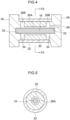
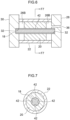
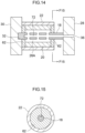
- Fig. 6 is a cross-section of a state in a resin filling process in a rotor manufacturing method according to a second exemplary embodiment of the present disclosure
- Fig. 7 illustrates cross-section of a section taken along line F7-F7 of Fig. 6
- Fig. 8 illustrates a cross-section of a rotor 40 manufactured by a rotor manufacturing method according to the second exemplary embodiment of the present disclosure.
- the outer diameter dimension of the rotor shaft 18 is set to the same as an inner diameter dimension of the permanent magnet 20 or to slightly smaller than the inner diameter dimension of the permanent magnet 20.
- Grooves 42 extending along the axial direction is formed at the outer periphery of the rotor shaft 18.
- the resin 24 is filled in liquid form between the rotor shaft 18 and the permanent magnet 20 through the grooves 42.
- the permanent magnet 20 is broken by the charging pressure of the resin 24 and the magnet reinforcement pipe 22 is expanded in diameter.
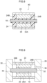
- Fig. 9 illustrates a cross-section of a state in a resin filling process in a rotor manufacturing method according to a third exemplary embodiment of the present disclosure.
- Fig. 10 illustrates a cross-section of a rotor 50 manufactured by the rotor manufacturing method according to the third exemplary embodiment.
- a collar-shaped collar portion 52 is formed at part of the outer periphery of the rotor shaft 18.
- the permanent magnet 20 and the rotor shaft 18 are disposed coaxially by an outer peripheral face of the collar portion 52 engaging (contacting) the inner peripheral face of the permanent magnet 20, and a gap 26A is formed for filling the resin 24 in liquid form between the rotor shaft 18 and the permanent magnet 20.
- the permanent magnet 20 is broken by the charging pressure of the high pressure resin 24 being filled in the gap 26A and the flange shaped gaps 26B, and the magnet reinforcement pipe 22 is expanded in diameter.
- configuration other than described above is similar to that of the first exemplary embodiment, and basically the same operation and advantageous effects are achieved to those of the first exemplary embodiment.
- the outer peripheral face of the collar portion 52 formed at part of the outer periphery of the rotor shaft 18 is engaged with the inner peripheral face of the permanent magnet 20, and the cylindrical shaped gap 26A is formed for filling the resin 24 in liquid form between the rotor shaft 18 and the permanent magnet 20. This means that there is no need for a positioning tool to achieve concentricity between the rotor shaft 18 and the permanent magnet 20.
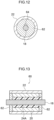
- Fig. 11 illustrates a cross-section of a state in a resin filling process of a rotor manufacturing method according to a fourth exemplary embodiment of the present disclosure
- Fig. 12 illustrates a cross-section of a section taken along line F12-F12 of Fig. 11
- Fig. 13 illustrates a cross-section of a configuration of a rotor 60 according to the fourth exemplary embodiment of the present disclosure.
- a pair of circular plate-shaped end rings 62 are arranged at the two axial direction sides with respect to the permanent magnet 20.
- a through hole 64 is formed at a center of the pair of end rings 62 for the rotor shaft 18 to pass through.
- An outer diameter dimension of the pair of end rings 62 is set as not less than the outer diameter dimension of the permanent magnet 20, and the outer peripheral faces of the pair of end rings 62 engage with the inner peripheral face of a magnet reinforcement pipe.
- a cylindrical shaped gap 26A is formed between the rotor shaft 18 and the permanent magnet 20.
- a resin-filling hole 64 in communication with the gap 26A is formed at least in one (only one in this case) of the pair of end rings 62.
- the resin 24 is filled in liquid form into the gap 26A through the resin-filling hole 64.
- the permanent magnet 20 is broken by the charging pressure of the resin 24, and the magnet reinforcement pipe 22 is expanded in diameter.
- the cylindrical shaped gap 26A can be formed for filling the resin 24 in liquid form between the rotor shaft 18 and the permanent magnet 20 while achieving concentricity between the rotor shaft 18 and the permanent magnet 20 using the pair of end rings 62.
- the resin 24 can be filled in liquid form into the gap 26A through the resin-filling hole 64 formed in one of the pair of end rings 62. In this exemplary embodiment too, there is no need for a positioning tool to achieve concentricity between the rotor shaft 18 and the permanent magnet 20.
- Fig. 14 is a cross-section illustrating a state in a resin filling process of a rotor manufacturing method according to a fifth exemplary embodiment of the present disclosure
- Fig. 15 is a cross-section illustrating a section taken along line F15-F15 of Fig. 14
- Fig. 16 illustrates a cross-section of a configuration of a rotor 70 according to the fifth exemplary embodiment of the present disclosure.
- a pair of circular plate-shaped end rings 62 is arranged at the two axial direction sides with respect to the permanent magnet 20, and a cylindrical shaped gap 26A is formed between the rotor shaft 18 and the permanent magnet 20.
- a resin-filling flow path 72 is formed in the rotor shaft 18 instead of the resin-filling hole 64 of the fourth exemplary embodiment.
- the resin-filling flow path 72 extends from one axial direction end face of the rotor shaft 18 to a portion on the other axial direction end side of the rotor shaft 18, and also branches toward the radial direction outside of the rotor shaft 18 at plural locations of an axial direction intermediate portion of the rotor shaft 18.
- the resin-filling flow path 72 opens onto plural locations on the outer peripheral face and onto one axial direction end face of the rotor shaft 18, and is in communication with the gap 26A.
- the one axial direction end face of the rotor shaft 18 is abutted against one mold, and the resin-filling gate 36 and the resin-filling flow path 72 are in communication with each other.
- the resin 24 is filled in liquid form through the resin-filling flow path 72 and into the gap 26A.
- the permanent magnet 20 is broken by the charging pressure of the resin 24, and the magnet reinforcement pipe 22 is expanded in diameter.
- the cylindrical shaped gap 26A can be formed for filling the resin 24 in liquid form between the rotor shaft 18 and the permanent magnet 20 while achieve concentricity between the rotor shaft 18 and the permanent magnet 20 using the pair of end rings 62.
- the resin 24 can be filled in liquid form into the gap 26A through the resin-filling flow path 72 formed in the rotor shaft 18. In this exemplary embodiment too, there is no need for a positioning tool to achieve concentricity between the rotor shaft 18 and the permanent magnet 20.
- Fig. 17 illustrates a cross-section of a configuration of a permanent magnet 20 provided to a rotor according to a sixth exemplary embodiment of the present disclosure.
- the rotor according to the present exemplary embodiment is configured basically the same as the rotor 12, the rotor 40, the rotor 50, the rotor 60, or the rotor 70 described above, however notches (indentations) 80 that serve as origin points when the permanent magnet 20 breaks are formed along the axial direction of the permanent magnet 20 to the inner peripheral face of the permanent magnet 20 before the resin 24 is filled between the rotor shaft 18 and the permanent magnet 20.
- notches (indentations) 80 that serve as origin points when the permanent magnet 20 breaks are formed along the axial direction of the permanent magnet 20 to the inner peripheral face of the permanent magnet 20 before the resin 24 is filled between the rotor shaft 18 and the permanent magnet 20.
- each of the notches 80 is, for example, formed with a triangular profile having an apex facing toward the radial direction outside of the permanent magnet 20 when viewed along the axial direction of the permanent magnet 20.
- the permanent magnet 20 breaks about origin points of each of the notches 80 when the resin 24 is filled between the rotor shaft 18 and the permanent magnet 20. This enables the permanent magnet 20 to be broken in a pre-set manner.
Landscapes
- Engineering & Computer Science (AREA)
- Power Engineering (AREA)
- Manufacturing & Machinery (AREA)
- Permanent Field Magnets Of Synchronous Machinery (AREA)
Applications Claiming Priority (2)
| Application Number | Priority Date | Filing Date | Title |
|---|---|---|---|
| JP2021171115 | 2021-10-19 | ||
| PCT/JP2022/027169 WO2023067858A1 (ja) | 2021-10-19 | 2022-07-08 | ロータの製造方法、ロータ及び回転電機 |
Publications (2)
| Publication Number | Publication Date |
|---|---|
| EP4404444A1 true EP4404444A1 (de) | 2024-07-24 |
| EP4404444A4 EP4404444A4 (de) | 2025-01-22 |
Family
ID=86058996
Family Applications (1)
| Application Number | Title | Priority Date | Filing Date |
|---|---|---|---|
| EP22883170.7A Pending EP4404444A4 (de) | 2021-10-19 | 2022-07-08 | Rotorherstellungsverfahren, rotor und elektrische drehmaschine |
Country Status (5)
| Country | Link |
|---|---|
| US (1) | US20240421679A1 (de) |
| EP (1) | EP4404444A4 (de) |
| JP (2) | JP7796136B2 (de) |
| CN (1) | CN118104112A (de) |
| WO (1) | WO2023067858A1 (de) |
Family Cites Families (13)
| Publication number | Priority date | Publication date | Assignee | Title |
|---|---|---|---|---|
| JPS4832242Y1 (de) * | 1970-02-13 | 1973-10-02 | ||
| JPH0491644A (ja) * | 1990-08-06 | 1992-03-25 | Hitachi Ltd | 超高速回転電機の永久磁石回転子、永久磁石回転子のバランス調整法 |
| JPH10210690A (ja) * | 1997-01-21 | 1998-08-07 | Isuzu Ceramics Kenkyusho:Kk | 発電機におけるロータの構造 |
| JPH11146609A (ja) * | 1997-11-07 | 1999-05-28 | Hitachi Ltd | 永久磁石回転子の製造法 |
| DK1223662T3 (da) * | 2001-01-15 | 2004-07-05 | Atlas Copco Airpower Nv | Fremgangsmåde til fremstilling af en permanentmagnetiseret rotor til en elektrisk höjhastighedsmotor |
| JP2005312250A (ja) | 2004-04-26 | 2005-11-04 | Meidensha Corp | 永久磁石式回転電機の磁石固定方法 |
| JP2009284720A (ja) * | 2008-05-26 | 2009-12-03 | Yaskawa Electric Corp | 永久磁石形同期電動機 |
| JP5298905B2 (ja) * | 2009-02-09 | 2013-09-25 | 日産自動車株式会社 | 分割永久磁石の製造方法とその分割永久磁石を用いた電動機 |
| US9350219B2 (en) * | 2011-02-14 | 2016-05-24 | Toyota Jidosha Kabushiki Kaisha | Rotor magnet, rotor, and rotor manufacturing method |
| JP2013116002A (ja) * | 2011-11-30 | 2013-06-10 | Mitsui High Tec Inc | 回転子に使用する永久磁石の分断方法 |
| JP6747965B2 (ja) * | 2016-12-22 | 2020-08-26 | ファナック株式会社 | 回転電機の回転軸部に固定される回転子部材、回転子、回転電機、および回転子を分解する方法 |
| JP7185311B2 (ja) | 2020-04-20 | 2022-12-07 | 株式会社ニューギン | 遊技機 |
| JP7448027B2 (ja) * | 2020-09-30 | 2024-03-12 | 株式会社Ihi | モーターロータ及びモーターロータの製造方法 |
-
2022
- 2022-07-08 EP EP22883170.7A patent/EP4404444A4/de active Pending
- 2022-07-08 US US18/701,163 patent/US20240421679A1/en active Pending
- 2022-07-08 WO PCT/JP2022/027169 patent/WO2023067858A1/ja not_active Ceased
- 2022-07-08 JP JP2023554263A patent/JP7796136B2/ja active Active
- 2022-07-08 CN CN202280068708.3A patent/CN118104112A/zh active Pending
-
2025
- 2025-11-06 JP JP2025187311A patent/JP2026009378A/ja active Pending
Also Published As
| Publication number | Publication date |
|---|---|
| WO2023067858A1 (ja) | 2023-04-27 |
| JPWO2023067858A1 (de) | 2023-04-27 |
| US20240421679A1 (en) | 2024-12-19 |
| JP7796136B2 (ja) | 2026-01-08 |
| EP4404444A4 (de) | 2025-01-22 |
| JP2026009378A (ja) | 2026-01-19 |
| CN118104112A (zh) | 2024-05-28 |
Similar Documents
| Publication | Publication Date | Title |
|---|---|---|
| EP2573917B1 (de) | Verfahren zur Herstellung eines Rotors und eines bürstenlosen Innenrotormotors | |
| US10530227B2 (en) | Manufacturing method of rotor core, manufacturing method of rotor, rotor and motor | |
| US20080024018A1 (en) | Rotor for an electric rotary machine, and a method of manufacture | |
| US10439460B2 (en) | Rotor of electric motor and its manufacturing method | |
| KR20040111596A (ko) | 세그먼트된 스테이터의 내주면을 실링하는 방법 및 전기기계 | |
| EP2124316A1 (de) | Rotor für eine elektrische pumpe und elektrische pumpe | |
| US9893573B2 (en) | Rotor of motor and such motor | |
| JP6026000B2 (ja) | 電動機の回転子、電動機、及び空気調和機 | |
| WO2017175534A1 (ja) | 永久磁石式回転電機の回転子 | |
| US20200185989A1 (en) | Rotor of synchronous motor with reinforcement member for pressing magnet | |
| KR102349405B1 (ko) | 본드 자석을 이용한 회전자 및 그를 포함하는 모터 | |
| EP4404444A1 (de) | Rotorherstellungsverfahren, rotor und elektrische drehmaschine | |
| EP3477830A1 (de) | Rotor und elektrische drehmaschine | |
| US20190123625A1 (en) | Rotor and production method therefor | |
| JP2024147838A (ja) | 磁極片部材及び磁気変調ギヤ | |
| EP0586710A1 (de) | Radial anisotropische, zylindrische magnete vom ferrite-typ, deren herstellungsmethoden und motoren. | |
| US20060152094A1 (en) | Rotor for micro-servomotor, and micro-servomotor equipped with said rotor | |
| JPH05260706A (ja) | 回転電機における永久磁石内蔵型回転子の製造方法 | |
| JP7448027B2 (ja) | モーターロータ及びモーターロータの製造方法 | |
| KR20040065530A (ko) | 회전자 | |
| JP6155574B2 (ja) | 永久磁石電動機、ロータ構造体、および、ロータ構造体の製造方法 | |
| CN113675972B (zh) | 马达的转子及其制造方法 | |
| EP2747248B1 (de) | Magnetrotoreinheit | |
| CN223451704U (zh) | 用于无刷电机的转子以及包括该转子的无刷电机 | |
| US11264863B2 (en) | Rotor of an electric machine and method for producing same |
Legal Events
| Date | Code | Title | Description |
|---|---|---|---|
| STAA | Information on the status of an ep patent application or granted ep patent |
Free format text: STATUS: THE INTERNATIONAL PUBLICATION HAS BEEN MADE |
|
| PUAI | Public reference made under article 153(3) epc to a published international application that has entered the european phase |
Free format text: ORIGINAL CODE: 0009012 |
|
| STAA | Information on the status of an ep patent application or granted ep patent |
Free format text: STATUS: REQUEST FOR EXAMINATION WAS MADE |
|
| 17P | Request for examination filed |
Effective date: 20240415 |
|
| AK | Designated contracting states |
Kind code of ref document: A1 Designated state(s): AL AT BE BG CH CY CZ DE DK EE ES FI FR GB GR HR HU IE IS IT LI LT LU LV MC MK MT NL NO PL PT RO RS SE SI SK SM TR |
|
| A4 | Supplementary search report drawn up and despatched |
Effective date: 20241220 |
|
| DAV | Request for validation of the european patent (deleted) | ||
| DAX | Request for extension of the european patent (deleted) | ||
| RIC1 | Information provided on ipc code assigned before grant |
Ipc: H02K 15/12 20060101ALI20241216BHEP Ipc: H02K 1/2733 20220101ALI20241216BHEP Ipc: H02K 15/03 20060101AFI20241216BHEP |