EP4404233A1 - Smd-sicherung mit vorgeformtem schirm - Google Patents
Smd-sicherung mit vorgeformtem schirm Download PDFInfo
- Publication number
- EP4404233A1 EP4404233A1 EP24152556.7A EP24152556A EP4404233A1 EP 4404233 A1 EP4404233 A1 EP 4404233A1 EP 24152556 A EP24152556 A EP 24152556A EP 4404233 A1 EP4404233 A1 EP 4404233A1
- Authority
- EP
- European Patent Office
- Prior art keywords
- fuse
- shield
- cylindrical
- cap cover
- stop region
- Prior art date
- Legal status (The legal status is an assumption and is not a legal conclusion. Google has not performed a legal analysis and makes no representation as to the accuracy of the status listed.)
- Granted
Links
Images




Classifications
-
- H—ELECTRICITY
- H01—ELECTRIC ELEMENTS
- H01H—ELECTRIC SWITCHES; RELAYS; SELECTORS; EMERGENCY PROTECTIVE DEVICES
- H01H85/00—Protective devices in which the current flows through a part of fusible material and this current is interrupted by displacement of the fusible material when this current becomes excessive
- H01H85/02—Details
- H01H85/04—Fuses, i.e. expendable parts of the protective device, e.g. cartridges
- H01H85/05—Component parts thereof
- H01H85/165—Casings
- H01H85/175—Casings characterised by the casing shape or form
-
- H—ELECTRICITY
- H01—ELECTRIC ELEMENTS
- H01H—ELECTRIC SWITCHES; RELAYS; SELECTORS; EMERGENCY PROTECTIVE DEVICES
- H01H85/00—Protective devices in which the current flows through a part of fusible material and this current is interrupted by displacement of the fusible material when this current becomes excessive
- H01H85/02—Details
- H01H85/04—Fuses, i.e. expendable parts of the protective device, e.g. cartridges
- H01H85/05—Component parts thereof
- H01H85/165—Casings
- H01H85/175—Casings characterised by the casing shape or form
- H01H85/1755—Casings characterised by the casing shape or form composite casing
-
- H—ELECTRICITY
- H01—ELECTRIC ELEMENTS
- H01H—ELECTRIC SWITCHES; RELAYS; SELECTORS; EMERGENCY PROTECTIVE DEVICES
- H01H85/00—Protective devices in which the current flows through a part of fusible material and this current is interrupted by displacement of the fusible material when this current becomes excessive
- H01H85/02—Details
- H01H85/04—Fuses, i.e. expendable parts of the protective device, e.g. cartridges
- H01H85/05—Component parts thereof
- H01H85/165—Casings
-
- H—ELECTRICITY
- H01—ELECTRIC ELEMENTS
- H01H—ELECTRIC SWITCHES; RELAYS; SELECTORS; EMERGENCY PROTECTIVE DEVICES
- H01H69/00—Apparatus or processes for the manufacture of emergency protective devices
- H01H69/02—Manufacture of fuses
-
- H—ELECTRICITY
- H01—ELECTRIC ELEMENTS
- H01H—ELECTRIC SWITCHES; RELAYS; SELECTORS; EMERGENCY PROTECTIVE DEVICES
- H01H85/00—Protective devices in which the current flows through a part of fusible material and this current is interrupted by displacement of the fusible material when this current becomes excessive
- H01H85/02—Details
- H01H85/04—Fuses, i.e. expendable parts of the protective device, e.g. cartridges
- H01H85/041—Fuses, i.e. expendable parts of the protective device, e.g. cartridges characterised by the type
- H01H85/0411—Miniature fuses
- H01H2085/0412—Miniature fuses specially adapted for being mounted on a printed circuit board
-
- H—ELECTRICITY
- H01—ELECTRIC ELEMENTS
- H01H—ELECTRIC SWITCHES; RELAYS; SELECTORS; EMERGENCY PROTECTIVE DEVICES
- H01H85/00—Protective devices in which the current flows through a part of fusible material and this current is interrupted by displacement of the fusible material when this current becomes excessive
- H01H85/02—Details
- H01H85/04—Fuses, i.e. expendable parts of the protective device, e.g. cartridges
- H01H85/041—Fuses, i.e. expendable parts of the protective device, e.g. cartridges characterised by the type
- H01H85/044—General constructions or structure of low voltage fuses, i.e. below 1000 V, or of fuses where the applicable voltage is not specified
- H01H85/045—General constructions or structure of low voltage fuses, i.e. below 1000 V, or of fuses where the applicable voltage is not specified cartridge type
- H01H85/0458—General constructions or structure of low voltage fuses, i.e. below 1000 V, or of fuses where the applicable voltage is not specified cartridge type with ferrule type end contacts
-
- H—ELECTRICITY
- H01—ELECTRIC ELEMENTS
- H01H—ELECTRIC SWITCHES; RELAYS; SELECTORS; EMERGENCY PROTECTIVE DEVICES
- H01H85/00—Protective devices in which the current flows through a part of fusible material and this current is interrupted by displacement of the fusible material when this current becomes excessive
- H01H85/02—Details
- H01H85/04—Fuses, i.e. expendable parts of the protective device, e.g. cartridges
- H01H85/05—Component parts thereof
- H01H85/143—Electrical contacts; Fastening fusible members to such contacts
Definitions
- Embodiments of the present disclosure relate to surface mount fuses and, more particularly, to surface mount fuses that are suitable for pick-and-place automation assembly.
- Fuses are current-sensitive devices that are designed as the intentional weak link in an electric circuit.
- fuses consist of a fusible element (the intentional weak link) disposed between two terminals, where the fusible element is contained in a housing.
- the function of the fuse is to provide discrete component or complete circuit protection by reliably melting under overcurrent conditions and thus safely interrupting the flow of current.
- a fuse may be selected based on its shape. Fuses may have axial leads for through-hole attachment to a printed circuit board (PCB) or may be leadless for surface mount attachment. Even within these two categories, a vast array of fuse shapes and sizes exist for different applications.
- PCB printed circuit board
- One type of surface mount fuse cylindrical features a cylindrical housing disposed between a pair of cylindrical cap terminals.
- pick-and-place One automation technique used in populating PCBs is known as pick-and-place.
- Components such as resistors, capacitors, integrated circuits, and fuses are placed on a tape-and-reel spool.
- the pick-and-place machine retrieves the components, one by one, from the spool, and places them on the PCB in the intended location. In other operations, the components are located, not on a spool, but on a surface for retrieval by the pick-and-placed machine. Because cylindrical fuses tend to roll when placed on a flat surface, they are not suitable for pick-and-place assembly operations. Further, industry tends to shrink the PCB board design to achieve space savings. The ability to orient other devices on the PCB with respect to the fuse is challenged when the fuse rolls freely, and may result in possible shorting during assembly
- An exemplary embodiment of a fuse shield in accordance with the present disclosure may include a shield adapted to partially surround a cylindrical fuse.
- the fuse shield includes a cylindrical body, a first cap cover, a second cap cover, and a stop region.
- the cylindrical cover is adapted to be placed over and partially surround a cylindrical fuse.
- the first cap cover is located on one side of the cylindrical body and the second cap cover is located on the other, opposite side of the cylindrical body.
- the stop region is located on an edge of the first cap cover to limit rotation of the cylindrical fuse to a first degree in one direction on a flat surface.
- An exemplary embodiment of shield for use with a round body fuse in accordance with the present disclosure may include a cylindrical body, a first cap, and a second cap.
- the cylindrical body partially surrounds a housing of the round body fuse.
- the first cap is adapted to partially surrounds a first terminal of the round body fuse and is adjacent the cylindrical body at a first end.
- the second cap is adapted to partially surrounds a second terminal of the round body fuse and is adjacent the cylindrical body at a second, opposite end.
- An exemplary embodiment of a method to attach a pre-molded shield to a cylindrical fuse in accordance with the present disclosure may include positioning and pushing operations.
- the pre-molded shield is pushed over the cylindrical fuse, where the pre-molded shield includes two cap covers located between a body, the first cap cover being adjacent one end cap of the cylindrical fuse and the other cap cover being adjacent the other end cap.
- the pre-molded shield is then pushed over the cylindrical fuse, with stop regions of the pre-molded shield being on either side and a first distance apart. The stop regions separate to being a second distance apart during the pushing operation.
- a surface mount device cylindrical fuse is disclosed with a pre-molded shield.
- the pre-molded shield covers a portion of the cylindrical housing of the cylindrical fuse as well as some of its end caps (terminals). Flexible enough to snap over the cylindrical fuse, the pre-molded shield has a top flat surface to facilitate retrieval of the shielded cylindrical fuse during pick-and-place automation operations.
- the bottom portion of the pre-molded shield is also planar and limits rotation of the cylindrical fuse on a flat surface, which also facilitates pick-and-place automation.
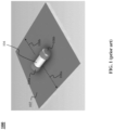
- FIG. 1 is a representative drawing of a cylindrical fuse 100, according to the prior art.
- the cylindrical fuse 100 is disposed on a flat surface 102, such as a printed circuit board (PCB).
- the cylindrical fuse 100 includes a body 104 inside which a fusible element is disposed (not shown), and two end caps (terminals) 106a-106b (collectively, "end caps 106").
- the body 104 is cylindrical, and thus can roll on the flat or even on a nearly flat surface 102.
- the end caps 106 are cylindrical where they join the body, resulting in a longer cylindrical shape for the cylindrical fuse 100.
- the cylindrical fuse 100 is a type of surface mount device (SMD) in which the end caps 106, as the terminals of the fuse, are soldered onto pads of a PCB.
- SMD surface mount device
- the cylindrical fuse 100 is capable of and likely to roll on an axis orthogonal to the body 104.
- the cylindrical fuse 100 may rotate in a first direction 108a or a second direction 108b, as the two directions constitute an axis orthogonal to the body 104 of the cylindrical fuse. Put another way, the first direction 108a is 180° from the second direction 108b.
- the cylindrical fuse 100 may rotate more than 360°, that is, in at least a complete rotation around the body 104 in either direction 108a or 108b.
- the cylindrical fuse 100 may rotate multiple times. Left unattended, the cylindrical fuse 100 may rotate, in either direction 108a or 108b, eventually falling off the flat surface 102.
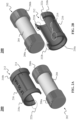
- FIGs. 2A-2B are representative drawings of a fuse assembly consisting of a cylindrical fuse with a pre-molded shield 200 (hereinafter, "shielded cylindrical fuse 200"), according to exemplary embodiments.
- FIG. 2A is an exploded perspective top view
- FIG. 2B is an exploded perspective bottom view of the shielded cylindrical fuse 200.
- the shielded cylindrical fuse 200 is made up of a cylindrical fuse 202 and a pre-molded shield 212 suitable for attaching to and substantially surrounding the cylindrical fuse.
- the cylindrical fuse 202 includes a body 204 which is cylindrical and two end caps (terminals) 206a-b (collectively, "end caps 206"), with one end cap 206a being disposed at one end of the body 204 and the other end cap 206 being disposed at a second, opposite end of the body.
- the body 204 constitutes a housing of the fusible element (not shown) of the cylindrical fuse 202.
- the cylindrical fuse 202 is a SMD round body fuse in which the end caps 206, as the terminals of the fuse, are soldered onto pads of a PCB.
- the pre-molded shield 212 consists of a body 214, a flat portion 216, and two cap covers 218a and 218b (collectively, "cap covers 218").
- the cap covers 218 are disposed on either end of the body 214, with cap cover 218a being at a first end of the pre-molded shield 212 and also adjacent a first side of the body 214, and the cap cover 218b being adjacent a second, opposite side of the body 214.
- the flat portion 216 is a portion of the pre-molded shield 212 that is planar. In exemplary embodiments, the flat portion 216 is equidistant a first edge and a second edge of the cylindrical body 214. In some embodiments, the flat portion 216 does not occupy either of the cap covers 218 but is instead sandwiched between cap cover 218a and 218b.
- the cap covers 218 and the body 214 of the pre-molded shield 212 are all cylindrical in shape.
- the pre-molded shield 212 substantially surrounds and covers the cylindrical fuse 202 but does not completely surround and cover the cylindrical fuse.
- the pre-molded shield 212 surrounds and circumferentially covers more than half the cylindrical fuse 202.
- the pre-molded shield 212 circumferentially covers between 65% (234°) and 85% (306°) of the cylindrical fuse 202.
- the pre-molded shield 212 circumferentially covers approximately 75% (270°) of the cylindrical fuse 202.
- the pre-molded shield 212 also partially covers the end caps 206 of the cylindrical fuse.
- the cap covers 218 of the pre-molded shield 212 are sized to fit over the end cap portions 208.
- the cap covers 218 of the pre-molded shield 212 have a slightly larger diameter than that of the body 214.
- the pre-molded shield 212 further includes stop regions 222a-d (collectively, "stop regions 222").
- the stop regions 222 are the portion of the pre-molded shield 212 that limit the rotational movement of the cylindrical fuse 202 on a flat surface once the pre-molded shield is placed over the cylindrical fuse.
- the flat portion 216 is located opposite the stop regions 222 and is equidistant therebetween.
- limit rotation is defined herein to mean that the cylindrical fuse 202 is prevented from rotating as it would be able to without the pre-molded shield 212.
- to limit rotation of the cylindrical fuse 202 means the cylindrical fuse cannot rotate more than 126° around its circumference, due to having a pre-molded shield 212 that surrounds 65% of the cylindrical fuse, which is equivalent to limiting its movement to no more than 63° in one direction.
- to limit rotation of the cylindrical fuse 202 means the cylindrical fuse cannot rotate more than 90° around its circumference, due to having a pre-molded shield 212 that surrounds 75% of the cylindrical fuse, which is equivalent to limiting its movement to no more than 45° in one direction.
- to limit rotation of the cylindrical fuse 202 means the cylindrical fuse cannot rotate more than 54° around its circumference, due to having a pre-molded shield 212 that surrounds 85% of the cylindrical fuse, which is equivalent to limiting its movement to no more than 27° in one direction.
- the stop regions 222 are disposed on the two edges of each cap cover 218. Since the pre-molded shield 212 does not fully surround the cylindrical fuse 202, the body 214 and cap cover 218 each have two edges at opposite ends of the open cylindrical structure of the pre-molded shield.
- stop region 222a is disposed at first edge of cap cover 218a while stop region 222b is disposed at a second edge of cap cover 218a.
- stop region 222a is on one side of the open cylindrical structure whereas stop region 222b is at the second, opposite side of the open cylindrical structure, and both stop region 222a and 222b are part of the same cap cover 218a.
- Stop region 222c is disposed at a first edge of cap cover 218b while stop region 222d is disposed at a second edge of cap cover 218b.
- stop region 222c is on one side of the open cylindrical structure whereas stop region 222d is at the second, opposite side of the open cylindrical structure, and both stop region 222c and 222d are part of the same cap cover 218b.
- assembly of the cylindrical fuse 202 is completed before the pre-molded shield 212 is added thereon.
- the two end caps 206 are added to either side of the body 204, which houses the fusible element.
- the pre-molded shield 212 is affixed to the cylindrical fuse 202.
- the pre-molded shield 212 is somewhat flexible, and expands slightly at the open end (including the stop regions 222) to enable the pre-molded shield to be pushed onto the cylindrical fuse 202.
- the pre-molded shield 212 conforms back to its original shape, thus forming a tight coupling to the cylindrical fuse, without need of adhesive.
- the pre-molded shield 212 is not thereafter removed from the cylindrical fuse 202, as the shielded cylindrical fuse 200 functions as intended with the pre-molded shield thereon.
- FIG. 3 is a representative drawing of the pre-molded shield 212 to be attached to the cylindrical fuse 202 and forming the shielded cylindrical fuse 200 of FIGs. 2A-2B , according to exemplary embodiments.
- the stop regions 222 are clearly shown.
- the bottom of the pre-molded shield 212 form a second flat surface (besides the flat portion 216), as indicated by a plane 302 (dashed lines).
- Body ends 304a and 304b are also in the plane 302 and are thus planar to the stop regions 222.
- the body ends 304 may thus also be thought of as "stop regions”.
- the stop regions 222 and body ends 304 in the plane 302 control the rotation of the shielded cylindrical fuse 200 on a flat surface.
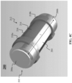
- FIGs. 4A-4C are representative drawings of the shielded cylindrical fuse 200 of FIGs. 2A-2B , according to exemplary embodiments.
- FIG. 4A is a top perspective view
- FIG. 4B is a side view
- FIG. 4C is a bottom perspective view of the shielded cylindrical fuse 200.
- the flat portion 216 of the pre-molded shield 212 has a height, h.
- the flat portion 216 simplifies the labeling of the shielded cylindrical fuse 200, as labels print more easily on flat surfaces (as compared to cylindrical surfaces).
- the cylindrical shape of the cylindrical fuse 100 poses handling difficulties such as rolling and potential displacement during board mounting.
- the flat portion 216 in addition to providing a surface for marking, the flat portion 216 enables the pick-and-place device to grip the shielded cylindrical fuse 200.
- the height, h is selected to accommodate the characteristics of the pick-and-place machinery, where the height, h , is sufficient for the pick-and-place machinery to grab, grip, clasp, or otherwise retrieve the shielded cylindrical fuse 200 from a surface.
- the pre-molded shield 212 can also facilitate the marking of the cylindrical fuse 202 to facilitate pick-and-place applications. The pre-molded shield 212 thus enables the shielded cylindrical fuse 200 to be used in high-speed pick-and-place applications.
- the pre-molded shield 212 is made as a unitary structure using a mold, including but not limited to injection molded plastic, thermoform, and so on.
- the cap covers 218 of the pre-molded shield 212 have a circumference that is slightly larger than that of the body 214.
- the body 214 of the pre-molded shield 212 has a diameter, d 1
- the cap covers 218 have a diameter, d 2 , where d 1 ⁇ d 2 .
- the diameter, d 2 , of the cap covers 218 is interference fit to the diameter, d 1 , of the body plus the height, h, of the flat portion 216, as shown in FIG.
- the body 204 of the cylindrical fuse 202 has a diameter that is interference fit to the diameter, d 1 and the end caps 206 have a diameter that is interference fit to the diameter, d 2 .
- the cap covers 218 of the pre-molded shield 212 cover a portion of the end caps 206, in some embodiments.
- the size of the cap covers 218 may vary, depending on how much of the end caps 206 are to be covered.
- FIGs. 5A-5C are representative drawings of the shielded cylindrical fuse 200, according to exemplary embodiments.
- the side views of the cylindrical fuse 200 are shown in a first position ( FIG. 5A ), a second position ( FIG. 5B ), and a third position ( FIG. 5C ).
- the plane 302 (thick dashed lines) from FIG. 3 as well as a flat surface, s (thin dashed lines) are shown.
- the pre-molded shield 212 of the shielded cylindrical fuse 200 controls the amount of rotation on the flat surface, s, that will occur. In exemplary embodiments, with the pre-molded shield 212, the cylindrical fuse 202 will not rotate 360°, as does the prior art cylindrical fuse 100 ( FIG. 1 ).
- the circumferential coverage of the pre-molded shield 212 on the cylindrical fuse 202 is adjustable, based on how much control over movement of the shielded cylindrical fuse 200 is desired. For example, assume that the shielded cylindrical fuse 200 in FIGs. 5A-5C rolls x inches on the flat surface, s, and the pre-molded shield 212 covers 75% (270°) of the cylindrical fuse 202. If the environment calls for the shielded cylindrical fuse 200 to roll y inches, where y ⁇ x , then the pre-molded shield 212 may be designed to cover 85% (306°) of the cylindrical fuse 202. By having the stop regions 222 lower on the cylindrical fuse 102, such as at locations 502a and 502b in FIG.
- the shielded cylindrical fuse 200 will rotate less, thus moving y inches. Or if the environment enables the shielded cylindrical fuse 200 to roll z inches, where z > x , then the pre-molded shield 212 may be designed to cover 65% (234°) of the cylindrical fuse 202. By having the stop regions 222 higher on the cylindrical fuse 102, such as at locations 504a and 504b in FIG. 5A , the shielded cylindrical fuse 200 will rotate more, thus moving z inches.
- FIGs. 6 and 7 are representative tables 600 and 700 showing results of empirical tests performed on the shielded cylindrical fuse 200, according to exemplary embodiments. Since the pre-molded shield 212 is designed to be permanently coupled with the cylindrical fuse 202, the tests were run to ensure that the cylindrical fuse 202 operates as designed. In Table 600, the resistance and blow time were measured for ten fuses experiencing a 300% current overload, which is enough to cause the fuses to break. A maximum resistance of 11.415 ohms and a maximum blow time of 0.012 seconds were noted, which is well within the specification for the cylindrical fuse.
- Table 700 pre- and post-run resistances were measured so that a resistance shift could be measured. A maximum resistance shift of 2.96% was recorded, which is also within specification for the cylindrical fuse.
- the right side of Table 700 shows that the ten fuses were subjected to a life test in which 110% current was issued for four hours, where 110% is not enough to break the fuse. All fuses were able to survive the four-hour life test, with a maximum resistance shift of only 2.96%.
- the results of Tables 600 and 700 are consistent with measurements taken of similar cylindrical fuses without the pre-molded shield.
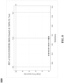
- FIG. 8 is a representative graph 800 of the tests performed on the shielded cylindrical fuse, according to exemplary embodiments.
- the graph 800 is a plot of the data in Table 600, with the dots at the bottom showing the blow times for each fuse. Tables 600 and 700 and the graph 800 show that the cylindrical fuse is not negatively impacted from having the pre-molded shield thereon.
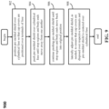
- FIG. 9 is a flow diagram 900 of a method of attaching the pre-molded 212 to a cylindrical fuse, such as the cylindrical fuse 202 of FIGs. 2A-2B , according to exemplary embodiments.
- the pre-molded shield 212 is made of a flexible material that bends at its end region, namely, where the stop regions 222 and body ends 304 are located.
- the pre-molded shield 212 is first positioned over the cylindrical fuse 202 so that the cap covers 218 are positioned over the end caps (terminals) 206 of the cylindrical fuse (block 902). Stop regions 222a and 222b, 222c and 222d, and body ends 304a and 304b are a first distance from one another.
- the pre-molded shield 212 is next pushed over the cylindrical fuse 202 until the stop regions 222 and body ends 304 move away from one another (block 902), due to the flexibility of the pre-molded shield 212. More particularly, stop regions 222a and 222b move apart from one another, similarly, stop regions 222c and 222d move apart from one another, and body ends 304a and 304b move apart from one another, until they are all a second distance from one another, the second distance being greater than the first distance. This is due to the fact that the stop regions 222a and 222b, stop regions 222c and 222d, and body ends 304a and 304b, when at the first distance from one another in their resting state, the first distance is smaller than the diameter of the cylindrical fuse 202.
- the pre-molded shield 212 is further pushed so that respective opposing stop regions and body ends move back to their original position (block 906).
- the stop regions 222 and body ends 304 are disposed more than halfway over the cylindrical fuse 202, where the halfway point of the fuse is where the dimension of the fuse is greatest (its diameter). Because the dimension of the cylindrical fuse 202 gets smaller as the pre-molded shield 212 passes the halfway point, the opposing stop regions 222 and body ends 304 return to their original position.
- the pre-molded shield 212 is attached to the cylindrical fuse 202.
- Lateral adjustments to the pre-molded shield 212, now attached to the cylindrical fuse 202 may be made, in some embodiments, to ensure that the cap covers 218 are disposed over respective end caps 206 of the cylindrical fuse (block 908) and to ensure that the pre-molded shield is centered over the cylindrical fuse. Lateral adjustment is movement of the pre-molded shield 212 left or right along the axis of the cylindrical fuse 202, as shown by the arrow, l , in FIG. 4C .
Landscapes
- Chemical & Material Sciences (AREA)
- Composite Materials (AREA)
- Engineering & Computer Science (AREA)
- Manufacturing & Machinery (AREA)
- Fuses (AREA)
Applications Claiming Priority (1)
| Application Number | Priority Date | Filing Date | Title |
|---|---|---|---|
| US18/099,012 US11942300B1 (en) | 2023-01-19 | 2023-01-19 | SMD fuse with pre-molded shield |
Publications (2)
| Publication Number | Publication Date |
|---|---|
| EP4404233A1 true EP4404233A1 (de) | 2024-07-24 |
| EP4404233B1 EP4404233B1 (de) | 2025-11-26 |
Family
ID=89661177
Family Applications (1)
| Application Number | Title | Priority Date | Filing Date |
|---|---|---|---|
| EP24152556.7A Active EP4404233B1 (de) | 2023-01-19 | 2024-01-18 | Smd-sicherung mit vorgeformtem schirm |
Country Status (3)
| Country | Link |
|---|---|
| US (1) | US11942300B1 (de) |
| EP (1) | EP4404233B1 (de) |
| CN (1) | CN118366829A (de) |
Citations (4)
| Publication number | Priority date | Publication date | Assignee | Title |
|---|---|---|---|---|
| US4755785A (en) * | 1987-01-29 | 1988-07-05 | Bel Fuse Inc. | Surface mounted fuse assembly |
| EP0307067A2 (de) * | 1987-09-11 | 1989-03-15 | International Control Automation Finance S.A. | Sicherungsabdeckungen |
| US4962363A (en) * | 1989-04-10 | 1990-10-09 | Littelfuse, Inc. | Surface mountable leadless fuse |
| US5982266A (en) * | 1998-09-29 | 1999-11-09 | Commonwealth Edison Company | Fuse block-out device |
Family Cites Families (9)
| Publication number | Priority date | Publication date | Assignee | Title |
|---|---|---|---|---|
| US3813626A (en) * | 1972-12-15 | 1974-05-28 | Robertshaw Controls Co | Fuse retainer and extractor |
| US4094212A (en) * | 1977-04-07 | 1978-06-13 | Fischer & Porter Company | Fuse-mate |
| US4473268A (en) * | 1982-01-26 | 1984-09-25 | Hitachi, Ltd. | Device for mounting cartridge fuse |
| US4926290A (en) * | 1987-09-11 | 1990-05-15 | The Babcock & Wilcox Company | Snap on fuse cover |
| IT221342Z2 (it) * | 1990-05-31 | 1994-03-04 | Fittings Ind Srl | Portafusibili perfezionato, in particolare per circuiti stampati. |
| KR100218960B1 (ko) * | 1997-02-26 | 1999-09-01 | 윤종용 | 전자렌지의 휴즈홀더 고정장치 |
| US20070093089A1 (en) * | 2005-10-20 | 2007-04-26 | Ford Douglas K | Relay-fuse system and method thereof |
| ITMI20070186A1 (it) * | 2007-02-05 | 2008-08-06 | Morsettitalia Spa | Procedimento per la produzione di elementi di contatto mobili a lamelle ed elementi di contatto attuati conn tale procedimento |
| KR102263504B1 (ko) * | 2017-11-27 | 2021-06-14 | 콘쿼 일렉트로닉스 캄파니, 리미티드 | 퓨즈의 퓨즈 와이어 고정 구조체 |
-
2023
- 2023-01-19 US US18/099,012 patent/US11942300B1/en active Active
-
2024
- 2024-01-18 EP EP24152556.7A patent/EP4404233B1/de active Active
- 2024-01-19 CN CN202410082017.XA patent/CN118366829A/zh active Pending
Patent Citations (4)
| Publication number | Priority date | Publication date | Assignee | Title |
|---|---|---|---|---|
| US4755785A (en) * | 1987-01-29 | 1988-07-05 | Bel Fuse Inc. | Surface mounted fuse assembly |
| EP0307067A2 (de) * | 1987-09-11 | 1989-03-15 | International Control Automation Finance S.A. | Sicherungsabdeckungen |
| US4962363A (en) * | 1989-04-10 | 1990-10-09 | Littelfuse, Inc. | Surface mountable leadless fuse |
| US5982266A (en) * | 1998-09-29 | 1999-11-09 | Commonwealth Edison Company | Fuse block-out device |
Also Published As
| Publication number | Publication date |
|---|---|
| US11942300B1 (en) | 2024-03-26 |
| CN118366829A (zh) | 2024-07-19 |
| EP4404233B1 (de) | 2025-11-26 |
Similar Documents
| Publication | Publication Date | Title |
|---|---|---|
| US6307462B2 (en) | Low profile mount for metal oxide varistor package with short circuit protection and method | |
| US4498047A (en) | Integrated circuit mounting apparatus | |
| JPH058914U (ja) | コイル部品 | |
| US20040099773A1 (en) | Wire retainer | |
| EP4404233A1 (de) | Smd-sicherung mit vorgeformtem schirm | |
| US4602122A (en) | Automatically-insertable case suitable for wire-wound magnetic cores | |
| US8475180B2 (en) | Conductive component | |
| EP4127631B1 (de) | Elektroanschlusseinrichtung und verfahren zur montage einer elektroanschlusseinrichtung | |
| EP2073355B1 (de) | Spulenkörper für einen motor | |
| US5726862A (en) | Electrical component having formed leads | |
| US20160336136A1 (en) | Integral complex safety apparatus | |
| KR20160134492A (ko) | 일체형 복합 안전장치 | |
| GB2585464A (en) | Aluminum alloy miniature cartridge fuses | |
| US3947800A (en) | Variable resistance control | |
| US4542439A (en) | Surface mount component | |
| KR19990036798A (ko) | 전자 릴레이와 전기 부품을 접속시키는 장치 및 방법 | |
| CN218337042U (zh) | 表面安装器件装配件 | |
| GB2377828A (en) | Twist lock connection system | |
| JPH02119201A (ja) | 表面取付型抵抗器とその製造方法 | |
| US3322995A (en) | Electronic component and method of manufacture thereof | |
| US7612294B2 (en) | Electrical component having a flat mounting surface | |
| JPH04359403A (ja) | 過電流過電圧保護素子及びそのホルダー | |
| US4949221A (en) | Encased electronic component | |
| EP4312242B1 (de) | Sicherungskörper mit gekerbten enden | |
| CN214588600U (zh) | 一种断路器的开距机构 |
Legal Events
| Date | Code | Title | Description |
|---|---|---|---|
| PUAI | Public reference made under article 153(3) epc to a published international application that has entered the european phase |
Free format text: ORIGINAL CODE: 0009012 |
|
| STAA | Information on the status of an ep patent application or granted ep patent |
Free format text: STATUS: THE APPLICATION HAS BEEN PUBLISHED |
|
| AK | Designated contracting states |
Kind code of ref document: A1 Designated state(s): AL AT BE BG CH CY CZ DE DK EE ES FI FR GB GR HR HU IE IS IT LI LT LU LV MC ME MK MT NL NO PL PT RO RS SE SI SK SM TR |
|
| STAA | Information on the status of an ep patent application or granted ep patent |
Free format text: STATUS: REQUEST FOR EXAMINATION WAS MADE |
|
| 17P | Request for examination filed |
Effective date: 20250122 |
|
| GRAP | Despatch of communication of intention to grant a patent |
Free format text: ORIGINAL CODE: EPIDOSNIGR1 |
|
| STAA | Information on the status of an ep patent application or granted ep patent |
Free format text: STATUS: GRANT OF PATENT IS INTENDED |
|
| INTG | Intention to grant announced |
Effective date: 20250616 |
|
| GRAS | Grant fee paid |
Free format text: ORIGINAL CODE: EPIDOSNIGR3 |
|
| GRAA | (expected) grant |
Free format text: ORIGINAL CODE: 0009210 |
|
| STAA | Information on the status of an ep patent application or granted ep patent |
Free format text: STATUS: THE PATENT HAS BEEN GRANTED |
|
| AK | Designated contracting states |
Kind code of ref document: B1 Designated state(s): AL AT BE BG CH CY CZ DE DK EE ES FI FR GB GR HR HU IE IS IT LI LT LU LV MC ME MK MT NL NO PL PT RO RS SE SI SK SM TR |
|
| REG | Reference to a national code |
Ref country code: CH Ref legal event code: F10 Free format text: ST27 STATUS EVENT CODE: U-0-0-F10-F00 (AS PROVIDED BY THE NATIONAL OFFICE) Effective date: 20251126 Ref country code: GB Ref legal event code: FG4D |
|
| P01 | Opt-out of the competence of the unified patent court (upc) registered |
Free format text: CASE NUMBER: UPC_APP_0011877_4404233/2025 Effective date: 20251031 |
|
| REG | Reference to a national code |
Ref country code: DE Ref legal event code: R096 Ref document number: 602024001346 Country of ref document: DE |
|
| REG | Reference to a national code |
Ref country code: IE Ref legal event code: FG4D |
|
| REG | Reference to a national code |
Ref country code: NL Ref legal event code: MP Effective date: 20251126 |
|
| PG25 | Lapsed in a contracting state [announced via postgrant information from national office to epo] |
Ref country code: ES Free format text: LAPSE BECAUSE OF FAILURE TO SUBMIT A TRANSLATION OF THE DESCRIPTION OR TO PAY THE FEE WITHIN THE PRESCRIBED TIME-LIMIT Effective date: 20251126 |
|
| REG | Reference to a national code |
Ref country code: LT Ref legal event code: MG9D |
|
| PG25 | Lapsed in a contracting state [announced via postgrant information from national office to epo] |
Ref country code: NO Free format text: LAPSE BECAUSE OF FAILURE TO SUBMIT A TRANSLATION OF THE DESCRIPTION OR TO PAY THE FEE WITHIN THE PRESCRIBED TIME-LIMIT Effective date: 20260226 |
|
| PGFP | Annual fee paid to national office [announced via postgrant information from national office to epo] |
Ref country code: DE Payment date: 20251216 Year of fee payment: 3 |
|
| PG25 | Lapsed in a contracting state [announced via postgrant information from national office to epo] |
Ref country code: FI Free format text: LAPSE BECAUSE OF FAILURE TO SUBMIT A TRANSLATION OF THE DESCRIPTION OR TO PAY THE FEE WITHIN THE PRESCRIBED TIME-LIMIT Effective date: 20251126 Ref country code: HR Free format text: LAPSE BECAUSE OF FAILURE TO SUBMIT A TRANSLATION OF THE DESCRIPTION OR TO PAY THE FEE WITHIN THE PRESCRIBED TIME-LIMIT Effective date: 20251126 Ref country code: AT Free format text: LAPSE BECAUSE OF FAILURE TO SUBMIT A TRANSLATION OF THE DESCRIPTION OR TO PAY THE FEE WITHIN THE PRESCRIBED TIME-LIMIT Effective date: 20251126 |
|
| PGFP | Annual fee paid to national office [announced via postgrant information from national office to epo] |
Ref country code: AT Payment date: 20260301 Year of fee payment: 3 |
|
| REG | Reference to a national code |
Ref country code: AT Ref legal event code: MK05 Ref document number: 1861965 Country of ref document: AT Kind code of ref document: T Effective date: 20251126 |
|
| PG25 | Lapsed in a contracting state [announced via postgrant information from national office to epo] |
Ref country code: NL Free format text: LAPSE BECAUSE OF FAILURE TO SUBMIT A TRANSLATION OF THE DESCRIPTION OR TO PAY THE FEE WITHIN THE PRESCRIBED TIME-LIMIT Effective date: 20251126 |
|
| PG25 | Lapsed in a contracting state [announced via postgrant information from national office to epo] |
Ref country code: RS Free format text: LAPSE BECAUSE OF FAILURE TO SUBMIT A TRANSLATION OF THE DESCRIPTION OR TO PAY THE FEE WITHIN THE PRESCRIBED TIME-LIMIT Effective date: 20260226 |
|
| PG25 | Lapsed in a contracting state [announced via postgrant information from national office to epo] |
Ref country code: IS Free format text: LAPSE BECAUSE OF FAILURE TO SUBMIT A TRANSLATION OF THE DESCRIPTION OR TO PAY THE FEE WITHIN THE PRESCRIBED TIME-LIMIT Effective date: 20260326 |
|
| PG25 | Lapsed in a contracting state [announced via postgrant information from national office to epo] |
Ref country code: PT Free format text: LAPSE BECAUSE OF FAILURE TO SUBMIT A TRANSLATION OF THE DESCRIPTION OR TO PAY THE FEE WITHIN THE PRESCRIBED TIME-LIMIT Effective date: 20260326 |
|
| PG25 | Lapsed in a contracting state [announced via postgrant information from national office to epo] |
Ref country code: PL Free format text: LAPSE BECAUSE OF FAILURE TO SUBMIT A TRANSLATION OF THE DESCRIPTION OR TO PAY THE FEE WITHIN THE PRESCRIBED TIME-LIMIT Effective date: 20251126 |
|
| PG25 | Lapsed in a contracting state [announced via postgrant information from national office to epo] |
Ref country code: LV Free format text: LAPSE BECAUSE OF FAILURE TO SUBMIT A TRANSLATION OF THE DESCRIPTION OR TO PAY THE FEE WITHIN THE PRESCRIBED TIME-LIMIT Effective date: 20251126 |