EP4404178A1 - Gate-on-array-treiberschaltung, anzeigetafel und anzeigevorrichtung - Google Patents
Gate-on-array-treiberschaltung, anzeigetafel und anzeigevorrichtung Download PDFInfo
- Publication number
- EP4404178A1 EP4404178A1 EP21941017.2A EP21941017A EP4404178A1 EP 4404178 A1 EP4404178 A1 EP 4404178A1 EP 21941017 A EP21941017 A EP 21941017A EP 4404178 A1 EP4404178 A1 EP 4404178A1
- Authority
- EP
- European Patent Office
- Prior art keywords
- signal
- circuit
- line scan
- electronic switch
- stage
- Prior art date
- Legal status (The legal status is an assumption and is not a legal conclusion. Google has not performed a legal analysis and makes no representation as to the accuracy of the status listed.)
- Pending
Links
Images


Classifications
-
- G—PHYSICS
- G09—EDUCATION; CRYPTOGRAPHY; DISPLAY; ADVERTISING; SEALS
- G09G—ARRANGEMENTS OR CIRCUITS FOR CONTROL OF INDICATING DEVICES USING STATIC MEANS TO PRESENT VARIABLE INFORMATION
- G09G3/00—Control arrangements or circuits, of interest only in connection with visual indicators other than cathode-ray tubes
- G09G3/20—Control arrangements or circuits, of interest only in connection with visual indicators other than cathode-ray tubes for presentation of an assembly of a number of characters, e.g. a page, by composing the assembly by combination of individual elements arranged in a matrix no fixed position being assigned to or needed to be assigned to the individual characters or partial characters
- G09G3/2092—Details of a display terminals using a flat panel, the details relating to the control arrangement of the display terminal and to the interfaces thereto
-
- G—PHYSICS
- G09—EDUCATION; CRYPTOGRAPHY; DISPLAY; ADVERTISING; SEALS
- G09G—ARRANGEMENTS OR CIRCUITS FOR CONTROL OF INDICATING DEVICES USING STATIC MEANS TO PRESENT VARIABLE INFORMATION
- G09G3/00—Control arrangements or circuits, of interest only in connection with visual indicators other than cathode-ray tubes
- G09G3/20—Control arrangements or circuits, of interest only in connection with visual indicators other than cathode-ray tubes for presentation of an assembly of a number of characters, e.g. a page, by composing the assembly by combination of individual elements arranged in a matrix no fixed position being assigned to or needed to be assigned to the individual characters or partial characters
- G09G3/22—Control arrangements or circuits, of interest only in connection with visual indicators other than cathode-ray tubes for presentation of an assembly of a number of characters, e.g. a page, by composing the assembly by combination of individual elements arranged in a matrix no fixed position being assigned to or needed to be assigned to the individual characters or partial characters using controlled light sources
- G09G3/30—Control arrangements or circuits, of interest only in connection with visual indicators other than cathode-ray tubes for presentation of an assembly of a number of characters, e.g. a page, by composing the assembly by combination of individual elements arranged in a matrix no fixed position being assigned to or needed to be assigned to the individual characters or partial characters using controlled light sources using electroluminescent panels
- G09G3/32—Control arrangements or circuits, of interest only in connection with visual indicators other than cathode-ray tubes for presentation of an assembly of a number of characters, e.g. a page, by composing the assembly by combination of individual elements arranged in a matrix no fixed position being assigned to or needed to be assigned to the individual characters or partial characters using controlled light sources using electroluminescent panels semiconductive, e.g. using light-emitting diodes [LED]
- G09G3/3208—Control arrangements or circuits, of interest only in connection with visual indicators other than cathode-ray tubes for presentation of an assembly of a number of characters, e.g. a page, by composing the assembly by combination of individual elements arranged in a matrix no fixed position being assigned to or needed to be assigned to the individual characters or partial characters using controlled light sources using electroluminescent panels semiconductive, e.g. using light-emitting diodes [LED] organic, e.g. using organic light-emitting diodes [OLED]
- G09G3/3266—Details of drivers for scan electrodes
-
- G—PHYSICS
- G09—EDUCATION; CRYPTOGRAPHY; DISPLAY; ADVERTISING; SEALS
- G09G—ARRANGEMENTS OR CIRCUITS FOR CONTROL OF INDICATING DEVICES USING STATIC MEANS TO PRESENT VARIABLE INFORMATION
- G09G3/00—Control arrangements or circuits, of interest only in connection with visual indicators other than cathode-ray tubes
- G09G3/20—Control arrangements or circuits, of interest only in connection with visual indicators other than cathode-ray tubes for presentation of an assembly of a number of characters, e.g. a page, by composing the assembly by combination of individual elements arranged in a matrix no fixed position being assigned to or needed to be assigned to the individual characters or partial characters
- G09G3/34—Control arrangements or circuits, of interest only in connection with visual indicators other than cathode-ray tubes for presentation of an assembly of a number of characters, e.g. a page, by composing the assembly by combination of individual elements arranged in a matrix no fixed position being assigned to or needed to be assigned to the individual characters or partial characters by control of light from an independent source
- G09G3/36—Control arrangements or circuits, of interest only in connection with visual indicators other than cathode-ray tubes for presentation of an assembly of a number of characters, e.g. a page, by composing the assembly by combination of individual elements arranged in a matrix no fixed position being assigned to or needed to be assigned to the individual characters or partial characters by control of light from an independent source using liquid crystals
- G09G3/3611—Control of matrices with row and column drivers
- G09G3/3674—Details of drivers for scan electrodes
- G09G3/3677—Details of drivers for scan electrodes suitable for active matrices only
-
- G—PHYSICS
- G09—EDUCATION; CRYPTOGRAPHY; DISPLAY; ADVERTISING; SEALS
- G09G—ARRANGEMENTS OR CIRCUITS FOR CONTROL OF INDICATING DEVICES USING STATIC MEANS TO PRESENT VARIABLE INFORMATION
- G09G2300/00—Aspects of the constitution of display devices
- G09G2300/04—Structural and physical details of display devices
- G09G2300/0404—Matrix technologies
- G09G2300/0408—Integration of the drivers onto the display substrate
-
- G—PHYSICS
- G09—EDUCATION; CRYPTOGRAPHY; DISPLAY; ADVERTISING; SEALS
- G09G—ARRANGEMENTS OR CIRCUITS FOR CONTROL OF INDICATING DEVICES USING STATIC MEANS TO PRESENT VARIABLE INFORMATION
- G09G2310/00—Command of the display device
- G09G2310/02—Addressing, scanning or driving the display screen or processing steps related thereto
- G09G2310/0264—Details of driving circuits
- G09G2310/0267—Details of drivers for scan electrodes, other than drivers for liquid crystal, plasma or OLED displays
-
- G—PHYSICS
- G09—EDUCATION; CRYPTOGRAPHY; DISPLAY; ADVERTISING; SEALS
- G09G—ARRANGEMENTS OR CIRCUITS FOR CONTROL OF INDICATING DEVICES USING STATIC MEANS TO PRESENT VARIABLE INFORMATION
- G09G2310/00—Command of the display device
- G09G2310/02—Addressing, scanning or driving the display screen or processing steps related thereto
- G09G2310/0264—Details of driving circuits
- G09G2310/0286—Details of a shift registers arranged for use in a driving circuit
-
- G—PHYSICS
- G09—EDUCATION; CRYPTOGRAPHY; DISPLAY; ADVERTISING; SEALS
- G09G—ARRANGEMENTS OR CIRCUITS FOR CONTROL OF INDICATING DEVICES USING STATIC MEANS TO PRESENT VARIABLE INFORMATION
- G09G2310/00—Command of the display device
- G09G2310/06—Details of flat display driving waveforms
- G09G2310/061—Details of flat display driving waveforms for resetting or blanking
- G09G2310/062—Waveforms for resetting a plurality of scan lines at a time
Definitions
- the present application relates to the field of display panel technology, and more particularly, to a gate-on-array (GOA) drive circuit, a display panel and a display device.
- GAA gate-on-array
- Gate-On-Array (GOA) technology refers to that the gate driver IC is directly fabricated on the array substrate, and the display panel is enabled to be scanned line by line by outputting line scan signals.
- the GOA technology is one of the main technologies for realizing a narrow frame of a display panel. On this basis, in order to further narrow the frame of the panel, the number of signals or components of the GOA circuit is usually reduced. Normally, one GOA circuit unit receives a Clock signal and outputs a cycle of the Clock signal as a scan signal of the row of pixels, which undoubtedly increases the size of the frame and is not conducive to narrowing the frame of the display panel.
- An objective of the present application is to realize the narrow frame of the display panel by providing a GOA drive circuit.
- a GOA drive circuit including multi-stage cascaded GOA circuits, each stage of the GOA circuit includes a GOA circuit unit and a signal split circuit that are connected to each other, and each stage of the signal split circuit includes a first signal output end and a second signal output end that are configured for connecting two adjacent scanning lines.
- the signal split circuit at each stage is triggered by multiple control signals including a first sub-line scan signal and a second sub-line scan signal output from the signal split circuit at a fore-stage and/or an external control signal, to split line scan signal output from the GOA circuit unit at a current stage into the first sub-line scan signal and the second sub-line scan signal and output the same to the first signal output end, the second signal output end and the signal split circuit at a post-stage.
- a rising edge of the first sub-line scan signal output from the signal split circuit at each stage is triggered simultaneously with a rising edge of the line scan signal output from the GOA circuit unit at each stage, and a falling edge of the second sub-line scan signal output from the signal split circuit at each stage is triggered simultaneously with a falling edge of the line scan signal output from the GOA circuit unit at each stage, and high level durations of the first sub-line scan signal and the second sub-line scan signal output from the signal split circuit at each stage are partially overlapped.
- the external control signal includes a multi-channel clock signal, a frame start signal, a line scan high-level signal, a line scan low-level signal, a first pulse reset signal and a second pulse reset signal.
- the falling edge of the first sub-line scan signal of the signal split circuit at the j-th stage is triggered simultaneously with the rising edge of the first pulse reset signal, and the falling edge of the first sub-line scan signal of the signal split circuit at the (j+1)-th stage is triggered simultaneously with the rising edge of the second pulse reset signal.
- the signal split circuit at a first stage is triggered by the frame start signal, the line scan high-level signal, the line scan low-level signal, the first pulse reset signal and a pull-down signal output from the GOA circuit unit at the first stage, to split the line scan signal of the signal split circuit at the first stage into the first sub-line scan signal and the second sub-line scan signal and output the same.
- the signal split circuit at a second stage is triggered by the frame start signal, the line scan high-level signal, the line scan low-level signal, the second pulse reset signal, the pull-down signal output from the GOA circuit unit at the second stage and the first sub-line scan signal output from the signal split circuit at the current stage, to split the line scan signal of the GOA circuit unit at the second stage into the first sub-line scan signal and the second sub-line scan signal and output the same.
- the GOA circuit unit and the signal split circuit are integrated to be constituted as a GOA chip.
- the GOA chip includes a clock signal pin for receiving a clock signal, a line scan high-level signal pin for receiving a line scan high-level signal, a line scan low-level signal pin for receiving a line scan low-level signal, a first signal input pin for receiving an input signal, a second signal input pin for receiving the second sub-line scan signal output from the signal split circuit at the fore-stage, a third signal input pin for receiving the first sub-line scan signal output from the signal split circuit at the fore-stage, a fourth signal input pin for receiving the line scan signal output from the GOA chip at the post-stage, a reset pulse signal pin for receiving a corresponding reset pulse signal, a first signal output pin for outputting the line scan signal of the current stage, a second signal output pin for outputting the first sub-line scan signal of the current stage, and a third signal output pin for outputting the second sub-line scan signal of the current stage.
- the signal split circuit at each stage includes a first switch circuit, a second switch circuit and a pull-down circuit.
- a signal output end of the first switch circuit and a first signal end of the pull-down circuit are connected in common to constitute the first signal output end of the signal split circuit.
- a signal output end of the second switch circuit and a second signal end of the pull-down circuit are connected in common to constitute the second signal output end of the signal split circuit.
- the first switch circuit and the second switch circuit are further connected with a signal output end of the GOA circuit unit at the current stage respectively.
- a controlled end of the pull-down circuit is connected to a pull-down point of the GOA circuit unit at the current stage, and configured for inputting a pull-down signal.
- the first switch circuit is configured to be turned on and off correspondingly at corresponding timings according to a combination of levels of multiple signals including the corresponding pulse reset signal, the second sub-line scan signal output from the signal split circuit at the fore-stage, the line scan high-level signal, the line scan low-level signal and the frame start signal, to output the first sub-line scan signal of the current stage.
- the second switch circuit is configured to be turned on and off correspondingly at corresponding timings according to a combination of levels of multiple signals including the first sub-line scan signal output from the signal split circuit at the fore-stage, the line scan low-level signal and the frame start signal, to output the second sub-line scan signal of the current stage.
- the pull-down circuit is configured to be turned on and off correspondingly at corresponding timings according to a combination of levels of the line scan low-level signal and the pull-down signal, to enable the first sub-line scan signal and the second sub-line scan signal to be pulled down and reset.
- the first switch circuit includes a first signal input end for inputting the second sub-line scan signal output from the signal split circuit at the fore-stage, a second signal input end for inputting the pulse reset signal, a third signal input end for inputting the line scan high-level signal, a fourth signal input end for inputting the line scan low-level signal, and a fifth signal input end configured in connection with a signal output end of the GOA circuit unit at the current stage.
- the second switch circuit comprises a first signal input end for inputting the first sub-line scan signal output from the signal split circuit at the fore-stage, a second signal input end for inputting the line scan low-level signal, and a third signal input end configured in connection with a signal output end of the GOA circuit unit at the current stage.
- the pull-down circuit comprises a first signal input end for inputting the line scan low-level signal and a second signal input end configured in connection with a pull-down point of the GOA circuit unit of the current stage.
- the first switch circuit includes a first electronic switch, a second electronic switch, a third electronic switch and a first capacitor.
- a first end of the first electronic switch is configured for inputting one of the frame start signal, the second sub-line scan signal output from the signal split circuit at the fore-stage, and the line scan high-level signal.
- a controlled end of the first electronic switch is configured for inputting the frame start signal or the second sub-line scan signal output from the signal split circuit at the fore-stage.
- a second end of the first electronic switch, a first end of the second electronic switch, a controlled end of the third electronic switch and a first end of the first capacitor are connected in common.
- a second end of the second electronic switch is configured for inputting the line scan low-level signal.
- a controlled end of the second electronic switch is configured for inputting the corresponding pulse reset signal.
- a first end of the third electronic switch is configured for inputting the line scan signal output from the GOA unit.
- a second end of the third electronic switch and a second end of the first capacitor are connected in common to constitute the signal output end of the first switch circuit.
- the second switch circuit includes a fourth electronic switch, a fifth electronic switch, a sixth electronic switch and a second capacitor.
- a first end of the fourth electronic switch is configured for inputting the line scan low-level signal.
- a second end of the fourth electronic switch, a first end of the fifth electronic switch, a controlled end of the six-electronic switch and a first end of the second capacitor are connected in common.
- a second end of the fifth electronic switch, a controlled end of the fifth electronic switch and a first end of the sixth electronic switch are connected in common and configured for inputting the line scan signal output from the GOA circuit unit at the current stage.
- a controlled end of the fourth electronic switch is configured for inputting the frame start signal or the first sub-line scan signal output from the signal split circuit at the fore-stage.
- a second end of the sixth electronic switch and a second end of the second capacitor are connected in common to constitute the signal output end of the second switch circuit.
- the pull-down circuit includes a seventh electronic switch and an eighth electronic switch.
- a first end of the seventh electronic switch serves as the first signal end of the pull-down circuit.
- a first end of the eighth electronic switch serves as the second signal end of the pull-down circuit.
- a controlled end of the seventh electronic switch and a controlled end of the eighth electronic switch are connected in common and configured for inputting the pull-down signal.
- a second end of the seventh electronic switch and a second end of the eighth electronic switch are connected in common.
- the signal split circuit further includes a switch circuit.
- a first signal input end of the switch circuit, the signal output end of the first switch circuit and the first signal end of the pull-down circuit are connected in common.
- a second signal input end of the switch circuit, the signal output end of the second switch circuit and the second signal end of the pull-down circuit are connected in common.
- a third signal input end of the switch circuit is configured for inputting the line scan signal output from the GOA circuit unit at the current stage.
- a first signal output end and a second signal output end of the switch circuit serve as the first signal output end and the second signal output end of the signal split circuit.
- a controlled end of the switch circuit is configured for inputting a switch selection signal, the line scan high-level signal and the line scan low-level signal.
- the switch circuit is configured to be turned on and off according to high and low levels of the switch selection signal, the line scan high-level signal and the line scan low-level signal, to enable the first sub-line scan signal and the second sub-line scan signal to be switched and output to the first signal output end and the second signal output end of the signal split circuit, or enable the line scan signal output the GOA circuit unit at the current stage to be output to the first signal output end and the second signal output end of the signal split circuit respectively.
- the third signal input end of the switch circuit is in connection with the first signal output end and the second signal output end when the switch selection signal is at a high level.
- the first signal input end of the switch circuit is connected to the first signal output end of the switch circuit, and the second signal input end of the switch circuit is connected to the second signal output end of the switch circuit, when the switch selection signal is at a low level.
- the switch circuit includes a ninth electronic switch, a tenth electronic switch, an eleventh electronic switch, a twelfth electronic switch, a thirteenth electronic switch, a fourteenth electronic switch, a fifteenth electronic switch and a sixteenth electronic switch.
- a first end and a controlled end of the ninth electronic switch are configured for inputting the line scan high-level signal.
- a first end of the tenth electronic switch is configured for inputting the line scan low-level signal.
- a second end of the ninth electronic switch, a second end of the tenth electronic switch, and a controlled end of the twelfth electronic switch are connected in common.
- a first end of the twelfth electronic switch serves as the first signal input end of the switch circuit.
- a second end of the twelfth electronic switch and a second end of the eleventh electronic switch are connected in common to constitute the first signal output end of the switch circuit.
- a first end of the eleventh electronic switch and a first end of the fifteenth electronic switch are connected in common to constitute the third signal input end of the switch circuit.
- a controlled end of the eleventh electronic switch, a controlled end of the tenth electronic switch, a controlled end of the fifteenth electronic switch, and a controlled end of the fourteenth electronic switch are connected in common and configured for inputting the switch selection signal.
- a first end and a controlled end of the thirteenth electronic switch are configured for inputting the line scan high-level signal.
- a first end of the fourteenth electronic switch is configured for inputting the line scan low-level signal.
- a second end of the thirteenth electronic switch, a second end of the fourteenth electronic switch and a controlled end of the sixteenth electronic switch are connected in common.
- a first end of the sixteenth electronic switch serves as the second signal input end of the switch circuit.
- a second end of the sixteenth electronic switch and a second end of the fifteenth electronic switch are connected in common to constitute the second signal output end of the switch circuit.
- a display panel is provided.
- the drive device includes an array substrate and the above-mentioned GOA drive circuit.
- the GOA drive circuit is disposed on one side or two sides of the array substrate.
- the array substrate includes a display area and a non-display area, and the non-display area is provided with a bonding pin area and the GOA drive circuit, and the GOA drive circuit is arranged on one side or two sides of the non-display area of the array substrate.
- a display device which includes a backlight module, a drive circuit board, and the above-mentioned display panel.
- the backlight module and the display panel are disposed opposite to each other, and the drive circuit board and the display panel are electrically connected.
- each stage of the multi-stage cascaded GOA circuits includes a GOA circuit unit and a signal split circuit.
- the signal split circuit is connected with two adjacent scanning lines in the display panel.
- the GOA circuit unit operates in the same mode as the existing GOA circuit unit, and the output line scan signal serves as the input signal of the GOA circuit unit at the post-stage and as the reset signal of the GOA circuit unit at the fore-stage.
- the signal split circuit splits the line scan signal of the current stage into the first sub-line scan signal and the second sub-line scan signal and output the same, to realize the scanning and driving of the two rows of pixel units, so that the number of devices in the GOA circuit unit is reduced, and thus the size of the frame of the display panel is also reduced, thereby realizing the narrowing of the frame of the display panel.
- first and second are only used for descriptive purposes, and should not be construed as indicating or implying relative importance or implying the number of indicated technical features. Thus, a feature defined with “first” or “second” may expressly or implicitly include one or more of that feature.
- the phrase “a/the plurality of” means two or more, unless expressly and specifically defined otherwise.
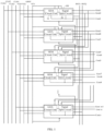
- a GOA drive circuit is provided. As shown in FIG. 1 , the GOA drive circuit includes multi-stage cascaded GOA circuits 100, and each stage of the GOA circuits 100 includes a GOA circuit unit 10 and a signal split circuit 20 that are in connection with each other.
- the signal split circuit 20 at each stage includes a first signal output end and a second signal output end for connecting two adjacent scanning lines.
- the signal split circuit 20 at each stage when triggered by several control signals including a first sub-line scan signal and a second sub-line scan signal output from the signal split circuit 20 at a fore-stage and/or an external control signal, is configured to split a line scan signal output from the GOA circuit unit 10 at a current stage into the first sub-line scan signal and the second sub-line scan signal and output the same to the first signal output end, the second signal output end and the signal split circuit 20 at a post-stage.
- a rising edge of the first sub-line scan signal output from the signal split circuit 20 at each stage is triggered simultaneously with a rising edge of the line scan signal output from the GOA circuit unit 10 at each stage, and.
- a falling edge of the second sub-line scan signal output from the signal split circuit 20 at each stage is triggered simultaneously with a falling edge of the line scan signal output from the GOA circuit unit 10 at each stage, and high-level duration of the first sub-line scan signal and the second sub-line scan signal output from the signal split circuit 20 at each stage are partially overlapped.
- the GOA circuit 100 is configured to receive an external control signal input by the drive circuit board through a bonding area on an array substrate, and convert the external control signal into a line scan signal.
- the external control signal includes a multi-channel clock signal, a frame start signal STV, a line scan high-level signal VGH, a line scan low-level signal VGL, a reset signal GRST, etc.
- the structure and operation mode of the GOA circuit unit 10 are same as the existing GOA circuit unit 10, such as the GOA circuit unit 10 of 4T1C or the GOA circuit unit 10 of 8T1C.
- the specific driving mode of the GOA drive circuit may be a unilateral driving or a bilateral driving, which will not be limited herein.
- the number of clock signals input to the GOA drive circuit may be four channels, or eight channels, etc., depending on the structure and working requirements of the GOA circuit 100 and the internal GOA circuit unit 10, which will not be limited herein.
- the GOA circuit unit 10 outputs line scan signals line by line according to the input control signals such as a one-channel clock signal, a frame start signal STV, etc. Meanwhile, the line scan signal output from the current stage serves as a reset signal of the GOA circuit unit 10 at the fore-stage, and an input signal of the GOA circuit unit 10 at the post-stage, the GOA circuit units 10 in different rows have influences to each other, thereby generating a shift pulse signal.
- the line scan signal output from the current stage is input to the signal split circuit 20 at the current stage for signal splitting, and is converted and output as two sub-line scan signals.
- the two sub-line scan signals are output as final line scan signals to drive two rows of pixel units line by line.
- the two sub-line scan signals respectively serve as the control signals of the signal split circuit 20 at the post-stage and the signal split circuit 20 at a stage after the post-stage, so that the signal split circuits 20 at all stages are correspondingly converted and split to generate the shift pulse signal, thereby driving the corresponding row of the pixel units on the array substrate. As shown in FIG.
- each GOA circuit unit 10 is configured to output first shift pulse signals Cout 1-Cout n according to the existing working mode, meanwhile, the signal split circuit 20 at each stage is configured to output second shift pulse signals Gout1-Gout n+1 according to several control signals including the received first and second sub-line scan signals output from the signal division circuit 20 at the fore-stage and/or the external control signal.
- one GOA circuit 100 is enabled to drive two rows of pixel units by arranging the signal split circuit 20, under the condition that the number of rows of the array substrate remains unchanged, the number of devices of the GOA circuit unit 10 can be reduced by half, with respect to the existing circuits, and the size of the frame of the display panel can be reduced, and thus the narrowing of the frame of the display panel can be realized.
- the signal split circuit 20 is configured to output the shifted first sub-line scan signal and the second sub-line scan signal according to each control signal, and the rising edge of the first sub-line scan signal output from the signal split circuit 20 at each stage is triggered simultaneously with the rising edge of the line scan signal output from the GOA circuit unit 10 at each stage, and the falling edge of the second sub-line scan signal output from the signal split circuit 20 at each stage is triggered simultaneously with the falling edge of the line scan signal output from the GOA circuit unit 10 at each stage.
- the first sub-line scan signal and the second sub-line scan signal follow the original line scan signal to be shifted and output synchronously, ensuring normal driving of pixel units in each row and improving driving reliability.
- the signal split circuit 20 at different stages may be triggered through different driving control signals to split and output the first sub-line scan signal and the second sub-line scan signal, and the specific driving control signals received by the signal split circuit 20 at different stages are not limited herein.
- the signal split circuit 20 may be split circuits having different switch structures, such as a shift circuit, a sequential circuit, and the like, and the specific structure of the signal split circuit 20 are not limited herein.
- the external control signal includes a multi-channel clock signal, a frame start signal STV, and a line scan high-level signal VGH, a line scan low-level signal VGL, a first pulse reset signal RST1 and a second pulse reset signal RST2.
- the falling edge of the first sub-line scan signal of the signal split circuit 20 at the j-th stage is triggered simultaneously with the rising edge of the first pulse reset signal RST1, and the falling edge of the first sub-line scan signal of the signal split circuit 20 at the j+1-th stage is triggered simultaneously with the rising edge of the second pulse reset signal RST2.
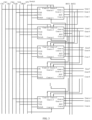
- the external clock signal, the line scan high-level signal VGH, the line scan low-level signal VGL, the frame start signal STV, the first pulse reset signal RST1 and the second pulse reset signal RST2 are input by the drive circuit board through the bonding area of the array substrate, as shown in FIG. 2 , the first pulse reset signal RST1 and the second pulse reset signal RST2 are in pulse waveforms, and are respectively configured to realize falling edge controls of the first sub-line scan signals of the signal split circuits 20 at odd-numbered stages and even-numbered stages.
- the driving mode of the signal split circuit 20 at each stage is similar to that of the GOA circuit unit 10 at each stage, that is, the signal split circuit 20 of the GOA circuit 100 at the first stage is triggered after receiving the frame start signal STV, the line scan high -level signal VGH, the line scan low-level signal VGL, the first pulse reset signal RST1 and the pull-down signal QB-n output from the GOA circuit unit 10 at the current stage to generate the first sub-line scan signal and the second sub-line scan signal of the signal split circuit at the first stage.
- the first sub-line scan signal and the second sub-line scan signal of the signal split circuit at the first stage are input to the first row of pixel units and the second row of pixel units of the array substrate, and meanwhile, the first sub-line scan signal of the signal split circuit at the first stage is input to the signal split circuit 20 at the second stage, and the second sub-line scan signal of the signal split circuit at first stage is input to the signal split circuit 20 at the third stage, serving as the drive control signals of the signal split circuit 20 at the second stage and the signal split circuit 20 at the third stage.
- the signal split circuit 20 at the second stage when triggered by the frame start signal STV, the line scan high-level signal VGH, the line scan low-level signal VGL, the second pulse reset signal RST2, and the pull-down signal QB-n output from the GOA circuit unit 10 at the current stage and the first sub-line scan signal output from the signal split circuit 20 at the first stage, is configured to split the line scan signal of the current-stage into the first sub-line scan signal and the second sub-line scan signal and output the same.
- the first sub-line scan signal of the signal split circuit at the second stage is input to the signal split circuit 20 at the third stage
- the second sub-line scan signal of the signal split circuit at the second stage is input to the signal split circuit 20 at the fourth stage, serving as the drive control signals of the signal split circuit 20 at the third stage and the signal split circuit 20 at the fourth stage.
- the GOA circuit unit 10 is integrated with the signal split circuit 20 to constitute a GOA chip.
- the GOA chip includes a clock signal pin CK for receiving a clock signal, a line scan high-level signal pin for receiving the line scan high-level signal VGH, a line scan low-level signal pin for receiving the line scan low-level signal VGL, a first signal input pin Cout n-2 for receiving an input signal, a second signal input pin Gout n-3 for receiving the second sub-line scan signal output from the corresponding fore-stage, and a third signal input pin Gout n-2 for receiving the first sub-line scan signal output from the corresponding fore-stage, a fourth signal input pin Cout n+1 for receiving the line scan signal output from the GOA chip at the post-stage, a reset pulse signal pin RST for receiving the corresponding reset pulse signal, a first signal output pin Cout n for outputting the line scan signal of the current stage, a second signal
- the frame start signal STV is input through the first signal input pin Cout n-2, the second signal input pin Gout n-3 and the third signal input pin Gout n-2 respectively.
- the frame start signal STV serving as the input signal of the GOA circuit unit 10 in the GOA chip at the first stage, is converted and output by the GOA circuit unit 10 as the line scan signal of the GOA circuit unit 10 at the first stage.
- the frame start signal STV, the line scan high-level signal VGH, the line scan low-level signal VGL, and the first pulse reset signal RST1, serving as the driving control signals of the signal split circuit 20 in the GOA chip at the first stage, are configured to control on-and-off of the signal split circuit 20, and the line scan signal of the GOA circuit unit 10 at the first stage is split and output as the first sub-line scan signal Gout1 and the second sub-line scan signal Gout2 of the current stage.
- the frame start signal STV is input through the first signal input pin Cout n-2 and the second signal input pin Gout n-3 respectively, and the first sub-line scan signal output from the GOA chip at the first stage is input through the third signal input pin Gout n-2, the frame start signal STV serving as the input signal of the GOA circuit unit 10 in the GOA chip at the second stage, is converted and output by the GOA circuit unit 10 as the line scan signal of the GOA circuit unit at the second stage.
- the frame start signal STV, the line scan high-level signal VGH, the line scan low-level signal VGL, the second pulse reset signal RST2, and the first sub-line scan signal output from the GOA chip at the first stage, serving as the driving control signals of the signal split circuit 20 in the GOA chip at the second stage, are configured to control the on-and-off of the signal split circuit 20, and the line scan signal of the GOA circuit unit at the second stage is split and output as the first sub-line scan signal Gout3 and the second sub-line scan signal Gout4 of the current stage.
- the line scan signal output from the GOA chip at the (i-2)-th stage is input through the first signal input pin Cout n-2
- the second sub-line scan signal output from the GOA chip at the (i-2)-th stage is input through the second signal input pin Gout n-3
- the first sub-line scan signal output from the GOA chip at the (i-1)-th stage is input through the third signal input pin Gout n-2.
- the line scan signal output from the GOA chip at the (i-2)-th stage, serving as the input signal of the GOA circuit unit 10 in the GOA chip at the current stage, is converted and output by the GOA circuit unit 10 as the line scan signal of the current stage.
- the frame start signal STV, the line scan high-level signal VGH, the line scan low-level signal VGL, the corresponding pulse reset signal, the second sub-line scan signal output from the GOA chip at the (i-2)-th stage, and the first sub-line scan signal output from the GOA chip at the (i-1)-stage, serving as the driving control signals of the signal split circuit 20 in the GOA chip at the current stage, are configured to control the on-and-off of the signal split circuit 20, and the line scan signal of the current stage is split and output as the first sub-line scan signal Gout n and the second sub-line scan signal Gout n+1 of the current stage.
- the signal split circuit 20 at each stage includes a first switch circuit 21, a second switch circuit 22 and a pull-down circuit 23.
- a signal output end of the first switch circuit 21 and a first signal end of the pull-down circuit 23 are connected in common to constitute the first signal output end of the signal split circuit 20, and a signal output end of the second switch circuit 22 and a second signal end of the pull-down circuit 23 are connected in common to constitute the second signal output end of the signal split circuit 20.
- the first switch circuit 21 and the second switch circuit 22 are also connected with a signal output end of the GOA circuit unit 10 at the current stage respectively.
- a controlled end of the pull-down circuit 23 is connected to a pull-down point of the GOA circuit unit 10 at the current stage, and configured for inputting the pull-down signal QB-n.
- the first switch circuit 21 is configured to be turned on and off correspondingly at corresponding timings according to a combination of levels of several signals including the corresponding pulse reset signal, the second sub-line scan signal output from the signal split circuit 20 at the fore-stage, the line scan high-level signal VGH, the line scan low-level signal VGL and the frame start signal STV, to output the first sub-line scan signal of the current stage.
- the second switch circuit 22 is configured to be turned on and off correspondingly at corresponding timings according to a combination of levels of several signals including the first sub-line scan signal output from the signal split circuit 20 at the fore-stage, the line scan low-level signal VGL and the frame start signal STV, to output the second sub-line scan signal of the current stage.
- the pull-down circuit 23 is configured to be turned on and off correspondingly at corresponding timings according to a combination of levels of the line scan low-level signal VGL and the pull-down signal QB-n, to enable the first sub-line scan signal and the second sub-line scan signal to be pulled down and reset.
- the first switch circuit 21 includes a first signal input end for inputting the second sub-line scan signal output from the signal split circuit 20 at the fore-stage, a second signal input end for inputting the pulse reset signal, a third signal input end for inputting the line scan high-level signal VGH, a fourth signal input end for inputting the line scan low-level signal VGL, and a fifth signal input end configured in connection with a signal output end of the GOA circuit unit 10 at the current stage.
- the second switch circuit 22 includes a first signal input end for inputting the first sub-line scan signal output from the signal split circuit 20 at the fore-stage, and a second signal input end for inputting the line scan low-level signal VGL, and a third signal input end configured in connection with a signal output end of the GOA circuit unit 10 at the current stage.
- the pull-down circuit 23 includes a first signal input end for inputting the line scan low-level signal VGL and a second signal input end configured in connection with a pull-down point of the GOA circuit unit 10 at the current stage.
- the pull-down point of the GOA circuit unit 10 at the current stage is a voltage at the pull-down point of the GOA circuit unit 10.
- the first switch circuit 21 when the first signal input end of the first switch circuit 21 is at a high level, the first switch circuit 21 is turned on, and the line scan signal output from the GOA circuit unit 10 at the current stage is output by the first switch circuit 21 at a low level.
- the first switch circuit 21 When the first signal input end of the first switch circuit 21 is turned off, the first switch circuit 21 continues to be turned on due to the coupling of internal capacitance, and the line scan signal output from the GOA circuit unit 10 at the current stage is output by the first switch circuit 21 at a high level.
- the first switch circuit 21 When the second signal input end, i.e., the pulse reset signal, is at a high level, the first switch circuit 21 is turned off, and a low level is output by the first switch circuit 21 as the internal capacitance is coupled to a low level, a first pulse signal representing the first sub-line scan signal is output from the first switch circuit 21, and meanwhile, when the pull-down signal QB-n is at a high level, the pull-down circuit 23 is turned on, a low level is output, and the first sub-line scan signal is pull-down and reset to a low level.
- the second switch circuit 22 When the first signal input end of the second switch circuit 22 is at a high level, the second switch circuit 22 is turned off, and a low level is output by the second switch circuit 22. When the first signal input end of the second switch circuit 22 is at a low level, the second switch circuit 22 is turned on, and the line scan signal output from the GOA circuit unit 10 at the current stage is output by the second switch circuit 22 at a high level.
- the second switch circuit 22 When the third signal input end of the second switch circuit 22 is at a low level, the second switch circuit 22 is at a low level due to the coupling of the internal capacitance, thereby outputting a second pulse signal representing the second sub-line scan signal, and meanwhile, when the pull-down signal QB-n is at a high level, the pull-down circuit 23 is turned on, a low level is output, the second sub-line scan signal is pulled down and reset to a low level.
- the split conversion of the line scan signal is realized, two channels of shifted sub-line scan signals are output, and thus the circuit structure is simple.
- the first switch circuit 21, the second switch circuit 22 and the pull-down circuit 23 may be controlled to be turned on and off correspondingly at corresponding timings by corresponding switch structures.
- the first switch circuit 21 includes a first electronic switch T1, a second electronic switch T2, a third electronic switch T3 and a first capacitor C1.
- a first end of the first electronic switch T1 is configured for inputting one of the frame start signal STV, the second sub-line scan signal output from the signal split circuit 20 at the fore-stage, and the line scan high-level signal VGH.
- a controlled end of the switch T1 is configured for inputting the frame start signal STV or the second sub-line scan signal output from the signal split circuit 20 at the fore-stage.
- a second end of the first electronic switch T1, a first end of the second electronic switch T2, a controlled end of the third electronic switch T3 and a first end of the first capacitor C1 are connected in common.
- a second end of the second electronic switch T2 is configured for inputting the line scan low-level signal VGL
- a controlled end of the second electronic switch T2 is configured for inputting the corresponding pulse reset signal
- a first end of the third electronic switch T3 is configured for inputting the line scan signal output from the GOA circuit unit 10 at the current stage.
- a second end of the third electronic switch T3 and a second end of the first capacitor C1 are connected in common to constitute the signal output end of the first switch circuit 21.
- the second switch circuit 22 includes a fourth electronic switch T4, a fifth electronic switch T5, a sixth electronic switch T6 and a second capacitor C2.
- a first end of the fourth electronic switch T4 is configured for inputting the line scan low-level signal VGL.
- a second end of the fourth electronic switch T4, a first end of the fifth electronic switch T5, a controlled end of the sixth electronic switch T6 and a first end of the second capacitor C2 are connected in common.
- a second end of the fifth electronic switch T5, a controlled end of the fifth electronic switch T5 and a first end of the sixth electronic switch T6 are connected in common and configured for inputting the line scan signal output from the GOA circuit unit 10 at the current stage.
- a controlled end of the fourth electronic switch T4 is configured for inputting the frame start signal STV or the first sub-line scan signal output from the signal split circuit 20 at the fore-stage.
- a second end of the sixth electronic switch T6 and a second end of the second capacitor C2 are connected in common to constitute the signal output end of the second switch circuit 22.
- the pull-down circuit 23 includes a seventh electronic switch T7 and an eighth electronic switch T8.
- a first end of the seventh electronic switch T7 serves as the first signal end of the pull-down circuit 23.
- a first end of the eighth electronic switch T8 serves as the second signal end of the pull-down circuit 23.
- a controlled end of the seventh electronic switch T7 and a controlled end of the eighth electronic switch T8 are connected in common and configured for inputting the pull-down signal QB-n.
- a second end of the seventh electronic switch T7 and a second end of the eighth electronic switch T8 are connected in common.
- the first electronic switch T1 when the controlled end and the first end of the first electronic switch T1 are at a high level, the first electronic switch T1 is turned on, and a high level is input to the third electronic switch T3, the third electronic switch T3 is turned on, the line scan signal output from the GOA circuit unit 10 at the current stage is output from the second end of the third electronic switch T3 at a low level.
- the third electronic switch T3 is turned off.
- the third electronic switch T3 When the first end of the third electronic switch T3 is at a high level, the third electronic switch T3 continues to turned on due to the coupling of the first capacitor C1 to output the line scan signal output from the GOA circuit unit 10 at the current stage at a high level.
- the pulse reset signal When the pulse reset signal is at a high level, the second electronic switch T2 is turned on, the line scan low-level signal VGL is input to the third electronic switch T3, the third electronic switch T3 is turned off, and the second end of the third electronic switch T3 is at a low level due to the coupling of the first capacitor C 1.
- the seventh electronic switch T7 When the pull-down signal QB-n is at a high level, the seventh electronic switch T7 is turned on, and a low level is output by the seventh electronic switch T7, so that the first sub-line scan signal output from the second end of the third electronic switch T3 is pulled down and reset.
- the fourth electronic switch T4 When the controlled end of the fourth electronic switch T4 is at a high level, the fourth electronic switch T4 is turned on, and a low level is input to the sixth electronic switch T6.
- the line scan signal When the line scan signal is at a low level, the fifth electronic switch T5 is turned off, the sixth electronic switch T6 is turned off, and a low level is output from the sixth electronic switch T6.
- the line scan signal is at a high level, the line scan signal and the voltage of the controlled end of the fourth electronic switch T4 are partially overlap, the fourth electronic switch T4 and the fifth electronic switch T5 are turned on simultaneously. By adjusting the size of the device, the sixth electronic switch T6 remains in an off state.
- the line scan signal continues to be at a high level, the sixth electronic switch T6 is turned on, and the line scan signal is output at a high level.
- the fifth electronic switch T5 is turned off, and the second end of the sixth electronic switch T6 is at a low level due to the coupling of the second capacitor C2.
- the eighth electronic switch T8 is turned on, and a low level is output by the eighth electronic switch T8, so that the second sub-line scan signal output from the second end of the six-electronic switch T6 is pulled down and reset.
- the splitting of the line scan signal is realized, the circuit structure is simple, the integrated arrangement of the GOA circuit 100 is convenient, and meanwhile, the size of the frame of the display panel is reduced, thereby achieving the narrow frame of the display panel.
- the signal split circuit 20 also includes a switch circuit 24.
- a first signal input end of the switch circuit 24, the signal output end of the first switch circuit 21 and the first signal end of the pull-down circuit 23 are connected in common.
- a second signal input end of the switch circuit 24, the second signal output end of the switch circuit 22 and the second signal end of the pull-down circuit 23 are connected in common.
- a third signal input end of the switch circuit 24 is configured for inputting the line scan signal output from the GOA circuit unit 10 at the current stage.
- a first signal output end and a second signal output end of the switch circuit 24 serve as the first signal output end and the second signal output end of the signal split circuit 20 respectively, and a controlled end of the switch circuit 24 is configured for inputting a switch selection signal Switch, the line scan high-level signal VGH, and the line scan low-level signal VGL.
- the switch circuit 24 is configured to be turned on and off according to the high or low level of the switch selection signal Switch, the line scan high-level signal VGH and the line scan low-level signal VGL, to enable the first sub-line scan signal and the second sub-line scan signal to be switched and output to the first signal output end and the second signal output end of the signal split circuit 20, or enable the line scan signal output from the GOA circuit unit 10 at the current stage to be output to the first signal output end and the second signal output end of the signal split circuit 20 respectively.
- the external control signal further includes the switch selection signal Switch, and the switch selection signal Switch is input to the switch circuit 24 to switch and output the two can signals.
- the switch selection signal Switch serves as a first level signal
- the third signal input end of the switch circuit 24 is in connection with the first signal output end and the second signal output end
- the line scan signal output from the GOA circuit unit 10 at the current stage is output to the first signal output end and the second signal output end of the split circuit 20 respectively
- two adjacent rows of pixel units connected to respectively the two signal output ends are turned on simultaneously, and the same data signal is input, and then the resolution of the array substrate is reduced.
- the switch selection signal Switch serves as a second level signal having opposite polarity to the first level signal
- the first signal input end of the switch circuit 24 is connected to the first signal output end of the switch circuit 24, and the second signal input end of the switch circuit 24 is connected the second signal output end of the switch circuit 24.
- the first sub-line scan signal and the second sub-line scan signal split and output by the first switch circuit 21, the second switch circuit 22 and the pull-down circuit 23 are respectively output to the first signal output end and the second signal output end of the signal split circuit 20, and two adjacent rows of pixel units are turned on row by row, as shown in FIG. 10 , in one embodiment, the first level signal is at a high level, and the second level signal is at a low level.
- the switch circuit 24 may be composed of different switching devices to realize the function of controlled switching of input and output, and the specific structure of the switch circuit 24 can be correspondingly arranged according to actual requirements.
- the switch circuit 24 includes a ninth electronic switch T9, a tenth electronic switch T10, and an eleventh electronic switch T11, a twelfth electronic switch T12, a thirteenth electronic switch T13, a fourteenth electronic switch T14, a fifteenth electronic switch T15 and a sixteenth electronic switch T16.
- a first end and a controlled end of the ninth electronic switch T9 are configured for inputting the line scan high-level signal VGH.
- a first end of the tenth electronic switch T10 is configured for inputting the line scan low-level signal VGL.
- a second end of the ninth electronic switch T9, a second end of the tenth electronic switch T 10 and a controlled end of the twelfth electronic switch T12 are connected in common.
- a first end of the twelfth electronic switch T12 serves as the first signal input end of the switch circuit 24.
- a second end of the twelfth electronic switch T12 and a second end of the eleventh electronic switch T11 are connected in common to constitute the first signal output end of the switch circuit 24.
- a first end of the eleventh electronic switch T11 and a first end of the fifteenth electronic switch T15 are connected in common to constitute the third signal input end of the switch circuit 24.
- a controlled end of the eleventh electronic switch T11, a controlled end of the tenth electronic switch T10, a controlled end of the fifteenth electronic switch T15 and a controlled end of the fourteenth electronic switch T14 are connected in common and configured for inputting the switch selection signal Switch.
- a first end and the controlled end of the thirteenth electronic switch T13 are configured for inputting the line scan high-level signal VGH.
- a first end of the fourteenth electronic switch T14 is configured for inputting the line scan low-level signal VGL.
- a second end of the thirteenth electronic switch T13, a second end of the fourteenth electronic switch T14 and a controlled end of the sixteenth electronic switch T16 are connected in common.
- a first end of the sixteenth electronic switch T 16 serves as the second signal input end of the switch circuit 24.
- a second end of the sixteenth electronic switch T 16 and a second end of the fifteenth electronic switch T15 are connected in common to constitute the second signal output end of the switch circuit 24.
- the switch selection signal Switch is at a high level
- the tenth electronic switch T10 and the fourteenth electronic switch T14 are turned on respectively, to output a low level to the twelfth electronic switch T12 and the sixteenth electronic switch T16 respectively, and the twelfth electronic switch T12 and the sixteenth electronic switch T16 are turned off.
- the eleventh electronic switch T10 and the fourteenth electronic switch T14 are turned on respectively, meanwhile, the eleventh electronic switch T11 and the fifteenth electronic switch T15 are also turned on respectively, the line scan signal output from the GOA circuit unit 10 at the current stage is output to the first signal output end and the second signal output end of the signal split circuit 20 respectively, the two adjacent rows of pixel units connected thereto are turned on simultaneously, and the same data signal is input, and then the resolution of the array substrate is reduced.
- the switch selection signal Switch When the switch selection signal Switch is at a low level, the tenth electronic switch T10, the eleventh electronic switch T11, the fourteenth electronic switch T14 and the fifteenth electronic switch T15 are turned off.
- the ninth electronic switch T9 and the thirteenth electronic switch T13 are turned on and a high level is input to the twelfth electronic switch T12 and the sixteenth electronic switch T16.
- the twelfth electronic switch T12 and the sixteenth electronic switch T16 are turned on.
- the first sub-line scan signal and the second sub-line scan signal split and output by the first switch circuit 21, the second switch circuit 22 and the pull-down circuit 23 are output to the first signal output end and the second signal output end of the signal split circuit 20, and then the two adjacent rows of pixel units are turned on row by row.
- the present application also provides a display panel, which includes an array substrate and a GOA drive circuit.
- the specific structure of the GOA drive circuit may refer to the above-mentioned embodiments.
- the display panel includes all solutions of the above-mentioned embodiments, and thus at least all the beneficial effects brought by the solutions of the above embodiments are included by the display panel of the present application, which will not be repeated here.
- the GOA drive circuit is arranged on one side or two sides of the array substrate.
- the array substrate includes a display area and a non-display area.
- the non-display area is provided with a bonding pin area and a GOA drive circuit.
- the GOA drive circuit is arranged on one side or two sides of the non-display area of the array substrate for the progressive scan of the display area, and the progressive scan driving of the display area is realized in conjunction with the data signal.
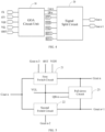
- the present application also provides a display device, which includes a backlight module, a drive circuit board and a display panel.
- the specific structure of the display panel may refer to the above-mentioned embodiments.
- the display device includes all solutions of all the above-mentioned embodiments, and thus at least all the beneficial effects brought by the solutions of the above embodiments are included by the display device of the present application, which will not be repeated here.
- the backlight module and the display panel are arranged opposite to each other, and the drive circuit board is electrical connection with the display panel.
- the backlight module is used to provide backlight.
- the drive circuit board is connected to the display panel through the chip on film.
- the external control signal is input to the driver chip in the chip on film, and the driver chip correspondingly converts the external control signal into a data signal and a control signal required for triggering the GOA drive circuit.
- the GOA drive circuit converts and outputs a shift pulse signal composed of multiple sub-line scan signals, and cooperates with the data signal to realize the progressive scan driving of the display area.
Landscapes
- Engineering & Computer Science (AREA)
- Physics & Mathematics (AREA)
- General Physics & Mathematics (AREA)
- Computer Hardware Design (AREA)
- Theoretical Computer Science (AREA)
- Chemical & Material Sciences (AREA)
- Crystallography & Structural Chemistry (AREA)
- Control Of Indicators Other Than Cathode Ray Tubes (AREA)
- Nonlinear Science (AREA)
- Mathematical Physics (AREA)
- Optics & Photonics (AREA)
- Shift Register Type Memory (AREA)
Applications Claiming Priority (2)
| Application Number | Priority Date | Filing Date | Title |
|---|---|---|---|
| CN202111096140.XA CN113554970B (zh) | 2021-09-18 | 2021-09-18 | Goa驱动电路、显示面板和显示装置 |
| PCT/CN2021/143379 WO2023040125A1 (zh) | 2021-09-18 | 2021-12-30 | 栅极集成驱动电路、显示面板和显示装置 |
Publications (2)
| Publication Number | Publication Date |
|---|---|
| EP4404178A1 true EP4404178A1 (de) | 2024-07-24 |
| EP4404178A4 EP4404178A4 (de) | 2025-05-07 |
Family
ID=78106587
Family Applications (1)
| Application Number | Title | Priority Date | Filing Date |
|---|---|---|---|
| EP21941017.2A Pending EP4404178A4 (de) | 2021-09-18 | 2021-12-30 | Gate-on-array-treiberschaltung, anzeigetafel und anzeigevorrichtung |
Country Status (6)
| Country | Link |
|---|---|
| US (1) | US12094389B2 (de) |
| EP (1) | EP4404178A4 (de) |
| JP (1) | JP7500780B2 (de) |
| KR (1) | KR102705644B1 (de) |
| CN (1) | CN113554970B (de) |
| WO (1) | WO2023040125A1 (de) |
Families Citing this family (6)
| Publication number | Priority date | Publication date | Assignee | Title |
|---|---|---|---|---|
| CN113554970B (zh) * | 2021-09-18 | 2022-01-14 | 惠科股份有限公司 | Goa驱动电路、显示面板和显示装置 |
| CN114242018B (zh) * | 2021-12-28 | 2023-05-23 | 深圳创维-Rgb电子有限公司 | Goa驱动电路、goa电路驱动方法及显示面板 |
| CN117392945B (zh) * | 2022-07-04 | 2024-10-25 | 荣耀终端有限公司 | 驱动信号输出电路、屏幕驱动电路、显示屏及电子设备 |
| JP2025056566A (ja) * | 2023-09-27 | 2025-04-08 | 株式会社ジャパンディスプレイ | 表示装置 |
| US20250140205A1 (en) * | 2023-10-30 | 2025-05-01 | Innolux Corporation | Electronic device |
| CN119942958B (zh) * | 2025-03-28 | 2025-10-17 | 京东方科技集团股份有限公司 | 显示控制电路、显示面板和显示装置 |
Family Cites Families (21)
| Publication number | Priority date | Publication date | Assignee | Title |
|---|---|---|---|---|
| JP5234728B2 (ja) | 2006-10-25 | 2013-07-10 | 株式会社日本触媒 | 耐熱アクリル樹脂の濾過方法、製造方法 |
| TWI402817B (zh) | 2009-09-07 | 2013-07-21 | Au Optronics Corp | 移位暫存器電路與其閘極訊號產生方法 |
| JP5755045B2 (ja) * | 2011-06-20 | 2015-07-29 | キヤノン株式会社 | 表示装置 |
| CN103474040B (zh) * | 2013-09-06 | 2015-06-24 | 合肥京东方光电科技有限公司 | 栅极驱动单元、栅极驱动电路和显示装置 |
| CN104517575B (zh) * | 2014-12-15 | 2017-04-12 | 深圳市华星光电技术有限公司 | 移位寄存器及级传栅极驱动电路 |
| CN104700799B (zh) * | 2015-03-17 | 2017-09-12 | 深圳市华星光电技术有限公司 | 栅极驱动电路及显示装置 |
| CN105261320B (zh) * | 2015-07-22 | 2018-11-30 | 京东方科技集团股份有限公司 | Goa单元驱动电路及其驱动方法、显示面板及显示装置 |
| CN106940987A (zh) * | 2016-01-04 | 2017-07-11 | 中华映管股份有限公司 | 驱动器及其驱动方法 |
| CN105741808B (zh) * | 2016-05-04 | 2018-02-16 | 京东方科技集团股份有限公司 | 栅极驱动电路、阵列基板、显示面板及其驱动方法 |
| CN106023937B (zh) * | 2016-07-28 | 2018-09-18 | 武汉华星光电技术有限公司 | 栅极驱动电路 |
| CN106601206B (zh) * | 2016-12-30 | 2019-01-11 | 深圳市华星光电技术有限公司 | Goa栅极驱动电路以及液晶显示装置 |
| CN106898319B (zh) * | 2017-02-20 | 2019-02-26 | 武汉华星光电技术有限公司 | 一种goa电路及液晶显示面板 |
| WO2018193912A1 (ja) * | 2017-04-17 | 2018-10-25 | シャープ株式会社 | 走査信号線駆動回路およびそれを備える表示装置 |
| CN107016971B (zh) * | 2017-04-18 | 2020-03-27 | 京东方科技集团股份有限公司 | 一种扫描电路单元、栅极驱动电路及扫描信号控制方法 |
| CN108648684B (zh) * | 2018-07-03 | 2021-08-10 | 京东方科技集团股份有限公司 | 移位寄存器单元、驱动方法、栅极驱动电路和显示装置 |
| JP7168368B2 (ja) * | 2018-07-26 | 2022-11-09 | Tianma Japan株式会社 | 表示装置 |
| US10769982B2 (en) * | 2018-08-31 | 2020-09-08 | Apple Inc. | Alternate-logic head-to-head gate driver on array |
| CN110390903B (zh) * | 2019-06-20 | 2022-12-30 | 昆山龙腾光电股份有限公司 | 栅极驱动电路及显示装置 |
| CN110322854B (zh) * | 2019-07-05 | 2021-07-06 | 信利半导体有限公司 | 一种goa驱动电路、阵列基板、和显示装置 |
| CN112863447A (zh) * | 2021-01-11 | 2021-05-28 | 深圳市华星光电半导体显示技术有限公司 | Goa电路及显示面板 |
| CN113554970B (zh) * | 2021-09-18 | 2022-01-14 | 惠科股份有限公司 | Goa驱动电路、显示面板和显示装置 |
-
2021
- 2021-09-18 CN CN202111096140.XA patent/CN113554970B/zh active Active
- 2021-12-30 JP JP2022573280A patent/JP7500780B2/ja active Active
- 2021-12-30 WO PCT/CN2021/143379 patent/WO2023040125A1/zh not_active Ceased
- 2021-12-30 EP EP21941017.2A patent/EP4404178A4/de active Pending
- 2021-12-30 KR KR1020227041717A patent/KR102705644B1/ko active Active
- 2021-12-30 US US17/924,494 patent/US12094389B2/en active Active
Also Published As
| Publication number | Publication date |
|---|---|
| JP2023544940A (ja) | 2023-10-26 |
| JP7500780B2 (ja) | 2024-06-17 |
| EP4404178A4 (de) | 2025-05-07 |
| US20240221587A1 (en) | 2024-07-04 |
| KR102705644B1 (ko) | 2024-09-11 |
| US12094389B2 (en) | 2024-09-17 |
| CN113554970B (zh) | 2022-01-14 |
| WO2023040125A1 (zh) | 2023-03-23 |
| KR20230042214A (ko) | 2023-03-28 |
| CN113554970A (zh) | 2021-10-26 |
Similar Documents
| Publication | Publication Date | Title |
|---|---|---|
| EP4404178A1 (de) | Gate-on-array-treiberschaltung, anzeigetafel und anzeigevorrichtung | |
| US7196685B2 (en) | Data driving apparatus and method for liquid crystal display | |
| US11538394B2 (en) | Gate driver circuit, display device and driving method | |
| CN115938324B (zh) | Goa电路及显示面板 | |
| CN114974163B (zh) | 扫描驱动电路、阵列基板和显示面板 | |
| US12315469B2 (en) | Gate drive circuit, drive device and display device | |
| US10522065B2 (en) | Transmitting electrode scan driving unit, driving circuit, driving method and array substrate | |
| TWI385633B (zh) | 用於一液晶顯示器之驅動裝置及其相關輸出致能訊號轉換裝置 | |
| GB2380848A (en) | Data driving apparatus and method for liquid crystal display | |
| CN108877720B (zh) | 栅极驱动电路、显示装置及驱动方法 | |
| US11823625B2 (en) | Display panel and display device | |
| US8077135B2 (en) | Source driver of LCD for black insertion technology | |
| CN111883041B (zh) | 驱动电路、显示面板及电子设备 | |
| CN114758635B (zh) | Goa电路及显示面板 | |
| CN113178174B (zh) | 一种栅极驱动模块、栅极控制信号的生成方法和显示装置 | |
| CN107871483B (zh) | 一种goa电路嵌入式触控显示面板 | |
| US11756499B2 (en) | Scan driving circuit with register part and pull-down part and display panel | |
| US11127330B1 (en) | Shift register allowing narrower bezel and display apparatus based thereon | |
| CN108091290B (zh) | 驱动电路和触控显示装置 | |
| US11488516B2 (en) | Circuit, method of driving panel, and display device | |
| US20250191540A1 (en) | Gate driving circuit and display device including the same | |
| CN120998153A (zh) | 一种阵列基板及显示装置 | |
| CN119252165A (zh) | 移位寄存器及其驱动方法、栅极驱动电路和显示装置 | |
| US20090066865A1 (en) | Signal generation apparatus for liquid crystal display device |
Legal Events
| Date | Code | Title | Description |
|---|---|---|---|
| STAA | Information on the status of an ep patent application or granted ep patent |
Free format text: STATUS: UNKNOWN |
|
| STAA | Information on the status of an ep patent application or granted ep patent |
Free format text: STATUS: THE INTERNATIONAL PUBLICATION HAS BEEN MADE |
|
| PUAI | Public reference made under article 153(3) epc to a published international application that has entered the european phase |
Free format text: ORIGINAL CODE: 0009012 |
|
| STAA | Information on the status of an ep patent application or granted ep patent |
Free format text: STATUS: REQUEST FOR EXAMINATION WAS MADE |
|
| 17P | Request for examination filed |
Effective date: 20221128 |
|
| AK | Designated contracting states |
Kind code of ref document: A1 Designated state(s): AL AT BE BG CH CY CZ DE DK EE ES FI FR GB GR HR HU IE IS IT LI LT LU LV MC MK MT NL NO PL PT RO RS SE SI SK SM TR |
|
| DAV | Request for validation of the european patent (deleted) | ||
| DAX | Request for extension of the european patent (deleted) | ||
| A4 | Supplementary search report drawn up and despatched |
Effective date: 20250409 |
|
| RIC1 | Information provided on ipc code assigned before grant |
Ipc: G09G 3/3266 20160101ALI20250403BHEP Ipc: G09G 3/36 20060101ALI20250403BHEP Ipc: G09G 3/20 20060101AFI20250403BHEP |