EP4403777A1 - Compresseur - Google Patents
Compresseur Download PDFInfo
- Publication number
- EP4403777A1 EP4403777A1 EP22869015.2A EP22869015A EP4403777A1 EP 4403777 A1 EP4403777 A1 EP 4403777A1 EP 22869015 A EP22869015 A EP 22869015A EP 4403777 A1 EP4403777 A1 EP 4403777A1
- Authority
- EP
- European Patent Office
- Prior art keywords
- accommodating cavity
- unloading
- compressor
- channel
- unloading device
- Prior art date
- Legal status (The legal status is an assumption and is not a legal conclusion. Google has not performed a legal analysis and makes no representation as to the accuracy of the status listed.)
- Pending
Links
Images


Classifications
-
- F—MECHANICAL ENGINEERING; LIGHTING; HEATING; WEAPONS; BLASTING
- F04—POSITIVE - DISPLACEMENT MACHINES FOR LIQUIDS; PUMPS FOR LIQUIDS OR ELASTIC FLUIDS
- F04C—ROTARY-PISTON, OR OSCILLATING-PISTON, POSITIVE-DISPLACEMENT MACHINES FOR LIQUIDS; ROTARY-PISTON, OR OSCILLATING-PISTON, POSITIVE-DISPLACEMENT PUMPS
- F04C18/00—Rotary-piston pumps specially adapted for elastic fluids
- F04C18/08—Rotary-piston pumps specially adapted for elastic fluids of intermeshing-engagement type, i.e. with engagement of co-operating members similar to that of toothed gearing
- F04C18/12—Rotary-piston pumps specially adapted for elastic fluids of intermeshing-engagement type, i.e. with engagement of co-operating members similar to that of toothed gearing of other than internal-axis type
- F04C18/14—Rotary-piston pumps specially adapted for elastic fluids of intermeshing-engagement type, i.e. with engagement of co-operating members similar to that of toothed gearing of other than internal-axis type with toothed rotary pistons
- F04C18/16—Rotary-piston pumps specially adapted for elastic fluids of intermeshing-engagement type, i.e. with engagement of co-operating members similar to that of toothed gearing of other than internal-axis type with toothed rotary pistons with helical teeth, e.g. chevron-shaped, screw type
-
- F—MECHANICAL ENGINEERING; LIGHTING; HEATING; WEAPONS; BLASTING
- F04—POSITIVE - DISPLACEMENT MACHINES FOR LIQUIDS; PUMPS FOR LIQUIDS OR ELASTIC FLUIDS
- F04C—ROTARY-PISTON, OR OSCILLATING-PISTON, POSITIVE-DISPLACEMENT MACHINES FOR LIQUIDS; ROTARY-PISTON, OR OSCILLATING-PISTON, POSITIVE-DISPLACEMENT PUMPS
- F04C28/00—Control of, monitoring of, or safety arrangements for, pumps or pumping installations specially adapted for elastic fluids
- F04C28/06—Control of, monitoring of, or safety arrangements for, pumps or pumping installations specially adapted for elastic fluids specially adapted for stopping, starting, idling or no-load operation
-
- F—MECHANICAL ENGINEERING; LIGHTING; HEATING; WEAPONS; BLASTING
- F04—POSITIVE - DISPLACEMENT MACHINES FOR LIQUIDS; PUMPS FOR LIQUIDS OR ELASTIC FLUIDS
- F04C—ROTARY-PISTON, OR OSCILLATING-PISTON, POSITIVE-DISPLACEMENT MACHINES FOR LIQUIDS; ROTARY-PISTON, OR OSCILLATING-PISTON, POSITIVE-DISPLACEMENT PUMPS
- F04C28/00—Control of, monitoring of, or safety arrangements for, pumps or pumping installations specially adapted for elastic fluids
- F04C28/10—Control of, monitoring of, or safety arrangements for, pumps or pumping installations specially adapted for elastic fluids characterised by changing the positions of the inlet or outlet openings with respect to the working chamber
- F04C28/12—Control of, monitoring of, or safety arrangements for, pumps or pumping installations specially adapted for elastic fluids characterised by changing the positions of the inlet or outlet openings with respect to the working chamber using sliding valves
-
- F—MECHANICAL ENGINEERING; LIGHTING; HEATING; WEAPONS; BLASTING
- F04—POSITIVE - DISPLACEMENT MACHINES FOR LIQUIDS; PUMPS FOR LIQUIDS OR ELASTIC FLUIDS
- F04C—ROTARY-PISTON, OR OSCILLATING-PISTON, POSITIVE-DISPLACEMENT MACHINES FOR LIQUIDS; ROTARY-PISTON, OR OSCILLATING-PISTON, POSITIVE-DISPLACEMENT PUMPS
- F04C28/00—Control of, monitoring of, or safety arrangements for, pumps or pumping installations specially adapted for elastic fluids
- F04C28/24—Control of, monitoring of, or safety arrangements for, pumps or pumping installations specially adapted for elastic fluids characterised by using valves controlling pressure or flow rate, e.g. discharge valves or unloading valves
- F04C28/26—Control of, monitoring of, or safety arrangements for, pumps or pumping installations specially adapted for elastic fluids characterised by using valves controlling pressure or flow rate, e.g. discharge valves or unloading valves using bypass channels
-
- F—MECHANICAL ENGINEERING; LIGHTING; HEATING; WEAPONS; BLASTING
- F04—POSITIVE - DISPLACEMENT MACHINES FOR LIQUIDS; PUMPS FOR LIQUIDS OR ELASTIC FLUIDS
- F04C—ROTARY-PISTON, OR OSCILLATING-PISTON, POSITIVE-DISPLACEMENT MACHINES FOR LIQUIDS; ROTARY-PISTON, OR OSCILLATING-PISTON, POSITIVE-DISPLACEMENT PUMPS
- F04C29/00—Component parts, details or accessories of pumps or pumping installations, not provided for in groups F04C18/00 - F04C28/00
- F04C29/12—Arrangements for admission or discharge of the working fluid, e.g. constructional features of the inlet or outlet
Definitions
- the present application relates to a compressor, and in particular, to a screw compressor having an unloading device.
- a screw compressor is a common component in a refrigeration unit.
- tooth space volumes of a pair of screw rotors mesh with each other, leading to changes in elementary volume composed of tooth-shaped space, thereby completing a process of gas suction, compression, and exhaust.
- the pair of screw rotors that are meshed with each other are arranged in parallel in a body of the screw compressor, wherein one end of the screw rotor is a suction end, which is communicated with a suction port of the body; and the other end is an exhaust end, which is communicated with an exhaust port of the body.
- the present application provides a compressor comprising: a housing provided with a rotor accommodating cavity and an exhaust cavity; a pair of screw rotors at least partially located in the rotor accommodating cavity, a compression accommodating cavity being formed between teeth of the pair of screw rotors and the housing, and the pair of screw rotors having a suction end and an exhaust end, wherein the housing further comprises an unloading channel and a connecting channel, the unloading channel is provided with an unloading channel inlet and an unloading channel outlet, the unloading channel inlet can be communicated with the compression accommodating cavity through the connecting channel, and the unloading channel outlet is communicated with a suction side of the compressor; and an unloading device configured to controllably open or close the connecting channel, such that the compression accommodating cavity can be controllably communicated with or disconnected from the connecting channel.
- the unloading device is configured that: when the compressor is started, the unloading device opens the connecting channel, thereby opening the inlet of the unloading channel, such that the compression accommodating cavity is communicated with a suction side of the compressor.
- the housing further comprises an unloading device accommodating cavity and a cover, a proximal end of the unloading device accommodating cavity forms the connecting channel, and a distal end of the unloading device accommodating cavity is closed by the cover.
- the unloading device accommodating cavity has an unloading device accommodating cavity opening, and an area of the unloading device accommodating cavity opening is larger than an area of the inlet of the unloading channel.
- the exhaust end of the pair of screw rotors has an exhaust end surface, the unloading device accommodating cavity opening, the inlet of the unloading channel, and the exhaust end surface are on the same plane, and the unloading device accommodating cavity opening can simultaneously overlap at least a part of the inlet of the unloading channel and at least a part of the exhaust end surface.
- the unloading device comprises a piston movable in the unloading device accommodating cavity and an elastic device capable of providing an elastic force, wherein the unloading device is configured that: when the pressure on the piston is less than the elastic force of the elastic device, the piston can move away from the inlet of the unloading channel, thereby opening the connecting channel; and when the pressure on the piston is greater than the elastic force of the elastic device, the piston can close the inlet of the unloading channel, thereby closing the connecting channel, wherein the pressure is provided by gas exhaust pressure of the compressor.
- the piston has a head and a body, wherein a diameter of the head is greater than a diameter of the body;
- the unloading device accommodating cavity has a first section and a second section, wherein a diameter of the second section is smaller than a diameter of the first section, the first section is close to the cover, and the head is accommodated in the first section and forms a seal with an inner wall of the first section; and one end of the elastic device abuts against a step surface formed by the first section and the second section, and the other end abuts against the head of the piston, wherein the elastic device provides an elastic force, such that the piston can be away from the inlet of the unloading channel, thereby opening or closing the connecting channel, and the head of the piston can be subjected to a pressure, such that the piston moves towards the inlet of the unloading channel to close the connecting channel.
- the unloading device accommodating cavity is communicated with the exhaust cavity of the compressor through a connecting passage, and a throttling element is disposed on the connecting passage.
- a buffer device is disposed on the connecting passage, and the buffer device is arranged between the unloading device accommodating cavity and the throttling element.
- the cover is provided with a cover channel, and the cover channel forms the throttling element.
- the throttling element and the buffer device are disposed in the housing.
- the housing has a housing fitting surface disposed facing the exhaust end surface of the exhaust end of the pair of screw rotors, an exhaust port is disposed on the housing fitting surface, and in a radial direction, there is a distance between the unloading device accommodating cavity opening and the exhaust port.
- the compressor in the present application has an unloading device, which can reduce the load of the compression upon startup of the compressor, and restore the load when the compressor runs smoothly.
- the unloading device in the present application can be adjusted according to a working state of the compressor.
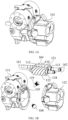
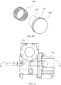
- FIG. 1A is a partial perspective view of a screw compressor according to an embodiment of the present application
- FIG. 1B is an exploded view of the screw compressor shown in FIG. 1A
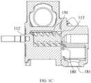
- FIG. 1C is an axial cross-sectional view of the screw compressor shown in FIG. 1A
- FIGs. 1A-1C show some components of the screw compressor.
- the screw compressor comprises a housing 101, a pair of screw rotors 110, and unloading devices 109 and 119.
- the housing 101 comprises a rotor seat 131 and an exhaust seat 132.
- the rotor seat 131 has a rotor accommodating cavity 105 for accommodating the pair of screw rotors 110.
- the rotor seat 131 has an exhaust cavity 180, and the exhaust cavity 180 is communicated with an exhaust port 181 of the compressor.
- the pair of screw rotors 110 comprise a male rotor 121 and a female rotor 122 that are meshed with each other, and the male rotor 121 and the female rotor 122 can be driven to rotate.
- the pair of screw rotors 110 comprise a tooth portion 160 and shaft portions 161 and 162 that are connected to two ends of the tooth portion 160, respectively.
- the male rotor 121 has a plurality of spiral teeth, and grooves are formed between adjacent teeth; and the female rotor 122 also has a plurality of spiral teeth, and grooves are also formed between adjacent teeth.
- the teeth and the corresponding grooves of the male rotor 121 and the female rotor 122 form an intermeshing structure, and form a compression accommodating cavity together with the housing 101 (refer to FIG. 5A ).
- the tooth portion 160 of the pair of screw rotors 110 has a suction end 112 and an exhaust end 113. Gas is sucked into the compression accommodating cavity 150 at the suction end 112, and gradually moves towards the exhaust end 113 as the pair of screw rotors 110 rotate. At the same time, the volume of the compression accommodating cavity 150 gradually decreases as the pair of screw rotors 110 rotate, and the gas in the compression accommodating cavity 150 is gradually compressed. The compressed gas enters the exhaust cavity 180 of the compressor from the exhaust end 113, and then is exhausted from the exhaust port 181 of the compressor.
- the exhaust end 113 has an exhaust end surface 118.
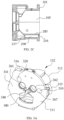
- FIG. 2A is a perspective view of the rotor seat shown in FIG. 1B
- FIG. 2B is a side view of the rotor seat shown in FIG. 2A
- FIG. 2C is a cross-sectional view of the rotor seat shown in FIG. 2B sectioned along a line A-A.
- the rotor seat 131 comprises a front end 211 of the rotor seat and a rear end 212 of the rotor seat.
- the front end 211 of the rotor seat is close to the suction end 112 of the pair of screw rotors 110, and the rear end 212 of the rotor seat is close to the exhaust end 113 of the pair of screw rotors 110.
- the rear end 212 of the rotor seat is connected to the exhaust seat 132, and the rear end 212 of the rotor seat has a rear end surface 207.
- the rotor accommodating cavity 105 extends through the rear end surface 207 to form a rotor accommodating cavity opening 215.
- the rotor seat 131 has an unloading channel 208 and an unloading channel 209 that fit with the unloading device 109 and the unloading device 119, respectively.
- the unloading channel 208 and the unloading channel 209 are located on two sides of the rotor accommodating cavity 105 in the axial direction, respectively, so as to be close to the female rotor 122 and the male rotor 121, respectively.
- the unloading channel 208 and the unloading channel 209 have similar structures but different positions, and the unloading channel 208 is used as an example to introduce the structure of the unloading channel below. In other embodiments, one or more unloading channels may be disposed according to an actual requirement.
- the unloading channel 208 extends in a direction from the front end 211 to the rear end of the rotor seat and is arranged side by side with the compression accommodating cavity 150.
- the unloading channel 208 is separated from the rotor accommodating cavity 105 by a partition wall 285.
- the unloading channel 208 has an unloading channel inlet 216 and an unloading channel outlet 217.
- the unloading channel inlet 216 is located on the rear end surface 207 and is disposed spaced from the rotor accommodating cavity opening 215.
- the unloading channel outlet 217 is close to the suction end 112 of the pair of screw rotors and is communicated with the rotor accommodating cavity 105.
- the unloading channel outlet 217 is disposed to be communicated with the suction side of the compressor.
- the unloading channel 208 is used to communicate the unloading channel inlet 216 located on the rear end surface 207 with the suction side of the compressor.
- the unloading channel 208 may extend in another direction within the rotor seat 131, and an inner cavity of the unloading channel 208 may have two or more sections with different shapes.
- FIG. 3A is a perspective view of the exhaust seat shown in FIG. 1B
- FIG. 3B is a side view of the exhaust seat shown in FIG. 3A
- FIG. 3C is a cross-sectional view of the exhaust seat shown in FIG. 3B sectioned along a line B-B
- FIG. 3D is a front view of the exhaust seat shown in FIG. 3A .
- the exhaust seat 132 has a first end 311 and a second end 312, and the first end 311 is connected to the rotor seat 131.
- An end surface of the first end 311 forms a housing fitting surface 341, and the housing fitting surface 341 fits with the rear end surface 207 of the rotor seat 131.
- the exhaust seat 132 has rotor shaft accommodating cavities 361 and 362, an exhaust cavity 180, and unloading device accommodating cavities 310 and 320.
- the rotor shaft accommodating cavities 361 and 362 are used to accommodate a shaft of the screw rotor 110, and the rotor shaft accommodating cavities 361 and 362 form rotor shaft openings 371 and 372 on the housing fitting surface 341.
- the exhaust cavity 180 forms an exhaust cavity opening 366 on the housing fitting surface 341.
- the unloading device accommodating cavities 310 and 320 form unloading device accommodating cavity openings 367 and 368 on the housing fitting surface 341. There is a distance between the exhaust cavity opening 366 and the unloading device accommodating cavity openings 367 and 368.
- rotor projection area 382 on the housing fitting surface 341, wherein the rotor projection area 382 is a projection area formed on the housing fitting surface 341 in the axial direction during rotation of the pair of screw rotors 110.
- the rotor projection area 382 is approximately of an "8" shape and is disposed around the rotor shaft openings 371 and 372.
- the rotor projection area 382 has a sealing area 326, a first opening area 328, and second opening areas 338 and 339.
- An overlapping portion of the exhaust cavity opening 366 with the rotor projection area 382 forms the first opening area 328, overlapping portions of the unloading device accommodating cavity openings 367 and 368 with the rotor projection area 382 form the second opening areas 338 and 339, and the remaining portion forms the sealing area 326.
- the second opening areas 338 and 339 are located, relative to the first opening area 328, downstream of the rotation direction of the corresponding screw rotor, respectively. In other words, during rotation, the screw rotor first passes through the second opening areas 338 and 339, and then reaches the first opening area 328.
- the compression accommodating cavity 150 forms an end of the compression accommodating cavity 150 on a plane on which the exhaust end surface 118 of the pair of screw rotors is located.
- the sealing area 326 can seal the end of the compression accommodating cavity 150, such that the compression accommodating cavity 150 can form a sealed space.
- the compression accommodating cavity 150 is disconnected from the exhaust cavity 180, and refrigerant gas in the compression accommodating cavity 150 can be compressed; when the end of the compression accommodating cavity 150 is aligned or partially aligned with the first opening area 328, the compression accommodating cavity 150 is communicated with the exhaust cavity 180, and the gas in the compression accommodating cavity 150 can be exhausted; and when the end of the compression accommodating cavity 150 is aligned or partially aligned with the second opening areas 338 and 339, the compression accommodating cavity 150 is selectively communicated with or disconnected from the unloading channel.
- a selective communicating relationship between the compression accommodating cavity 150 and the unloading channel will be described in detail below.
- the exhaust seat 132 further comprises covers 315 and 316 for covering distal ends of the unloading device accommodating cavities 310 and 320, respectively.
- the unloading device accommodating cavities 310 and 320 have similar structures but different positions, and the unloading device accommodating cavity 310 is used as an example to introduce the structure thereof below.
- the unloading device accommodating cavity 310 is formed by extending the unloading device accommodating cavity opening 367 towards the inside of the exhaust seat.
- the distal end (namely, an end away from the unloading device accommodating cavity opening 367) of the unloading device accommodating cavity 310 is closed by the cover 315.
- the unloading device accommodating cavity 310 has a first section 321 and a second section 322, the first section 321 is close to the unloading device accommodating cavity opening 367, and the second section 322 is close to the cover 315.
- a diameter of the second section 322 is less than a diameter of the first section 321, such that a step surface 333 is formed at a joint of the first section 321 and the second section 322.
- a shape of the unloading device accommodating cavity 310 is configured to fit with the unloading device 109, such that the unloading device 109 can move within the unloading device accommodating cavity 310.
- the unloading device accommodating cavity 310 has a connecting channel 308, wherein the connecting channel 308 is formed by a part of the first section 321 of the unloading device accommodating cavity 310 close to the unloading device accommodating cavity opening 367. That is, the connecting channel 308 is a portion of the first section 321.
- the cover 315 is provided with a cover channel 380, wherein an extension direction of the cover channel 380 is substantially the same as an extension direction of the unloading device accommodating cavity 310.
- the cover channel 380 extends through the cover 315 to form a through hole on the cover 315.
- the cover channel 380 communicates the unloading device accommodating cavity 310 with a high-pressure side of the compressor.
- a diameter of the cover channel 380 is thin, such that the cover channel 380 can be used as a throttling element to control a flow of fluid into the unloading device accommodating cavity 310 through the cover channel 380.
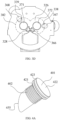
- FIG. 4A is a perspective view of the unloading device
- FIG. 4B is an exploded view of the unloading device shown in FIG. 4A
- the unloading device 109 comprises a piston 401 and an elastic device 402.
- the piston 401 has a head 411 and a body 412.
- a diameter of the head 411 is greater than a diameter of the body 412, wherein an outer diameter of the head 411 matches an inner diameter of the first section 321 of the unloading device accommodating cavity 310, an outer diameter of the body 412 matches an inner diameter of the second section 322 of the unloading device accommodating cavity 310, the head 411 is accommodated in the first section 321, and the body 412 is accommodated in the second section 322.
- a length of the first section 321 of the unloading device accommodating cavity 310 is greater than a length of the head 411 of the piston 401, and a length of the second section 322 of the unloading device accommodating cavity 310 is greater than a length of the body 412 of the piston 401, such that the piston 401 can move within a range in the axial direction in the unloading device accommodating cavity 310.
- the head 411 has an inner surface 421 and an outer surface 422 that are disposed opposite to each other, and a side surface 423 connecting the inner surface 421 and the outer surface 422.
- the inner surface 421 faces the body 412 and the outer surface 422 is away from the body 412.
- the elastic device 402 is a spring, and the elastic device 402 is sleeved on the body 412 of the piston. One end of the elastic device 402 abuts against the inner surface 421 of the head 411 or is connected to the inner surface 421 of the head 411.
- a seal ring can be provided on the side surface 423 of the head to enhance a seal between the head 411 and the inner wall of the first section 321.
- a distal end of the body 412 has a piston sealing end surface 455.
- a shape of the piston sealing end surface 455 matches a shape of the unloading device accommodating cavity opening 367, such that the piston sealing end surface 455 can seal the unloading device accommodating cavity opening 367.
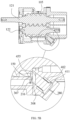
- FIG. 5A is a side view of the screw compressor shown in FIG. 1A
- FIG. 5B is a cross-sectional view of the screw compressor shown in FIG. 5A sectioned along a line C-C, showing the piston in an opened position
- FIG. 5C is another cross-sectional view of the screw compressor shown in FIG. 5A sectioned along the line C-C, showing the piston in a closed position.
- the unloading device accommodating cavity opening 367 is simultaneously aligned with at least a part of the unloading channel inlet 216 and a part of the screw rotor accommodating cavity opening 215.
- the unloading device accommodating cavity 310 can communicate the end of the compression accommodating cavity 150 with the unloading channel 208.
- the piston 401 In the position shown in FIG. 5A , the piston 401 is in the opened position. One end of the elastic device 402 abuts against the inner surface 421 of the head 411 of the piston 401, and the other end abuts against the step surface 333 formed at the joint between the first section 321 and the second section 322.
- the elastic device 402 is in a compressed state, thereby providing the piston 401 with an elastic force in a direction away from the unloading device accommodating cavity opening 367.
- the piston 401 is not subjected to an external force opposite to the direction of the elastic force, or is subjected to an external force less than the elastic force of the elastic device, such that the piston 401 is in the farthest position relative to the unloading device accommodating cavity opening 367.
- the head of the piston 401 abuts against the cover 315 and cannot move further in a direction towards the unloading device accommodating cavity opening 367.
- the connecting channel 308 has a cavity, such that the connecting channel 308 communicates the compression accommodating cavity 150 and the unloading channel 208.
- the compression accommodating cavity 150 is not yet communicated with the exhaust cavity opening 366, and a part of the compressed refrigerant gas in the compression accommodating cavity 150 is communicated with the suction side of the compressor through the unloading channel 208, thereby reducing the load of the compressor.
- the piston 401 In the position shown in FIG. 5B , the piston 401 is in the closed position.
- the piston 401 is subjected to a force opposite to the direction of the elastic force of the elastic device, which can overcome the elastic force of the elastic device, such that the piston 401 enters the connecting channel 308 and abuts against the rear end surface 207 of the rotor seat 131.
- the connecting channel 308 is filled by the body of the piston 401, such that the connecting channel 308 is closed.
- the piston sealing end surface 455 is flush with the unloading device accommodating cavity opening 367 and seals the unloading device accommodating cavity opening 367.
- the compression accommodating cavity 150 and the unloading channel 208 are blocked by the piston sealing end surface 455 and cannot communicate with each other.
- the refrigerant in the compression accommodating cavity 150 continues to be compressed before entering the exhaust cavity 180.
- the cover channel 380 on the cover 315 is communicated with the exhaust side of the compressor, such that the pressure on the outer surface 422 of the head 411 of the piston 401 changes as the pressure on the exhaust side of the compressor changes.
- the piston in the present application can be automatically adjusted according to a working state of the compressor, wherein when the compressor is just started, the piston 401 is in the opened position, and when the compressor runs smoothly, the piston 401 is in the closed position.
- a small load is conducive to reducing a starting torque, thereby facilitating quick startup of the compressor.
- the pressure on the exhaust side of the compressor is small and cannot overcome the elastic force of the elastic device to cause the piston to seal the unloading device accommodating cavity opening 367.
- the connecting channel 308 is opened, and a part of gas entering the compression accommodating cavity 150 reaches the suction side of the compressor through the connecting channel 308 and the unloading channel 208, and is not subjected to compression, such that a suction volume of the compressor decreases, and in this case, the load of the compression is small.
- the compressor operation reaches a stable state, the pressure on the exhaust side of the compressor increases, and the pressure on the exhaust side is exerted on the piston 401 through the cover channel 380, causing the piston 401 to move towards where the piston seals the unloading device accommodating cavity opening 367 and into the farthermost position.
- the connecting channel 308 is filled by the piston 401 and thus is closed, and the compression accommodating cavity 150 is disconnected from the unloading channel 208.
- the compressor reaches a full load state. Opening and closing of the piston 401 is automatically associated with the working state of the compressor and does not require manual intervention.
- positions of the unloading device accommodating cavity openings 367 and 368 can be set as required.
- the distance between the unloading device accommodating cavity openings 367 and 368 and the exhaust cavity opening 366 can affect an unloading capability of the unloading device.
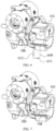
- FIG. 6 is a schematic view of a first embodiment of a connection relationship between the unloading device accommodating cavity 310 of the compressor and the exhaust cavity of the compressor according to the present application.
- the cover channel 380 is communicated with the exhaust cavity of the compressor through a connecting passage 608.
- a throttling element 611 and a buffer device 612 are disposed on the connecting passage, wherein the buffer device 612 is disposed between the throttling element 611 and the cover 315.
- the throttling element 611 and the buffer device 612 are used to reduce the pressure of the refrigerant gas on the exhaust side of the compressor exerted on the unloading device 109, thereby preventing the unloading device 109 from being subjected to excessive impact.
- the buffer device 612 disposed on the throttling element 611 can be configured according to an actual requirement for the compressor, and in one embodiment, the throttling element 611 can meet the requirement, so the buffer device 612 does not need to be disposed. In another embodiment, a plurality of stages of throttling elements and buffer devices may be disposed. In yet another embodiment, the cover channel 380 is thin, such that the throttling element is formed from the cover channel 380 to further throttle the refrigerant gas.
- the cover channel 380 may be communicated with any place on a high-pressure side of the air conditioning system.
- FIG. 7 is a schematic view of a second embodiment of the connection relationship between the unloading device accommodating cavity 310 of the compressor and the exhaust cavity of the compressor according to the present application.
- This embodiment is similar to the embodiment shown in FIG. 6 , and a difference lies in that in the embodiment of FIG. 7 , the connecting passage 708 is disposed in the housing 101 of the compressor.
- the embodiment shown in FIG. 7 is more compact and can achieve the same technical effects.
- FIG. 8 is a schematic view of a third embodiment of the connection relationship between the unloading device accommodating cavity 310 of the compressor and the exhaust cavity of the compressor according to the present application.
- the buffer device is formed by a cover.
- a cover 815 has a thickness in the axial direction, and there is a cover accommodating cavity 830 inside the cover, wherein the cover accommodating cavity 830 is communicated with the unloading device accommodating cavity 310.
- the cover accommodating cavity 830 has a volume and can provide a buffering effect, thereby forming the buffer device.
- the compressor in the present application can automatically adjust a load state during startup and smooth running, such that the compressor is in a good working state.
Landscapes
- Engineering & Computer Science (AREA)
- Mechanical Engineering (AREA)
- General Engineering & Computer Science (AREA)
- Physics & Mathematics (AREA)
- Fluid Mechanics (AREA)
- Applications Or Details Of Rotary Compressors (AREA)
Applications Claiming Priority (2)
| Application Number | Priority Date | Filing Date | Title |
|---|---|---|---|
| CN202111098490.XA CN113982916A (zh) | 2021-09-18 | 2021-09-18 | 压缩机 |
| PCT/CN2022/115501 WO2023040643A1 (fr) | 2021-09-18 | 2022-08-29 | Compresseur |
Publications (2)
| Publication Number | Publication Date |
|---|---|
| EP4403777A1 true EP4403777A1 (fr) | 2024-07-24 |
| EP4403777A4 EP4403777A4 (fr) | 2025-06-25 |
Family
ID=79736069
Family Applications (1)
| Application Number | Title | Priority Date | Filing Date |
|---|---|---|---|
| EP22869015.2A Pending EP4403777A4 (fr) | 2021-09-18 | 2022-08-29 | Compresseur |
Country Status (6)
| Country | Link |
|---|---|
| US (1) | US20250122875A1 (fr) |
| EP (1) | EP4403777A4 (fr) |
| KR (1) | KR20240090204A (fr) |
| CN (1) | CN113982916A (fr) |
| TW (1) | TW202314121A (fr) |
| WO (1) | WO2023040643A1 (fr) |
Families Citing this family (2)
| Publication number | Priority date | Publication date | Assignee | Title |
|---|---|---|---|---|
| CN113982916A (zh) * | 2021-09-18 | 2022-01-28 | 江森自控空调冷冻设备(无锡)有限公司 | 压缩机 |
| CN114688024B (zh) * | 2022-03-09 | 2024-04-05 | 江森自控空调冷冻设备(无锡)有限公司 | 螺杆压缩机 |
Family Cites Families (19)
| Publication number | Priority date | Publication date | Assignee | Title |
|---|---|---|---|---|
| GB1335024A (en) * | 1969-12-31 | 1973-10-24 | Howden Godfrey Ltd | Compressor control |
| SE456264B (sv) * | 1980-09-19 | 1988-09-19 | Mitsubishi Heavy Ind Ltd | Anordning for kapacitetsreglering vid skruvkompressorer |
| JPS61265381A (ja) * | 1985-05-20 | 1986-11-25 | Hitachi Ltd | スクリユ−圧縮機のガス噴射装置 |
| SE464885B (sv) * | 1988-04-25 | 1991-06-24 | Svenska Rotor Maskiner Ab | Skruvkompressor med lyftventil |
| JP2814272B2 (ja) * | 1989-10-05 | 1998-10-22 | 北越工業株式会社 | 回転圧縮機の容量制御方法 |
| SE503852C2 (sv) * | 1994-11-30 | 1996-09-16 | Svenska Rotor Maskiner Ab | Roterande skruvkompressor med avlastningsanordning |
| SE9803292L (sv) * | 1998-09-29 | 1999-05-17 | Svenska Rotor Maskiner Ab | Skruvrotorkompressor med variabel kapacitet, vilken kompressor innefattar minst en lyftventil i anslutning till en första kompressionskammare |
| US6494699B2 (en) * | 2000-08-15 | 2002-12-17 | Thermo King Corporation | Axial unloading lift valve for a compressor and method of making the same |
| ES2588578T3 (es) * | 2005-02-24 | 2016-11-03 | Carrier Corporation | Válvula de descarga de compresor |
| JP2008240579A (ja) * | 2007-03-26 | 2008-10-09 | Hitachi Industrial Equipment Systems Co Ltd | 二軸スクリュー式空気圧縮機 |
| CN201269315Y (zh) * | 2008-09-12 | 2009-07-08 | 徐道敏 | 具有不等径活塞的两位两通控制阀 |
| JP5383632B2 (ja) * | 2010-11-26 | 2014-01-08 | 株式会社神戸製鋼所 | スクリュ圧縮機 |
| WO2015094466A1 (fr) * | 2013-12-19 | 2015-06-25 | Carrier Corporation | Compresseur à soupape à indice de volume variable |
| CN204099200U (zh) * | 2014-09-23 | 2015-01-14 | 江森自控空调冷冻设备(无锡)有限公司 | 可调内容积比的螺杆压缩机 |
| CN210033838U (zh) * | 2019-03-19 | 2020-02-07 | 福建雪人股份有限公司 | 一种用于螺杆压缩机的柱塞式容量调节装置 |
| CN110578690B (zh) * | 2019-10-21 | 2024-10-29 | 无锡锡压压缩机有限公司 | 一种两级螺杆空气压缩机的级间压力调节结构 |
| CN210769318U (zh) * | 2019-10-21 | 2020-06-16 | 无锡锡压压缩机有限公司 | 一种两级螺杆空气压缩机的级间压力调节结构 |
| CN211900969U (zh) * | 2019-12-24 | 2020-11-10 | 湖南唯特气体压缩机械制造有限公司 | 一种空载启动式制冷螺杆压缩机 |
| CN113982916A (zh) * | 2021-09-18 | 2022-01-28 | 江森自控空调冷冻设备(无锡)有限公司 | 压缩机 |
-
2021
- 2021-09-18 CN CN202111098490.XA patent/CN113982916A/zh active Pending
-
2022
- 2022-08-29 WO PCT/CN2022/115501 patent/WO2023040643A1/fr not_active Ceased
- 2022-08-29 KR KR1020247012964A patent/KR20240090204A/ko active Pending
- 2022-08-29 US US18/693,124 patent/US20250122875A1/en not_active Abandoned
- 2022-08-29 EP EP22869015.2A patent/EP4403777A4/fr active Pending
- 2022-09-05 TW TW111133597A patent/TW202314121A/zh unknown
Also Published As
| Publication number | Publication date |
|---|---|
| KR20240090204A (ko) | 2024-06-21 |
| US20250122875A1 (en) | 2025-04-17 |
| EP4403777A4 (fr) | 2025-06-25 |
| CN113982916A (zh) | 2022-01-28 |
| TW202314121A (zh) | 2023-04-01 |
| WO2023040643A1 (fr) | 2023-03-23 |
Similar Documents
| Publication | Publication Date | Title |
|---|---|---|
| EP4403777A1 (fr) | Compresseur | |
| EP3812591B1 (fr) | Robinet à tiroir, mécanisme de réglage de robinet à tiroir et compresseur à vis | |
| WO1997045642A1 (fr) | Compresseur a rotor | |
| US20110070114A1 (en) | Oil return valve for a scroll compressor | |
| KR20180103722A (ko) | 나선 원리에 따른 용적형 기계, 용적형 기계를 작동시키기 위한 방법, 용적형 스파이럴, 차량 공기 조화 시스템, 및 차량 | |
| EP3334936B1 (fr) | Compresseur | |
| CN104302923A (zh) | 气体压缩机 | |
| CN114599884B (zh) | 供液式螺杆压缩机 | |
| CN212202465U (zh) | 压缩机构及涡旋压缩机 | |
| CN111980918B (zh) | 涡旋压缩机 | |
| US20250188930A1 (en) | Screw compressor | |
| JP5595209B2 (ja) | スクリュー圧縮機 | |
| JP3904852B2 (ja) | スクリュ圧縮機 | |
| JP5281978B2 (ja) | スクリュー圧縮機 | |
| CN210218102U (zh) | 涡旋压缩机 | |
| CN101778999B (zh) | 具有一体式轴承盖和排放增压室分隔件的螺杆压缩机 | |
| JPH09291891A (ja) | スクリュー圧縮機 | |
| EP3978754B1 (fr) | Compresseur à spirale | |
| US12146490B2 (en) | Compression mechanism and scroll compressor | |
| CN117189593A (zh) | 一种可变内容积比的螺杆压缩机 | |
| CN115324891A (zh) | 压缩机和制冷系统 | |
| JP2009264161A (ja) | ベーンロータリ型圧縮機 | |
| KR102927302B1 (ko) | 가스를 압축하기 위한 요소, 장치 및 방법 | |
| KR102738349B1 (ko) | 전동식 압축기 | |
| CN114729639A (zh) | 螺杆式压缩机 |
Legal Events
| Date | Code | Title | Description |
|---|---|---|---|
| STAA | Information on the status of an ep patent application or granted ep patent |
Free format text: STATUS: THE INTERNATIONAL PUBLICATION HAS BEEN MADE |
|
| PUAI | Public reference made under article 153(3) epc to a published international application that has entered the european phase |
Free format text: ORIGINAL CODE: 0009012 |
|
| STAA | Information on the status of an ep patent application or granted ep patent |
Free format text: STATUS: REQUEST FOR EXAMINATION WAS MADE |
|
| 17P | Request for examination filed |
Effective date: 20240418 |
|
| AK | Designated contracting states |
Kind code of ref document: A1 Designated state(s): AL AT BE BG CH CY CZ DE DK EE ES FI FR GB GR HR HU IE IS IT LI LT LU LV MC MK MT NL NO PL PT RO RS SE SI SK SM TR |
|
| DAV | Request for validation of the european patent (deleted) | ||
| DAX | Request for extension of the european patent (deleted) | ||
| A4 | Supplementary search report drawn up and despatched |
Effective date: 20250527 |
|
| RIC1 | Information provided on ipc code assigned before grant |
Ipc: F04C 28/26 20060101ALI20250521BHEP Ipc: F04C 28/12 20060101ALI20250521BHEP Ipc: F04C 28/06 20060101ALI20250521BHEP Ipc: F04C 29/12 20060101ALI20250521BHEP Ipc: F04C 18/16 20060101AFI20250521BHEP |