EP4403328A2 - Presse d'enrobage, dispositif d'aspiration pour presse d'enrobage et système de presse d'enrobage modulaire - Google Patents
Presse d'enrobage, dispositif d'aspiration pour presse d'enrobage et système de presse d'enrobage modulaire Download PDFInfo
- Publication number
- EP4403328A2 EP4403328A2 EP24179899.0A EP24179899A EP4403328A2 EP 4403328 A2 EP4403328 A2 EP 4403328A2 EP 24179899 A EP24179899 A EP 24179899A EP 4403328 A2 EP4403328 A2 EP 4403328A2
- Authority
- EP
- European Patent Office
- Prior art keywords
- embedding
- press
- embedding press
- external
- cylinder
- Prior art date
- Legal status (The legal status is an assumption and is not a legal conclusion. Google has not performed a legal analysis and makes no representation as to the accuracy of the status listed.)
- Granted
Links
Images







Classifications
-
- G—PHYSICS
- G01—MEASURING; TESTING
- G01N—INVESTIGATING OR ANALYSING MATERIALS BY DETERMINING THEIR CHEMICAL OR PHYSICAL PROPERTIES
- G01N1/00—Sampling; Preparing specimens for investigation
- G01N1/28—Preparing specimens for investigation including physical details of (bio-)chemical methods covered elsewhere, e.g. G01N33/50, C12Q
- G01N1/2806—Means for preparing replicas of specimens, e.g. for microscopal analysis
-
- B—PERFORMING OPERATIONS; TRANSPORTING
- B08—CLEANING
- B08B—CLEANING IN GENERAL; PREVENTION OF FOULING IN GENERAL
- B08B15/00—Preventing escape of dirt or fumes from the area where they are produced; Collecting or removing dirt or fumes from that area
-
- B—PERFORMING OPERATIONS; TRANSPORTING
- B29—WORKING OF PLASTICS; WORKING OF SUBSTANCES IN A PLASTIC STATE IN GENERAL
- B29C—SHAPING OR JOINING OF PLASTICS; SHAPING OF MATERIAL IN A PLASTIC STATE, NOT OTHERWISE PROVIDED FOR; AFTER-TREATMENT OF THE SHAPED PRODUCTS, e.g. REPAIRING
- B29C43/00—Compression moulding, i.e. applying external pressure to flow the moulding material; Apparatus therefor
- B29C43/32—Component parts, details or accessories; Auxiliary operations
- B29C43/36—Moulds for making articles of definite length, i.e. discrete articles
-
- B—PERFORMING OPERATIONS; TRANSPORTING
- B29—WORKING OF PLASTICS; WORKING OF SUBSTANCES IN A PLASTIC STATE IN GENERAL
- B29C—SHAPING OR JOINING OF PLASTICS; SHAPING OF MATERIAL IN A PLASTIC STATE, NOT OTHERWISE PROVIDED FOR; AFTER-TREATMENT OF THE SHAPED PRODUCTS, e.g. REPAIRING
- B29C43/00—Compression moulding, i.e. applying external pressure to flow the moulding material; Apparatus therefor
- B29C43/32—Component parts, details or accessories; Auxiliary operations
- B29C43/56—Compression moulding under special conditions, e.g. vacuum
-
- G—PHYSICS
- G01—MEASURING; TESTING
- G01N—INVESTIGATING OR ANALYSING MATERIALS BY DETERMINING THEIR CHEMICAL OR PHYSICAL PROPERTIES
- G01N1/00—Sampling; Preparing specimens for investigation
- G01N1/28—Preparing specimens for investigation including physical details of (bio-)chemical methods covered elsewhere, e.g. G01N33/50, C12Q
- G01N1/286—Preparing specimens for investigation including physical details of (bio-)chemical methods covered elsewhere, e.g. G01N33/50, C12Q involving mechanical work, e.g. chopping, disintegrating, compacting, homogenising
-
- G—PHYSICS
- G01—MEASURING; TESTING
- G01N—INVESTIGATING OR ANALYSING MATERIALS BY DETERMINING THEIR CHEMICAL OR PHYSICAL PROPERTIES
- G01N1/00—Sampling; Preparing specimens for investigation
- G01N1/28—Preparing specimens for investigation including physical details of (bio-)chemical methods covered elsewhere, e.g. G01N33/50, C12Q
- G01N1/34—Purifying; Cleaning
-
- G—PHYSICS
- G01—MEASURING; TESTING
- G01N—INVESTIGATING OR ANALYSING MATERIALS BY DETERMINING THEIR CHEMICAL OR PHYSICAL PROPERTIES
- G01N1/00—Sampling; Preparing specimens for investigation
- G01N1/28—Preparing specimens for investigation including physical details of (bio-)chemical methods covered elsewhere, e.g. G01N33/50, C12Q
- G01N1/36—Embedding or analogous mounting of samples
-
- B—PERFORMING OPERATIONS; TRANSPORTING
- B29—WORKING OF PLASTICS; WORKING OF SUBSTANCES IN A PLASTIC STATE IN GENERAL
- B29C—SHAPING OR JOINING OF PLASTICS; SHAPING OF MATERIAL IN A PLASTIC STATE, NOT OTHERWISE PROVIDED FOR; AFTER-TREATMENT OF THE SHAPED PRODUCTS, e.g. REPAIRING
- B29C43/00—Compression moulding, i.e. applying external pressure to flow the moulding material; Apparatus therefor
- B29C43/32—Component parts, details or accessories; Auxiliary operations
- B29C43/56—Compression moulding under special conditions, e.g. vacuum
- B29C2043/561—Compression moulding under special conditions, e.g. vacuum under vacuum conditions
-
- B—PERFORMING OPERATIONS; TRANSPORTING
- B29—WORKING OF PLASTICS; WORKING OF SUBSTANCES IN A PLASTIC STATE IN GENERAL
- B29C—SHAPING OR JOINING OF PLASTICS; SHAPING OF MATERIAL IN A PLASTIC STATE, NOT OTHERWISE PROVIDED FOR; AFTER-TREATMENT OF THE SHAPED PRODUCTS, e.g. REPAIRING
- B29C43/00—Compression moulding, i.e. applying external pressure to flow the moulding material; Apparatus therefor
- B29C43/32—Component parts, details or accessories; Auxiliary operations
- B29C43/56—Compression moulding under special conditions, e.g. vacuum
- B29C2043/565—Compression moulding under special conditions, e.g. vacuum in a clean sterile environment, e.g. to avoid contamination
Definitions
- the invention relates to an embedding press with a suction device, a suction device for embedding presses and a modular embedding press system.
- Embedding presses particularly for the hot embedding of samples, are well known per se. They are widely used in metallographic or materialographic analysis to prepare workpieces for the description of structures of metallic materials, for example, using microscopic methods. Embedding presses are also used for the preparation of composite materials or ceramic materials for the analysis in order to prepare a sample or workpiece, on the basis of which, for example, a polished section can be prepared and examined using a reflected light or electron microscope.
- Embedding is generally used to facilitate handling of the samples and to support the edge zone or the infiltration of cracks, pores or corrosion deposits. Embedding aids can be used to fix samples, for example in an upright position.
- the present invention has set itself the task of providing an embedding press for embedding a sample, in particular for hot embedding. which provides a more comfortable use of the mounting press and removes annoying or even harmful dust and/or fumes from the mounting press. This makes work easier for the user and increases work safety for the user. It is cost-effective, reliable and durable.
- a further aspect of the object of the invention is to provide an integrated or integrable suction device, which can, for example, also be suitable for retrofitting to existing embedding presses.
- Another aspect of the object of the invention is to provide a modular embedding press system for the parallel embedding of samples, in particular for hot embedding, which provides a more convenient operation of the embedding press.
- the invention has set itself the task of making work easier for the user and also increasing work safety. It is also cost-effective, reliable and durable due to the bundling and rationalization of expensive components.
- the invention relates to an embedding press for embedding a sample in embedding material, typically in granulate.
- One or more samples can be processed simultaneously in the embedding press.
- the embedding press comprises an embedding cylinder or press cylinder for receiving the sample.
- the embedding cylinder has a main cylinder axis and a cylinder opening, wherein the main cylinder axis runs inside the embedding cylinder and passes through the cylinder opening.
- the embedding press further comprises a cover extending around the cylinder opening.
- the cover can be a flat or level surface, which in particular has a horizontal main direction of extension.
- the cylinder opening can be recessed into the cover.
- the cover is particularly preferably a slide carrier with laterally arranged slide receptacles, e.g. a sliding guide, for receiving a sliding closure.
- the embedding press comprises a suction device for suctioning, for example, granulate dust, granulate or vapors, especially from the area around the cylinder opening.
- a suction device for suctioning, for example, granulate dust, granulate or vapors, especially from the area around the cylinder opening.
- the suction device is completely installed or built into the embedding press.
- the suction device has a vacuum generator for Providing an extraction effect and is at least partially attached to the cover or recessed into the cover or connected to the cover.
- the cover is preferably a cover plate into which the cylinder opening is recessed.
- the cover can also have a slide guide for a sliding slide.
- the suction device can then be at least partially built into the sliding carriage.
- the extracted granulate dust and/or extracted vapors can preferably be passed through the sliding carriage in such a preferred embodiment.
- the suction device can have suction openings in the cover plate arranged around the cylinder opening recessed in the cover plate.
- a vacuum generator to provide the suction effect can be arranged on the embedding press.
- a granulate compartment can be arranged on the front to hold granulate.
- excess granulate can be introduced here, which has been introduced into the embedding cylinder above the desired or maximum filling level of the embedding cylinder. This can be the granulate residues that cannot pass through the suction opening.
- the granulate residues are particularly preferably moved from the sliding carriage into the granulate compartment by pushing the sliding carriage onto the cylinder opening before commissioning or using the embedding press. During the pushing process, the granulate residues are grasped by the front of the sliding carriage and pushed over the cover into the granulate compartment.
- a suction device for an embedding press wherein the embedding press has an embedding cylinder or a press cylinder, a cylinder opening and a main cylinder axis running through the embedding cylinder, a cover extending around the cylinder opening and a vacuum generator for providing a suction effect can be provided.
- the vacuum generator is in particular a blower device.
- the suction device has at least one suction air duct connected to the vacuum generator.
- the suction air is guided to the vacuum generator together with the extracted dust, granules or vapors.
- the suction device has at least one suction opening connected to the suction air channel, which can be arranged adjacent to the cylinder opening in such a way that a suction effect can be achieved in the region of the cylinder opening.
- the suction device can also be at least partially attached to the cover or incorporated into the cover.
- the suction device can be designed to exert the suction effect directly in the area of the cylinder opening of the embedding cylinder.
- the at least one suction opening can be set into the cover at a laterally spaced distance from the cylinder opening.
- the at least one suction opening can also be set into the cover concentrically around the cylinder opening or attached to the cover.
- the cover is preferably a cover plate and has a slide guide for a sliding slide.
- the at least one or another suction opening can be arranged on the sliding carriage.
- the suction opening is arranged on a front side of the sliding carriage, so that the suction device achieves an effect directed directly at the area of the cylinder opening when the sliding carriage is in a suction position in which the cylinder opening is not covered by the sliding carriage.
- the at least one suction opening can be connected to the suction air channel through the sliding carriage.
- the sliding carriage then comprises at least one sliding carriage channel that connects the at least one suction opening to the suction air channel through the sliding carriage. It is also possible, if appropriate, for the sliding carriage to have a suction position in which the at least one suction air opening can be subjected to suction negative pressure by the vacuum device in a communicating manner through the sliding carriage.
- the sliding carriage can have an operating position in which the sliding carriage covers the cylinder opening, i.e. preferably completely concealed in alignment with the cylinder opening.
- the suction device can provide a vapor extraction system to extract vapors that arise during the pressing process of the embedding press.
- the sliding carriage can be designed so that the suction effect is applied in the area of the cylinder opening in the operating position of the sliding carriage.
- the sliding carriage can Have sliding carriage channels which, in the operating position of the sliding carriage, are connected in a communicating manner to the extraction air channel of the extraction device.
- At least a part of the extraction air duct can be embedded in the cover plate, so that the extraction air duct passes through the cover plate and/or at least a part passes through the cover plate.
- the suction device can also have a filter element, preferably arranged near the vacuum generator.
- a filter element can be used to filter granulate dust, granulate or possibly vapors from the suction air.
- the filter element can be selected with regard to the filter effect and the mesh size of the filter.
- the suction device can further comprise at least one further embedding press with a further cylinder opening, wherein the vacuum generator is a common vacuum generator.
- the suction device is designed to develop the suction effect directly in the area of the cylinder opening of the embedding cylinder and at the same time at the further cylinder opening of the at least one further embedding press.
- the embedding press with suction system can also have a sliding closure.
- the embedding press comprises an embedding cylinder or press cylinder for holding the sample.
- the embedding cylinder has a main cylinder axis and a cylinder opening, with the main cylinder axis running inside the embedding cylinder and passing through the cylinder opening.
- the embedding press preferably further comprises the sliding closure with a sliding carriage, an upper piston and a closure lever that is operatively connected to the upper piston.
- the sliding carriage is designed to be displaceable in a direction transverse, in particular perpendicular, to the main cylinder axis; it is preferably displaced by means of the closure lever.
- the closure lever is designed to be hand-operated, so that the sliding carriage of the sliding closure can easily be displaced in a direction transverse to the main cylinder axis by grasping the closure lever.
- the sliding carriage can thereby be guided into an operating position of the sliding carriage, in which the upper piston can be guided to or into the cylinder opening of the embedding cylinder.
- the locking lever can have at least one open position and one closed position and can, for example, be moved manually from the open position to the closed position. In a preferred embodiment, the transfer of the locking lever from the open position to the closed position and back is only possible when the slide is in the deployment position.
- a catch or locking lever lock can be provided in order to block the locking lever when the sliding slide is in a position other than the deployment position.
- the sliding slide can then be moved freely using the locking lever, for example along a slide support, but the transfer of the locking lever from the open position to the closed position is preferably blocked or only released when the sliding slide is in the deployment position.
- the locking lever can also be designed with a locking mechanism in such a way that the locking mechanism is overcome by the pulling force of the hand on the locking lever of the sliding slide in order to be transferred from the open position to the closed position.
- the locking lever works together with the upper piston in such a way that the upper piston closes the cylinder opening by moving the locking lever from the open position to the closed position when the sliding carriage is in the operating position.
- the upper piston closes the cylinder opening in particular by absorbing force or supporting it in a bent manner, whereby gases and vapors that arise in the sample or when the sample is being produced can escape if necessary.
- the embedding press can be easily made ready for operation using the locking lever by moving the sliding carriage to the operating position and moving the locking lever to the closed position.
- the main cylinder axis of the cylinder is preferably the cylinder center axis, i.e. the axis that runs centrally through the cylinder along the mathematical height direction.
- the main cylinder axis In the use position of the sliding carriage, the main cylinder axis then preferably passes through the middle of the upper piston.
- the upper piston In other words, in the use position, the upper piston is aligned with the cylinder opening of the embedding cylinder or can be aligned with the sliding carriage.
- the embedding press preferably comprises a slide carrier.
- the slide carrier is a flat or planar surface along or on which the sliding slide can be moved.
- the cylinder opening is preferably embedded in the slide carrier. This means that the slide carrier surrounds the cylinder opening on all sides, preferably in a plane in which an exit surface of the cylinder opening also lies. In other words, the exit surface of the cylinder opening and the slide carrier form a common plane.
- the slide carrier is thus preferably arranged transversely to the cylinder axis in its main extension direction, in particular it is arranged perpendicular thereto.
- the sliding closure is also preferably movable along the slide carrier and positionable over the cylinder opening.
- the invention further relates to a sliding closure for an embedding press with an embedding cylinder with a cylinder opening and a main cylinder axis running through the embedding cylinder.
- the sliding closure comprises an upper piston arranged in the sliding closure and a closure lever operatively connected to the upper piston and a sliding carriage designed to be displaceable in a direction transverse, in particular perpendicular, to the main cylinder axis, with which the upper piston can be guided to or into the cylinder opening of the embedding cylinder in an operating position of the sliding carriage.
- the upper piston has at least one open position and one closed position and can be moved from the open position to the closed position.
- the upper piston can be moved from the open position to the closed position in the operating position of the slide.
- the locking lever interacts with the upper piston in such a way that the upper piston is moved from the open position to the closed position by guiding the locking lever and closes the cylinder opening when the sliding carriage is in the operating position.
- the locking lever is in an open position when the upper piston is in the open position and in a closed position when the upper piston is in the closed position.
- the locking lever preferably has a locking shaft.
- the locking shaft forms the bearing or the pivot point of the locking lever, whereby a force can be applied, for example by manually operating the locking lever, via the locking shaft, in particular to the upper piston for closing the embedding press.
- the upper piston is moved from the open position to the closed position by means of a rotational movement of the locking lever around the locking shaft.
- the locking shaft preferably also has an eccentric component.
- the eccentric component is mounted, for example, on the same axis as the locking shaft and is rotated when the locking shaft rotates.
- the locking shaft is an eccentric shaft, in particular has a cam and is thus a camshaft or generally has has a variable cross-section along its direction of extension. The locking shaft is thus designed to move the upper piston directly or indirectly from the open position to the closed position.
- the locking shaft is further preferably arranged adjacent to the upper piston in such a way that when the upper piston is transferred from the open position to the closed position, the locking shaft acts directly on the upper piston and moves it in such a way that it closes the cylinder opening.
- the locking shaft is arranged directly above the upper piston, with the cam or the eccentric component resting on the upper piston. When the locking shaft rotates and thus the cam or the eccentric component rotates, a lowering force is exerted on the upper piston in this example, whereby the upper piston is moved into the embedding cylinder when the sliding carriage is in the insertion position.
- the sliding closure preferably further comprises at least one compressible element, in particular a spring element, for providing a holding force for at least temporarily holding the upper piston in either the open position or the closed position.
- the upper piston is held in the open position by means of the spring element(s) and pressed against the cam or against the eccentric component, for example. If the lowering force of the eccentric component or the cam on the upper piston, for example by actuating the closure lever, exceeds the holding force of the compressible element, the upper piston is transferred by the eccentric component or the cam or the closure lever into the closed position, i.e. moved into the embedding cylinder.
- the upper piston can assume a dead center position between the open position and the closed position and the upper piston can be securely held in the respective open position or closed position by moving the position of the piston by means of the locking lever beyond the dead center position.
- the sliding carriage preferably also has a service position in which the cylinder opening is completely exposed, wherein in particular the sliding carriage can be tilted about a service axis in the service position.
- the sliding carriage can also preferably be locked in the tilted position.
- the sliding carriage comprises a sensor device for detecting the position of the sliding carriage.
- the sensor device can detect whether the use position or the service position has been taken.
- the position information of the sliding carriage can be output to a control of the embedding press and the operation of the embedding press can be controlled depending on the position information, for example only when the sliding carriage and/or the locking lever have taken the closed position or the use position.
- the sliding closure comprises a slide carrier along which the sliding slide can be moved and which has a slide holder or a sliding guide for receiving or guiding the sliding slide.
- the slide carrier is a flat or level surface with laterally arranged slide holders, e.g. a sliding guide.
- the sliding closure can further be equipped with a granulate compartment at the front, whereby in particular excess granulate is conveyed into the granulate compartment by moving the sliding carriage in the direction of the insertion position.
- the granulate compartment can be designed to be removable, wherein the granulate compartment in particular has a magnetic holder for attachment to the carriage carrier for easy emptying of the excess granulate collected in the granulate compartment.
- the invention further relates to an embedding press with a sliding closure as described above.
- a modular embedding press system for embedding samples is described.
- an embedding press for embedding a sample in embedding material typically in granulate, one or more samples can be processed simultaneously in the embedding press.
- the embedding press comprises an embedding cylinder for receiving the sample.
- the embedding cylinder can have a main cylinder axis and a cylinder opening, wherein the main cylinder axis runs inside the embedding cylinder and passes through the cylinder opening.
- the modular embedding press system has a basic module for controlling at least one external embedding press and a first external embedding press that is separate from the basic module and can be controlled by it and has a first embedding cylinder for receiving samples.
- the basic module comprises a central input device for entering control data of the at least one external embedding press, a central Power supply connection for connecting the modular mounting press system to an external power supply, and a power distributor for providing the electrical power to the at least one external mounting press.
- the modular mounting press system may further comprise a hydraulic distributor for supplying the at least one external mounting press with cooling water
- the base module may further comprise at least one mounting press connector for electrically connecting the at least one external mounting press to the base module for transmitting both the electrical power required by the at least one external mounting press and control data for controlling the at least one external mounting press.
- the base module can have a base module embedding press which is housed in a common base module housing.
- it is an internal embedding press in the base module housing which is integrated with the control device of the base module.
- the power distributor can be designed to distribute the electrical power to the basic module embedding press and the at least one external embedding press in such a way that a prioritization sequence specified by the central control is taken into account.
- the central control can, for example, determine an order in which the electrical power is allocated to the respective internal or external embedding press by user input or by programmatic determination. This makes it possible, for example, to operate the modular embedding press system on a smaller electrical power supply, but to start up all embedding presses in such a way that time losses are kept as small as possible.
- the entire modular embedding press system can thus advantageously be operated on a generally common or standardized electrical power supply.
- the embedding presses typically only require full electrical power during the heating process, while only requiring significantly less electrical power during the cooling process.
- the power distributor of the modular embedding press system can also be designed to distribute the electrical power to the basic module embedding press and the at least one external embedding press in a cyclical manner when a predeterminable electrical power quantity is reached or exceeded.
- the power distributor can be designed to distribute the electrical power to the embedding presses in such a way that a total amount of electrical power required by the external power grid is not exceeded. If the power distributor recognizes from the data provided by the central control, for example, that a heating process of an external embedding press is still ongoing but is about to be completed, this heating process can be assigned a priority A to process A.
- the desired start of a process B for example another heating process, can then either be started with a delay by the central control, i.e.
- a desired heating process of process B is only started when process A requires less electrical power and enough energy is available to start process B.
- the prioritized process B is only started when process A begins to cycle and a free cycle is therefore available for process B.
- process B can be started immediately and the electrical power can be divided between processes A and B using the power distributor in such a way that both processes can be operated with reduced power or with mixed cycles if necessary. This can be achieved by the cycled division of the electrical power.
- the at least one embedding press connector, the central power supply connection and the hydraulic distributor can, for example, be arranged together on a rear side of the basic module.
- two or three external embedding presses can be connected to the basic module. All external embedding presses can be controlled and supplied with electrical power by the basic module. It is particularly advantageous that the external embedding presses no longer require a complete process control unit, since all process control components are housed in the basic module. This can significantly reduce system costs. At the same time, ergonomics for the user can be increased by the fact that all processes can be started and managed from a central system. For example, this can be used if several embedding presses are to carry out the same process in parallel and the user only has to enter the process parameters manually once for the first process, and can then use the parameters already entered in the central control to program the other identical processes. The user can also be relieved of work by only having to take one control and operating unit into account and the operating parameters of all embedding presses in the modular embedding press system being displayed here in one place.
- the at least one external embedding press can have a display device for displaying the operating state, in particular a color-changing display device.
- a display device can be displayed, for example, by providing a luminous color, for example realized by a four-color light or four LEDs with different color values.
- the operating states of an external embedding press to be displayed would be firstly heating mode, for example color red, secondly state ready to receive or finished, for example color green, thirdly cooling mode, for example color blue, and fourthly state not ready or lid open with the color white.
- the display device can also be used to display other and/or additional operating states.
- the decentralized display device arranged on the respective embedding press can thus give the user a quick first overview of the basic state of one of the embedding presses of the modular embedding press system, with the exact state data and other information still being displayed or made available on the central input device on the base module.
- the at least one external embedding press can further preferably comprise a decentralized control button.
- a decentralized control button can be used, for example, to select the embedding press to be displayed, set or programmed for the central input device. This therefore represents a particularly advantageous and user-friendly embodiment with a mixture of central control of the process parameters and decentralized selection of the parameters to be set on the central input device.
- the decentralized control button can further preferably also comprise the display device from the preceding claim.
- this can be solved by arranging an illuminated control button on the respective embedding press, and the color state of the control button represents the operating state of the respective embedding press.
- this can be solved by the control button having a light ring or color ring around the control button, and the color ring represents the operating state of the respective embedding press based on the color shown. The user can thus see the basic operating state of all embedding presses in the modular embedding press system at a glance. If the user wants information about an embedding press or changes to the operating process of an embedding press, the respective embedding press can are selected using the control knob and the respective process parameters are entered in the central input device.
- the base module embedding press and/or the at least one external embedding press can comprise a sliding closure.
- the modular embedding press system can further be equipped with a central suction device with a suction distributor for connecting the basic module embedding press and the at least one external embedding press to the central suction device.
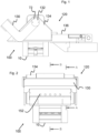
- a first side view of a sliding closure device 120 according to the invention of an embedding press 100 with closed closure lever 130 is shown.
- the closure lever 130 is mounted in a closure shaft 132, which is arranged on the top of the sliding carriage 134.
- the closure shaft 132 is covered on the outside by a rotating part 72.
- the sliding carriage 134 can be moved along the carriage carrier 136 and is in the use position, so that the embedding cylinder 10 is closed by the sliding closure 120.
- Fig.2 shows a front view of the Fig.1 shown sliding closure device 120 with closed locking lever 130.
- the cutting marks BB and AA show the cutting planes of the Fig.3 or 7.
- Suction openings 152 of the suction device 150 are arranged on the front side of the sliding carriage 134, in this example 5 suction openings arranged next to one another.
- Fig.3 shows the cutting plane BB from Fig.2 with the locking device 120 in the operating position and the locking lever 130 in the closed position.
- the upper piston 27 is engaged in the cylinder 10 so that the cylinder opening 12 (see eg Fig. 15 ) is closed.
- the locking shaft 132 runs transversely through the sliding carriage 134.
- a granulate compartment 1 for collecting excess granulate is arranged on the front side of the slide carrier 136.
- the sliding slide 134 When the sliding slide 134 is moved into the operating position, it automatically pushes excess granulate into it.
- a suction opening 152 is shown, which merges into a sliding carriage channel 154 within the sliding carriage 134.
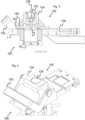
- Fig.4 shows a perspective schematic view of the locking device 120 in the closed position of the locking lever 130 as before.
- the upper piston cover 128 is flush with the top of the sliding carriage 134 in the closed position.
- Fig.5 shows a further perspective schematic view of the locking device 120, which keeps the cylinder 10 closed.
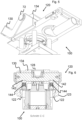
- Fig.6 shows another sectional view, the section being guided along a plane which is Fig.3 through the middle of the upper piston cover 128, the locking shaft 132 and the cylinder 10.
- the locking shaft 132 has a variable cross-section along its direction of extension.
- the locking shaft 132 has notches 142 into which spring elements 144 engage.
- the spring elements 144 generate a restoring force which, like a kind of "kneeling", holds the upper piston 27 and thus the locking lever 130 either in the closed position or in the open position.
- a carriage guide 122 is shown, which guides the sliding carriage 134 along its displacement direction (out of the plane of the sheet) on both sides of the cylinder 10.
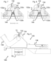
- Fig.7 finally shows a sectional view along the Fig.2 shown section line AA.
- the locking shaft 132 has two flattened areas 132a and 132b in this area of its extension. In between, the locking shaft 132 has a protuberance, i.e. a cam 132c.
- the flexible element 144 presses against the flattened area 132a and thus generates a holding force so that the locking shaft 132 remains in the closed position.
- the release force that must be applied to release the locking lever 130 from the closed position can be influenced or adjusted.
- the locking device 120 remains in the apex position in which the release force for disengaging the locking lever 130 from the closed position has just been applied or the locking lever 130 is pulled into the closed position when guided into the closed position by means of the now increasing holding force of the flexible element 144.
- the movement of the locking lever into the two end positions “open position” and “closed position” is thus “pulling and locking”.
- the locking shaft 132 By rotating the locking shaft 132 beyond the dead center, the locking device 120 and thus also the upper piston 27, which is directly connected to the locking device, are wedged.
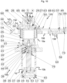
- FIG.10 is a side sectional view of an embedding press 100 with sliding closure device 120 in the operating position of the sliding carriage 134 and the closed position of the closure lever 130, in this example lever 60.
- the cylinder 10 is divided into a sample cylinder 10a and a pressure cylinder 10b and has a cylinder tube 53.
- the granulate compartment 1 is arranged on the front to accommodate excess granulate.
- the eccentric guide 4, together with the eccentric closure 5, defines a movement space 124 for the closure shaft 132, in this example realized by the eccentric bolt 66.
- a heating/cooling part 14 is arranged to the side of the pressing area for heating and cooling a sample (not shown) inserted into the cylinder 10.
- the heating/cooling part 14 surrounds the cylinder 10 in a ring shape.
- the heating/cooling part 14 is connected to the cylinder 10 by means of hose lines 34 (see e.g. Fig. 11 ) is supplied with water.
- a mold 63 is inserted into the sample cylinder, which has a certain diameter.
- the mold 63 is interchangeable in order to realize different sample diameters. In this example, a 50 mm mold 63 is used.
- the lower pressure cylinder 10b has a cylinder head 16 and a cylinder base 17.
- a piston 18 is movably arranged in the pressure cylinder 10b.
- the piston 18 is connected to the upper-lower piston 23 by means of a piston rod 19, so that a change in position of the piston 18 induces a change in position of the upper-lower piston 23.
- the upper piston 27, in this case a press piston 27, is positioned by the sliding closure 120 and blocked by the pressure built up in the sample cylinder 10a. Hydraulic fluid is supplied to or removed from the pressure cylinder 10b by means of the high-pressure hose 55, for example via the hydraulic opening 70.
- the locking lever 130 in this case a lever 60, can have a grip surface 46 to improve the haptics.
- a first position sensor 56 can be inserted into the carriage carrier 136, for example a proximity switch 56.
- the proximity switch 56 is designed in this example to detect whether the support plate 74 is retracted or extended, which means that the sliding carriage 134 can have assumed a service position (see e.g. Figs. 18 to 23 ). To assume the service position, the sliding carriage 134 on the carriage carrier 136 is moved completely in the direction of the swivel plate 59 and rotated about the axis 73 on the swivel plate 59.
- the position sensor 56 is implemented as an inductive proximity switch 56, e.g. in a design as a normally open contact.
- a cover plate 61 is inserted into the carriage carrier 136, which covers the suction connection channel 156 embedded in the carriage carrier.
- a suction cover 68 is attached to the sliding carriage 134.
- the operating position of the sliding carriage 134 is detected by a front position sensor 30, in particular it is an inductive position sensor 30.
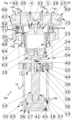
- Fig. 11 is the embodiment of the Fig.10 shown in a front sectional view, the same reference numerals represent the same objects.
- the sliding carriage 134 has assumed the insert position and the lever 60 has assumed the closed position.
- the carriage guide 122 is implemented by a sliding guide 64, which engages around the guide pins 123 of the sliding carriage 134 and thus implements a secure guidance of the sliding carriage 134 on the carriage carrier 136.
- the locking shaft 132 In the closed position, the locking shaft 132 has a notch 142 on the underside on both sides of the sample cylinder 10aje, into which a spring element 144, here a spring tensioner 71, engages.
- the heating/cooling part 14 is supplied with cooling water via the hose lines 34.
- Fig. 12 shows a schematic view of an embedding press 100 with sliding closure 120 in the operating position, in which the cylinder opening 11 (cf. e.g. Fig. 15 ) is completely closed.
- the sliding closure 120 is held in the closed position by the wedging of the upper piston 27 in the sample cylinder 10a and the pressure built up in the sample cylinder 10a.
- the sliding carriage 134 builds up pressure on the carriage guide 122 via the guide pins 123 if necessary and is thus held by the carriage carrier 136.
- the sliding carriage 134 can be moved along the carriage carrier 136 up to a rear end position at which the guide pins 123 no longer engage in the carriage guide 122, since the carriage guide 122 only extends over a part of the carriage carrier 136.
- the sliding carriage 134 In the rear end position, the sliding carriage 134 can then be pivoted about the pivot axis, whereby it is supported on the pivot plate 59. By means of the support plate 74, a locking in the service position can be achieved.
- Fig. 13 shows a side view of the embedding press 100, wherein the sliding closure is moved towards the rear end position, so that the cylinder opening (cf. eg Fig. 15 ) is released.
- a locking lever sensor 80 is integrated in the locking lever 130, which together with the second locking lever sensor 82 enables position detection of the locking lever 130.
- the locking lever sensor 80 can be used to query the closed position of the locking lever.
- Fig. 14 shows a front view of the same position of the sliding carriage 134.
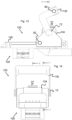
- FIG. 15 is a side sectional view of a section of the mounting press 100 shown with the sliding carriage in the Fig. 13 explained position.
- the embedding press 100 of the Fig. 15 The form shown has a suction device 150 which is ready for operation in the suction position of the sliding carriage 134 shown in the figure.
- the suction opening 152 is connected in a communicating manner via the sliding carriage channel to the suction connection channel 156 let into the cover 136 or carriage carrier 136.
- the suction air channel 158 is directly connected to the suction connection channel 156.
- Fig. 15 the cylinder axis 12.
- the granulate compartment 1 shown contains granulate residues 180 filled into it with the sliding carriage 134.
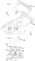
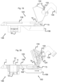
- FIG. 16 The suction position of the sliding carriage 134 is illustrated with a further perspective view.
- 5 suction openings 152 are incorporated into the front of the sliding carriage 134.
- the Fig. 17 illustrates the suction position of the sliding carriage 134 with yet another perspective view.
- the locking lever 130 with locking shaft 132 is shown in the open position.
- the flexible element 144 engages in the flattened area 132b of the locking shaft and thus exerts a holding force on the locking lever 130.
- the flexible element 144 In order to move the locking lever 130 from the open position to the closed position, the flexible element 144 must be in the plane of the drawing of the Fig. 18 be deflected downwards by applying force, wherein the force applied to the locking lever 130 is possibly amplified via the cam 132c of the locking shaft 132 and transmitted to the flexible element 144.
- FIG. 19 the service position of the sliding carriage 134 is illustrated, wherein the sliding carriage 134 is supported in the service position by means of the support plate 74 hinged in the carriage carrier 136.
- Fig. 20 shows a further embodiment of the embedding press 100 with a sliding carriage 134 in the service position, wherein in this embodiment the support plate 74 is hinged to the sliding carriage 134 and is supported in the recess in the carriage carrier 136. In this position the locking shaft 132 is completely retracted to one side in the movement space 124.
- the embedding press 100 is shown from the front with the closure device 120 in the service position, whereby the easy accessibility of the upper piston 27 from the underside is illustrated.
- An embodiment of the suction device 150 is also illustrated here.
- the suction openings 152 open into the sliding carriage channel 154. If the sliding carriage 134 is in the suction position, the opening on the underside of the sliding carriage channel 154 lies flush with the recess of the suction connection channel 156, so that a negative pressure generated on the underside can create suction at the suction openings 152 through the suction connection channel 156 and the sliding carriage channel 154.
- Fig. 22 shows a perspective view of the embodiment.
- Fig. 23 also shows the embedding press 100 with the locking device 120 in the service position in another perspective view. In the Figures 22 and 23 the front position sensor 30 is clearly shown, which detects the position of the sliding carriage 134 in the operating position.
- the embedding press 100 is shown in a side sectional view with the sliding carriage 134 in the suction position.
- the suction opening 152 opens into the sliding carriage channel 154, which in turn opens into the suction connection channel 156 embedded in the carriage carrier 136 in the suction position.
- An extraction air channel 158 is arranged underneath the extraction connection channel 156, which leads the exhaust air, possibly with vapors and/or dust, to a vacuum generator 160.
- An extraction filter 162 is arranged downstream behind the vacuum generator 160 in the exhaust air direction. This arrangement is advantageous, for example, if vapors are to be extracted using the extraction device 150.
- the extraction filter 162 can also be arranged at a suitable location, for example in the extraction air duct 158 and in front of the vacuum generator 160, for example if, in addition to dust, larger particles are to be expected in the extraction air and damage to the vacuum generator is thus avoided.
- FIG. 25 another embodiment of the embedding press 100 is shown with a sliding closure 120 in the closed position, wherein a Suction device 150 is implemented, which ensures suction even in the closed position and in particular during operation and heating of the embedding press.
- the suction opening 152 is arranged around the upper piston 27. If necessary, the front suction opening, which was in use in the suction position of the sliding carriage 134, is closed by a suction cover 155, which is advantageously arranged or attached to the locking lever 130.
- the locking lever 130 thus not only closes the embedding press 100 to start operation, but also the front suction openings 152, so that the suction effect for the operation of the embedding press 100 can be concentrated by the vacuum generator 160 on the area of the cylinder opening 11.
- the suction device 150 in the present embodiment is also able to absorb these influences and thus improve the application of the embedding press.
- FIG. 26 a further embodiment of the embedding press 100 with sliding closure 120 is shown, wherein suction openings 152 are introduced into the cover 136' or into the slide carrier 136.
- the suction openings are arranged concentrically around the cylinder opening 11.
- the suction effect at the suction openings 152 can be generated from below the cover 136' by means of a suction air duct 158 attached there.
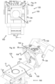
- Fig. 27 shows another embodiment of the embedding press 100, wherein a filling funnel 170 for filling granulate 180 is inserted into the cylinder opening 11.
- the filling funnel can be connected to the vacuum device 160 by means of the suction air channel 158 in order to remove dust directly during filling by means of a funnel.
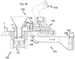
- a further embodiment of the embedding press 100 is shown with an inserted filling funnel 170 for filling granulate 180 into the cylinder opening 11, wherein the filling funnel is connected to the suction device 150.
- the suction opening 152' attached to the filling funnel which extends in a ring around the lower funnel opening of the filling funnel 170, is connected in a communicating manner to a funnel suction air channel 158'.
- the filling funnel 170 can now preferably be positioned so that the funnel suction air channel 158' is connected to the suction opening 152 present in the sliding carriage 134.
- the vacuum generating device 160 can thus advantageously also supply the filling funnel 170 with suction vacuum.
- FIG. 29 an embodiment of the modular embedding press system 106 with an internal embedding press 102 arranged in the basic module 101 and three external embedding presses 104 is shown in a rear view. All embedding presses 102, 104 have a sliding closure 120 and are arranged directly adjacent to one another.
- the base module 101 has three embedding press connectors 108 on the back for transmitting both the electrical power required by the external embedding presses 104 and control data for controlling the external embedding presses 104.
- the base module 101 also has a central power supply connection 110 for supplying all embedding presses 100, 102, 104 with electrical power from the external power supply, for example the public power supply network.
- the base module 101 also includes a cooling water inlet 112 and a cooling water return 114, which are supplied, for example, either by an external water supply or a circulation circuit with a heat exchanger.
- the modular embedding press system 106 has a water collection rail 116, 118 for connecting the embedding presses 102, 104.
- a central suction system 164 is provided, which can be controlled and regulated from the basic module 101.
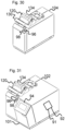
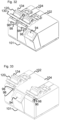
- Figs. 30 to 34 show different variants of the operation of the modular embedding press system.
- Fig. 30 shows a single external embedding press 104 for connection to a basic module 101 according to the invention.
- the external embedding press 104 has the sliding closure 120.
- the external embedding press 104 is equipped with an operating button 96 and a display device 98.
- Fig. 31 shows a basic module 101 with an internal embedding press 102.
- the basic module 101 has a central input device 94, with which the internal and external embedding presses 102, 104 can be programmed and controlled.
- the basic module also has an operating button 96 and a display device 98.
- the display device is implemented as a light ring 98, which is arranged around the operating button 96.
- the central control device 92 is also arranged in the basic module 101, which generates and outputs control parameters for the internal and external embedding presses 102, 104.
- a power distributor 91 is also arranged in the basic module 101, by means of which distributes the electrical power provided by the base module 101 to the internal and external embedding presses 102, 104.
- Fig. 32 shows a modular embedding press system 106 with an internal embedding press 102 and an external embedding press 104. Both embedding presses 102, 104 are equipped with the sliding lock 120 as well as an operating button 96 and a display device 98.
- the base module 101 also has a central input device 94 for programming and controlling all embedding presses 102, 104 connected to the base module.
- Fig. 33 shows another alternative arrangement of the modular mounting press system 106 with an internal mounting press 102 and an external mounting press 104.
- Fig. 34 finally shows a modular embedding press system 106 with an internal embedding press 102 and three external embedding presses 104, each of which is controlled and programmed by the base module 101 and supplied with electrical power by the base module 101.
- the respective embedding presses 102, 104 can be designed identically to one another. But the respective embedding presses 102, 104 can also be designed differently with regard to the closure system 120 or the suction device 150. With this system, it is also easy, for example, to provide different press molds 63 in the embedding presses 102, 104, so that different embedding presses 102, 104 can be used for different sample diameters without having to change the press mold 63.
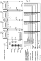
- Fig. 35 shows a simple flow chart for the modular embedding press system 106.
- a process starts.
- the start of the process can mean that one or more embedding presses 102, 104 of the modular embedding press system 106 are already in operation and the user has activated another embedding press 102, 104 via the central input device 94.
- the basic module 101 has the central control device 92, by means of which the embedding presses 102, 104 are controlled.
- the control device 92 now checks in step 204, for example based on the data provided by the power distributor 91, which number of embedding presses 102, 104 are to be supplied with electrical power by the basic module 101.
- prioritization with regard to power distribution is only carried out when 4 or more embedding units 102, 104 are in operation. If fewer than 4 embedding units 102, 104 are connected or in operation, no prioritization of the power distribution is required in this example and the flow chart jumps to step 220 end.
- the flow chart is based on the idea that in the case of a Parallel operation of 3 or fewer embedding units provides sufficient power for simultaneous full operation of all embedding units 102, 104.
- step 206 is whether all at least 4 heating and cooling parts 14 of the at least 4 embedding units 102, 104 are to be supplied with energy. If not all heating and cooling parts 14 are operated in parallel, the flow chart returns to a loop in which the status of the embedding units is regularly checked in step 206.
- the prioritization sequence is determined in step 208 depending on the mode of the embedding units (heating or holding) and the control deviation of the temperatures.
- the power distribution is determined, in this example blocking the heating part of the embedding unit 102, 104 with the lowest priority. This query is also carried out cyclically as long as the conflicting parallel operation of more than 3 embedding units 102, 104 takes place.
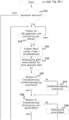
- FIG. 36 A flow chart for a filling assistant is shown.
- the program sequence is started in step 230 and in step 232 it is first checked whether the assistant is activated. If this is not the case, the flow chart aborts and ends at step 260.
- step 234 the query is made in step 234 whether the button 96 on an embedding unit 102, 104 was pressed and a closure 120 was opened.
- the assistant expects the selection of an embedding unit 102, 104, in particular by means of the control button 96 on the embedding unit 102, 104, in order to continue with the further process.
- step 236 touch/switch operation
- step 238 the suction on the selected embedding unit 102, 104, or the central suction 164, is automatically activated for a predefinable period of time.
- Step 240 checks whether the corresponding button for an inverted piston movement is activated in the visualization. If an inverted piston movement is desired, the piston movement is reversed in step 242.
- Step 244 checks whether an extraction switch has been defined in the visualization. If this is the case, the extraction is switched in step 246.
- step 248 the position sensors (or position sensors) 30, 56, 80, 82 are queried with regard to the closed position of the sliding closure 120 of the selected embedding unit 102, 104. If it is determined that the closure 120 is completely closed, the embedding can be started in step 250.
- step 252 After completion of the embedding process with the selected embedding unit 102, 104, a query is made in step 252 as to whether the closure can be opened. If this is the case, the piston 23 is raised in step 254 and the filling assistant is terminated in step 260.
- the present invention enables comfortable, rapid and safe operation of an embedding press 100, 102, 104 with a suction device and the improvement of work safety through the integrated suction of dust and/or vapors of an embedding press 100, 102, 104.
- an embedding press 100, 102, 104 with the suction device 150 according to the invention can be operated more comfortably and quickly while maintaining the same level of safety. Breaks during processing for venting and removing dust clouds are no longer necessary.
- the invention can also be combined with a sliding closure and/or integrated into a modular embedding press system.
- the sliding closure 120 thus enables convenient access to the upper piston 27 arranged in the sliding closure 120, which can, for example, be easily cleaned or replaced.
- an embedding press 100, 102, 104 according to the above aspect is disclosed, wherein the suction device 150 is at least partially built into the sliding carriage 134 or wherein the extracted granulate dust 180 and/or vapors are passed through the sliding carriage.
- an embedding press 100, 102, 104 according to any of the preceding aspects is disclosed, wherein the suction device 150 has suction openings 152 in the cover plate arranged around the cylinder opening 11 recessed in the cover plate 136, 136 ⁇ .
- an embedding press 100, 102, 104 according to any of the preceding aspects is disclosed, Furthermore, with a vacuum generator 160 arranged on the embedding press to provide the suction effect.
- an embedding press 100, 102, 104 according to any of the preceding aspects is disclosed, further comprising a front-side granulate compartment 1 for receiving granulate residues 180 that cannot pass through the suction opening, wherein in particular the granulate residues can be moved from the sliding carriage 134 into the granulate compartment by pushing the sliding carriage onto the cylinder opening 11 before using the embedding press.
- a suction device 150 according to the above aspect is disclosed, wherein the suction device is designed to exert the suction effect directly in the region of the cylinder opening 11 of the embedding cylinder 10.
- a suction device 150 according to one of the preceding aspects is disclosed, wherein the cover 136, 136 ⁇ is a cover plate and has a slide guide 122 for a sliding slide 134.
- a suction device 150 according to one of the preceding aspects is disclosed, wherein at least a portion of the extraction air duct 158 is recessed into the cover plate 136, 136', so that the extraction air duct passes through the cover plate and/or at least a portion passes through the cover plate.
- a suction device 150 according to one of the preceding aspects is disclosed, further comprising a filter element 162 arranged at the vacuum generator 160.
Landscapes
- Life Sciences & Earth Sciences (AREA)
- Health & Medical Sciences (AREA)
- Immunology (AREA)
- Chemical & Material Sciences (AREA)
- Analytical Chemistry (AREA)
- Biochemistry (AREA)
- General Health & Medical Sciences (AREA)
- General Physics & Mathematics (AREA)
- Physics & Mathematics (AREA)
- Pathology (AREA)
- Engineering & Computer Science (AREA)
- Mechanical Engineering (AREA)
- Biomedical Technology (AREA)
- Molecular Biology (AREA)
- Sampling And Sample Adjustment (AREA)
- Automatic Assembly (AREA)
- Powder Metallurgy (AREA)
- Investigating And Analyzing Materials By Characteristic Methods (AREA)
- Cleaning In General (AREA)
Applications Claiming Priority (3)
| Application Number | Priority Date | Filing Date | Title |
|---|---|---|---|
| DE102017109677.9A DE102017109677A1 (de) | 2017-05-05 | 2017-05-05 | Einbettpresse, Absaugeinrichtung für eine Einbettpresse und modulares Einbettpressensystem |
| PCT/EP2018/056037 WO2018202342A1 (fr) | 2017-05-05 | 2018-03-12 | Presse d'enrobage, dispositif d'aspiration pour presse d'enrobage et système de presse d'enrobage modulaire |
| EP18710861.8A EP3619515B1 (fr) | 2017-05-05 | 2018-03-12 | Presse d'enrobage, dispositif d'aspiration pour presse d'enrobage et système de presse d'enrobage modulaire |
Related Parent Applications (2)
| Application Number | Title | Priority Date | Filing Date |
|---|---|---|---|
| EP18710861.8A Division EP3619515B1 (fr) | 2017-05-05 | 2018-03-12 | Presse d'enrobage, dispositif d'aspiration pour presse d'enrobage et système de presse d'enrobage modulaire |
| EP18710861.8A Division-Into EP3619515B1 (fr) | 2017-05-05 | 2018-03-12 | Presse d'enrobage, dispositif d'aspiration pour presse d'enrobage et système de presse d'enrobage modulaire |
Publications (3)
| Publication Number | Publication Date |
|---|---|
| EP4403328A2 true EP4403328A2 (fr) | 2024-07-24 |
| EP4403328A3 EP4403328A3 (fr) | 2024-10-09 |
| EP4403328B1 EP4403328B1 (fr) | 2026-07-29 |
Family
ID=61627117
Family Applications (2)
| Application Number | Title | Priority Date | Filing Date |
|---|---|---|---|
| EP24179899.0A Active EP4403328B1 (fr) | 2017-05-05 | 2018-03-12 | Système de presse d'enrobage modulaire |
| EP18710861.8A Active EP3619515B1 (fr) | 2017-05-05 | 2018-03-12 | Presse d'enrobage, dispositif d'aspiration pour presse d'enrobage et système de presse d'enrobage modulaire |
Family Applications After (1)
| Application Number | Title | Priority Date | Filing Date |
|---|---|---|---|
| EP18710861.8A Active EP3619515B1 (fr) | 2017-05-05 | 2018-03-12 | Presse d'enrobage, dispositif d'aspiration pour presse d'enrobage et système de presse d'enrobage modulaire |
Country Status (6)
| Country | Link |
|---|---|
| US (2) | US11685084B2 (fr) |
| EP (2) | EP4403328B1 (fr) |
| JP (3) | JP6957643B2 (fr) |
| CN (2) | CN115014889A (fr) |
| DE (1) | DE102017109677A1 (fr) |
| WO (1) | WO2018202342A1 (fr) |
Families Citing this family (2)
| Publication number | Priority date | Publication date | Assignee | Title |
|---|---|---|---|---|
| DE102017109677A1 (de) | 2017-05-05 | 2018-11-08 | Atm Gmbh | Einbettpresse, Absaugeinrichtung für eine Einbettpresse und modulares Einbettpressensystem |
| CN116158789A (zh) * | 2023-03-16 | 2023-05-26 | 湖南省华芯医疗器械有限公司 | 一种取样盖、样本容器及取样装置 |
Citations (1)
| Publication number | Priority date | Publication date | Assignee | Title |
|---|---|---|---|---|
| WO2018202342A1 (fr) | 2017-05-05 | 2018-11-08 | Atm Gmbh | Presse d'enrobage, dispositif d'aspiration pour presse d'enrobage et système de presse d'enrobage modulaire |
Family Cites Families (33)
| Publication number | Priority date | Publication date | Assignee | Title |
|---|---|---|---|---|
| US4473215A (en) * | 1982-01-12 | 1984-09-25 | Industrial Electronic Rubber Company | Control apparatus for molding presses |
| JPS59135896U (ja) | 1983-02-23 | 1984-09-11 | 三菱重工業株式会社 | 試料埋込プレス |
| US4966538A (en) * | 1988-06-01 | 1990-10-30 | Buehler, Ltd. | Mounting press |
| US4969505A (en) | 1989-12-21 | 1990-11-13 | General Motors Corporation | Vacuum bore chill for lost foam casting |
| DE69129412T2 (de) * | 1990-03-22 | 1998-09-03 | Fanuc Ltd | Spritzgiessmaschine vom typ mit automatischem formwechsel |
| JPH1012578A (ja) * | 1996-06-26 | 1998-01-16 | Mitsubishi Electric Corp | ウエハ・支持基板貼付け方法,及びウエハ・支持基板貼付け装置 |
| US7188001B2 (en) * | 1998-03-23 | 2007-03-06 | Cepheid | System and method for temperature control |
| GB2363632B (en) | 2000-02-21 | 2003-12-10 | Larry R Russell | Seal assembly its use and installation |
| JP2001314940A (ja) | 2000-05-08 | 2001-11-13 | Sintokogio Ltd | 鋳型造型方法およびその装置 |
| US6854964B1 (en) * | 2000-09-05 | 2005-02-15 | Imperial Custom Molding, Inc. | Apparatus for molding a plate |
| CN2482071Y (zh) * | 2001-06-25 | 2002-03-13 | 葛炎 | 自动镶嵌机 |
| CN2723186Y (zh) | 2004-09-07 | 2005-09-07 | 董建国 | 超声波镶嵌机 |
| US20070090554A1 (en) * | 2005-10-26 | 2007-04-26 | Rick Wykoff | Panel molding method and apparatus |
| JP4691641B2 (ja) | 2005-12-07 | 2011-06-01 | 独立行政法人交通安全環境研究所 | 信号冒進警報装置および車載機 |
| EP2070454B1 (fr) * | 2007-12-12 | 2015-07-15 | Nestec S.A. | Fabrication modulaire de machines de production de boissons |
| US8141731B2 (en) | 2008-05-27 | 2012-03-27 | Seaquist Closures L.L.C. | Closure with lid and slidable latch system |
| JP5323571B2 (ja) * | 2009-04-17 | 2013-10-23 | 株式会社菊水製作所 | 粉体圧縮成形機 |
| JP5644017B2 (ja) * | 2010-01-20 | 2014-12-24 | 曙ブレーキ工業株式会社 | 樹脂ピストンの成形方法及び樹脂ピストンの製造方法 |
| JP2011161776A (ja) | 2010-02-09 | 2011-08-25 | Dragonjet Corp | 樹脂成形補助システム |
| JP5704944B2 (ja) | 2011-02-03 | 2015-04-22 | 富士機械製造株式会社 | 基板作業装置 |
| DE102012200217B4 (de) | 2012-01-09 | 2015-01-08 | Danfoss Power Solutions Gmbh & Co. Ohg | Neutraleinstellungsvorrichtung einer verstellbaren Hydraulikmaschine |
| US9645058B2 (en) * | 2012-07-17 | 2017-05-09 | Illinois Tool Works Inc. | Sample encapsulation system and method |
| CN202814774U (zh) * | 2012-10-08 | 2013-03-20 | 莱州市蔚仪试验器械制造有限公司 | 自动镶嵌机 |
| EP3091883B1 (fr) | 2014-01-10 | 2017-10-11 | Koninklijke Philips N.V. | Support de filtre pour machines de production de boisson |
| TWI566876B (zh) | 2014-06-06 | 2017-01-21 | Inclusion device | |
| CN105223063B (zh) | 2014-06-18 | 2017-11-07 | 科利达科技企业股份有限公司 | 镶埋机的封闭装置 |
| JP2016045044A (ja) | 2014-08-21 | 2016-04-04 | 株式会社フューチュアテック | 埋込機及び硬度評価用の試料の埋込方法 |
| JP6491464B2 (ja) * | 2014-11-28 | 2019-03-27 | Towa株式会社 | 成形品製造装置及び成形品製造方法 |
| JP6491508B2 (ja) | 2015-03-23 | 2019-03-27 | Towa株式会社 | 樹脂封止装置及び樹脂成形品の製造方法 |
| NL2014802B1 (en) | 2015-05-13 | 2016-12-30 | Besi Netherlands Bv | Modular system for moulding electronic components and kit-of-parts for assembling such a modular system. |
| JP5977420B1 (ja) * | 2015-11-05 | 2016-08-24 | 濠▲瑩▼機械企業有限公司 | パウダー成形機 |
| CN105965916A (zh) * | 2016-06-02 | 2016-09-28 | 山东中航泰达复合材料股份有限公司 | 一种复合材料成型设备及其用于复合材成型的工艺 |
| DE102017109676A1 (de) * | 2017-05-05 | 2018-11-08 | Atm Gmbh | Einbettpresse und Verschlusseinrichtung für eine Einbettpresse |
-
2017
- 2017-05-05 DE DE102017109677.9A patent/DE102017109677A1/de active Pending
-
2018
- 2018-03-12 EP EP24179899.0A patent/EP4403328B1/fr active Active
- 2018-03-12 CN CN202210518833.1A patent/CN115014889A/zh active Pending
- 2018-03-12 US US16/610,686 patent/US11685084B2/en active Active
- 2018-03-12 CN CN201880029853.4A patent/CN110637220B/zh active Active
- 2018-03-12 JP JP2019560305A patent/JP6957643B2/ja active Active
- 2018-03-12 EP EP18710861.8A patent/EP3619515B1/fr active Active
- 2018-03-12 WO PCT/EP2018/056037 patent/WO2018202342A1/fr not_active Ceased
-
2021
- 2021-10-06 JP JP2021164695A patent/JP2022008893A/ja active Pending
-
2023
- 2023-04-28 JP JP2023073944A patent/JP7536139B2/ja active Active
- 2023-05-08 US US18/313,398 patent/US12251859B2/en active Active
Patent Citations (1)
| Publication number | Priority date | Publication date | Assignee | Title |
|---|---|---|---|---|
| WO2018202342A1 (fr) | 2017-05-05 | 2018-11-08 | Atm Gmbh | Presse d'enrobage, dispositif d'aspiration pour presse d'enrobage et système de presse d'enrobage modulaire |
Also Published As
| Publication number | Publication date |
|---|---|
| EP4403328A3 (fr) | 2024-10-09 |
| US11685084B2 (en) | 2023-06-27 |
| JP6957643B2 (ja) | 2021-11-02 |
| EP3619515B1 (fr) | 2024-07-24 |
| US20230339151A1 (en) | 2023-10-26 |
| JP2022008893A (ja) | 2022-01-14 |
| EP3619515A1 (fr) | 2020-03-11 |
| WO2018202342A1 (fr) | 2018-11-08 |
| CN110637220B (zh) | 2022-05-27 |
| CN110637220A (zh) | 2019-12-31 |
| US12251859B2 (en) | 2025-03-18 |
| EP4403328B1 (fr) | 2026-07-29 |
| US20210154893A1 (en) | 2021-05-27 |
| DE102017109677A1 (de) | 2018-11-08 |
| JP2023100779A (ja) | 2023-07-19 |
| EP3619515C0 (fr) | 2024-07-24 |
| CN115014889A (zh) | 2022-09-06 |
| JP7536139B2 (ja) | 2024-08-19 |
| JP2020519755A (ja) | 2020-07-02 |
Similar Documents
| Publication | Publication Date | Title |
|---|---|---|
| DE102012213824B4 (de) | Messerhalter mit Klingenwechselvorrichtung | |
| DE102008000262B4 (de) | Vorrichtung und Verfahren zum Filtern von in einem Luftstrom befindlichen Schnittabfällen eines Mikrotoms | |
| DE112010003790B4 (de) | Leicht entfernbares Verbrennungsrohr | |
| WO2018002254A1 (fr) | Tête de dosage, dispositif de dosage comprenant une tête de dosage et procédé de dosage au moyen d'une tête de dosage | |
| DE102012105461B4 (de) | Ballenpresse | |
| EP3619516B1 (fr) | Presse d'enrobage et système de fermeture pour presse d'enrobage | |
| DE19963141A1 (de) | Pipette für ein Pipettiersystem | |
| EP3388767B1 (fr) | Appareil de traitement dentaire | |
| EP3619515B1 (fr) | Presse d'enrobage, dispositif d'aspiration pour presse d'enrobage et système de presse d'enrobage modulaire | |
| DE69208685T2 (de) | Vorrichtung zum sammeln von abfall,insbesondere von glasverpackungen | |
| DE102006026793A1 (de) | Presseinrichtung, insbesondere zum Entfeuchten von Metallspäne oder Schleifschlamm | |
| DE10009403B4 (de) | Vorrichtung zum Verformen von thermoplastischen Materialien | |
| DE102010031011A1 (de) | Vorrichtung zum Herstellen eines Fleischproduktes und zur Verwendung in der Vorrichtung geeigneter Formbehälter | |
| EP0487493B1 (fr) | Dispositif automatique pour enlever des bouchons pour récipients | |
| EP0154282A2 (fr) | Dispositif pour prélèvement d'échantillons | |
| EP0778064A2 (fr) | Dispositif filtrant et procédé de filtration | |
| DE102020129511A1 (de) | Vorrichtung zum Zerkleinern von Abfällen | |
| DE3602479C2 (fr) | ||
| EP0487491B1 (fr) | Dispositif à porteuse intermédiaire | |
| DE102018202001A1 (de) | Schneidvorrichtung zum Schneiden von Nahrungsmitteln in Schnittgut | |
| WO1997044670A1 (fr) | Appareil automatique de pipettage | |
| DE20213111U1 (de) | Vorrichtung zum Aufnehmen und Ablegen von flächigen Teilen mit textiler Oberfläche, beispielsweise Fußmatten | |
| CH651741A5 (de) | Kaffeemaschine. | |
| DE3221489A1 (de) | Automatische biegevorrichtung | |
| EP1660239A1 (fr) | Systeme pour remplir des contenants de stockage a partir d'appareils de distribution |
Legal Events
| Date | Code | Title | Description |
|---|---|---|---|
| PUAI | Public reference made under article 153(3) epc to a published international application that has entered the european phase |
Free format text: ORIGINAL CODE: 0009012 |
|
| STAA | Information on the status of an ep patent application or granted ep patent |
Free format text: STATUS: THE APPLICATION HAS BEEN PUBLISHED |
|
| AC | Divisional application: reference to earlier application |
Ref document number: 3619515 Country of ref document: EP Kind code of ref document: P |
|
| AK | Designated contracting states |
Kind code of ref document: A2 Designated state(s): AL AT BE BG CH CY CZ DE DK EE ES FI FR GB GR HR HU IE IS IT LI LT LU LV MC MK MT NL NO PL PT RO RS SE SI SK SM TR |
|
| REG | Reference to a national code |
Ref country code: DE Ref legal event code: R079 Free format text: PREVIOUS MAIN CLASS: B29C0043360000 Ipc: G01N0001280000 Ref document number: 502018016687 Country of ref document: DE |
|
| PUAL | Search report despatched |
Free format text: ORIGINAL CODE: 0009013 |
|
| AK | Designated contracting states |
Kind code of ref document: A3 Designated state(s): AL AT BE BG CH CY CZ DE DK EE ES FI FR GB GR HR HU IE IS IT LI LT LU LV MC MK MT NL NO PL PT RO RS SE SI SK SM TR |
|
| RIC1 | Information provided on ipc code assigned before grant |
Ipc: B29C 43/36 20060101ALI20240903BHEP Ipc: G01N 1/36 20060101ALI20240903BHEP Ipc: B29C 43/56 20060101ALI20240903BHEP Ipc: G01N 1/28 20060101AFI20240903BHEP |
|
| STAA | Information on the status of an ep patent application or granted ep patent |
Free format text: STATUS: REQUEST FOR EXAMINATION WAS MADE |
|
| 17P | Request for examination filed |
Effective date: 20250331 |
|
| GRAP | Despatch of communication of intention to grant a patent |
Free format text: ORIGINAL CODE: EPIDOSNIGR1 |
|
| STAA | Information on the status of an ep patent application or granted ep patent |
Free format text: STATUS: GRANT OF PATENT IS INTENDED |
|
| RIC1 | Information provided on ipc code assigned before grant |
Ipc: G01N 1/28 20060101AFI20260226BHEP Ipc: B29C 43/56 20060101ALI20260226BHEP Ipc: G01N 1/36 20060101ALI20260226BHEP Ipc: B29C 43/36 20060101ALI20260226BHEP |
|
| INTG | Intention to grant announced |
Effective date: 20260306 |
|
| GRAS | Grant fee paid |
Free format text: ORIGINAL CODE: EPIDOSNIGR3 |
|
| GRAA | (expected) grant |
Free format text: ORIGINAL CODE: 0009210 |
|
| STAA | Information on the status of an ep patent application or granted ep patent |
Free format text: STATUS: THE PATENT HAS BEEN GRANTED |
|
| AC | Divisional application: reference to earlier application |
Ref document number: 3619515 Country of ref document: EP Kind code of ref document: P |
|
| AK | Designated contracting states |
Kind code of ref document: B1 Designated state(s): AL AT BE BG CH CY CZ DE DK EE ES FI FR GB GR HR HU IE IS IT LI LT LU LV MC MK MT NL NO PL PT RO RS SE SI SK SM TR |
|
| REG | Reference to a national code |
Ref country code: CH Ref legal event code: F10 Free format text: ST27 STATUS EVENT CODE: U-0-0-F10-F00 (AS PROVIDED BY THE NATIONAL OFFICE) Effective date: 20260729 |
|
| REG | Reference to a national code |
Ref country code: DE Ref legal event code: R096 Ref document number: 502018016687 Country of ref document: DE |