EP4398024A1 - Elektronische vorrichtung - Google Patents
Elektronische vorrichtung Download PDFInfo
- Publication number
- EP4398024A1 EP4398024A1 EP23215763.6A EP23215763A EP4398024A1 EP 4398024 A1 EP4398024 A1 EP 4398024A1 EP 23215763 A EP23215763 A EP 23215763A EP 4398024 A1 EP4398024 A1 EP 4398024A1
- Authority
- EP
- European Patent Office
- Prior art keywords
- optical modulation
- substrate
- modulation region
- support member
- electronic device
- Prior art date
- Legal status (The legal status is an assumption and is not a legal conclusion. Google has not performed a legal analysis and makes no representation as to the accuracy of the status listed.)
- Granted
Links
Images


Classifications
-
- G—PHYSICS
- G02—OPTICS
- G02F—OPTICAL DEVICES OR ARRANGEMENTS FOR THE CONTROL OF LIGHT BY MODIFICATION OF THE OPTICAL PROPERTIES OF THE MEDIA OF THE ELEMENTS INVOLVED THEREIN; NON-LINEAR OPTICS; FREQUENCY-CHANGING OF LIGHT; OPTICAL LOGIC ELEMENTS; OPTICAL ANALOGUE/DIGITAL CONVERTERS
- G02F1/00—Devices or arrangements for the control of the intensity, colour, phase, polarisation or direction of light arriving from an independent light source, e.g. switching, gating or modulating; Non-linear optics
- G02F1/01—Devices or arrangements for the control of the intensity, colour, phase, polarisation or direction of light arriving from an independent light source, e.g. switching, gating or modulating; Non-linear optics for the control of the intensity, phase, polarisation or colour
- G02F1/13—Devices or arrangements for the control of the intensity, colour, phase, polarisation or direction of light arriving from an independent light source, e.g. switching, gating or modulating; Non-linear optics for the control of the intensity, phase, polarisation or colour based on liquid crystals, e.g. single liquid crystal display cells
- G02F1/133—Constructional arrangements; Operation of liquid crystal cells; Circuit arrangements
- G02F1/1333—Constructional arrangements; Manufacturing methods
- G02F1/133371—Cells with varying thickness of the liquid crystal layer
-
- G—PHYSICS
- G02—OPTICS
- G02B—OPTICAL ELEMENTS, SYSTEMS OR APPARATUS
- G02B27/00—Optical systems or apparatus not provided for by any of the groups G02B1/00 - G02B26/00, G02B30/00
- G02B27/01—Head-up displays
- G02B27/017—Head mounted
- G02B27/0172—Head mounted characterised by optical features
-
- G—PHYSICS
- G02—OPTICS
- G02F—OPTICAL DEVICES OR ARRANGEMENTS FOR THE CONTROL OF LIGHT BY MODIFICATION OF THE OPTICAL PROPERTIES OF THE MEDIA OF THE ELEMENTS INVOLVED THEREIN; NON-LINEAR OPTICS; FREQUENCY-CHANGING OF LIGHT; OPTICAL LOGIC ELEMENTS; OPTICAL ANALOGUE/DIGITAL CONVERTERS
- G02F1/00—Devices or arrangements for the control of the intensity, colour, phase, polarisation or direction of light arriving from an independent light source, e.g. switching, gating or modulating; Non-linear optics
- G02F1/01—Devices or arrangements for the control of the intensity, colour, phase, polarisation or direction of light arriving from an independent light source, e.g. switching, gating or modulating; Non-linear optics for the control of the intensity, phase, polarisation or colour
- G02F1/0102—Constructional details, not otherwise provided for in this subclass
-
- G—PHYSICS
- G02—OPTICS
- G02B—OPTICAL ELEMENTS, SYSTEMS OR APPARATUS
- G02B27/00—Optical systems or apparatus not provided for by any of the groups G02B1/00 - G02B26/00, G02B30/00
- G02B27/01—Head-up displays
- G02B27/0189—Sight systems
-
- G—PHYSICS
- G02—OPTICS
- G02C—SPECTACLES; SUNGLASSES OR GOGGLES INSOFAR AS THEY HAVE THE SAME FEATURES AS SPECTACLES; CONTACT LENSES
- G02C7/00—Optical parts
- G02C7/02—Lenses; Lens systems ; Methods of designing lenses
- G02C7/08—Auxiliary lenses; Arrangements for varying focal length
- G02C7/081—Ophthalmic lenses with variable focal length
- G02C7/083—Electrooptic lenses
-
- G—PHYSICS
- G02—OPTICS
- G02F—OPTICAL DEVICES OR ARRANGEMENTS FOR THE CONTROL OF LIGHT BY MODIFICATION OF THE OPTICAL PROPERTIES OF THE MEDIA OF THE ELEMENTS INVOLVED THEREIN; NON-LINEAR OPTICS; FREQUENCY-CHANGING OF LIGHT; OPTICAL LOGIC ELEMENTS; OPTICAL ANALOGUE/DIGITAL CONVERTERS
- G02F1/00—Devices or arrangements for the control of the intensity, colour, phase, polarisation or direction of light arriving from an independent light source, e.g. switching, gating or modulating; Non-linear optics
- G02F1/0009—Materials therefor
- G02F1/0045—Liquid crystals characterised by their physical properties
-
- G—PHYSICS
- G02—OPTICS
- G02F—OPTICAL DEVICES OR ARRANGEMENTS FOR THE CONTROL OF LIGHT BY MODIFICATION OF THE OPTICAL PROPERTIES OF THE MEDIA OF THE ELEMENTS INVOLVED THEREIN; NON-LINEAR OPTICS; FREQUENCY-CHANGING OF LIGHT; OPTICAL LOGIC ELEMENTS; OPTICAL ANALOGUE/DIGITAL CONVERTERS
- G02F1/00—Devices or arrangements for the control of the intensity, colour, phase, polarisation or direction of light arriving from an independent light source, e.g. switching, gating or modulating; Non-linear optics
- G02F1/01—Devices or arrangements for the control of the intensity, colour, phase, polarisation or direction of light arriving from an independent light source, e.g. switching, gating or modulating; Non-linear optics for the control of the intensity, phase, polarisation or colour
- G02F1/13—Devices or arrangements for the control of the intensity, colour, phase, polarisation or direction of light arriving from an independent light source, e.g. switching, gating or modulating; Non-linear optics for the control of the intensity, phase, polarisation or colour based on liquid crystals, e.g. single liquid crystal display cells
- G02F1/133—Constructional arrangements; Operation of liquid crystal cells; Circuit arrangements
- G02F1/1333—Constructional arrangements; Manufacturing methods
- G02F1/133368—Cells having two substrates with different characteristics, e.g. different thickness or material
-
- G—PHYSICS
- G02—OPTICS
- G02F—OPTICAL DEVICES OR ARRANGEMENTS FOR THE CONTROL OF LIGHT BY MODIFICATION OF THE OPTICAL PROPERTIES OF THE MEDIA OF THE ELEMENTS INVOLVED THEREIN; NON-LINEAR OPTICS; FREQUENCY-CHANGING OF LIGHT; OPTICAL LOGIC ELEMENTS; OPTICAL ANALOGUE/DIGITAL CONVERTERS
- G02F1/00—Devices or arrangements for the control of the intensity, colour, phase, polarisation or direction of light arriving from an independent light source, e.g. switching, gating or modulating; Non-linear optics
- G02F1/01—Devices or arrangements for the control of the intensity, colour, phase, polarisation or direction of light arriving from an independent light source, e.g. switching, gating or modulating; Non-linear optics for the control of the intensity, phase, polarisation or colour
- G02F1/13—Devices or arrangements for the control of the intensity, colour, phase, polarisation or direction of light arriving from an independent light source, e.g. switching, gating or modulating; Non-linear optics for the control of the intensity, phase, polarisation or colour based on liquid crystals, e.g. single liquid crystal display cells
- G02F1/133—Constructional arrangements; Operation of liquid crystal cells; Circuit arrangements
- G02F1/1333—Constructional arrangements; Manufacturing methods
- G02F1/1339—Gaskets; Spacers; Sealing of cells
- G02F1/13396—Spacers having different sizes
-
- G—PHYSICS
- G02—OPTICS
- G02F—OPTICAL DEVICES OR ARRANGEMENTS FOR THE CONTROL OF LIGHT BY MODIFICATION OF THE OPTICAL PROPERTIES OF THE MEDIA OF THE ELEMENTS INVOLVED THEREIN; NON-LINEAR OPTICS; FREQUENCY-CHANGING OF LIGHT; OPTICAL LOGIC ELEMENTS; OPTICAL ANALOGUE/DIGITAL CONVERTERS
- G02F1/00—Devices or arrangements for the control of the intensity, colour, phase, polarisation or direction of light arriving from an independent light source, e.g. switching, gating or modulating; Non-linear optics
- G02F1/29—Devices or arrangements for the control of the intensity, colour, phase, polarisation or direction of light arriving from an independent light source, e.g. switching, gating or modulating; Non-linear optics for the control of the position or the direction of light beams, i.e. deflection
- G02F1/294—Variable focal length devices
-
- G—PHYSICS
- G02—OPTICS
- G02F—OPTICAL DEVICES OR ARRANGEMENTS FOR THE CONTROL OF LIGHT BY MODIFICATION OF THE OPTICAL PROPERTIES OF THE MEDIA OF THE ELEMENTS INVOLVED THEREIN; NON-LINEAR OPTICS; FREQUENCY-CHANGING OF LIGHT; OPTICAL LOGIC ELEMENTS; OPTICAL ANALOGUE/DIGITAL CONVERTERS
- G02F1/00—Devices or arrangements for the control of the intensity, colour, phase, polarisation or direction of light arriving from an independent light source, e.g. switching, gating or modulating; Non-linear optics
- G02F1/35—Non-linear optics
- G02F1/3515—All-optical modulation, gating, switching, e.g. control of a light beam by another light beam
-
- G—PHYSICS
- G02—OPTICS
- G02B—OPTICAL ELEMENTS, SYSTEMS OR APPARATUS
- G02B27/00—Optical systems or apparatus not provided for by any of the groups G02B1/00 - G02B26/00, G02B30/00
- G02B27/01—Head-up displays
- G02B27/017—Head mounted
- G02B2027/0178—Eyeglass type
Definitions
- a pair of smart glasses is an electronic device capable of changing a focal length according to actual needs. Specifically, a pair of smart glasses is able to adjust a refractive power of lenses through changing voltages to control a medium layer.
- a range of the adjustable refractive power is subject to a cell gap. In order to increase the range of the adjustable refractive power, a height of the spacer should be increased to expand the cell gap, while there are still a number of problems to be solved.
- an electronic device that has an optical modulation region and a non-optical modulation region
- the electronic device includes a first substrate, a first transparent electrode layer, and a second transparent electrode layer.
- the first transparent electrode layer is disposed on the first substrate.
- the second transparent electrode layer is disposed on the first transparent electrode layer and has an opening.
- the optical modulation region overlaps the opening, and the non-optical modulation region overlaps the first transparent electrode layer and the second transparent electrode layer.
- a cell gap of the optical modulation region is greater than a cell gap of the non-optical modulation region.
- terminologies are used throughout the description and the appended claims to refer to specific elements. As to be understood by those skilled in the art, electronic device manufacturers may refer to an element by different names. Herein, it is not intended to distinguish between elements that have different names instead of different functions.
- terminologies such as “include”, “comprise”, and “have” are used in an open-ended manner, and thus should be interpreted as “including, but not limited to”. Therefore, the terminologies "include”, “comprise”, and/or “have” used in the description of the disclosure denote the presence of corresponding features, regions, steps, operations, and/or elements but are not limited to the presence of one or more corresponding features, regions, steps, operations, and/or elements.
- a corresponding element such as a film layer or a region
- the element may be directly on the other element or there may be another element between the two.
- an element when an element is referred to as being “directly on another element “, there is no element between the two.
- the two have a top-down relationship in the top view direction, and the element may be above or below the other element, and the top-down relationship depends on the orientation of the device.
- the electrical connection or coupling described in this disclosure may refer to direct connection or indirect connection.
- direct connection the endpoints of the components on the two circuits are directly connected or are connected to each other by a conductor segment.
- indirect connection between the end points of the components on the two circuits there are switches, diodes, capacitors, inductances, other suitable components, or a combination of the above-mentioned components, but the disclosure is not limited thereto.
- the electronic device disclosed in the disclosure may include but may not be limited to a vision correction device, a display device, an antenna device, a light emitting device, a sensing device, a touch sensing device, or a tiled device, but is not limited thereto.
- the electronic device may include but may not be limited to a rollable, bendable, or flexible electronic device.
- the display device may be a non-self-luminous display device or a self-luminous display device.
- the electronic device may include, for instance, diode, liquid crystal, light emitting diode (LED), quantum dot (QD), fluorescence, phosphor, other suitable display media, or a combination of the foregoing.
- the antenna device may be a liquid crystal antenna device or a non-liquid crystal antenna device
- the sensing device may be but is not limited to a sensing device for sensing capacitance, light, heat, or ultrasonic waves.
- the LED may include but may not be limited to, for instance, an organic light emitting diode (OLED), a sub-millimeter light emitting diode (mini LED), a micro light emitting diode (micro LED), or a quantum dot light emitting diode (quantum dot LED).
- the tiled device may be but is not limited to, for instance, a display tiled device or an antenna tiled device. It should be noted that the electronic device may be any arrangement and combination of the foregoing, but not limited to thereto.
- the appearance of the electronic device may be rectangular, circular, polygonal, in a shape with curved edges, or in other suitable shapes.
- the electronic device may have peripheral systems such as a driving system, a control system, a light source system... and the like, so as to support a display device, an antenna device, a wearable device (e.g., including augmented reality or virtual reality), an in-vehicle device (e.g., including car windshield), or a tiled device.
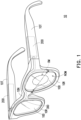
- FIG. 1 is a schematic view illustrating an electronic device according to an embodiment of the disclosure
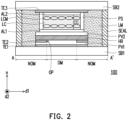
- FIG. 2 is a schematic cross-sectional view taken along a sectional line A-A' depicted in FIG. 1 .
- an electronic device 10 provided in this embodiment may be, for instance, configured for vision correction.
- the electronic device 10 may be configured to correct nearsightedness, farsightedness, presbyopia, astigmatism, or other visual impairment issues. That is, the electronic device 10 is, for instance, a kind of electronic glasses, which should however not be construed as a limitation in the disclosure.
- the electronic device 10 has a structure of two frames 10R, two temples 10T, and a bridge 10N, where the corresponding frames 10R are connected to the corresponding temples 10T, and the bridge 10N is connected to the two frames 10R.
- electronic elements in the electronic device 10 include an optical modulation structure 100, a circuit module 200, and a signal transmission element 300.
- the optical modulation structure 100 is, for instance, disposed on the frames 10R of the electronic device 10 and has, for instance, an electrically tunable focusing function.
- the optical modulation structure 100 has, for instance, an optical modulation region OM and a non-optical modulation region NOM, where the non-optical modulation region NOM may, for instance, surround the optical modulation region OM, which should however not be construed as a limitation in the disclosure.
- the non-optical modulation region NOM of the optical modulation structure 100 has a fixed focal length (or a fixed refractive power), and the optical modulation region OM of the optical modulation structure 100 may adjust its focal length (or refractive power) by changing voltages, for instance, which will be elaborated in the following embodiments.
- the circuit module 200 is disposed in the temples 10T of the electronic device 10 and is electrically connected to the optical modulation structure 100, for instance.
- the circuit module 200 may include a power supply unit (not shown), a touch sensor (not shown), a circuit board (not shown), and other corresponding elements to provide power to the optical modulation structure 100 and/or to drive the optical modulation structure 100, which should however not be construed as a limitation in the disclosure.
- the signal transmission element 300 may be disposed in the frames 10R, the temples 10T, and the bridge 10N of the electronic device 10 and may serve to electrically connect the circuit module 200 to the optical modulation structure 100, for instance.
- the optical modulation structure 100 includes a substrate SB1, a transparent electrode layer TE1, and a transparent electrode layer TE2.
- the substrate SB1 may be, for instance, a flexible substrate or an inflexible substrate.
- a material of the substrate SB 1 may include glass, plastic, or a combination thereof, for instance.
- the material of the substrate SB1 may include quartz, sapphire, polymethyl methacrylate (PMMA), polycarbonate (PC), polyimide (PI), polyethylene terephthalate (PET), any other appropriate material, or a combination of the above-mentioned materials; alternatively, the substrate SB1 may be a chip, which should however not be construed as a limitation in the disclosure.
- a thickness of the substrate SB1 is, for instance, 20 ⁇ m to 2,000,000 ⁇ m.
- the transparent electrode layer TE2 is, for instance, disposed on the transparent electrode layer TE1 and has an opening OP.
- the transparent electrode layer TE2 is, for instance, a patterned transparent electrode layer.
- the transparent electrode layer TE2 has a ring-shaped structure and has the opening OP, which should however not be construed as a limitation in the disclosure.
- a material of the transparent electrode layer TE2 may be identical or similar to the material of the transparent electrode layer TE1 and thus will not be repetitively described hereinafter.
- the high-resistivity film HR is, for instance, disposed on the insulation layer PV1. In this embodiment, the high-resistivity film HR is fully disposed on the transparent electrode layer TE2, which should however not be construed as a limitation in the disclosure.
- the high-resistivity film HR has a relatively high surface resistance, which is conducive to mitigating variations of an electric field in a direction (e.g., a first direction d1 or a second direction d2) perpendicular to the normal direction n of the optical modulation structure 100 when the optical modulation structure 100 is driven, so that the optical modulation structure 100 may provide a relatively good image quality.
- the transparent electrode layer TE3 is, for instance, disposed on the substrate SB2.
- a material of the transparent electrode layer TE3 may be identical or similar to the material of the transparent electrode layer TE1 and thus will not be further described hereinafter.
- the sealant SEAL is, for instance, disposed between the substrate SB1 and the substrate SB2 and may surround the medium layer LC, for instance.
- the sealant SEAL may be configured to bond the substrate SB1 and the substrate SB2, and the sealant SEAL may, together with the substrate SB1 or the substrate SB2, define a space for accommodating the medium layer LC.
- the liquid crystal molecules LCM may have a tilt angle in the optical modulation region OM, thereby changing the refractive index of the liquid crystal molecules LCM in the optical modulation region OM and further adjusting the focal length (or the refractive power) in the optical modulation region OM of the optical modulation structure 100.
- optical modulation structure 100a includes the components provided in the above embodiments and thus will not be further described hereinafter.
- the thickness of the substrate SB1 in the optical modulation region OM is less than the thickness of the substrate SB1 in the non-optical modulation region NOM.
- the substrate SB1 has a thickness T OM1 in the optical modulation region OM
- the substrate SB1 has a thickness T NOM1 in the non-optical modulation region NOM
- the thickness T OM1 of the substrate SB1 in the optical modulation region OM is less than the thickness T NOM1 of the substrate SB 1 in the non-optical modulation region NOM.
- a thickness T OM2 of the substrate SB2 in the optical modulation region OM is also less than a thickness T NOM2 of the substrate SB2 in the non-optical modulation region NOM, which will not be further described hereinafter.
- the sum of the thickness T OM2 of the substrate SB2 in the optical modulation region OM and a depth D GR2 of the groove GR2 in the substrate SB2 may be, for instance, equal to the thickness T NOM2 of the substrate SB2 in the non-optical modulation region NOM.
- the depth D GR2 of the groove GR2 in the substrate SB2 is less than or equal to 75% of the thickness T NOM2 of the substrate SB2 in the non-optical modulation region NOM (0 ⁇ D GR2 / T NOM2 ⁇ 75%), which should however not be construed as a limitation in the disclosure.
- a top surface of the corresponding first auxiliary support member PS 11 disposed on the substrate SB 1 may abut against a bottom surface of the corresponding first auxiliary support member PS 12 disposed on the substrate SB2, and there may be a cell gap between a top surface of the corresponding second auxiliary support member PS21 disposed on the substrate SB1 and a bottom surface of the corresponding second auxiliary support member PS22 disposed on the substrate SB2.
- the sidewall SB1S of the substrate SB1 may be, for instance, tilted with respect to the normal direction n of the optical modulation structure 100a, and the top surface SB1T of the substrate SB1 may be, for instance, perpendicular to the normal direction n of the optical modulation structure 100a, which should however not be constructed as a limitation in the disclosure.
- an included angle ⁇ between the sidewall SB1S of the substrate SB1 and the top surface SB1T of the substrate SB1 in the optical modulation region OM is greater than or equal to 30 degrees and less than 90 degrees, which should however not be constructed as a limitation in the disclosure.
- the groove GR2 of the substrate SB2 may be defined by the sidewall SB 12 and the top surface SB2T, which will not be further described hereinafter.
- FIG. 4 is a schematic cross-sectional view illustrating a portion of an electronic device according to a second embodiment of the disclosure. Note that the reference numbers and part of the content provided in the embodiment in FIG. 4 may be derived from those provided in the embodiment in FIG. 3 , the same or similar reference numbers serve to represent the same or similar elements, and the description of the same technical content is omitted.
- optical modulation structure 100b includes the components provided in the above embodiments and thus will not be further described hereinafter.
- optical modulation structure 100c includes the components provided in the above embodiments and thus will not be further described hereinafter.
- One of the differences between the optical modulation structure 100c in FIG. 5 and the optical modulation structure 100a lies in that: the first support member PS1 and the second support member PS2 in the optical modulation structure 100c are disposed on the substrate SB2.
- the top surface of the first support member PS1 disposed on the substrate SB2 may, for instance, abut against the alignment layer AL1 disposed on the substrate SB1, and there may be a cell gap between the top surface of the second support member PS2 disposed on the substrate SB2 and the alignment layer AL1 disposed on the substrate SB1, for instance.
- the height H PS1 of the first support member PS1 is greater than the height H PS2 of the second support member PS2, for instance.
- FIG. 6 is a schematic cross-sectional view illustrating a portion of an electronic device according to a fourth embodiment of the disclosure. Note that the reference numbers and part of the content provided in the embodiment in FIG. 6 may be derived from those provided in the embodiment in FIG. 5 , the same or similar reference numbers serve to represent the same or similar elements, and the description of the same technical content is omitted.
- optical modulation structure 100d includes the components provided in the above embodiments and thus will not be further described hereinafter.
- the substrate SB2 in the optical modulation structure 100d does not have the groove GR2, where the cell gap of the optical modulation region OM is defined by performing the etching process, the polishing process, the laser process, or a combination thereof on the substrate SB1 to form the groove GR1.
- the cell gap CG1 of the optical modulation region OM may be further expanded by forming the groove GR1 through performing the etching process on the substrate SB1.
- the thickness T OM2 of the substrate SB2 in the optical modulation region OM is equal to the thickness T NOM2 of the substrate SB2 in the non-optical modulation region NOM.
- the depth D GR1 of the groove GR1 of the substrate SB1 may be relatively large. Thereby, the overflow issue of the medium layer LC in the optical modulation structure 100d may be further mitigated.
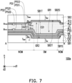
- FIG. 7 is a schematic cross-sectional view illustrating a portion of an electronic device according to a fifth embodiment of the disclosure. Note that the reference numbers and part of the content provided in the embodiment in FIG. 7 may be derived from those provided in the embodiment in FIG. 3 , the same or similar reference numbers serve to represent the same or similar elements, and the description of the same technical content is omitted.
- optical modulation structure 100e includes the components provided in the above embodiments and thus will not be further described hereinafter.
- One of the differences between the optical modulation structure 100e in FIG. 7 and the optical modulation structure 100a lies in that: the groove GR1 of the substrate SB1 and the groove GR2 of the substrate SB2 in the optical modulation structure 100e have different depths.
- the substrate SB1 in the optical modulation structure 100f has a step-shaped sidewall SB 1 S' in the non-optical modulation region NOM.
- multiple etching processes, polishing processes, laser processes, or a combination thereof may be performed to form a groove GR1' defined by the sidewall SB1S' and the top surface SB1T of the substrate SB1 on the substrate SB1, where the sidewall SB1S' of the substrate SB1 is step-shaped after multiple etching processes, polishing processes, laser processes, or a combination thereof is performed on the sidewall SB 1 S'.
- the substrate SB2 may also have a step-shaped sidewall. Namely, each of the substrate SB1 and the substrate SB2 may have the step-shaped sidewall at the same time, or one of the substrate SB1 and the substrate SB2 has the step-shaped sidewall, which should however not be construed as a limitation in the disclosure.
- FIG. 9 is a schematic cross-sectional view illustrating a portion of an electronic device according to a seventh embodiment of the disclosure. Note that the reference numbers and part of the content provided in the embodiment in FIG. 9 may be derived from those provided in the embodiment in FIG. 3 , the same or similar reference numbers serve to represent the same or similar elements, and the description of the same technical content is omitted.
- optical modulation structure 100g includes the components provided in the above embodiments and thus will not be further described hereinafter.
- One of the differences between the optical modulation structure 100g in FIG. 9 and the optical modulation structure 100a lies in that: the first support member PS1 and the second support member PS2 in the optical modulation structure 100g are disposed on the substrate SB1, and the optical modulation structure 100g further includes a third support member PS3.
- the top surface of the first support member PS1 disposed on the substrate SB1 may, for instance, abut against the alignment layer AL2 disposed on the substrate SB2, and there may be a cell gap between the top surface of the second support member PS2 disposed on the substrate SB1 and the alignment layer AL2 disposed on the substrate SB2, for instance.
- the third support member PS3 of the optical modulation structure 100g is disposed in the optical modulation region OM, and two opposite surfaces of the third support member PS3 may, for instance, abut against the alignment layer AL1 disposed on the substrate SB1 and abut against the alignment layer AL2 disposed on the substrate SB2.
- a height H PS3 of the third support member PS3 is greater than the height H PS1 of the first support member PS1, for instance.
- the shape of the third support member PS3 may be spherical, columnar, or any other appropriate shape, for instance. Although the shape of the third support member PS3 shown in FIG. 9 is spherical, this should however not be construed as a limitation in the disclosure.
- the optical modulation structure of the electronic device provided in one or more embodiments of the disclosure has a novel design; through forming at least one groove in the substrate of the optical modulation structure according to one or more embodiments of the disclosure, the cell gap of the optical modulation region is greater than the cell gap of the non-optical modulation region, and the liquid crystal cell gap in the optical modulation region may be increased, thereby increasing the range of the adjustable refractive power of the optical modulation structure provided in one or more embodiments of the disclosure.
Landscapes
- Physics & Mathematics (AREA)
- Nonlinear Science (AREA)
- General Physics & Mathematics (AREA)
- Optics & Photonics (AREA)
- Chemical & Material Sciences (AREA)
- Crystallography & Structural Chemistry (AREA)
- Health & Medical Sciences (AREA)
- Ophthalmology & Optometry (AREA)
- Mathematical Physics (AREA)
- General Health & Medical Sciences (AREA)
- Optical Modulation, Optical Deflection, Nonlinear Optics, Optical Demodulation, Optical Logic Elements (AREA)
- Mechanical Light Control Or Optical Switches (AREA)
Applications Claiming Priority (1)
| Application Number | Priority Date | Filing Date | Title |
|---|---|---|---|
| TW112100431A TWI886430B (zh) | 2023-01-05 | 2023-01-05 | 電子裝置 |
Publications (2)
| Publication Number | Publication Date |
|---|---|
| EP4398024A1 true EP4398024A1 (de) | 2024-07-10 |
| EP4398024B1 EP4398024B1 (de) | 2025-10-22 |
Family
ID=89190637
Family Applications (1)
| Application Number | Title | Priority Date | Filing Date |
|---|---|---|---|
| EP23215763.6A Active EP4398024B1 (de) | 2023-01-05 | 2023-12-12 | Elektronische vorrichtung |
Country Status (4)
| Country | Link |
|---|---|
| US (1) | US12339459B2 (de) |
| EP (1) | EP4398024B1 (de) |
| CN (1) | CN118295152A (de) |
| TW (1) | TWI886430B (de) |
Citations (4)
| Publication number | Priority date | Publication date | Assignee | Title |
|---|---|---|---|---|
| JP2006293241A (ja) * | 2005-04-14 | 2006-10-26 | Citizen Electronics Co Ltd | 液晶レンズ及びその製造方法 |
| US7688408B2 (en) * | 2005-09-21 | 2010-03-30 | Epson Imaging Devices Corporation | Liquid crystal device and electronic apparatus |
| EP2562593B1 (de) * | 2010-04-19 | 2016-10-05 | Citizen Holdings Co., Ltd. | Unberandete linse und herstellungsverfahren für eine berandete linse |
| CN111913319A (zh) * | 2020-09-14 | 2020-11-10 | 广东工业大学 | 一种圆环电极液晶透镜 |
Family Cites Families (8)
| Publication number | Priority date | Publication date | Assignee | Title |
|---|---|---|---|---|
| US20020027679A1 (en) * | 1999-11-23 | 2002-03-07 | Popovich Milan M. | Optical polarization method and apparatus |
| US7359023B2 (en) * | 2001-02-28 | 2008-04-15 | Compound Photonics U.S. Corporation | Display system with pixel electrodes separated from a common electrode by different optical distances |
| US7253872B2 (en) * | 2003-09-29 | 2007-08-07 | Sharp Kabushiki Kaisha | Liquid crystal display apparatus comprising wall portions formed in a plurality of openings or cut-out portions of an electrode |
| JP4337893B2 (ja) * | 2007-03-12 | 2009-09-30 | エプソンイメージングデバイス株式会社 | 液晶装置及び電子機器 |
| US8149377B2 (en) | 2008-06-22 | 2012-04-03 | Lensvector Inc. | Tunable-focusing liquid crystal lens cell and method of fabrication thereof |
| US8421990B2 (en) * | 2011-04-27 | 2013-04-16 | Silicon Touch Technology Inc. | Liquid crystal lens |
| JP6550967B2 (ja) * | 2015-06-30 | 2019-07-31 | セイコーエプソン株式会社 | 有機el装置、有機el装置の製造方法、及び電子機器 |
| JP7229789B2 (ja) * | 2019-01-22 | 2023-02-28 | 株式会社ジャパンディスプレイ | 表示装置、及び、表示装置を組み込んだ電子機器 |
-
2023
- 2023-01-05 TW TW112100431A patent/TWI886430B/zh active
- 2023-12-04 US US18/527,374 patent/US12339459B2/en active Active
- 2023-12-08 CN CN202311682899.5A patent/CN118295152A/zh active Pending
- 2023-12-12 EP EP23215763.6A patent/EP4398024B1/de active Active
Patent Citations (4)
| Publication number | Priority date | Publication date | Assignee | Title |
|---|---|---|---|---|
| JP2006293241A (ja) * | 2005-04-14 | 2006-10-26 | Citizen Electronics Co Ltd | 液晶レンズ及びその製造方法 |
| US7688408B2 (en) * | 2005-09-21 | 2010-03-30 | Epson Imaging Devices Corporation | Liquid crystal device and electronic apparatus |
| EP2562593B1 (de) * | 2010-04-19 | 2016-10-05 | Citizen Holdings Co., Ltd. | Unberandete linse und herstellungsverfahren für eine berandete linse |
| CN111913319A (zh) * | 2020-09-14 | 2020-11-10 | 广东工业大学 | 一种圆环电极液晶透镜 |
Also Published As
| Publication number | Publication date |
|---|---|
| TW202429165A (zh) | 2024-07-16 |
| CN118295152A (zh) | 2024-07-05 |
| EP4398024B1 (de) | 2025-10-22 |
| US20240231106A1 (en) | 2024-07-11 |
| US12339459B2 (en) | 2025-06-24 |
| TWI886430B (zh) | 2025-06-11 |
Similar Documents
| Publication | Publication Date | Title |
|---|---|---|
| KR101611906B1 (ko) | 터치 패널을 갖는 입체 영상 액정 표시 장치 및 이의 제조 방법 | |
| US9046710B2 (en) | Stereoscopic image conversion panel and stereoscopic image display apparatus having the same | |
| JP5699394B2 (ja) | 液晶シリンドリカルレンズアレイおよび表示装置 | |
| CN101681048B (zh) | 液晶显示装置 | |
| CN106226930B (zh) | 一种菲涅尔透镜装置 | |
| WO2018161650A1 (zh) | 显示面板和显示装置 | |
| CN102866556A (zh) | 一种液晶变焦透镜及其变焦控制方法 | |
| KR100765308B1 (ko) | 액정 표시 장치 | |
| CN107765480B (zh) | 显示装置 | |
| KR20150081106A (ko) | 표시 장치 | |
| CN107219573A (zh) | 菲涅尔透镜及眼镜 | |
| CN103376602A (zh) | 液晶光学元件和图像显示装置 | |
| EP4398024B1 (de) | Elektronische vorrichtung | |
| KR20060134538A (ko) | 기판 어셈블리 및 이를 갖는 표시 장치 | |
| US10824020B2 (en) | Polarization independent optical phase modulator | |
| EP3258310B1 (de) | Anzeigevorrichtung | |
| CN120335191A (zh) | 显示基板和显示装置 | |
| JP5114853B2 (ja) | 表示装置 | |
| US10613404B2 (en) | Liquid crystal optical element and optical apparatus | |
| TW202532931A (zh) | 電子裝置 | |
| US12332537B2 (en) | Electronic device | |
| TWI907781B (zh) | 電子裝置 | |
| CN102662282A (zh) | 一种蓝相液晶面板和显示装置 | |
| JP2009223301A (ja) | 液晶レンズ | |
| CN115236888A (zh) | 电子装置 |
Legal Events
| Date | Code | Title | Description |
|---|---|---|---|
| PUAI | Public reference made under article 153(3) epc to a published international application that has entered the european phase |
Free format text: ORIGINAL CODE: 0009012 |
|
| STAA | Information on the status of an ep patent application or granted ep patent |
Free format text: STATUS: THE APPLICATION HAS BEEN PUBLISHED |
|
| AK | Designated contracting states |
Kind code of ref document: A1 Designated state(s): AL AT BE BG CH CY CZ DE DK EE ES FI FR GB GR HR HU IE IS IT LI LT LU LV MC ME MK MT NL NO PL PT RO RS SE SI SK SM TR |
|
| STAA | Information on the status of an ep patent application or granted ep patent |
Free format text: STATUS: REQUEST FOR EXAMINATION WAS MADE |
|
| 17P | Request for examination filed |
Effective date: 20241227 |
|
| GRAP | Despatch of communication of intention to grant a patent |
Free format text: ORIGINAL CODE: EPIDOSNIGR1 |
|
| STAA | Information on the status of an ep patent application or granted ep patent |
Free format text: STATUS: GRANT OF PATENT IS INTENDED |
|
| INTG | Intention to grant announced |
Effective date: 20250611 |
|
| GRAS | Grant fee paid |
Free format text: ORIGINAL CODE: EPIDOSNIGR3 |
|
| GRAA | (expected) grant |
Free format text: ORIGINAL CODE: 0009210 |
|
| STAA | Information on the status of an ep patent application or granted ep patent |
Free format text: STATUS: THE PATENT HAS BEEN GRANTED |
|
| AK | Designated contracting states |
Kind code of ref document: B1 Designated state(s): AL AT BE BG CH CY CZ DE DK EE ES FI FR GB GR HR HU IE IS IT LI LT LU LV MC ME MK MT NL NO PL PT RO RS SE SI SK SM TR |
|
| REG | Reference to a national code |
Ref country code: CH Ref legal event code: F10 Free format text: ST27 STATUS EVENT CODE: U-0-0-F10-F00 (AS PROVIDED BY THE NATIONAL OFFICE) Effective date: 20251022 Ref country code: GB Ref legal event code: FG4D |
|
| REG | Reference to a national code |
Ref country code: DE Ref legal event code: R096 Ref document number: 602023007752 Country of ref document: DE |
|
| REG | Reference to a national code |
Ref country code: IE Ref legal event code: FG4D |
|
| PGFP | Annual fee paid to national office [announced via postgrant information from national office to epo] |
Ref country code: AT Payment date: 20260113 Year of fee payment: 3 |
|
| PGFP | Annual fee paid to national office [announced via postgrant information from national office to epo] |
Ref country code: FR Payment date: 20251226 Year of fee payment: 3 |