EP4397930B1 - Thermische holztrocknungsanlage durch co2-sequestration - Google Patents
Thermische holztrocknungsanlage durch co2-sequestration Download PDFInfo
- Publication number
- EP4397930B1 EP4397930B1 EP24150447.1A EP24150447A EP4397930B1 EP 4397930 B1 EP4397930 B1 EP 4397930B1 EP 24150447 A EP24150447 A EP 24150447A EP 4397930 B1 EP4397930 B1 EP 4397930B1
- Authority
- EP
- European Patent Office
- Prior art keywords
- drying
- drying chamber
- wood
- gas mixture
- temperature
- Prior art date
- Legal status (The legal status is an assumption and is not a legal conclusion. Google has not performed a legal analysis and makes no representation as to the accuracy of the status listed.)
- Active
Links
Images



Classifications
-
- F—MECHANICAL ENGINEERING; LIGHTING; HEATING; WEAPONS; BLASTING
- F26—DRYING
- F26B—DRYING SOLID MATERIALS OR OBJECTS BY REMOVING LIQUID THEREFROM
- F26B21/00—Arrangements for supplying or controlling air or other gases for drying solid materials or objects
- F26B21/40—Arrangements for supplying or controlling air or other gases for drying solid materials or objects using gases other than air
-
- F—MECHANICAL ENGINEERING; LIGHTING; HEATING; WEAPONS; BLASTING
- F26—DRYING
- F26B—DRYING SOLID MATERIALS OR OBJECTS BY REMOVING LIQUID THEREFROM
- F26B21/00—Arrangements for supplying or controlling air or other gases for drying solid materials or objects
- F26B21/001—Air generating units, e.g. movable or independent of drying enclosure
-
- F—MECHANICAL ENGINEERING; LIGHTING; HEATING; WEAPONS; BLASTING
- F26—DRYING
- F26B—DRYING SOLID MATERIALS OR OBJECTS BY REMOVING LIQUID THEREFROM
- F26B21/00—Arrangements for supplying or controlling air or other gases for drying solid materials or objects
- F26B21/20—Circulating air or gases in closed cycles, e.g. wholly within the drying enclosure
- F26B21/202—Circulating air or gases in closed cycles, e.g. wholly within the drying enclosure with means for changing the flow pattern, e.g. by reversing gas flow or by moving the materials or objects through subsequent compartments, at least two of which have a different flow direction
- F26B21/206—Circulating air or gases in closed cycles, e.g. wholly within the drying enclosure with means for changing the flow pattern, e.g. by reversing gas flow or by moving the materials or objects through subsequent compartments, at least two of which have a different flow direction by reversing fan rotation
-
- F—MECHANICAL ENGINEERING; LIGHTING; HEATING; WEAPONS; BLASTING
- F26—DRYING
- F26B—DRYING SOLID MATERIALS OR OBJECTS BY REMOVING LIQUID THEREFROM
- F26B21/00—Arrangements for supplying or controlling air or other gases for drying solid materials or objects
- F26B21/20—Circulating air or gases in closed cycles, e.g. wholly within the drying enclosure
- F26B21/202—Circulating air or gases in closed cycles, e.g. wholly within the drying enclosure with means for changing the flow pattern, e.g. by reversing gas flow or by moving the materials or objects through subsequent compartments, at least two of which have a different flow direction
- F26B21/208—Circulating air or gases in closed cycles, e.g. wholly within the drying enclosure with means for changing the flow pattern, e.g. by reversing gas flow or by moving the materials or objects through subsequent compartments, at least two of which have a different flow direction by air valves, movable baffles or nozzle arrangements
-
- F—MECHANICAL ENGINEERING; LIGHTING; HEATING; WEAPONS; BLASTING
- F26—DRYING
- F26B—DRYING SOLID MATERIALS OR OBJECTS BY REMOVING LIQUID THEREFROM
- F26B21/00—Arrangements for supplying or controlling air or other gases for drying solid materials or objects
- F26B21/20—Circulating air or gases in closed cycles, e.g. wholly within the drying enclosure
- F26B21/25—Circulating air or gases in closed cycles, e.g. wholly within the drying enclosure partly outside the drying enclosure
-
- F—MECHANICAL ENGINEERING; LIGHTING; HEATING; WEAPONS; BLASTING
- F26—DRYING
- F26B—DRYING SOLID MATERIALS OR OBJECTS BY REMOVING LIQUID THEREFROM
- F26B21/00—Arrangements for supplying or controlling air or other gases for drying solid materials or objects
- F26B21/30—Controlling, e.g. regulating, parameters of gas supply
- F26B21/33—Humidity
- F26B21/333—Humidity by condensing the moisture in the drying medium, which may be recycled, e.g. using a heat pump cycle
-
- F—MECHANICAL ENGINEERING; LIGHTING; HEATING; WEAPONS; BLASTING
- F26—DRYING
- F26B—DRYING SOLID MATERIALS OR OBJECTS BY REMOVING LIQUID THEREFROM
- F26B21/00—Arrangements for supplying or controlling air or other gases for drying solid materials or objects
- F26B21/30—Controlling, e.g. regulating, parameters of gas supply
- F26B21/35—Temperature; Pressure
-
- F—MECHANICAL ENGINEERING; LIGHTING; HEATING; WEAPONS; BLASTING
- F26—DRYING
- F26B—DRYING SOLID MATERIALS OR OBJECTS BY REMOVING LIQUID THEREFROM
- F26B21/00—Arrangements for supplying or controlling air or other gases for drying solid materials or objects
- F26B21/30—Controlling, e.g. regulating, parameters of gas supply
- F26B21/37—Velocity of flow; Quantity of flow
-
- F—MECHANICAL ENGINEERING; LIGHTING; HEATING; WEAPONS; BLASTING
- F26—DRYING
- F26B—DRYING SOLID MATERIALS OR OBJECTS BY REMOVING LIQUID THEREFROM
- F26B25/00—Details of general application not covered by group F26B21/00 or F26B23/00
- F26B25/22—Controlling the drying process in dependence on liquid content of solid materials or objects
-
- F—MECHANICAL ENGINEERING; LIGHTING; HEATING; WEAPONS; BLASTING
- F26—DRYING
- F26B—DRYING SOLID MATERIALS OR OBJECTS BY REMOVING LIQUID THEREFROM
- F26B3/00—Drying solid materials or objects by processes involving the application of heat
- F26B3/02—Drying solid materials or objects by processes involving the application of heat by convection, i.e. heat being conveyed from a heat source to the materials or objects to be dried by a gas or vapour, e.g. air
- F26B3/04—Drying solid materials or objects by processes involving the application of heat by convection, i.e. heat being conveyed from a heat source to the materials or objects to be dried by a gas or vapour, e.g. air the gas or vapour circulating over or surrounding the materials or objects to be dried
-
- F—MECHANICAL ENGINEERING; LIGHTING; HEATING; WEAPONS; BLASTING
- F26—DRYING
- F26B—DRYING SOLID MATERIALS OR OBJECTS BY REMOVING LIQUID THEREFROM
- F26B9/00—Machines or apparatus for drying solid materials or objects at rest or with only local agitation; Domestic airing cupboards
- F26B9/06—Machines or apparatus for drying solid materials or objects at rest or with only local agitation; Domestic airing cupboards in stationary drums or chambers
-
- F—MECHANICAL ENGINEERING; LIGHTING; HEATING; WEAPONS; BLASTING
- F26—DRYING
- F26B—DRYING SOLID MATERIALS OR OBJECTS BY REMOVING LIQUID THEREFROM
- F26B2210/00—Drying processes and machines for solid objects characterised by the specific requirements of the drying goods
- F26B2210/16—Wood, e.g. lumber, timber
Definitions
- the present invention relates to a thermal drying installation for wood by CO 2 sequestration, in particular, but not limited to, for the industrial drying of timber, industrial wood, energy wood, logs, and similar lignocellulosic material.
- timing, industrial timber means timber intended for use in secondary wood processing sectors, particularly for industry, construction, carpentry, or for exterior and interior urban, industrial, collective and domestic development.
- Wood is understood to mean any lignocellulosic material or similar compound capable of sequestering CO2 .
- CO2 sequestration here means any substitution, CO2 trapping, chemical reaction between CO2 /wood polymers/water or complexation, or stable accumulation of CO2 or carbonation of wood or water contained in wood with compounds such as wood to be dried or similar receiving material.
- a gas mixture is understood to mean the whole formed by the gaseous and liquid compounds circulating in the drying installation at a time t.
- the inlet duct comprises a solenoid valve configured to control the injection of the CO 2 gas mixture into the drying chamber, said inlet duct comprising at least two ducts connected to the drying chamber, each duct comprising at least one fan, each fan being configured to operate in a circulation direction, i.e. at least one fan towards the drying chamber and one fan from the drying chamber into the inlet duct, and in that the outlet duct comprises at least two ducts connected to the drying chamber, each duct comprising at least one fan being configured to operate in a circulation direction, i.e. at least one fan towards the drying chamber and one fan from the drying chamber towards the heating means.
- the CO2 recycling means are of the heat exchanger type comprising at least one cold battery, configured to gradually extract the water from the gas mixture, each cold battery being capable of extracting a chosen percentage of the water from said gas mixture.
- the heat exchanger of the CO2 recycling means is only active during the drying phase, and when the measured hygrometry of the circulating gas mixture is between a maximum threshold value and a minimum threshold value.
- the CO2 supply means belong to the group formed by a CO2 injection system from CO2 in a pressurized bottle, CO2 supply from the evacuation of a methanization installation, CO2 supply of the industrial chimney type, and ancillary CO2 sequestration wood drying installation, or a combination of them.
- the drying installation according to the invention also makes it possible to obtain a shrinkage of less than 5% of the wood, whereas the standard shrinkage with conventional drying means is 10 to 15%.
- the Applicant also observed that the drying installation according to the invention makes it possible to obtain dried wood with moisture uptake. lower, a reduction in the coloring of the dried wood, as well as the limitation/absence of the appearance of cracks during drying.
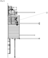
- the drying installation comprises at least one drying module C1, each drying module C1 having several functional groups including a heating chamber 1 comprising at least one drying tube into which the wood to be dried is introduced, heating means 2, CO2 supply means 3 , gas circulation means 4 allowing the renewal of the atmosphere inside the drying chamber 1, several metrology measurement units forming metrological means 5, and finally a computer control system 6 equipped with an API application programming interface.
- the drying module C1 has a drying chamber 1 composed of one or more hollow cylindrical drying tubes allowing the introduction of the wood to be dried.
- the drying chamber 1 is connected to the heating means 2 by an inlet duct 206a, and has an outlet duct 206b configured to evacuate a CO2 or CO2 / H2O gas mixture from said drying chamber 1 depending on the progress of the drying.
- the inlet duct 206a is arranged at a first end of the drying chamber 1 and the outlet duct 206b at a second end of the drying chamber 1 so as to allow longitudinal circulation of the CO2 gas mixture relative to the wood to be dried.
- the drying chamber 1 comprises a closed, heat-insulated tube with internal atmospheric recirculation.
- the drying chamber 1 comprises a minimum volume of 10m3 saturable in CO2 .
- the drying chamber 1 comprises metrological means 5 configured to measure parameters belonging to the group formed by hygrometry of the wood to be dried, hygrometry in drying chamber 1, temperature of the wood to be dried, temperature in drying chamber 1, pressure in drying chamber 1.
- the drying chamber 1 comprises at least one probe for measuring the temperature and humidity in the drying chamber 53.
- the drying chamber 1 comprises two probes for measuring the temperature and humidity in the drying chamber 53
- the drying chamber 1 comprises at least one probe for measuring the hygrometry of the wood to be dried 54.
- the drying chamber 1 comprises two probes for measuring the hygrometry of the wood to be dried 54.
- the drying chamber 1 further comprises a regulation box 61 configured to receive and process the data recorded by the hygrometry measuring probes of the wood to be dried 54.
- the drying chamber 1 further comprises a pressure measuring probe 55 in said drying chamber 1, allowing the emergency evacuation of part of the atmosphere contained in the drying chamber 1 in the event of critical pressure therein.
- each metrological measurement includes a set value or a group of set values to be respected, specific to each species or application of the wood to be dried.
- the critical pressure can be 1.5 bar.
- the drying chamber 1 further comprises door closing sensors 62, configured to detect the closing status of the doors for inserting the wood to be dried.
- drying chamber 1 is 5.5m long with a circulation diameter of 2.4 metres, cylindrical or quasi-cylindrical in shape and contained in a maritime container insulated with 60mm thick wood wool panels. This box is connected from one end to the other by a insulated ductwork, a 2-stage heating system and four centrifugal circulation fans capable of handling temperatures up to 250°C.
- the drying module C1 comprises CO 2 3 supply means configured to control the injection of the CO 2 gas mixture from at least one CO 2 source.
- the CO2 supply means 3 comprise a conduit connected on the one hand to the CO2 source, and on the other hand to the heating means 2, said conduit being equipped with a solenoid valve 701 allowing the control of the injection of CO2 into the drying module C1.
- the CO2 supply means 3 consist of at least one CO2 injection system from CO2 coming from the distribution system D1 to the heating means 2.
- the heating means 2 are of the immersion heater type and more particularly of the “in-line electric heater” type.
- the immersion heater has a power of 90 kW, and comprises an inlet through which the gases to be heated enter, an open cylindrical or quasi-cylindrical steel conduit, into which an immersion heater is inserted, and finally a second outlet opening for the gases thus heated.
- the immersion heater also comprises a thermostat for regulating the temperature of the immersion heater.
- the drying means 1 consist of a plurality of drying modules C1, connected to heating means 2 common to several drying modules C1.
- the drying means 1 consist of a plurality of drying modules C1, each connected to individual heating means 2.
- the inlet conduit 206a comprises a solenoid valve 702 configured to control the injection of the CO2 gas mixture into the drying chamber 1, as well as gas circulation means 4.
- the gas circulation means 4 of the inlet duct 206a comprise at least one fan 41 capable of operating bilaterally in two directions of circulation of the gas mixture, either towards the drying chamber 1, and from the drying chamber 1.
- the heating means 2 are also connected to an outlet duct 206b connecting an outlet end of the drying chamber 1 to said heating means 2, and forming a closed-loop circulation duct of the CO2 gas mixture.
- the gas circulation means 4 of the outlet duct 206b comprise at least one fan 42 capable of operating bilaterally in two directions of circulation of the gas mixture, either towards the drying chamber 1, and from the drying chamber 1.
- the outlet duct 206b comprises at least two ducts connected to the drying chamber 1, each duct comprising at least one fan 42. These fans 42 are configured to each operate in one direction of circulation, i.e. at least one fan towards the drying chamber 1 and one fan from the drying chamber towards the heating means 2.
- the circulation means 4 of the fan type 41, 42 are of the medium pressure, single-intake centrifugal fan type with a duct and turbine made of sheet steel, said fan comprising a turbine with forward-inclined blades made of galvanized sheet steel, the fan 51 being capable of withstanding a maximum temperature of the air or CO 2 to be transported of -20°C to 250°C.
- the alternating circulation of the CO 2 in the inlet duct 206a and outlet duct 206b in two circulation directions makes it possible to circulate the CO 2 longitudinally in the direction of the length of the drying chamber 1 with an injection and an extraction advantageously positioned at the ends of the drying chamber 1 and thus maintain a uniformity of the temperature of the gas mixture in the drying chamber 1 and thus allow drying of the wood and uniform treatment of the CO 2 in the wood.
- the invention also makes it possible to greatly limit the deformation of the square-edged timber and, more particularly, prevents the knots in the wood from deforming during drying. This reduced deformation of the wood during drying could represent a material saving of up to 20% depending on the applications.
- the fans 41, 42 of the inlet duct 206a and the outlet duct 206b are coupled to frequency variators which advantageously make it possible to reduce the rotation speed depending on the species of wood to be dried, and therefore the flow rate of the circulating gas mixture as a function of the humidity level of the wood and the temperature of the circulating gas mixture and thus optimize the uniformity of drying.
- the outlet conduit 206b further comprises a bypass for sampling the circulating gas mixture 45 and integrating CO 2 /CH 4 measuring means 56, configured to measure the proportion of CO 2 relative to the total volume of gas in circulation and the proportion of CH 4 circulating during the drying phase of the drying module C1 in CO 2 , and thus verify the CO 2 saturation in the entire circuit of the drying module C1.
- monitoring the CO 2 /CH 4 of the gas mixture during drying makes it possible to record the evolution of the concentration of the different compounds in the circulating gas mixture and thus allow the operation of the drying module 1 to be adjusted, but also to ensure the safety of the drying module C1 in the event of a drastic increase in the quantity of CH 4 .
- the outlet conduit 206b further comprises metrological means 5 configured to measure parameters belonging to the group formed by flow rate of the injected circulating CO2 gas mixture, temperature of the injected circulating CO2 gas mixture, and hygrometry of the circulating gas mixture.
- the outlet conduit 206b comprises at least one probe for measuring the temperature and the circulating flow rate 51 arranged upstream and one probe for measuring the temperature and the circulating flow rate 51 arranged downstream of the CO 2 recycling means 600.
- the outlet duct 206b comprises at least one temperature and humidity measuring probe 53 arranged upstream and one temperature and humidity measuring probe 53 arranged downstream of CO2 recycling means 600, and at least one temperature and circulating flow rate measuring probe 51 arranged upstream and one temperature and circulating flow rate measuring probe 51 arranged downstream of CO2 recycling means 600.
- such an arrangement makes it possible to monitor the composition of the circulating gas mixture, but also the activity of the CO2 recycling means 600 as well as their modulation.
- the drying module C1 further comprises CO2 recycling means 600 arranged at the outlet duct 206b allowing the separation of the water vapor and the gaseous CO2 present in the atmosphere extracted from the chamber 1 during drying, in order to be able to eliminate the water while recovering the CO2 in order to be stored, or to be directly reused in the installation.
- condensation recycling means 600 are used, reducing the temperature of the binary water vapor/ CO2 gas mixture extracted from the drying chamber 1 to a chosen temperature, allowing the condensation of the water in the gas mixture, which is then recovered by gravity in liquid form and eliminated.
- the recycling means 600 allow the drying of the internal atmosphere extracted from the drying chamber 1 via thermal condensation of the water vapor by cooling, on at least one heat exchanger equipped with at least one cold battery, it will be possible to advantageously place several cold batteries configured in series to increase the dehumidification capacity of each drying module C1. The system therefore allows the reinjection of the dehydrated atmosphere into the drying chamber 1.
- each heat exchanger includes at least one EV evaporator and at least one CO condenser.
- the heat exchanger of the CO2 recycling means 600 is only active during the drying phase, and when the measured hygrometry of the circulating gas mixture is between a maximum threshold value and a minimum threshold value.
- the humidity threshold values in drying chamber 1 are 20% for the minimum threshold and 100% for the maximum threshold.
- the recycling means 600 comprise a heat exchanger type system comprising at least two cold batteries, configured in series to gradually extract the water from the gas mixture, each cold battery being capable of extracting a chosen percentage of the water from said gas mixture.
- a series of cold batteries makes it possible to limit the humidity in the drying chamber 1, and thus make it possible to limit the duration of the drying cycle, making it possible to resolve the performance problem of a conventional heat exchanger when the humidity is higher than the critical operating value, and thus to reduce the duration of each cycle, causing the operation of each drying module C1 over a shorter period and limiting the associated energy expenditure.
- the water flow meter 57 is configured to record the discharge flow rate of the water to be removed, and thus makes it possible to correlate the quantity of water removed with the difference between the initial and final humidity level of the wood for a drying cycle.
- the heat exchanger of the recycling means 600 also allows the dehydrated gas mixture to be heated before reinjection into said installation.
- the heat exchanger is configured to reheat the cooled gas mixture after extraction of the water up to a temperature differential of 50°C with the temperature of the circulating gas mixture, for reinjection into the drying chamber 1.
- the drying chamber 1 comprises at least one evacuation circuit, which is followed by a so-called “breathing” conduit comprising at least one breathing solenoid valve 704, 705 of the drying chamber 1, which allows the injection of air coming from outside the installation into the drying chamber 1 and the evacuation of the gas mixture contained in said drying chamber 1.
- the drying module C1 also integrates a computer control system 6 comprising an application programming interface API.
- the application programming interface allows, on the one hand, the management of the sending of instructions to each of the components of the installation, and on the other hand to integrate the data received by the various metrological means 5, in order to adjust the instructions sent to the components of the installation.
- the computer control system 6 also allows the monitoring, measurement and recording of all measured metrological values in a table (including energy consumption), as well as emergency procedures (stop without resuming drying or with resuming drying).
- control computer system 6 is equipped with an application programming interface API capable of implementing a drying process.
- the computer control system 6 opens the solenoid valve 701 of the CO 2 supply means 3 so as to inject new CO 2.
- the drying module C1 further comprises at least one ambient sensor arranged outside of said module, and capable of recording the temperature and humidity in the environment surrounding said drying module.
- the computer control system 6 is further configured to enable the control of the dehumidification of the CO 2 via the activation of the recycling means 600 as a function of a minimum (20%) and maximum (100%) value of the hygrometry of the atmosphere of the drying chamber 1. This phase is continuous regardless of the initial hygrometry of the wood.
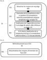
- the thermal drying installation for wood by CO 2 sequestration thus described with reference to figures 1 And 2 implements a process of drying and sequestration of CO2 in the wood comprising a series of stages.
- metrological data and parameters of the wood to be dried are acquired by measuring metrological means 5.
- the measurement of the various parametric data is carried out to calibrate the setpoint values to be applied.
- the wood to be dried is inserted into drying chamber 1, and then the drying chamber is hermetically sealed.
- the difference between the surface and core temperature of the wood must be less than or equal to 20°C throughout the drying operation.
- the maximum quantity of CO2 sequestered is 250kg/ m3 of wood.
- the CO2 supply means 3 are activated.
- the CO 2 saturation step S2 includes a sub-step S21 of verification of the CO 2 saturation in the circulating gas mixture, to ensure that said minimum CO 2 saturation for starting a drying cycle is reached.
- the verification of CO 2 saturation S21 is implemented by measurement via the CO 2 /CH 4 measuring means 56 at the level of the evacuation duct of the drying module C1.
- the verification of the CO2 saturation S21 is implemented by measuring the percentage of CO2 in the circulating gas mixture.
Landscapes
- Engineering & Computer Science (AREA)
- Mechanical Engineering (AREA)
- General Engineering & Computer Science (AREA)
- Life Sciences & Earth Sciences (AREA)
- Microbiology (AREA)
- Drying Of Solid Materials (AREA)
- Chemical And Physical Treatments For Wood And The Like (AREA)
Claims (9)
- Thermische Trocknungsanlage für Holz durch CO2-Sequestrierung, ausgestattet mit mindestens einem Trocknungsmodul unter CO2-Atmosphäre (C1), welches umfasst:- Eine Trocknungskammer (1) mit mindestens einem hohlen, zylindrischen oder quasi-zylindrischen Trocknungsrohr mit geeignetem Durchmesser und Länge für die gewählte Holzdimensionen.- CO2-Zufuhrsystem (3) zum Einspritzen von gasförmigem CO2 in die Trocknungskammer.- Heizeinrichtungen (2) zur Erwärmung des zirkulierenden CO2.- Gaszirkulationssystem (4) zur erzwungenen Zirkulation des CO2 von einem Ende der Trocknungskammer (1) zum anderen in einem geschlossenen Kreislauf entlang der Länge der Kammer mit Einspritzungs- und Extraktionspunkten an den Enden sowie zur Erneuerung der Atmosphäre innerhalb der Kammer (1).- Recyclingsystem (600) zur Trennung von Wasserdampf und gasförmigem CO2 aus der extrahierten Atmosphäre (1) während des Trocknungsprozesses.- Messtechnik (5) zur Erfassung physikalischer Veränderungen des Trocknungsmoduls während der Erwärmung.- Computergesteuertes System (6) zur Steuerung der CO2-Zufuhr (3), der Gaszirkulation (4), der Heizeinrichtungen (2) und des Recyclings (600) anhand von programmierten Vorgaben, Sollwerten und Trocknungszeiten gemäß der gewünschten Holzqualität. Zudem ermöglicht es Messungen, Vergleiche und Anpassungen der Betriebsparameter bei Abweichungen. Das Trocknungsmodul (Cl) ist dadurch gekennzeichnet, dass die gasförmigen Zirkulationsmittel (4) ein Flussumkehr-Modul umfassen, das konfiguriert ist, um die CO2-Zirkulation in zwei Richtungen zu ermöglichen: Erste Zirkulationsrichtung: CO2 strömt durch die Trocknungskammer (1) zwischen einem Einlasskanal (206a), der die Heizeinrichtungen (2) mit der Kammer verbindet und die Einspritzung des CO2-Gasgemischs steuert, sowie einem Auslasskanal (206b), der das Austreten des Gasgemischs aus der Kammer reguliert und wieder den Heizeinrichtungen (2) zuführt. Dadurch entsteht ein geschlossenes Zirkulationssystem für das CO2-Gasgemisch. Zweite Zirkulationsrichtung (entgegengesetzt zur ersten): CO2 wird längs durch die gesamte Trocknungskammer (1) geführt, mit Einspritz- und Extraktionspunkten an beiden Enden der Kammer. Diese Zirkulationsweise ist darauf ausgelegt, eine gleichmäßige Wärmeverteilung in der Kammer zu gewährleisten.
- Trocknungsanlage gemäß Anspruch 1, dadurch gekennzeichnet, dass der Einlasskanal (206a) ein Magnetventil (702) umfasst, das zur Steuerung der Einspritzung des gasförmigen CO2-Gemischs in die Trocknungskammer (1) konfiguriert ist. Ebenso umfasst das Gaszirkulationssystem (4) mindestens einen Ventilator (41), der in beide Richtungen arbeiten kann, sowohl in Richtung der Trocknungskammer (1) als auch aus der Trocknungskammer (1) heraus. Der Auslasskanal (206b) enthält ebenfalls ein Magnetventil (706) zur Steuerung der Abfuhr des gasförmigen CO2-Gemischs aus der Trocknungskammer (1). Das Gaszirkulationssystem (4) umfasst außerdem mindestens einen Ventilator (42), der ebenfalls in beide Richtungen arbeiten kann, sowohl in Richtung der Trocknungskammer (1) als auch aus der Trocknungskammer (1) heraus. Die Gaszirkulationsmittel (4) sind so konfiguriert, dass sie simultan in derselben Flussrichtung arbeiten können.
- Trocknungsanlage gemäß Anspruch 1, dadurch gekennzeichnet, dass der Einlasskanal (206a) ein Magnetventil (702) umfasst, das konfiguriert ist, um die Einspritzung des Gasgemischs CO2 in die Trocknungskammer (1) zu steuern. Der Einlasskanal (206a) umfasst mindestens zwei Leitungen, die mit der Trocknungskammer (1) verbunden sind. Jede Leitung enthält mindestens einen Ventilator (41, 44), wobei jeder Ventilator (41, 44) so konfiguriert ist, dass er in einer bestimmten Strömungsrichtung arbeitet. Mindestens ein Ventilator (41) führt das Gasgemisch in die Trocknungskammer (1), während ein Ventilator (41) das Gasgemisch aus der Trocknungskammer (1) in den Einlasskanal (206a) leitet. Der Auslasskanal (206b) umfasst mindestens zwei Leitungen, die mit der Trocknungskammer (1) verbunden sind. Jede Leitung enthält mindestens einen Ventilator (42, 43), die so konfiguriert sind, dass sie in einer bestimmten Strömungsrichtung arbeiten. Mindestens ein Ventilator (42, 43) führt das Gasgemisch in die Trocknungskammer (1), während ein Ventilator (42) das Gasgemisch aus der Trocknungskammer (1) zu den Heizeinrichtungen (2) leitet.
- Trocknungsanlage gemäß einem der Ansprüche 1 bis 3, dadurch gekennzeichnet, dass der Auslasskanal (206b) außerdem messtechnische Mittel (5) umfasst, die konfiguriert sind, um Parameter aus der folgenden Gruppe zu messen: Durchflussrate des zirkulierenden und eingespritzten CO2-Gasgemischs, Temperatur des zirkulierenden und eingespritzten CO2-Gasgemischs, Feuchtigkeitsgehalt (Hygrometrie) des zirkulierenden Gasgemischs.
- Trocknungsanlage gemäß einem der Ansprüche 1 bis 4, dadurch gekennzeichnet, dass die Recyclingsysteme (600) für CO2 ein Wärmetauscher-System umfassen, das so konfiguriert ist, dass es: Das zirkulierende Gasgemisch abkühlt, um die Kondensation des darin enthaltenen Wassers zu ermöglichen und die kondensierte Flüssigkeit zu extrahieren. Das gekühlte Gasgemisch nach der Wasserextraktion wieder erwärmt, wobei eine Temperaturdifferenz von 50 °C zwischen der Ausgangstemperatur des zirkulierenden Gasgemischs und der erneuten Einspritzung in die Trocknungskammer (1) hergestellt wird.
- Trocknungsanlage gemäß Anspruch 5, dadurch gekennzeichnet, dass die Recyclingsysteme (600) für CO2 einen Wärmetauscher umfassen, der mindestens eine Kühlbatterie enthält. Diese Kühlbatterie ist so konfiguriert, dass sie das Wasser schrittweise aus dem Gasgemisch extrahiert. Jede Kühlbatterie ist in der Lage, einen festgelegten Prozentsatz des enthaltenen Wassers aus dem Gasgemisch zu entfernen.
- Trocknungsanlage gemäß einem der Ansprüche 5 oder 6, dadurch gekennzeichnet, dass der Wärmetauscher des Recyclingsystems (600) für CO2 ausschließlich während der Trocknungsphase aktiv ist. Die Aktivierung des Wärmetauschers erfolgt nur, wenn die gemessene Feuchtigkeit des zirkulierenden Gasgemischs innerhalb eines festgelegten maximalen und minimalen Schwellenwerts liegt.
- Trocknungsanlage gemäß einem der Ansprüche 1 bis 7, dadurch gekennzeichnet, dass die CO2-Zufuhrsysteme (3) zu einer der folgenden Gruppen gehören: Einspritzsystem für CO2 aus Druckgasflaschen, CO2-Zufuhr aus der Abgasführung einer Biogasanlage, CO2-Zufuhr aus Industrieabgasen (Schornsteinanlagen), CO2-Zufuhr aus angegliederter Holztrocknungsanlage mit CO2-Sequestrierung, oder eine Kombination dieser Systeme.
- Trocknungsanlage gemäß einem der Ansprüche 1 bis 8, dadurch gekennzeichnet, dass das computergesteuerte Steuerungssystem (6) mit einer Anwendungsprogrammierschnittstelle (API) ausgestattet ist, die konfiguriert ist für::- Erfassung messtechnischer Daten und Parameter des zu trocknenden Holzes durch Messung messtechnischer Mittel (5) •- Aktivierung der CO2-Zufuhrsysteme (3), um die Trocknungskammer (1) mit CO2 zu sättigen •- Überprüfung, ob die CO2-Sättigung im zirkulierenden Gasgemisch ausreichend ist, um einen Trocknungszyklus zu starten, durch Kontrolle mittels der Messeinrichtung CO2/CH4 (56) im Abflusskanal .- Aktivierung der Heizeinrichtungen (2), um die Holzfeuchtigkeit durch Erwärmung zu regulieren, sobald die gemessene CO2-Sättigung ausreichend ist.- Falls die gemessene Holzfeuchtigkeit über 30 % liegt: Erwärmung mit einer Temperaturbegrenzung gemäß einer ersten Solltemperatur T1, mit einem gewählten Temperaturgradienten G1, um das freie Wasser aus dem Holz zu extrahieren und die Zirkulationsmittel (4) zu aktivieren. (4);- Falls die gemessene Holzfeuchtigkeit unter 30 % liegt: Erwärmung mit einer Temperaturbegrenzung gemäß einer zweiten Solltemperatur T2, mit einem gewählten Temperaturgradienten G2, um das gebundene Wasser aus dem Holz zu extrahieren und die Zirkulationsmittel (4) zu aktivieren.Unterteilung in folgende Schritte::- Stabilisierung der Temperatur des zirkulierenden CO2 in der Trocknungskammer (1) in einer ersten Phase, wenn eine gemessene Feuchtigkeit von ≤30 % erreicht wird. Aktivierung der Recyclingsysteme (600), dann schrittweise Erhöhung der CO2-Temperatur in der Kammer in einer zweiten Phase, bis eine gewählte Zwischenzielwert-Feuchtigkeit Hi des Holzes erreicht wird. Die Heizeinrichtungen (2) werden so aktiviert, dass die Erwärmung mit einer maximalen Temperatur erfolgt, die durch eine zweite Solltemperatur T2 von 120 °C mit einem gewählten Temperaturgradienten G2 definiert ist - abhängig vom spezifischen Trocknungsprofil des Holzes, um das gebundene Wasser zu extrahieren.- Deaktivierung der Recyclingsysteme (600) und Modulation der Heizeinrichtungen (2), um die Temperatur der Heizkammer (1) in einer ersten Phase zu senken, bis eine dritte Solltemperatur T3 zur Stabilisierung erreicht wird, gemäß einem gewählten Temperaturgradienten G3. Diese Absenkung erfolgt, wenn die durch die Messeinrichtung zur Bestimmung der Holzfeuchtigkeit (54) erfasste durchschnittliche Holzfeuchtigkeit den gewählten Zwischenzielwert Hi erreicht - es sei denn, eine der gemessenen Feuchtigkeitswerte liegt über Hi + A%, wobei A ein gewählter Wert ist. In diesem Fall wird die Solltemperatur T3 für eine festgelegte Zeit aufrechterhalten, bis die über Hi + A% liegende Feuchtigkeitswerte stabil sind und innerhalb eines Bereichs unterhalb von Hi + A% bleiben.;- Deaktivierung der Heizeinrichtungen (2), um die Temperatur der Trocknungskammer (1) in einer zweiten Phase weiter zu senken, sobald die endgültige Zielwert-Feuchtigkeit HC des Holzes erreicht ist.
Priority Applications (1)
| Application Number | Priority Date | Filing Date | Title |
|---|---|---|---|
| HRP20251228TT HRP20251228T1 (hr) | 2023-01-05 | 2024-01-04 | Instalacija za toplinsko sušenje drva sekvestracijom co2 |
Applications Claiming Priority (2)
| Application Number | Priority Date | Filing Date | Title |
|---|---|---|---|
| FR2300136A FR3144861B1 (fr) | 2023-01-05 | 2023-01-05 | Procédé de séchage thermique de bois sous atmosphère CO2 |
| FR2300130A FR3144860B1 (fr) | 2023-01-05 | 2023-01-05 | installation de séchage thermique de bois par séquestration CO2 |
Publications (3)
| Publication Number | Publication Date |
|---|---|
| EP4397930A1 EP4397930A1 (de) | 2024-07-10 |
| EP4397930B1 true EP4397930B1 (de) | 2025-07-09 |
| EP4397930C0 EP4397930C0 (de) | 2025-07-09 |
Family
ID=88020799
Family Applications (3)
| Application Number | Title | Priority Date | Filing Date |
|---|---|---|---|
| EP23768836.1A Pending EP4623259A1 (de) | 2023-01-05 | 2023-09-11 | Anlage zur verarbeitung von co2 aus einer co2-gasquelle mit hoher ausgangsleistung und mittel zum trocknen von holz in einer co2-atmosphäre |
| EP24150447.1A Active EP4397930B1 (de) | 2023-01-05 | 2024-01-04 | Thermische holztrocknungsanlage durch co2-sequestration |
| EP24150450.5A Active EP4397931B1 (de) | 2023-01-05 | 2024-01-04 | Verfahren zur thermischen trocknung von holz unter co2-atmosphäre |
Family Applications Before (1)
| Application Number | Title | Priority Date | Filing Date |
|---|---|---|---|
| EP23768836.1A Pending EP4623259A1 (de) | 2023-01-05 | 2023-09-11 | Anlage zur verarbeitung von co2 aus einer co2-gasquelle mit hoher ausgangsleistung und mittel zum trocknen von holz in einer co2-atmosphäre |
Family Applications After (1)
| Application Number | Title | Priority Date | Filing Date |
|---|---|---|---|
| EP24150450.5A Active EP4397931B1 (de) | 2023-01-05 | 2024-01-04 | Verfahren zur thermischen trocknung von holz unter co2-atmosphäre |
Country Status (9)
| Country | Link |
|---|---|
| US (3) | US20260104202A1 (de) |
| EP (3) | EP4623259A1 (de) |
| CN (1) | CN120530296A (de) |
| CA (2) | CA3225457A1 (de) |
| ES (2) | ES3044038T3 (de) |
| HR (2) | HRP20251514T1 (de) |
| HU (1) | HUE073069T2 (de) |
| PL (2) | PL4397931T3 (de) |
| WO (3) | WO2024146703A1 (de) |
Family Cites Families (8)
| Publication number | Priority date | Publication date | Assignee | Title |
|---|---|---|---|---|
| GB849613A (en) | 1958-07-11 | 1960-09-28 | Gordon Albert Gray | An improved machine for drying copra |
| CA2732034C (fr) * | 2011-02-14 | 2013-04-30 | Yves Lacoursiere | System de sechage de bois sur rails a ventilation en ligne |
| CA2809873A1 (fr) * | 2013-03-25 | 2013-05-29 | Yves Lacoursiere | Systeme pour secher des morceaux de bois |
| CN107178966B (zh) * | 2017-07-03 | 2019-11-29 | 阜南县铭钰柳木工艺品有限公司 | 半成品柳编篮中期烘干方法 |
| CN109163547A (zh) * | 2018-08-24 | 2019-01-08 | 湖州市南浔三亚家私有限公司 | 杨树木单板的干燥方法 |
| FR3090835B1 (fr) * | 2018-12-19 | 2023-01-13 | Ways | [Procédé de séchage thermique de bois sous atmosphère CO2, installation de séchage pour la mise en œuvre dudit procédé et produit obtenu] |
| CN110715541B (zh) * | 2019-10-14 | 2024-05-28 | 南京航空航天大学 | 基于超临界二氧化碳储能的高温农产品干燥设备及方法 |
| CN114034167A (zh) * | 2021-11-30 | 2022-02-11 | 罗洋 | 一种超临界二氧化碳干燥装置 |
-
2023
- 2023-09-11 US US19/145,609 patent/US20260104202A1/en active Pending
- 2023-09-11 EP EP23768836.1A patent/EP4623259A1/de active Pending
- 2023-09-11 WO PCT/EP2023/074864 patent/WO2024146703A1/fr not_active Ceased
- 2023-09-11 CN CN202380090520.3A patent/CN120530296A/zh active Pending
-
2024
- 2024-01-04 ES ES24150447T patent/ES3044038T3/es active Active
- 2024-01-04 EP EP24150447.1A patent/EP4397930B1/de active Active
- 2024-01-04 CA CA3225457A patent/CA3225457A1/fr active Pending
- 2024-01-04 PL PL24150450.5T patent/PL4397931T3/pl unknown
- 2024-01-04 WO PCT/EP2024/050163 patent/WO2024146925A1/fr not_active Ceased
- 2024-01-04 HU HUE24150447A patent/HUE073069T2/hu unknown
- 2024-01-04 HR HRP20251514TT patent/HRP20251514T1/hr unknown
- 2024-01-04 HR HRP20251228TT patent/HRP20251228T1/hr unknown
- 2024-01-04 US US18/404,698 patent/US20240240863A1/en active Pending
- 2024-01-04 CA CA3225462A patent/CA3225462A1/fr active Pending
- 2024-01-04 PL PL24150447.1T patent/PL4397930T3/pl unknown
- 2024-01-04 EP EP24150450.5A patent/EP4397931B1/de active Active
- 2024-01-04 US US18/404,732 patent/US20240230229A1/en active Pending
- 2024-01-04 ES ES24150450T patent/ES3055837T3/es active Active
- 2024-01-04 WO PCT/EP2024/050171 patent/WO2024146929A1/fr not_active Ceased
Also Published As
| Publication number | Publication date |
|---|---|
| PL4397930T3 (pl) | 2025-11-24 |
| HRP20251514T1 (hr) | 2026-01-02 |
| ES3044038T3 (en) | 2025-11-26 |
| EP4397931A1 (de) | 2024-07-10 |
| US20240240863A1 (en) | 2024-07-18 |
| US20260104202A1 (en) | 2026-04-16 |
| CA3225462A1 (fr) | 2024-07-05 |
| EP4397931C0 (de) | 2025-09-10 |
| US20240230229A1 (en) | 2024-07-11 |
| EP4397931B1 (de) | 2025-09-10 |
| EP4397930C0 (de) | 2025-07-09 |
| EP4623259A1 (de) | 2025-10-01 |
| CN120530296A (zh) | 2025-08-22 |
| EP4397930A1 (de) | 2024-07-10 |
| WO2024146703A1 (fr) | 2024-07-11 |
| PL4397931T3 (pl) | 2026-02-02 |
| ES3055837T3 (en) | 2026-02-16 |
| HRP20251228T1 (hr) | 2025-12-05 |
| WO2024146925A1 (fr) | 2024-07-11 |
| CA3225457A1 (fr) | 2024-07-05 |
| HUE073069T2 (hu) | 2025-12-28 |
| WO2024146929A1 (fr) | 2024-07-11 |
Similar Documents
| Publication | Publication Date | Title |
|---|---|---|
| EP3899392B1 (de) | Verfahren zur thermischen trocknung von holz in einer co2-atmosphäre, trocknungsanlage zur durchführung des verfahrens und erhaltenes produkt | |
| JPWO2009041632A1 (ja) | 水蒸気透過度を測定するための装置とその方法 | |
| US5852880A (en) | Method of drying lumber | |
| JPWO2011132391A1 (ja) | 透湿度測定装置及び透湿度測定方法 | |
| EP4182156B1 (de) | Verfahren zum belüften eines ofens | |
| EP4397930B1 (de) | Thermische holztrocknungsanlage durch co2-sequestration | |
| RU2255276C2 (ru) | Способ сушки древесины | |
| EP1558884A1 (de) | Verfahren zur behandlung einer ladung von gestapelten elementen aus holzartigem material, insbesondere einer holzladung, durch eine hoch-temperatur wärmebehandlung | |
| DK2710099T3 (en) | Method for monitoring and control of a torreficeringstemperatur | |
| CA3122225C (fr) | Procede de sechage thermique du bois sous atmosphere de co2, installation de sechage pour la mise en oeuvre dudit procede et produit obtenu | |
| FR3144860A1 (fr) | installation de séchage thermique de bois par séquestration CO2 | |
| FR2914734A1 (fr) | Procede pour le sechage de bois et dispositif pour sa mise en oeuvre | |
| WO2025185837A1 (fr) | Systeme et procede de production de biochar par séchage et pyrolyse lente d'un materiau lignocellulosique sous atmosphere co2 | |
| FR3144861A1 (fr) | Procédé de séchage thermique de bois sous atmosphère CO2 | |
| JP2007144866A (ja) | 木材の調湿乾燥方法及びその装置 | |
| FR2636127A1 (fr) | Procede et installation de sechage de bois, du type discontinu en presence de vapeur d'eau | |
| SU1008590A1 (ru) | Способ сушки пиломатериалов в камере периодического действи | |
| FR3062799A1 (fr) | Dispositif pour la production et le traitement de flux gazeux a travers un volume de liquide regule automatiquement | |
| RU78911U1 (ru) | Установка для сушки древесины | |
| EP4688207A1 (de) | Kopplung eines sekundären kühlmittels und wärmeübertragungseffektes in einem verfahren und einer vorrichtung zur behandlung von rauchgasen | |
| BE629487A (de) | ||
| FR3016770A1 (fr) | Procede de traitement du jus de raisin et dispositif pour sa mise en œuvre |
Legal Events
| Date | Code | Title | Description |
|---|---|---|---|
| REG | Reference to a national code |
Ref country code: HR Ref legal event code: TUEP Ref document number: P20251228T Country of ref document: HR |
|
| PUAI | Public reference made under article 153(3) epc to a published international application that has entered the european phase |
Free format text: ORIGINAL CODE: 0009012 |
|
| STAA | Information on the status of an ep patent application or granted ep patent |
Free format text: STATUS: THE APPLICATION HAS BEEN PUBLISHED |
|
| AK | Designated contracting states |
Kind code of ref document: A1 Designated state(s): AL AT BE BG CH CY CZ DE DK EE ES FI FR GB GR HR HU IE IS IT LI LT LU LV MC ME MK MT NL NO PL PT RO RS SE SI SK SM TR |
|
| STAA | Information on the status of an ep patent application or granted ep patent |
Free format text: STATUS: REQUEST FOR EXAMINATION WAS MADE |
|
| 17P | Request for examination filed |
Effective date: 20250119 |
|
| GRAP | Despatch of communication of intention to grant a patent |
Free format text: ORIGINAL CODE: EPIDOSNIGR1 |
|
| STAA | Information on the status of an ep patent application or granted ep patent |
Free format text: STATUS: GRANT OF PATENT IS INTENDED |
|
| RIC1 | Information provided on ipc code assigned before grant |
Ipc: F26B 25/22 20060101ALI20250210BHEP Ipc: F26B 21/10 20060101ALI20250210BHEP Ipc: F26B 21/06 20060101ALI20250210BHEP Ipc: F26B 21/02 20060101ALI20250210BHEP Ipc: F26B 3/04 20060101ALI20250210BHEP Ipc: F26B 21/14 20060101ALI20250210BHEP Ipc: F26B 9/06 20060101AFI20250210BHEP |
|
| INTG | Intention to grant announced |
Effective date: 20250305 |
|
| GRAS | Grant fee paid |
Free format text: ORIGINAL CODE: EPIDOSNIGR3 |
|
| GRAA | (expected) grant |
Free format text: ORIGINAL CODE: 0009210 |
|
| STAA | Information on the status of an ep patent application or granted ep patent |
Free format text: STATUS: THE PATENT HAS BEEN GRANTED |
|
| AK | Designated contracting states |
Kind code of ref document: B1 Designated state(s): AL AT BE BG CH CY CZ DE DK EE ES FI FR GB GR HR HU IE IS IT LI LT LU LV MC ME MK MT NL NO PL PT RO RS SE SI SK SM TR |
|
| REG | Reference to a national code |
Ref country code: GB Ref legal event code: FG4D Free format text: NOT ENGLISH |
|
| REG | Reference to a national code |
Ref country code: CH Ref legal event code: EP |
|
| REG | Reference to a national code |
Ref country code: IE Ref legal event code: FG4D Free format text: LANGUAGE OF EP DOCUMENT: FRENCH |
|
| REG | Reference to a national code |
Ref country code: DE Ref legal event code: R096 Ref document number: 602024000276 Country of ref document: DE |
|
| U01 | Request for unitary effect filed |
Effective date: 20250806 |
|
| U07 | Unitary effect registered |
Designated state(s): AT BE BG DE DK EE FI FR IT LT LU LV MT NL PT RO SE SI Effective date: 20250819 |
|
| REG | Reference to a national code |
Ref country code: CH Ref legal event code: R17 Free format text: ST27 STATUS EVENT CODE: U-0-0-R10-R17 (AS PROVIDED BY THE NATIONAL OFFICE) Effective date: 20251001 |
|
| REG | Reference to a national code |
Ref country code: ES Ref legal event code: FG2A Ref document number: 3044038 Country of ref document: ES Kind code of ref document: T3 Effective date: 20251126 Ref country code: SK Ref legal event code: T3 Ref document number: E 47280 Country of ref document: SK |
|
| REG | Reference to a national code |
Ref country code: HR Ref legal event code: T1PR Ref document number: P20251228 Country of ref document: HR |
|
| REG | Reference to a national code |
Ref country code: GR Ref legal event code: EP Ref document number: 20250402012 Country of ref document: GR Effective date: 20251112 |
|
| REG | Reference to a national code |
Ref country code: HU Ref legal event code: AG4A Ref document number: E073069 Country of ref document: HU |
|
| PG25 | Lapsed in a contracting state [announced via postgrant information from national office to epo] |
Ref country code: IS Free format text: LAPSE BECAUSE OF FAILURE TO SUBMIT A TRANSLATION OF THE DESCRIPTION OR TO PAY THE FEE WITHIN THE PRESCRIBED TIME-LIMIT Effective date: 20251109 |
|
| PG25 | Lapsed in a contracting state [announced via postgrant information from national office to epo] |
Ref country code: NO Free format text: LAPSE BECAUSE OF FAILURE TO SUBMIT A TRANSLATION OF THE DESCRIPTION OR TO PAY THE FEE WITHIN THE PRESCRIBED TIME-LIMIT Effective date: 20251009 |
|
| PGFP | Annual fee paid to national office [announced via postgrant information from national office to epo] |
Ref country code: GR Payment date: 20251219 Year of fee payment: 3 |
|
| PGFP | Annual fee paid to national office [announced via postgrant information from national office to epo] |
Ref country code: IE Payment date: 20251223 Year of fee payment: 3 |
|
| PGFP | Annual fee paid to national office [announced via postgrant information from national office to epo] |
Ref country code: PL Payment date: 20251222 Year of fee payment: 3 |
|
| PGFP | Annual fee paid to national office [announced via postgrant information from national office to epo] |
Ref country code: SK Payment date: 20251223 Year of fee payment: 3 |
|
| PG25 | Lapsed in a contracting state [announced via postgrant information from national office to epo] |
Ref country code: RS Free format text: LAPSE BECAUSE OF FAILURE TO SUBMIT A TRANSLATION OF THE DESCRIPTION OR TO PAY THE FEE WITHIN THE PRESCRIBED TIME-LIMIT Effective date: 20251009 |
|
| REG | Reference to a national code |
Ref country code: HR Ref legal event code: ODRP Ref document number: P20251228 Country of ref document: HR Payment date: 20251230 Year of fee payment: 3 |
|
| U20 | Renewal fee for the european patent with unitary effect paid |
Year of fee payment: 3 Effective date: 20251231 |
|
| PGFP | Annual fee paid to national office [announced via postgrant information from national office to epo] |
Ref country code: HU Payment date: 20251223 Year of fee payment: 3 |
|
| PG25 | Lapsed in a contracting state [announced via postgrant information from national office to epo] |
Ref country code: SM Free format text: LAPSE BECAUSE OF FAILURE TO SUBMIT A TRANSLATION OF THE DESCRIPTION OR TO PAY THE FEE WITHIN THE PRESCRIBED TIME-LIMIT Effective date: 20250709 |
|
| PGFP | Annual fee paid to national office [announced via postgrant information from national office to epo] |
Ref country code: ES Payment date: 20260209 Year of fee payment: 3 |
|
| PGFP | Annual fee paid to national office [announced via postgrant information from national office to epo] |
Ref country code: HR Payment date: 20260121 Year of fee payment: 3 |
|
| PGFP | Annual fee paid to national office [announced via postgrant information from national office to epo] |
Ref country code: TR Payment date: 20260102 Year of fee payment: 3 |
|
| PGFP | Annual fee paid to national office [announced via postgrant information from national office to epo] |
Ref country code: CZ Payment date: 20260102 Year of fee payment: 3 |