EP4397828A1 - Anti-panic lock with escape door opener - Google Patents
Anti-panic lock with escape door opener Download PDFInfo
- Publication number
- EP4397828A1 EP4397828A1 EP23214500.3A EP23214500A EP4397828A1 EP 4397828 A1 EP4397828 A1 EP 4397828A1 EP 23214500 A EP23214500 A EP 23214500A EP 4397828 A1 EP4397828 A1 EP 4397828A1
- Authority
- EP
- European Patent Office
- Prior art keywords
- lock
- electronic module
- blocking
- blocking element
- latch
- Prior art date
- Legal status (The legal status is an assumption and is not a legal conclusion. Google has not performed a legal analysis and makes no representation as to the accuracy of the status listed.)
- Pending
Links
Images


Classifications
-
- E—FIXED CONSTRUCTIONS
- E05—LOCKS; KEYS; WINDOW OR DOOR FITTINGS; SAFES
- E05B—LOCKS; ACCESSORIES THEREFOR; HANDCUFFS
- E05B9/00—Lock casings or latch-mechanism casings ; Fastening locks or fasteners or parts thereof to the wing
- E05B9/02—Casings of latch-bolt or deadbolt locks
-
- E—FIXED CONSTRUCTIONS
- E05—LOCKS; KEYS; WINDOW OR DOOR FITTINGS; SAFES
- E05B—LOCKS; ACCESSORIES THEREFOR; HANDCUFFS
- E05B47/00—Operating or controlling locks or other fastening devices by electric or magnetic means
- E05B47/06—Controlling mechanically-operated bolts by electro-magnetically-operated detents
- E05B47/0603—Controlling mechanically-operated bolts by electro-magnetically-operated detents the detent moving rectilinearly
-
- E—FIXED CONSTRUCTIONS
- E05—LOCKS; KEYS; WINDOW OR DOOR FITTINGS; SAFES
- E05B—LOCKS; ACCESSORIES THEREFOR; HANDCUFFS
- E05B63/00—Locks or fastenings with special structural characteristics
- E05B63/0056—Locks with adjustable or exchangeable lock parts
-
- E—FIXED CONSTRUCTIONS
- E05—LOCKS; KEYS; WINDOW OR DOOR FITTINGS; SAFES
- E05B—LOCKS; ACCESSORIES THEREFOR; HANDCUFFS
- E05B65/00—Locks or fastenings for special use
- E05B65/10—Locks or fastenings for special use for panic or emergency doors
- E05B65/108—Electronically controlled emergency exits
-
- E—FIXED CONSTRUCTIONS
- E05—LOCKS; KEYS; WINDOW OR DOOR FITTINGS; SAFES
- E05B—LOCKS; ACCESSORIES THEREFOR; HANDCUFFS
- E05B47/00—Operating or controlling locks or other fastening devices by electric or magnetic means
- E05B2047/0091—Retrofittable electric locks, e.g. an electric module can be attached to an existing manual lock
Definitions
- the invention relates to a mechanical lock with an additional electronic module according to the features of the preamble of claim 1 and a method for locking and unlocking a mechanical lock with an additional electronic module according to the features of the preamble of claim 14.
- a lock is known that can be adapted to specific circumstances. It is intended that individual extensions can be connected to the lock housing, which can include, for example, additional locking elements or drive devices and thus extend the lock housing. This makes it possible to individually upgrade the lock and adapt it to increased security requirements.
- the lock housing holder in the door must be designed to accommodate the enlarged lock housing.
- a motor lock with a drive module is known, which controls the entire lock mechanism via a slide plate for locking or unlocking.
- Electronic additional modules are also known, which can be arranged outside the lock housing, whereby the additional module parts of the Locking mechanism in a lock is moved by an electronic drive of the additional module. This movement drives the locking mechanism and thus locks or unlocks the lock.
- the disadvantage of such additional modules is that the electronic drive usually affects the entire locking mechanism.
- door openers are also used which are arranged in the frame of the door and work together with a mechanical lock to open or close electrically remote-controlled doors.
- An important criterion for such electrical door openers is the volume of the door opener and the holding force that can be achieved with the door opener.
- the disadvantage here is that a corresponding holder must be formed in the frame for the door opener.
- the object of the present invention is to provide a mechanical lock with an additional electronic module which covers a wide range of applications and can be manufactured in a simple manner.
- a further object of the present invention is to eliminate the need for a separate door opener and replace it with a lock.
- a method for locking and unlocking a mechanical lock for a pivotably mounted leaf of a door or window with an additional electronic module comprising locking or unlocking a lock latch by displacing a blocking element through a lock mechanism of the lock, wherein the blocking element can be displaced by the lock mechanism into a blocking position in which the blocking element engages behind the lock latch and a movement of the lock latch is blocked, and wherein the blocking element can be displaced by the lock mechanism into a release position in which the lock latch is pivotable and translationally displaceable.
- the advantage of the device and method according to the invention is that the additional electronic module acts directly on blocking or releasing the lock latch and thus a purely mechanical opening of the door by the lock mechanism alone can be prevented via an electronic control.
- a further advantage is that the additional electronic module does not act on the entire lock mechanism.
- a further advantage of the device according to the invention and the method according to the invention is that the functionality of the purely mechanical lock is expanded by the additional electronic module, whereby additional components such as a door opener can be replaced by the lock according to the invention with the additional electronic module and the method according to the invention. This means that it is no longer necessary to form an opening in the frame for the door opener.
- Another advantage is that by replacing the lock with the additional electronic module as a door opener, a much higher holding force is achieved compared to known door openers, since the latch interacts with a latch holder of a frame and not with moving parts of a door opener.
- the electronic module blocking element can be displaced by a drive of the electronic module into a blocking position in which the electronic module blocking element engages behind the lock latch and a movement of the lock latch is blocked, and wherein the electronic module blocking element can be displaced by the drive of the electronic module into a release position in which the lock latch can be pivoted and translationally displaced.
- the lock has a locking element that can be actuated by the lock mechanism, and the locking element can be actuated by a slide plate of the lock mechanism between a pre-locked locking position and an unlocking position retracted into the lock housing.
- the lock mechanism comprises a central slide plate, which serves to control the locking element and the blocking element.
- the locking of the locking element can be carried out via a guide rail arranged in the slide plate, which interacts with a pin of the locking element.
- the handle may be designed as a door handle or push bar.
- the electronic additional module can be controlled by a door control unit or a door terminal that is spatially assigned to the door with the lock.
- the electronic additional module can also be controlled, i.e. additionally or alone, by a remote control unit.
- the remote control unit can be connected to the lock or the electronic additional module by cable or bus.
Landscapes
- Business, Economics & Management (AREA)
- Emergency Management (AREA)
- Engineering & Computer Science (AREA)
- Structural Engineering (AREA)
- Mechanical Engineering (AREA)
- Casings For Electric Apparatus (AREA)
Abstract
Vorgeschlagen wird ein Schloss (1) mit einem elektronischen Zusatzmodul (2), wobei das Schloss (1) ein Schlossgehäuse (10) und eine darin angeordnete Schlossmechanik mit einer sperrbaren Schlossfalle (11) aufweiset und das Schloss (1) ein von der Schlossmechanik bewegbaren Blockierelement (12) aufweist, und wobei das Blockierelement (12) durch die Schlossmechanik in eine Blockierstellung verlagerbar ist, und wobei das Blockierelement (12) durch die Schlossmechanik in eine Freigabestellung verlagerbar ist, in der die Schlossfalle (11) verschwenkbar und translational verschiebbar ist, und wobei das elektronische Zusatzmodul (2) im Schlossgehäuse (10) angeordnet ist. Wesentlich dabei ist, dass das elektronische Zusatzmodul (2) eine reine mechanische Öffnung der Tür (3) verhindert, indem das elektronische Zusatzmodul (2) ein schaltbares Verlagerungselement (25) aufweist, welches eine Verlagerung des Blockierelements (12) durch die Schlossmechanik verhindert oder erlaubt, und/oder dass das elektronische Zusatzmodul (2) ein verlagerbares Elektronikmodul-Blockierelement (20) aufweist, welches eine Verlagerung der Schlossfalle (11) verhindert oder erlaubt.

Description
Die Erfindung betrifft ein mechanisches Schloss mit einem elektronischen Zusatzmodul nach den Merkmalen des Oberbegriffs des Anspruchs 1 und ein Verfahren zur Verriegelung und Entriegelung eines mechanischen Schlosses mit einem elektronischen Zusatzmodul nach den Merkmalen des Oberbegriffs des Anspruchs 14.The invention relates to a mechanical lock with an additional electronic module according to the features of the preamble of
Aus der
Bekannt sind auch elektronische Zusatzmodule, welche außerhalb des Schlossgehäuses angeordnet werden können, wobei das Zusatzmodul Teile der Schlossmechanik in einem Schloss durch einen elektronischen Antrieb des Zusatzmoduls bewegt. Durch diese Bewegung wird die Schlossmechanik angetrieben und das Schloss dadurch verriegelt oder entriegelt. Der Nachteil derartiger Zusatzmodule besteht darin, dass durch den elektronischen Antrieb meist auf die gesamte Schlossmechanik eingewirkt wird.Electronic additional modules are also known, which can be arranged outside the lock housing, whereby the additional module parts of the Locking mechanism in a lock is moved by an electronic drive of the additional module. This movement drives the locking mechanism and thus locks or unlocks the lock. The disadvantage of such additional modules is that the electronic drive usually affects the entire locking mechanism.
Weiter werden in der Praxis Türöffner verwendet, welche im Rahmen der Tür angeordnet sind und mit einem mechanischen Schloss zusammenwirken, um elektrisch fernschaltbare Türen für den Durchgang freizugeben oder zu blockieren. Ein wesentliches Kriterium für solche elektrischen Türöffner ist dabei zum einen das Bauvolumen des Türöffners und zum anderen die mit dem Türöffner zu realisierende Haltekraft. Nachteilig ist hier, dass für den Türöffner eine entsprechende Aufnahme im Rahmen ausgebildet werden muss.In practice, door openers are also used which are arranged in the frame of the door and work together with a mechanical lock to open or close electrically remote-controlled doors. An important criterion for such electrical door openers is the volume of the door opener and the holding force that can be achieved with the door opener. The disadvantage here is that a corresponding holder must be formed in the frame for the door opener.
Der vorliegenden Erfindung liegt die Aufgabe zugrunde, ein mechanisches Schloss mit einem elektronischen Zusatzmodul bereitzustellen, welches einen großen Anwendungsbereich umfasst und dabei auf einfache Art und Weise herstellbar ist. Eine weitere Aufgabe der vorliegenden Erfindung ist es, die Notwendigkeit eines separaten Türöffners zu eliminieren und durch ein Schloss zu ersetzen.The object of the present invention is to provide a mechanical lock with an additional electronic module which covers a wide range of applications and can be manufactured in a simple manner. A further object of the present invention is to eliminate the need for a separate door opener and replace it with a lock.
Die Aufgabe wird erfindungsgemäß durch ein mechanisches Schloss mit einem elektronischen Zusatzmodul nach den Merkmalen des Anspruchs 1 gelöst.The object is achieved according to the invention by a mechanical lock with an additional electronic module according to the features of
Erfindungsgemäß wird ein mechanisches Schloss für einen schwenkbar gelagerten Flügel einer Tür oder eines Fensters mit einem elektronischen Zusatzmodul zur Verfügung gestellt,
- wobei das Schloss ein Schlossgehäuse und eine darin angeordnete Schlossmechanik mit einer sperrbaren Schlossfalle aufweist und das Schloss ein von der Schlossmechanik bewegbaren Blockierelement aufweist, und
- wobei das Blockierelement durch die Schlossmechanik in eine Blockierstellung verlagerbar ist, in der das Blockierelement die Schlossfalle hintergreift und eine Bewegung der Schlossfalle blockiert ist, und wobei das Blockierelement durch die Schlossmechanik in eine Freigabestellung verlagerbar ist, in der die Schlossfalle verschwenkbar und translational verschiebbar ist, und
- wobei das elektronische Zusatzmodul im Schlossgehäuse angeordnet ist. Wesentlich dabei ist, dass das elektronische Zusatzmodul eine reine mechanische Öffnung der Tür verhindert, indem
- das elektronische Zusatzmodul ein schaltbares Verlagerungselement aufweist, welches eine Verlagerung des Blockierelements durch die Schlossmechanik verhindert oder erlaubt, und/oder
- dass das elektronische Zusatzmodul ein verlagerbares Elektronikmodul-Blockierelement aufweist, welches eine Verlagerung der Schlossfalle verhindert oder erlaubt.
- wherein the lock has a lock housing and a lock mechanism arranged therein with a lockable lock latch and the lock has a blocking element movable by the lock mechanism, and
- wherein the blocking element can be displaced by the lock mechanism into a blocking position in which the blocking element engages behind the lock latch and a movement of the lock latch is blocked, and wherein the blocking element can be displaced by the lock mechanism into a release position in which the lock latch can be pivoted and translationally displaced, and
- The electronic additional module is located in the lock housing. It is important that the electronic additional module prevents a purely mechanical opening of the door by
- the additional electronic module has a switchable displacement element which prevents or allows displacement of the blocking element by the lock mechanism, and/or
- that the additional electronic module has a movable electronic module blocking element which prevents or allows the lock latch to be moved.
Weiter wird die Aufgabe durch ein Verfahren zur Verriegelung und Entriegelung eines mechanischen Schlosses mit einem elektronischen Zusatzmodul nach den Merkmalen des Anspruchs 14 gelöst.Furthermore, the object is achieved by a method for locking and unlocking a mechanical lock with an additional electronic module according to the features of
Erfindungsgemäß wird ein Verfahren zur Verriegelung und Entriegelung eines mechanischen Schlosses für einen schwenkbar gelagerten Flügel einer Tür oder eines Fensters mit einem elektronischen Zusatzmodul vorgeschlagen umfassend, Verriegelung oder Entriegelung einer Schlossfalle durch eine Verlagerung eines Blockierelements durch eine Schlossmechanik des Schlosses,
wobei das Blockierelement durch die Schlossmechanik in eine Blockierstellung verlagerbar ist, in der das Blockierelement die Schlossfalle hintergreift und eine Bewegung der Schlossfalle blockiert ist, und wobei das Blockierelement durch die Schlossmechanik in eine Freigabestellung verlagerbar ist, in der die Schlossfalle verschwenkbar und translational verschiebbar ist.According to the invention, a method for locking and unlocking a mechanical lock for a pivotably mounted leaf of a door or window with an additional electronic module is proposed, comprising locking or unlocking a lock latch by displacing a blocking element through a lock mechanism of the lock,
wherein the blocking element can be displaced by the lock mechanism into a blocking position in which the blocking element engages behind the lock latch and a movement of the lock latch is blocked, and wherein the blocking element can be displaced by the lock mechanism into a release position in which the lock latch is pivotable and translationally displaceable.
Wesentlich dabei ist, dass das elektronische Zusatzmodul eine reine mechanische Öffnung der Tür durch die Schlossmechanik verhindert,
- indem das elektronische Zusatzmodul durch ein schaltbares Verlagerungselement eine Übertragung der Bewegung der Schlossmechanik auf das Blockierelement verhindert oder erlaubt, und/oder
- indem das elektronische Zusatzmodul durch ein verlagerbares Elektronikmodul-Blockierelement die Verlagerung der Schlossfalle verhindert oder erlaubt.
- by the additional electronic module preventing or allowing the movement of the lock mechanism to be transferred to the blocking element by means of a switchable displacement element, and/or
- The additional electronic module prevents or allows the lock latch to be moved using a movable electronic module blocking element.
Der Vorteil der erfindungsgemäßen Vorrichtung und des erfindungsgemäßen Verfahrens liegt darin, dass das elektronische Zusatzmodul direkt auf eine Blockierung oder Freigabe der Schlossfalle einwirkt und dadurch eine rein mechanische Öffnung der Tür alleine durch die Schlossmechanik über eine elektronische Steuerung verhindert werden kann. Ein weiterer Vorteil liegt auch darin, dass durch das elektronische Zusatzmodul nicht auf die gesamte Schlossmechanik eingewirkt wird.The advantage of the device and method according to the invention is that the additional electronic module acts directly on blocking or releasing the lock latch and thus a purely mechanical opening of the door by the lock mechanism alone can be prevented via an electronic control. A further advantage is that the additional electronic module does not act on the entire lock mechanism.
Ein weiterer Vorteil der erfindungsgemäßen Vorrichtung und des erfindungsgemäßen Verfahrens liegt darin, dass die Funktionalität des rein mechanischen Schlosses durch das elektronische Zusatzmodul erweitert wird, wodurch zusätzliche Bauteile, wie beispielsweise ein Türöffner durch das erfindungsgemäße Schloss mit dem elektronischen Zusatzmodul und das erfindungsgemäße Verfahren ersetzt werden können. Dadurch ist es nicht mehr notwendig, eine Öffnung im Rahmen für den Türöffner auszubilden. Vorteilhaft ist auch, dass durch den Ersatz des Schlosses mit dem elektronischen Zusatzmodul als Türöffner eine viel höhere Haltekraft gegenüber bekannten Türöffnern erhalten wird, da die Falle mit einer Fallenaufnahme eines Rahmens und nicht mit beweglichen Teilen eines Türöffners zusammenwirkt.A further advantage of the device according to the invention and the method according to the invention is that the functionality of the purely mechanical lock is expanded by the additional electronic module, whereby additional components such as a door opener can be replaced by the lock according to the invention with the additional electronic module and the method according to the invention. This means that it is no longer necessary to form an opening in the frame for the door opener. Another advantage is that by replacing the lock with the additional electronic module as a door opener, a much higher holding force is achieved compared to known door openers, since the latch interacts with a latch holder of a frame and not with moving parts of a door opener.
Ein weiterer Vorteil liegt darin, dass das Schloss ohne das Zusatzmodul als vollwertiges rein mechanisches Schloss betrieben werden kann. Eine Aufrüstung des Schlosses kann zu einem beliebigen Zeitpunkt erfolgen, also bereits bei der Herstellung des Schlosses, oder bei der Montage des Schlosses oder zu einem späteren Zeitpunkt, d. h. nach einer Montage und Inbetriebnahme des Schlosses.Another advantage is that the lock can be operated as a fully functional, purely mechanical lock without the additional module. The lock can be upgraded at any time, i.e. during manufacture of the lock, during assembly of the lock or at a later time, i.e. after assembly and commissioning of the lock.
Für den Vertrieb kann auch ein Fertigungsbausatz umfassend das Schloss und das elektronische Zusatzmodul vorgesehen sein. Alternativ kann das elektronische Zusatzmodul auch separat zu dem Schloss vertrieben werden, um nachträglich ein bereits installiertes Schloss um ein entsprechendes elektronisches Zusatzmodul aufzurüsten.A production kit comprising the lock and the additional electronic module can also be provided for sale. Alternatively, the additional electronic module can also be sold separately from the lock in order to subsequently upgrade an already installed lock with a corresponding additional electronic module.
Durch die elektronische Blockierung oder Freigabe der Schlossfalle durch das elektronische Zusatzmodul ist es möglich, das erfindungsgemäße Schloss mit dem elektronischen Zusatzmodul und das erfindungsgemäße Verfahren in Fluchttüren und zur Fluchttürsicherung einzusetzen.By electronically blocking or releasing the lock latch using the additional electronic module, it is possible to use the lock according to the invention with the additional electronic module and the method according to the invention in escape doors and for escape door security.
In einer Verriegelung der Tür befindet sich die Schlossfalle in ihrer vorgeschlossenen Stellung, wobei das Blockierelement die Schlossfalle dabei in einer Blockierstellung hintergreift, sodass die Schlossfalle fixiert ist und nicht in den Schlossgehäuse eingeschoben werden kann. In einer Entriegelung der Tür befindet sich das Blockierelement in einer Freigabestellung, sodass die Schlossfalle in den Schlossgehäuse eingeschoben werden kann.When the door is locked, the lock latch is in its pre-locked position, with the blocking element engaging behind the lock latch in a blocking position so that the lock latch is fixed and cannot be pushed into the lock housing. When the door is unlocked, the blocking element is in a release position so that the lock latch can be pushed into the lock housing.
Es kann vorgesehen sein, dass das elektronische Zusatzmodul als Antrieb einen Motor, vorzugweise einen Elektromotor oder eine Spule aufweist. Es kann vorgesehen sein, dass das elektronische Zusatzmodul ein Getriebe zur Übertragung einer Bewegung des Antriebs auf das schaltbare Verlagerungselement oder das Elektronikmodul-Blockierelement aufweist.It can be provided that the additional electronic module has a motor as a drive, preferably an electric motor or a coil. It can be provided that the additional electronic module has a gear for transmitting a movement of the drive to the switchable displacement element or the electronic module blocking element.
Es kann vorgesehen sein, dass das Elektronikmodul-Blockierelement durch einen Antrieb des Elektronikmoduls in eine Blockierstellung verlagerbar ist, in der das Elektronikmodul-Blockierelement die Schlossfalle hintergreift und eine Bewegung der Schlossfalle blockiert ist, und wobei das Elektronikmodul-Blockierelement durch den Antrieb des Elektronikmoduls in eine Freigabestellung verlagerbar ist, in der die Schlossfalle verschwenkbar und translational verschiebbar ist.It can be provided that the electronic module blocking element can be displaced by a drive of the electronic module into a blocking position in which the electronic module blocking element engages behind the lock latch and a movement of the lock latch is blocked, and wherein the electronic module blocking element can be displaced by the drive of the electronic module into a release position in which the lock latch can be pivoted and translationally displaced.
Es kann vorgesehen sein, dass in einer Verriegelung der Tür sich die Schlossfalle in ihrer vorgeschlossenen Stellung befindet, wobei das Elektronikmodul-Blockierelement die Schlossfalle dabei in einer Blockierstellung hintergreift, sodass die Schlossfalle fixiert ist und nicht in den Schlossgehäuse eingeschoben werden kann. In einer Entriegelung der Tür befindet sich das Elektronikmodul-Blockierelement in einer Freigabestellung, sodass die Schlossfalle in den Schlossgehäuse eingeschoben werden kann.It can be provided that when the door is locked, the lock latch is in its pre-locked position, with the electronic module blocking element engaging behind the lock latch in a blocking position so that the lock latch is fixed and cannot be pushed into the lock housing. When the door is unlocked, the electronic module blocking element is in a release position so that the lock latch can be pushed into the lock housing.
Es kann vorgesehen sein, dass das Blockierelement und/oder das Elektronikmodul-Blockierelement als ein linear verschiebbar gelagerter Blockierschieber und/oder Elektronikmodul-Blockierschieber ausgebildet sind oder einen linear verschiebbar gelagerten Blockierschieber und/oder Elektronikmodul-Blockierschieber aufweisen. Es kann vorgesehen sein, dass der linear verschiebbar gelagerte Blockierschieber des Blockierelements und/oder des Elektronikmodul-Blockierschiebers die Freigabe oder Blockierung der Schlossfalle bewirkt.It can be provided that the blocking element and/or the electronic module blocking element are designed as a linearly displaceable blocking slide and/or electronic module blocking slide or have a linearly displaceable blocking slide and/or electronic module blocking slide. It can be provided that the linearly displaceable blocking slide of the blocking element and/or the electronic module blocking slide causes the lock latch to be released or blocked.
Das Blockierelement und/oder das Elektronikmodul-Blockierelement kann auch als ein drehbar gelagertes Element ausgebildet sein, welches einen Blockier-Abschnitt aufweist, der wahlweise in den Bewegungsbereich der Schlossfalle hineingeschwenkt oder aus diesem herausgeschwenkt werden kann. Es kann vorgesehen sein, dass das drehbar gelagerte Element des Blockierschiebers und/oder des Elektronikmodul-Blockierschiebers die Freigabe oder Blockierung der Schlossfalle bewirkt.The blocking element and/or the electronic module blocking element can also be designed as a rotatably mounted element which has a blocking section which can be optionally pivoted into or out of the movement range of the lock latch. It can be provided that the rotatably mounted element of the blocking slide and/or the electronic module blocking slide causes the lock latch to be released or blocked.
Es kann vorgesehen sein, dass das Blockierelement und/oder das Elektronikmodul-Blockierelement senkrecht zur Bewegung der Schlossfalle gelagert ausgebildet ist/sind.It can be provided that the blocking element and/or the electronic module blocking element is/are mounted perpendicular to the movement of the lock latch.
Es kann vorgesehen sein, dass an dem Blockierelement und/oder dem Elektronikmodul-Blockierelement, vorzugsweise am Blockierschieber und/oder am Elektronikmodul-Blockierschieber, jeweils zwei Rollen drehbar gelagert ausgebildet sind, wobei die Lagerachsen der beiden Rollen zueinander parallel sind, und wobei sich die beiden Rollen gegenseitig kontaktieren. Es kann vorgesehen sein, dass die zwei Rollen jeweils auf einem Blockierschieber des Blockierelements und/oder des Elektronikmodul-Blockierelements angeordnet sind. Es kann vorgesehen sein, dass in der Blockierstellung der Blockierschieber die Schlossfalle derart hintergreift, dass eine der beiden Rollen an der Hinterkante der Schlossfalle anliegt, wobei die Rollen eine Totpunktstellung in Bezug auf die Hinterkante der Schlossfalle einnehmen. Dies ist möglich, indem die Bewegungsrichtungen der Schlossfalle und des Blockierelements und/oder des Elektronikmodul-Blockierelements senkrecht zueinander liegen. Durch eine äußere auf die Schlossfalle einwirkende Kraft kann die Schlossfalle somit nicht bewegt werden, da die Kraft in die beiden in der Totpunktstellung stehenden Rollen eingeleitet wird.It can be provided that on the blocking element and/or the electronic module blocking element, preferably on the blocking slide and/or on the Electronic module blocking slide, two rollers each are rotatably mounted, the bearing axes of the two rollers being parallel to one another, and the two rollers contacting one another. It can be provided that the two rollers are each arranged on a blocking slide of the blocking element and/or the electronic module blocking element. It can be provided that in the blocking position the blocking slide engages behind the lock latch in such a way that one of the two rollers rests on the rear edge of the lock latch, the rollers assuming a dead center position in relation to the rear edge of the lock latch. This is possible in that the directions of movement of the lock latch and the blocking element and/or the electronic module blocking element are perpendicular to one another. The lock latch cannot therefore be moved by an external force acting on the lock latch, since the force is introduced into the two rollers in the dead center position.
Von Vorteil ist, dass die beiden Rollen in ihrer Totpunktstellung hohe Kräfte aufnehmen können. Dadurch kann ein Schloss bereitgestellt werden, welches hohe Widerstandskräfte aufweist. Eine Verlagerung der beiden Rollen aus der Totpunktstellung heraus bewirkt dagegen eine sichere Freigabe der Schlossfalle. Zur Verlagerung der beiden Rollen aus der Totpunktstellung heraus ist es beispielsweise ausreichend, nur eine der beiden Rollen zu bewegen, vorzugsweise entlang der Hinterkante der Schlossfalle zu bewegen. Ebenso können die beiden Rollen außer Eingriff mit der Schlossfalle bewegt werden, oder die beiden Rollen können gekippt werden.The advantage is that the two rollers can absorb high forces in their dead center position. This makes it possible to provide a lock that has high resistance forces. Moving the two rollers out of the dead center position, on the other hand, causes the lock latch to be released safely. To move the two rollers out of the dead center position, for example, it is sufficient to move just one of the two rollers, preferably along the rear edge of the lock latch. The two rollers can also be moved out of engagement with the lock latch, or the two rollers can be tilted.
Insbesondere kann vorgesehen sein, dass das Blockierelement und auch das Elektronikmodul-Blockierelement bezüglich der beiden Rollen gleich aufgebaut sind. Das Blockierelement und das Elektronikmodul-Blockierelement können beide auf die Hinterkante der Schlossfalle einwirken. Eine Blockierung der Schlossfalle kann entweder nur durch das Blockierelement, oder nur durch das Elektronikmodul-Blockierelement oder gleichzeitig durch das Blockierelement und das Elektronikmodul-Blockierelement erfolgen. Vorzugsweise erfolgt eine Freigabe der Schlossfalle, indem beide Blockierelemente, also das Blockierelement und das Elektronikmodul-Blockierelement die Schlossfalle freigeben.In particular, it can be provided that the blocking element and the electronic module blocking element are constructed in the same way with regard to the two rollers. The blocking element and the electronic module blocking element can both act on the rear edge of the lock latch. The lock latch can be blocked either only by the blocking element, or only by the electronic module blocking element, or simultaneously by the blocking element and the electronic module blocking element. Preferably, the lock latch is released when both blocking elements, i.e. the blocking element and the electronic module blocking element, release the lock latch.
Es kann vorgesehen sein, dass das Verlagerungselement eine schaltbare Arretierung zwischen der Schlossmechanik und dem Blockierelement ausbildet, wobei bei erlaubter Übertragung der Bewegung die Arretierung zwischen der Schlossmechanik und dem Blockierelement ausgebildet ist und bei einer verhinderten Übertragung der Bewegung die Arretierung zwischen der Schlossmechanik und dem Blockierelement gelöst ist.It can be provided that the displacement element forms a switchable locking mechanism between the lock mechanism and the blocking element, wherein when the transmission of the movement is permitted, the locking mechanism is formed between the lock mechanism and the blocking element and when the transmission of the movement is prevented, the locking mechanism between the lock mechanism and the blocking element is released.
Es kann in einer beispielhaften Ausgestaltung vorgesehen sein, dass das Blockierelement durch eine Feder in Richtung zur Blockierstellung hin beaufschlagt wird. In einer derartigen Ausgestaltung ist das Blockierelement durch Entkopplung zur Schlossmechanik in der Blockierstellung und kann durch das schaltbare Verlagerungselement durch Koppelung mit der Schlossmechanik in die Freigabestellung überführt werden.In an exemplary embodiment, it can be provided that the blocking element is urged towards the blocking position by a spring. In such an embodiment, the blocking element is in the blocking position by decoupling from the lock mechanism and can be transferred to the release position by the switchable displacement element by coupling it to the lock mechanism.
Es kann vorgesehen sein, dass das Verlagerungselement derart ausgebildet ist, dass bei einer erlaubten Übertragung der Bewegung die Verlagerung des Blockierelements durch die Schlossmechanik nicht kompensiert wird und bei einer verhinderten Übertragung der Bewegung die Verlagerung des Blockierelements durch die Schlossmechanik kompensiert wird, wobei die Kompensation durch eine Bewegung des Verlagerungselements im elektronischen Zusatzmodul erfolgt. Eine derartige Kompensation kann beispielsweise durch einen Antrieb mit Spindel und einer Spindelmutter erfolgen, indem die Drehbewegung des Antriebs in eine Linearbewegung der Spindelmutter überführt wird, um eine Linearbewegung der Schlossmechanik zur Betätigung des Blockierelements auszugleichen. Es kann vorgesehen sein, dass das elektronische Zusatzmodul mit einem Verlagerungselement auf dem Blockierelement oder auf einem bewegbaren Bauteil der Schlossmechanik angeordnet ist. Durch eine derartige Anordnung kann durch das elektronische Zusatzmodul eine Bewegung der Schlossmechanik zur Betätigung des Blockierelements ausgeglichen werden.It can be provided that the displacement element is designed in such a way that when the transmission of the movement is permitted, the displacement of the blocking element is not compensated by the lock mechanism and when the transmission of the movement is prevented, the displacement of the blocking element is compensated by the lock mechanism, wherein the compensation is carried out by a movement of the displacement element in the electronic additional module. Such compensation can be carried out, for example, by a drive with a spindle and a spindle nut, in that the rotary movement of the drive is converted into a linear movement of the spindle nut in order to compensate for a linear movement of the lock mechanism for actuating the blocking element. It can be provided that the electronic additional module is equipped with a displacement element on the blocking element or on a movable component of the lock mechanism. With such an arrangement, the additional electronic module can compensate for a movement of the lock mechanism for activating the blocking element.
Es kann vorgesehen sein, dass die Schlossfalle als Kippfalle oder als Kreuzfalle oder als Rollenfalle ausgebildet ist. Unter einer Kippfalle wird eine Schlossfalle mit einem Fallenkopf und einem Fallenträger verstanden, wobei der Fallenkopf schwenkbar auf dem Fallenträger gelagert ist. Unter einer Kreuzfalle wird eine Schlossfalle mit mehrteiligem Fallenkopf und Fallenträger verstanden, wobei die mehreren Teile des Fallenkopfes entsprechend einer Öffnungsrichtung oder Schließrichtung der Tür schwenkbar auf dem Fallenträger gelagert sind. Unter einer Rollenfalle wird eine Schlossfalle mit einer Rolle als Fallenkopf verstanden, welche auf einem Fallenträger gelagert ist. Der Fallenträger der jeweiligen Schlossfalle ist beispielsweise wiederum linear beweglich im Schlossgehäuse gelagert. Der Fallenkopf weist durch die jeweilige Ausgestaltung eine Einlaufschräge und ein Auslaufschräge auf. Ein Schloss, das mit einer Kippfalle versehen ist, kann an linksanschlagenden Türen als auch an rechtsanschlagenden Türen eingesetzt werden.The lock latch can be designed as a tilt latch or as a cross latch or as a roller latch. A tilt latch is understood to be a lock latch with a latch head and a latch carrier, whereby the latch head is pivotably mounted on the latch carrier. A cross latch is understood to be a lock latch with a multi-part latch head and latch carrier, whereby the multiple parts of the latch head are pivotably mounted on the latch carrier according to an opening or closing direction of the door. A roller latch is understood to be a lock latch with a roller as the latch head, which is mounted on a latch carrier. The latch carrier of the respective lock latch is, for example, mounted in the lock housing so that it can move linearly. The latch head has an inlet slope and an outlet slope due to the respective design. A lock that is equipped with a tilt latch can be used on left-hinged doors as well as on right-hinged doors.
Es kann vorgesehen sein, dass das Schloss ein durch die Schossmechanik betätigbares Riegelelement aufweist, und das Riegelelement durch eine Schieberplatte der Schlossmechanik zwischen einer vorgeschlossenen Verriegelungsstellung und einer in das Schlossgehäuse eingezogenen Entriegelungsstellung betätigbar ist.It can be provided that the lock has a locking element that can be actuated by the lock mechanism, and the locking element can be actuated by a slide plate of the lock mechanism between a pre-locked locking position and an unlocking position retracted into the lock housing.
Es kann vorgesehen sein, dass die Schlossmechanik eine zentrale Schieberplatte umfasst, die zur Steuerung des Riegelelementes und des Blockierelements dient. Die Verriegelung des Riegelelements kann dabei über eine in der Schieberplatte angeordnete Kulissenführung erfolgen, die mit einem Zapfen des Riegelelements zusammenwirkt.It can be provided that the lock mechanism comprises a central slide plate, which serves to control the locking element and the blocking element. The locking of the locking element can be carried out via a guide rail arranged in the slide plate, which interacts with a pin of the locking element.
Weiter kann die Schlossmechanik einen Schließzylinder und/oder eine Drückernuss umfassen, sowie Getriebeelemente, um eine Bewegung des Schließzylinders oder der Drückernuss auf das Riegelelement und/oder das Blockierelement zu übertragen.Furthermore, the lock mechanism can comprise a locking cylinder and/or a handle nut, as well as gear elements to transmit a movement of the locking cylinder or the handle nut to the locking element and/or the blocking element.
Es kann vorgesehen sein, dass das Schloss eine Handhabe aufweist, zur Betätigung der Schlossmechanik über die Drückernuss.The lock may be provided with a handle for operating the lock mechanism via the handle nut.
Es kann vorgesehen sein, dass die Handhabe als Türgriff oder Druckstange ausgebildet ist.The handle may be designed as a door handle or push bar.
Es kann vorgesehen sein, dass das Schloss einen Riegelsensor aufweist, der die Position des Riegelelements detektiert, vorzugsweise die vorgeschlossene Verriegelungsstellung und/oder die eingezogene Entriegelungsstellung.It can be provided that the lock has a locking sensor which detects the position of the locking element, preferably the pre-locked locking position and/or the retracted unlocking position.
Es kann vorgesehen sein, dass durch die Handhabe sowohl das Riegelelement in Entriegelungsstellung bringbar ist als auch das Blockierelement in die Freigabestellung bringbar ist. Eine derartige Funktion ist für eine Tür als Fluchtwegsicherung zum Einsatz in Flucht- und Rettungswegen vorgesehen. Ein Schloss mit einer derartigen Funktion wird auch Panikschloss genannt. Ein Panikschloss hat ein Riegelelement, eine Schlossfalle und eine über eine mit einer Handhabe verbundene Drückernuss sowie einen Schließzylinder. Im verriegelten Zustand des Panikschlosses, d.h. wenn der Riegel sich in seiner vorgeschlossenen Stellung befindet und in eine Riegelaufnahme im Türrahmen eingreift, kann das Schloss von einem Benutzer manuell durch die Betätigung der Handhabe nur von der Gebäudeinnenseite her geöffnet werden. Die Drehung der Nuss bewirkt eine Zurückverlagerung des Riegelelements in seine rückgeschlossene Stellung in den Schlossgehäuse hinein sowie die Freigabe der Schlossfalle. Zur Entriegelung von der Gebäudeinnenseite her ist bei einem Panikschloss kein Schlüssel notwendig. Zur Verriegelung des Schlosses dient ein Schließzylinder, der mit einem Schlüssel gedreht werden kann. In der Regel sind an der Gehäuseaußenseite des Panikschlosses nur ein Drücker und ein Schließzylinder angeordnet.It can be provided that the locking element can be brought into the unlocking position and the blocking element can be brought into the release position by means of the handle. Such a function is provided for a door as an escape route security for use in escape and rescue routes. A lock with such a function is also called a panic lock. A panic lock has a locking element, a lock latch and a handle nut connected to a handle as well as a locking cylinder. When the panic lock is locked, i.e. when the bolt is in its pre-locked position and engages in a bolt receptacle in the door frame, the lock can only be opened manually by a user from the inside of the building by operating the handle. Turning the nut causes the locking element to be moved back into its closed position in the lock housing and the lock latch to be released. A key is not required for unlocking a panic lock from the inside of the building. A locking cylinder that can be turned with a key is used to lock the lock. As a rule, On the outside of the panic lock housing there is only a handle and a locking cylinder.
Um ein Panikschloss bereitzustellen das unterschiedliche Panikfunktionen aufweist, kann vorgesehen sein, dass die Drückernuss als mehrteilige Drückernuss ausgebildet ist, d.h. wenigstens zwei Nussteile aufweist und zudem eine Sperrklinke oder mehrere Sperrklinken zum Einkuppeln und/oder Auskuppeln der Nussteile.In order to provide a panic lock that has different panic functions, it can be provided that the handle nut is designed as a multi-part handle nut, i.e. has at least two nut parts and also one or more pawls for coupling and/or uncoupling the nut parts.
Es kann vorgesehen sein, dass das Schlossgehäuse als Einbaugehäuse ausgebildet ist. Es umfasst einen Schlossstulp, einen Schlossboden und eine abnehmbare Schlossdecke.The lock housing can be designed as a built-in housing. It comprises a lock faceplate, a lock base and a removable lock cover.
Es kann vorgesehen sein, dass das elektronische Zusatzmodul am Schlossgehäuse, vorzugsweise Schlossboden angeordnet ist.It can be provided that the additional electronic module is arranged on the lock housing, preferably the lock base.
Die mechanischen Aufnahmen des Schlossgehäuses können beispielsweise als formschlüssige Aufnahmen ausgebildet sein, in die das elektronische Zusatzmodul eingefügt wird. Alternativ oder ergänzend können die mechanischen Aufnahmen auch als Schraubverbindungen oder Rast- oder Klipsverbindungen ausgebildet sein. Auch ein Vernieten zum Aufnehmen und Haltern des elektronischen Zusatzmoduls ist in diesem Sinne möglich.The mechanical mounts of the lock housing can, for example, be designed as form-fitting mounts into which the additional electronic module is inserted. Alternatively or additionally, the mechanical mounts can also be designed as screw connections or snap or clip connections. Riveting to accommodate and hold the additional electronic module is also possible in this sense.
Eine Ausgestaltung kann vorsehen, dass das Schloss ein Steuerfalle aufweist, und eine die Steuerfalle beaufschlagende Feder und wenigstens ein von der Steuerfalle betätigbares Getriebeelement zur Verbindung der Steuerfalle mit der Schlossmechanik, vorzugsweise mit dem Schieber. Über die Steuerfalle kann beispielsweise das Riegelelement und/oder die Schlossfalle gesteuert werden, um bei einem selbstverriegelnden Schloss eine Verriegelung des Riegelelements auszulösen, sobald die Tür in Schließlage gelangt. Zudem kann die Steuerfalle eine Ablaufsteuerung aufweisen, die einen Manipulationsschutz beinhaltet und verhindert, dass das Riegelelement bei einer versehentlichen Betätigung der Steuerfalle bereits bei geöffneter Tür aus dem Schlossgehäuse ausschließt.One embodiment can provide that the lock has a control latch, a spring that acts on the control latch and at least one gear element that can be actuated by the control latch to connect the control latch to the lock mechanism, preferably to the slide. The control latch can be used to control the locking element and/or the lock latch, for example, in order to trigger a locking of the locking element in a self-locking lock as soon as the door is in the closed position. In addition, the control latch can have a sequence control that includes manipulation protection and Prevents the locking element from being excluded from the lock housing if the control latch is accidentally activated when the door is still open.
Es kann vorgesehen sein, dass das elektronische Zusatzmodul mit einer Stromversorgungsleitung und/oder Steuerleitung verbunden ist.It can be provided that the additional electronic module is connected to a power supply line and/or control line.
Eine Steuerung des elektronischen Zusatzmoduls kann durch eine Türzentrale oder ein Türterminal erfolgen, welches räumlich der Tür mit dem Schloss zugeordnet ist. Eine Steuerung des elektronischen Zusatzmoduls kann auch, d. h. zusätzlich oder alleine, durch eine räumlich entfernte Steuerzentrale erfolgen. Die räumlich entfernte Steuerzentrale kann dabei per Kabel oder per Bus mit dem Schloss bzw. dem elektronischen Zusatzmodul verbunden sein.The electronic additional module can be controlled by a door control unit or a door terminal that is spatially assigned to the door with the lock. The electronic additional module can also be controlled, i.e. additionally or alone, by a remote control unit. The remote control unit can be connected to the lock or the electronic additional module by cable or bus.
Weitere Ausführungen der Erfindung sind in den Figuren dargestellt und nachfolgend beschrieben. In den Figuren ist beispielhaft eine mögliche Ausgestaltung der Erfindung gezeigt. Diese Ausgestaltung dient der Erläuterung einer möglichen Umsetzung der Erfindung und soll nicht eingrenzend verstanden werden. Dabei zeigen:
- Fig. 1:
- Eine schematische Darstellung einer Tür mit Schloss;
- Fig. 2:
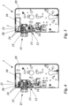
- Eine schematische Darstellung eines ersten erfindungsgemäßen Ausführungsbeispiels des Schlosses mit elektronischem Zusatzmodul mit Blockierelement und Elektronikmodul-Blockierelement in einer Blockierstellung;
- Fig. 3:
- Schloss aus
Fig. 2 mit elektronischem Zusatzmodul mit Blockierelement und Elektronikmodul-Blockierelement in einer Freigabestellung; - Fig. 4:
- Schloss aus
Fig. 2 mit elektronischem Zusatzmodul mit Blockierelement in der Blockierstellung und Elektronikmodul-Blockierelement in der Freigabestellung; - Fig. 5:
- Schloss aus
Fig. 2 mit elektronischem Zusatzmodul mit Blockierelement in der Freigabestellung und Elektronikmodul-Blockierelement in der Blockierstellung; - Fig. 6:
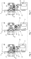
- Eine schematische Darstellung eines zweiten erfindungsgemäßen Ausführungsbeispiels des Schlosses mit elektronischem Zusatzmodul in der Blockierstellung durch das Blockierelement;
- Fig. 7:
- Schloss aus
Fig. 6 mit elektronischem Zusatzmodul in der Freigabestellung durch das Blockierelement und das Elektronikmodul-Blockierelement; - Fig. 8:
- Schloss aus
Fig. 6 mit elektronischem Zusatzmodul in der Blockierstellung durch das Elektronikmodul-Blockierelement.
- Fig.1:
- A schematic representation of a door with a lock;
- Fig. 2:
- A schematic representation of a first embodiment of the lock according to the invention with additional electronic module with blocking element and electronic module blocking element in a blocking position;
- Fig. 3:
- Castle from
Fig.2 with additional electronic module with blocking element and electronic module blocking element in a release position; - Fig.4:
- Castle from
Fig.2 with additional electronic module with blocking element in the blocking position and electronic module blocking element in the release position; - Fig.5:
- Castle from
Fig.2 with additional electronic module with blocking element in the release position and electronic module blocking element in the blocking position; - Fig.6:
- A schematic representation of a second embodiment of the lock according to the invention with additional electronic module in the blocking position by the blocking element;
- Fig.7:
- Castle from
Fig.6 with additional electronic module in the release position through the blocking element and the electronic module blocking element; - Fig.8:
- Castle from
Fig.6 with additional electronic module in the blocking position by the electronic module blocking element.
Das Schloss 1 weist ein Schlossgehäuse 10 auf mit einer darin angeordneten Schlossmechanik und der sperrbaren Schlossfalle 11. Die Schlossfalle 11 ist im Ausführungsbeispiel der
In dem Schlossgehäuse 10 ist ein von der Schlossmechanik bewegbares Blockierelement 12 angeordnet. Im Ausführungsbeispiel der
Im Ausführungsbeispiel der
In
In der Blockierstellung des Blockierelements 12 in
Dies gilt in gleicher Weise für das Elektronikmodul-Blockierelement 20 in
Die Überführung des Blockierelements 12 in die Freigabestellung erfolgt in diesem Ausführungsbeispiel durch die Schlossmechanik. Die Überführung des Elektronikmodul-Blockierelements 20 in die Freigabestellung erfolgt in diesem Ausführungsbeispiel durch einen Antrieb des elektronischen Zusatzmoduls 2.In this embodiment, the blocking
In der Freigabestellung des Blockierelements 12 hintergreifen die Blockierschieber-Rollen 14 auf dem Blockierschieber 13 die Schlossfalle 11 nicht, wie in
Dies gilt in gleicher Weise für das Elektronikmodul-Blockierelement 20. In der Freigabestellung des Elektronikmodul-Blockierelements 20 hintergreifen die Elektronikmodul-Blockierschieber-Rollen 24 auf dem Elektronikmodul-Blockierschieber 23 die Schlossfalle 11 nicht, wie in
Eine Blockierung der Schlossfalle 11 kann entweder nur durch das Blockierelement 12 (
Das Schloss 1 in
In dem Schlossgehäuse 10 ist ein von der Schlossmechanik bewegbares Blockierelement 12 angeordnet. Im Ausführungsbeispiel der
Weiter ist in dem Schlossgehäuse 10 das elektronische Zusatzmodul 2 angeordnet, welches das Elektronikmodul-Verlagerungselement 25 aufweist. Das Elektronikmodul-Verlagerungselement 25 ist im Ausführungsbeispiel der
In
In der Blockierstellung des Blockierelements 12 in
Wenn das Blockierelement 12 in Freigabestellung ist, indem das Elektronikmodul-Blockierelement 20 die Bewegung Schlossmechanik erlaubt, kann die Schlossfalle 11 in das Schlossgehäuse 10 eingeschoben werden. In der Freigabestellung des Blockierelements 12 hintergreifen die Blockierschieber-Rollen 14 auf dem Blockierschieber 13 die Schlossfalle 11 nicht, wie in
Elektronikmodul-Verlagerungselement 25 die Bewegung der Schlossmechanik aus, indem das als Arm ausgebildete Elektronikmodul-Verlagerungselement 25 weiter aus dem Gehäuse des Elektronikmodul-Verlagerungselements 25 herausgeschoben wird. Dies kann durch einen Antrieb des elektronischen Zusatzmoduls 2 erfolgen, oder indem das Elektronikmodul-Verlagerungselement 25 in diesem Fall frei bewegbar im elektronischen Zusatzmodul 2 gelagert angeordnet ist.Electronic
Eine Blockierung der Schlossfalle 11 kann in diesem Ausführungsbeispiel entweder durch das Erlauben der Bewegung der Schlossmechanik auf das Blockierelement 12 (
- 11
- SchlossLock
- 22
- elektronisches Zusatzmoduladditional electronic module
- 33
- Türdoor
- 44
- RahmenFrame
- 1010
- SchlossgehäuseLock housing
- 1111
- SchlossfalleLock latch
- 1212
- BlockierelementBlocking element
- 1313
- BlockierschieberBlocking slide
- 1414
- Blockierschieber-RollenBlocking slide rollers
- 1515
- FallenträgerTrap carrier
- 1616
- FederFeather
- 1717
- KippfalleTipping trap
- 2020
- Elektronikmodul-BlockierelementElectronic module blocking element
- 2323
- Elektronikmodul-BlockierschieberElectronic module blocking slide
- 2424
- Elektronikmodul-Blockierschieber-RollenElectronic module blocking slide rollers
- 2525
- Elektronikmodul-VerlagerungselementElectronic module displacement element
Claims (15)
dadurch gekennzeichnet,
dass das Elektronikmodul-Blockierelement (20) durch einen Antrieb des Elektronikmoduls in eine Blockierstellung verlagerbar ist, in der das Elektronikmodul-Blockierelement (20) die Schlossfalle (11) hintergreift und eine Bewegung der Schlossfalle (11) blockiert ist, und wobei das Elektronikmodul-Blockierelement (20) durch den Antrieb des Elektronikmoduls in eine Freigabestellung verlagerbar ist, in der die Schlossfalle (11) verschwenkbar und translational verschiebbar ist.Lock (1) according to claim 1,
characterized,
that the electronic module blocking element (20) can be displaced by a drive of the electronic module into a blocking position in which the electronic module blocking element (20) engages behind the lock latch (11) and a movement of the lock latch (11) is blocked, and wherein the electronic module blocking element (20) can be displaced by the drive of the electronic module into a release position in which the lock latch (11) can be pivoted and translationally displaced.
dadurch gekennzeichnet,
dass das elektronische Zusatzmodul (2) als Antrieb einen Motor, vorzugweise einen Elektromotor oder eine Spule aufweist.Lock (1) according to one of claims 1 or 2,
characterized,
that the additional electronic module (2) has a motor, preferably an electric motor or a coil, as a drive.
dadurch gekennzeichnet,
dass das Blockierelement (12) und/oder das Elektronikmodul-Blockierelement (20) als ein linear verschiebbar gelagerter Blockierschieber (13) und/oder Elektronikmodul-Blockierschieber (23) ausgebildet sind oder einen linear verschiebbar gelagerten Blockierschieber (13) und/oder Elektronikmodul-Blockierschieber (23) aufweisen.Lock (1) according to one of claims 1 to 3,
characterized,
that the blocking element (12) and/or the electronic module blocking element (20) are designed as a linearly displaceably mounted blocking slide (13) and/or electronic module blocking slide (23) or have a linearly displaceably mounted blocking slide (13) and/or electronic module blocking slide (23).
dadurch gekennzeichnet,
dass das Blockierelement (12) und/oder das Elektronikmodul-Blockierelement (20) als ein drehbar gelagertes Element ausgebildet sind, welches einen Blockier-Abschnitt aufweist, der wahlweise in den Bewegungsbereich der Schlossfalle (11) hineingeschwenkt oder aus diesem herausgeschwenkt werden kann.Lock (1) according to one of claims 1 to 4,
characterized,
that the blocking element (12) and/or the electronic module blocking element (20) are designed as a rotatably mounted element, which has a blocking section that can be optionally pivoted into or out of the movement range of the lock latch (11).
dadurch gekennzeichnet,
dass das Blockierelement (12) und/oder das Elektronikmodul-Blockierelement (20) senkrecht zur Bewegung der Schlossfalle (11) gelagert ausgebildet ist/sind.Lock (1) according to one of claims 1 to 5,
characterized,
that the blocking element (12) and/or the electronic module blocking element (20) is/are mounted perpendicular to the movement of the lock latch (11).
dadurch gekennzeichnet,
dass an dem Blockierelement (12) und/oder dem Elektronikmodul-Blockierelement (20), vorzugsweise am Blockierschieber (13) und/oder am Elektronikmodul-Blockierschieber (23), jeweils zwei Rollen drehbar gelagert ausgebildet sind, wobei die Lagerachsen der jeweils beiden Rollen zueinander parallel sind, und wobei sich die beiden Rollen gegenseitig kontaktieren.Lock (1) according to one of claims 1 to 6,
characterized,
that two rollers are each rotatably mounted on the blocking element (12) and/or the electronic module blocking element (20), preferably on the blocking slide (13) and/or on the electronic module blocking slide (23), wherein the bearing axes of the two rollers are parallel to one another, and wherein the two rollers contact one another.
dadurch gekennzeichnet,
dass das Verlagerungselement (25) eine schaltbare Arretierung zwischen der Schlossmechanik und dem Blockierelement (12) ausbildet, wobei bei erlaubter Übertragung der Bewegung die Arretierung zwischen der Schlossmechanik und dem Blockierelement (12) ausgebildet ist und bei einer verhinderten Übertragung der Bewegung die Arretierung zwischen der Schlossmechanik und dem Blockierelement (12) gelöst ist.Lock (1) according to one of claims 1 to 7,
characterized,
that the displacement element (25) forms a switchable locking mechanism between the lock mechanism and the blocking element (12), wherein when the transmission of the movement is permitted, the locking mechanism is formed between the lock mechanism and the blocking element (12) and when the transmission of the movement is prevented, the locking mechanism between the lock mechanism and the blocking element (12) is released.
dadurch gekennzeichnet,
dass das Blockierelement (12) durch eine Feder in Richtung zur Blockierstellung hin beaufschlagt wird. In einer derartigen Ausgestaltung ist das Blockierelement (12) durch Entkopplung zur Schlossmechanik in der Blockierstellung und kann durch das schaltbare Verlagerungselement (25) durch Koppelung mit der Schlossmechanik in die Freigabestellung überführt werden.Lock (1) according to one of claims 1 to 8,
characterized,
that the blocking element (12) is urged towards the blocking position by a spring. In such an embodiment, the blocking element (12) is in the blocking position by decoupling from the lock mechanism and can be transferred into the release position by the switchable displacement element (25) by coupling to the lock mechanism.
dadurch gekennzeichnet,
dass das Verlagerungselement (25) derart ausgebildet ist, dass bei einer erlaubten Übertragung der Bewegung die Verlagerung des Blockierelements (12) durch die Schlossmechanik nicht kompensiert wird und bei einer verhinderten Übertragung der Bewegung die Verlagerung des Blockierelements (12) durch die Schlossmechanik kompensiert wird, wobei die Kompensation durch eine Bewegung des Verlagerungselements (25) im elektronischen Zusatzmodul (2) erfolgt.Lock (1) according to one of claims 1 to 9,
characterized,
that the displacement element (25) is designed such that when the transmission of the movement is permitted, the displacement of the blocking element (12) is not compensated by the lock mechanism and when the transmission of the movement is prevented, the displacement of the blocking element (12) is compensated by the lock mechanism, wherein the compensation takes place by a movement of the displacement element (25) in the additional electronic module (2).
dadurch gekennzeichnet,
dass das elektronische Zusatzmodul (2) am Schlossgehäuse (10), vorzugsweise Schlossboden angeordnet ist.Lock (1) according to one of claims 1 to 10,
characterized,
that the additional electronic module (2) is arranged on the lock housing (10), preferably the lock base.
dadurch gekennzeichnet,
dass das Schloss ein Steuerfalle aufweist, und eine die Steuerfalle beaufschlagende Feder und wenigstens ein von der Steuerfalle betätigbares Getriebeelement zur Verbindung der Steuerfalle mit der Schlossmechanik.Lock (1) according to one of claims 1 to 11,
characterized,
that the lock has a control latch, and a spring acting on the control latch and at least one gear element actuable by the control latch for connecting the control latch to the lock mechanism.
dadurch gekennzeichnet,
dass das elektronische Zusatzmodul (2) mit einer Stromversorgungsleitung und/oder Steuerleitung verbunden ist.Lock (1) according to one of claims 1 to 3,
characterized,
that the additional electronic module (2) is connected to a power supply line and/or control line.
dadurch gekennzeichnet,
dass das Blockierelement (12) und/oder das Elektronikmodul-Blockierelement (20) linear verschoben werden um zwischen der Blockierstellung und der Freigabestellung zu wechseln, vorzugsweise dass ein Blockierschieber (13) des Blockierelements (12) und/oder ein Elektronikmodul-Blockierschieber (23) des Elektronikmodul-Blockierelements (20) linear verschoben werden um zwischen der Blockierstellung und der Freigabestellung zu wechseln, und/oder dass das Blockierelement (12) und/oder das Elektronikmodul-Blockierelement (20) gedreht werden, wobei das Blockierelement (12) und/oder das Elektronikmodul-Blockierelement (20) als ein drehbar gelagertes Element ausgebildet sind, welches einen Blockier-Abschnitt aufweist, der wahlweise in den Bewegungsbereich der Schlossfalle (11) hineingeschwenkt oder aus diesem herausgeschwenkt wird, und/oder dass die Kompensation der Übertragung der Bewegung durch eine Verschiebung und/oder Drehung des Verlagerungselements (25) erfolgt.Method according to claim 14,
characterized,
that the blocking element (12) and/or the electronic module blocking element (20) are linearly displaced in order to switch between the Blocking position and the release position, preferably that a blocking slide (13) of the blocking element (12) and/or an electronic module blocking slide (23) of the electronic module blocking element (20) are moved linearly in order to change between the blocking position and the release position, and/or that the blocking element (12) and/or the electronic module blocking element (20) are rotated, wherein the blocking element (12) and/or the electronic module blocking element (20) are designed as a rotatably mounted element which has a blocking section which can be selectively pivoted into or out of the movement range of the lock latch (11), and/or that the compensation of the transmission of the movement takes place by a displacement and/or rotation of the displacement element (25).
Applications Claiming Priority (1)
| Application Number | Priority Date | Filing Date | Title |
|---|---|---|---|
| DE102022134993.4A DE102022134993B4 (en) | 2022-12-29 | 2022-12-29 | anti-panic lock with escape door opener |
Publications (1)
| Publication Number | Publication Date |
|---|---|
| EP4397828A1 true EP4397828A1 (en) | 2024-07-10 |
Family
ID=89122141
Family Applications (1)
| Application Number | Title | Priority Date | Filing Date |
|---|---|---|---|
| EP23214500.3A Pending EP4397828A1 (en) | 2022-12-29 | 2023-12-06 | Anti-panic lock with escape door opener |
Country Status (2)
| Country | Link |
|---|---|
| EP (1) | EP4397828A1 (en) |
| DE (1) | DE102022134993B4 (en) |
Citations (4)
| Publication number | Priority date | Publication date | Assignee | Title |
|---|---|---|---|---|
| EP1908899A2 (en) * | 2006-10-05 | 2008-04-09 | S.E.M. Technologies GmbH | Locking system |
| GB2456188A (en) * | 2008-03-26 | 2009-07-08 | Gianni Ind Inc | Lock bolt with powered deadlock |
| WO2013114409A1 (en) | 2012-01-30 | 2013-08-08 | Cisa S.P.A. | Lock for doors |
| EP3299552A1 (en) | 2016-09-26 | 2018-03-28 | ASSA ABLOY (Schweiz) AG | Modular lock |
Family Cites Families (3)
| Publication number | Priority date | Publication date | Assignee | Title |
|---|---|---|---|---|
| FI82287C (en) * | 1987-04-13 | 1991-02-11 | Waertsilae Oy Ab | DOERRLAOS. |
| DE3926132A1 (en) * | 1989-08-08 | 1991-02-14 | Sitec Gmbh Sicherheitseinricht | Safe storage compartment with doors outside and inside secure room - has electrical interlock preventing simultaneous opening of doors and automatic locking without key operation |
| AT9709U1 (en) * | 2007-05-11 | 2008-02-15 | Grundmann Beschlagtechnik Gmbh | LOCK |
-
2022
- 2022-12-29 DE DE102022134993.4A patent/DE102022134993B4/en active Active
-
2023
- 2023-12-06 EP EP23214500.3A patent/EP4397828A1/en active Pending
Patent Citations (4)
| Publication number | Priority date | Publication date | Assignee | Title |
|---|---|---|---|---|
| EP1908899A2 (en) * | 2006-10-05 | 2008-04-09 | S.E.M. Technologies GmbH | Locking system |
| GB2456188A (en) * | 2008-03-26 | 2009-07-08 | Gianni Ind Inc | Lock bolt with powered deadlock |
| WO2013114409A1 (en) | 2012-01-30 | 2013-08-08 | Cisa S.P.A. | Lock for doors |
| EP3299552A1 (en) | 2016-09-26 | 2018-03-28 | ASSA ABLOY (Schweiz) AG | Modular lock |
Also Published As
| Publication number | Publication date |
|---|---|
| DE102022134993B4 (en) | 2025-02-20 |
| DE102022134993A1 (en) | 2024-07-04 |
Similar Documents
| Publication | Publication Date | Title |
|---|---|---|
| EP1832700B1 (en) | Locking system for a door | |
| EP0073964B1 (en) | Door with a locking device | |
| EP3299552B1 (en) | Modular lock | |
| EP3406832B1 (en) | Keeper for a panic door lock | |
| DE3620799A1 (en) | Multi-function mortise lock | |
| EP1733111B1 (en) | Window or door comprising an electromechanical locking mechanism | |
| EP2339096B1 (en) | Connecting rod lock with panic function and multiple locking | |
| EP1740792B1 (en) | Turn-tilt window | |
| DE29619007U1 (en) | Locking device | |
| DE102022134993B4 (en) | anti-panic lock with escape door opener | |
| EP3611317B1 (en) | Actuating gear for displacing a drive rod of a window or a door | |
| DE19900875C2 (en) | Locking device for a door system | |
| EP3219887B1 (en) | Universal anti-panic pressure rod | |
| EP0885340A1 (en) | Locking device for a wing, in particular a door with a plurality of locking bolts | |
| EP2998475B1 (en) | Day lever for a passive leaf lock | |
| DE19944050A1 (en) | Locking device for windows and doors has rotary bolt brought into closing position by movement of operating unit which is automatically initiated during closing movement of door | |
| EP3655601B1 (en) | Lock | |
| EP4206429B1 (en) | Self-locking lock with motorised unlocking | |
| EP4617454A1 (en) | Espag bolt lock | |
| EP1132554A2 (en) | Door opener | |
| EP4624705A1 (en) | Method for operating an espagnolette lock with central position of a double-leaf dooor and espagnolette lock with central position for double-leaf door | |
| EP4509683A1 (en) | Automatically locking espagnolette lock | |
| DE102012016330B4 (en) | Lock for flaps or doors on vehicles | |
| DE102004040692A1 (en) | Panic door lock for use in flight door, has diverting drive, which couples actuating bar with catching device that supports flight door at barrier counter part in closed condition of door, where catching device is part of inserting lock | |
| EP2162308A1 (en) | Sliding door for a vehicle |
Legal Events
| Date | Code | Title | Description |
|---|---|---|---|
| PUAI | Public reference made under article 153(3) epc to a published international application that has entered the european phase |
Free format text: ORIGINAL CODE: 0009012 |
|
| STAA | Information on the status of an ep patent application or granted ep patent |
Free format text: STATUS: THE APPLICATION HAS BEEN PUBLISHED |
|
| AK | Designated contracting states |
Kind code of ref document: A1 Designated state(s): AL AT BE BG CH CY CZ DE DK EE ES FI FR GB GR HR HU IE IS IT LI LT LU LV MC ME MK MT NL NO PL PT RO RS SE SI SK SM TR |
|
| STAA | Information on the status of an ep patent application or granted ep patent |
Free format text: STATUS: REQUEST FOR EXAMINATION WAS MADE |
|
| 17P | Request for examination filed |
Effective date: 20240816 |
|
| RBV | Designated contracting states (corrected) |
Designated state(s): AL AT BE BG CH CY CZ DE DK EE ES FI FR GB GR HR HU IE IS IT LI LT LU LV MC ME MK MT NL NO PL PT RO RS SE SI SK SM TR |