EP4397606B1 - Vorrichtung zum geordneten laden und entladen von objekten - Google Patents
Vorrichtung zum geordneten laden und entladen von objekten Download PDFInfo
- Publication number
- EP4397606B1 EP4397606B1 EP24150851.4A EP24150851A EP4397606B1 EP 4397606 B1 EP4397606 B1 EP 4397606B1 EP 24150851 A EP24150851 A EP 24150851A EP 4397606 B1 EP4397606 B1 EP 4397606B1
- Authority
- EP
- European Patent Office
- Prior art keywords
- objects
- src
- frc
- mpohcp
- lup
- Prior art date
- Legal status (The legal status is an assumption and is not a legal conclusion. Google has not performed a legal analysis and makes no representation as to the accuracy of the status listed.)
- Active
Links
Images





Classifications
-
- B—PERFORMING OPERATIONS; TRANSPORTING
- B65—CONVEYING; PACKING; STORING; HANDLING THIN OR FILAMENTARY MATERIAL
- B65G—TRANSPORT OR STORAGE DEVICES, e.g. CONVEYORS FOR LOADING OR TIPPING, SHOP CONVEYOR SYSTEMS OR PNEUMATIC TUBE CONVEYORS
- B65G67/00—Loading or unloading vehicles
- B65G67/02—Loading or unloading land vehicles
- B65G67/04—Loading land vehicles
- B65G67/20—Loading covered vehicles
-
- B—PERFORMING OPERATIONS; TRANSPORTING
- B65—CONVEYING; PACKING; STORING; HANDLING THIN OR FILAMENTARY MATERIAL
- B65G—TRANSPORT OR STORAGE DEVICES, e.g. CONVEYORS FOR LOADING OR TIPPING, SHOP CONVEYOR SYSTEMS OR PNEUMATIC TUBE CONVEYORS
- B65G61/00—Use of pick-up or transfer devices or of manipulators for stacking or de-stacking articles not otherwise provided for
-
- B—PERFORMING OPERATIONS; TRANSPORTING
- B65—CONVEYING; PACKING; STORING; HANDLING THIN OR FILAMENTARY MATERIAL
- B65G—TRANSPORT OR STORAGE DEVICES, e.g. CONVEYORS FOR LOADING OR TIPPING, SHOP CONVEYOR SYSTEMS OR PNEUMATIC TUBE CONVEYORS
- B65G47/00—Article or material-handling devices associated with conveyors; Methods employing such devices
- B65G47/74—Feeding, transfer, or discharging devices of particular kinds or types
- B65G47/90—Devices for picking-up and depositing articles or materials
- B65G47/91—Devices for picking-up and depositing articles or materials incorporating pneumatic, e.g. suction, grippers
-
- B—PERFORMING OPERATIONS; TRANSPORTING
- B65—CONVEYING; PACKING; STORING; HANDLING THIN OR FILAMENTARY MATERIAL
- B65G—TRANSPORT OR STORAGE DEVICES, e.g. CONVEYORS FOR LOADING OR TIPPING, SHOP CONVEYOR SYSTEMS OR PNEUMATIC TUBE CONVEYORS
- B65G67/00—Loading or unloading vehicles
- B65G67/02—Loading or unloading land vehicles
- B65G67/24—Unloading land vehicles
-
- B—PERFORMING OPERATIONS; TRANSPORTING
- B65—CONVEYING; PACKING; STORING; HANDLING THIN OR FILAMENTARY MATERIAL
- B65G—TRANSPORT OR STORAGE DEVICES, e.g. CONVEYORS FOR LOADING OR TIPPING, SHOP CONVEYOR SYSTEMS OR PNEUMATIC TUBE CONVEYORS
- B65G2203/00—Indexing code relating to control or detection of the articles or the load carriers during conveying
- B65G2203/04—Detection means
- B65G2203/041—Camera
-
- B—PERFORMING OPERATIONS; TRANSPORTING
- B65—CONVEYING; PACKING; STORING; HANDLING THIN OR FILAMENTARY MATERIAL
- B65G—TRANSPORT OR STORAGE DEVICES, e.g. CONVEYORS FOR LOADING OR TIPPING, SHOP CONVEYOR SYSTEMS OR PNEUMATIC TUBE CONVEYORS
- B65G67/00—Loading or unloading vehicles
- B65G67/02—Loading or unloading land vehicles
Definitions
- Embodiments of the present disclosure present technological improvements as solutions to one or more of the above-mentioned technical problems recognized by the inventors in conventional systems.
- the first m-axis collaborative manipulator (FMACM) is mounted on the first end of the FRC, and the second m-axis collaborative manipulator (SMACM) is mounted on the second end of the SRC, respectively.
- the apparatus further comprises a jack system that is connected underneath the UDS.
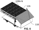
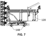
- FIGS. 1 through 16 Reference numerals of one or more components of the apparatus as depicted in the FIGS. 1 through 16 are provided in Table 1 below for ease of description: Table 1 Sl.
- the apparatus 100 further comprises a unit drive system (UDS) 114.
- the UDS 114 moves the LUP 102 and the MPOHCP 104 in one or more directions based on a first operation, and/or a second operation respectively being performed by the apparatus 100.
- FIG. 4 illustrates the apparatus 100 with the unit drive system 112, in accordance with an embodiment of the present disclosure.
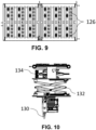
- the apparatus 100 further comprises one or more vacuum generators 130 that are configured to generate vacuum for the plurality of suction panels 128A-N.
- FIG. 10 illustrates a portion of the apparatus 100 depicting the one or more vacuum generators 130, in accordance with an embodiment of the present disclosure.
- the one or more vacuum generators 130 generate enough vacuum for all the suction panels in the plurality of OGSs 126.
- the generated vacuum is distributed through one or more main lines (e.g., 4 main lines in the present disclosure). There are 5 such vacuum generators (not shown in FIGS.) for the entire apparatus 100.
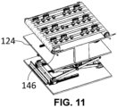
- each OGCS 122A-N comprises one or more vision cameras 146 (e.g., refer FIG. 11 ), and the like.
- FIG. 11 illustrates a portion of the apparatus depicting the object gripping and conveying system (OGCS) having the vision camera 146, in accordance with an embodiment of the present disclosure.
- the one or more vision cameras 146 (also referred as vision system and interchangeably used herein) are used to find distance from the OGS 126 to objects which are loaded on/within an environment (e.g., container).
- the vision cameras 146 pass the command to adjust the height of object gripping panel lift mechanism 132 on which the vision cameras 146 are mounted.
- One or more motors connected to the FRC and the SRC respectively are configured to rotate one or more associated rollers in the fourth direction (CCW) to enable placement of the one or more objects on the MPOHCP 104.
- the one or more motors connected to the FRC and the SRC enable rotation of rollers of the FRC and the SRC in the fourth direction.
- the SMACM picks and places the one or more objects from an initial position on to the SRC. This ensures that the one or more objects are uniformly distributed by the FMACM based on a size of the one or more objects and space available on the MPOHCP 104.
- the above unloading operation is better understood by way of following description: At first, based on the vision input the suction panels are positioned individually using OGPLM 132 with respect to the distance of objects from the OGS 126. All the objects are then gripped in bulk by the suction panels, while the SLM 134 is in lowered position, exposing the suction cups of the panels 128A-N. The MPOHCP 104 is then pushed slightly forward by the UDS 114 to stabilize the next layer. The drive mechanism 112 rotates MPOHCP 104 by 90 degrees clockwise so that gripped objects are ready for getting conveyed out. The SLM 134 now lifts and the OGS 126 releases vacuum, so all the objects now rest on the SBC 124.
- the SBC 124 rotates in clockwise and all the objects over the SBC belts convey them towards the BC 118 and are made to converge towards the FRC 106A. Any misplaced object is gripped and placed properly by FMACM 116A and are conveyed from the FRC 106A to the SRC 106B. At the end of SRC 106B the SMACM 116B picks the objects and places either on pallet or container in the required pattern.
- the MPOHCP 104 is rotated CW by 90 degrees and the apparatus 100 is moved to the next layer by the UDS 14 thus ensuring the objects are unloaded and organized in a specific manner in a given environment (or constrained space/open area/container, etc.). The above steps are repeated from the first layer till inner most portion of the container.
Landscapes
- Engineering & Computer Science (AREA)
- Mechanical Engineering (AREA)
- Aviation & Aerospace Engineering (AREA)
- Specific Conveyance Elements (AREA)
- Manipulator (AREA)
Claims (10)
- Vorrichtung (100) zum organisierten Laden und Entladen einer Mehrzahl von Objekten, umfassend:eine Lade- und Entladeplattform (LUP) (102);eine Multi-Panel-Objekthalte- und -förderplattform (MPOHCP) (104), die mit der LUP (102) verbunden ist;einen ersten Rollenförderer (FRC) (106A) und einen zweiten Rollenförderer (SRC) (106B), die an der LUP angebracht sind, wobei der FRC (106A) und der SRC (106B) jeweils ein erstes Ende und ein zweites Ende umfassen, wobei das zweite Ende des FRC (106A) mit dem ersten Ende des SRC (106B) verbunden ist, und wobei der FRC (106A) und der SRC (106B) jeweils eine Mehrzahl von Rollen (108A-N) an einer Mehrzahl von Laufrollenbeinen (110A-N) umfassen;einen Antriebsmechanismus (112), der mit der LUP (102) und der MPOHCP (104) verbunden ist, wobei der Antriebsmechanismus (112) konfiguriert ist, um die MPOHCP (104) aus einer ersten Richtung in eine zweite Richtung zu drehen;ein Einheitsantriebssystem (UDS) (114), das konfiguriert ist, um die LUP (102) und die MPOHCP (104) basierend auf mindestens einem von einem ersten Vorgang und einem zweiten Vorgang, die von der Vorrichtung (100) durchgeführt werden, in eine oder mehrere Richtungen zu bewegen;einen ersten kollaborativen m-Achsen-Manipulator (FMACM) (116A) und einen zweiten kollaborativen m-Achsen-Manipulator (SMACM) (116B), die jeweils an dem FRC (106A) und dem SRC (106B) angebracht sind;einen Brückenförderer (BC) (118), der mit dem ersten Ende des FRC (106A) verbunden ist;einen Platzierungsaktuator (120), der konfiguriert ist, um den BC (118) anzuheben und abzusenken;ein oder mehrere Objektgreif- und fördersysteme (OGCS) (122A-N), wobei jedes der OGCS (122A-N) einen geteilten Bandförderer (SBC) (124) umfasst, und wobei der SBC (124) von einem Trommelmotor betrieben und von einem geteilten Bandhebemechanismus (SLM) (134) angehoben und abgesenkt wird;ein oder mehrere Objektgreifsysteme (OGS) (126), die jeweils an dem einen oder den mehreren OGCS (122A-N) angebracht sind, wobei jedes des einen oder der mehreren OGS (126) eine Mehrzahl von Saugplatten (128A-N) umfasst;einen oder mehrere Vakuumgeneratoren (130), die konfiguriert sind, um Vakuum für die Mehrzahl von Saugplatten (128A-N) zu erzeugen; undeinen Objektgreifplattenhebemechanismus (OGPLM) (132), der konfiguriert ist, um die Mehrzahl von Saugplatten (128A-N) anzuheben oder abzusenken, um mindestens einen von dem ersten Vorgang und dem zweiten Vorgang eines oder mehrerer Objekten von einer ersten Zone zu einer zweiten Zone durchzuführen.
- Vorrichtung nach Anspruch 1, wobei während des ersten Vorgangs und des zweiten Vorgangs ein letztes Laufrollenbein des SRC (106B) in einer ersten Position konfiguriert ist und verbleibende Laufrollenbeine des SRC (106B) und das eine oder die mehreren Laufrollenbeine des FRC (106A) in einer zweiten Position konfiguriert sind.
- Vorrichtung nach Anspruch 1, wobei der Antriebsmechanismus (112) umfasst:ein erstes Verbindungsglied (136), das ein erstes Gelenk (138), ein zweites Gelenk (140) und ein drittes Gelenk (142) umfasst, wobei das erste Gelenk (138) mit einer spezifischen Stelle der MPOHCP (104) verbunden ist und das dritte Gelenk (142) mit einem Drehpunkt verbunden ist, der an der LUP (102) angebracht ist; undein zweites Verbindungsglied (144), das ferner ein erstes Ende und ein zweites Ende umfasst, wobei das erste Ende des zweiten Verbindungsglieds (144) über das zweite Gelenk (140) mit dem ersten Verbindungsglied (136) verbunden ist und das zweite Ende des zweiten Verbindungsglieds (144) mit einer Kurbel verbunden ist, die von einem Motor angetrieben wird, der eine Bremse und einen Encoder umfasst, und wobei der Motor an der LUP (102) angebracht ist.
- Vorrichtung nach Anspruch 1, wobei der FMACM (116A) jeweils an dem ersten Ende des FRC (106A) angebracht ist und der SMACM (116B) an dem zweiten Ende des SRC (106B) angebracht ist.
- Vorrichtung nach Anspruch 1, wobei während des ersten Vorgangsder Antriebsmechanismus (112) konfiguriert ist, um die MPOHCP (104) in eine dritte Richtung zu drehen,der BC (118), der FRC (106A) und der SRC (106B) konfiguriert sind, um sich in eine vierte Richtung zu drehen, um ein oder mehrere Objekte auf der MPOHCP (104) zu fördern,der Platzierungsaktuator (120) konfiguriert ist, um (i) den BC (118) abzusenken und (ii) mindestens ein Ende des FRC (106A) zu verbinden,wobei ein Trommelmotor konfiguriert ist, um die eine oder die mehreren Rollen des BC (118) in die vierte Richtung zu drehen, und wobei ein oder mehrere Motoren, die jeweils mit dem FRC (106A) und dem SRC (106B) verbunden sind, konfiguriert sind, um eine oder mehrere zugehörige Rollen in die vierte Richtung zu drehen, um die Platzierung des einen oder der mehreren Objekte auf der MPOHCP (104) zu ermöglichen,der SMACM (116B) konfiguriert ist, um das eine oder die mehreren Objekte von einer Anfangsposition auf dem SRC (106B) aufzunehmen und zu platzieren, wobei das eine oder die mehreren Objekte durch den FMACM (116A) basierend auf einer Größe des einen oder der mehreren Objekte und dem auf der MPOHCP (104) verfügbaren Platz gleichmäßig verteilt werden,der Antriebsmechanismus (112) konfiguriert ist, um (i) die MPOHCP (104) in die vierte Richtung zu drehen und (ii) Vakuum zum Stapeln des einen oder der mehreren Objekte freizusetzen, und wobei das eine oder die mehreren Objekte durch einen Schiebemechanismus geschoben werden, undder Antriebsmechanismus (112) konfiguriert ist, um die MPOHCP (104) in die dritte Richtung zu drehen, und das UDS (114) konfiguriert ist, um die Vorrichtung für einen nachfolgenden Vorgang in eine spezifische Richtung zu bewegen.
- Vorrichtung nach Anspruch 5, wobei während des zweiten Vorgangsdie Mehrzahl von Saugplatten (128A-N) unter Verwendung des OGPLM (132) basierend auf dem Abstand eines oder mehrerer Objekte von der Mehrzahl von Saugplatten (128A-N) zum Greifen des einen oder der mehreren Objekte positioniert wird, wobei der Abstand des einen oder der mehreren Objekte durch ein Sichtsystem (146) bestimmt wird,die MPOHCP (104) konfiguriert ist, um sich durch das UDS (114) vorwärts zu bewegen,der Antriebsmechanismus (112) konfiguriert ist, um sich in die dritte Richtung zum Platzieren des einen oder der mehreren Objekte von der zweiten Zone zu der ersten Zone zu drehen,die Mehrzahl von Saugplatten (128A-N) Vakuum freisetzt, um Ruhen des einen oder der mehreren Objekte auf dem SBC (124) zu ermöglichen;der OGPLM (132) konfiguriert ist, um den SBC (124) mit dem einen oder den mehreren Objekten zum Platzieren durch den FMACM (116A) von dem BC (118) in Richtung des FRC (106A) und des SRC (106B) anzuheben, undder SMACM (116B) konfiguriert ist, um das eine oder die mehreren Objekte von dem SRC (106B) zum Platzieren an der gewünschten Stelle aufzunehmen, unddas UDS (114) konfiguriert ist, um die Vorrichtung (100) für einen nachfolgenden Vorgang in eine spezifische Richtung zu bewegen.
- Vorrichtung nach Anspruch 1, ferner umfassend eine Plattform (150), die an der LUP (102) angelenkt ist.
- Vorrichtung nach Anspruch 7, wobei während des Transports der Vorrichtung (100) die Plattform (150) als ein Stopper konfiguriert ist.
- Vorrichtung nach Anspruch 7, wobei während eines Aufstellens der Vorrichtung (100) die Plattform (150) in einem spezifischen Winkel konfiguriert ist, um den FRC (106A) und den SRC (106B) auszusteigen.
- Vorrichtung nach Anspruch 1, ferner umfassend ein Hebesystem (148), das unterhalb des UDS (114) verbunden ist, wobei das Hebesystem (148) konfiguriert ist, um die Vorrichtung in Bezug auf eine Bodenoberfläche zu nivellieren und die Vorrichtung in eine gewünschte Position anzuheben.
Applications Claiming Priority (1)
| Application Number | Priority Date | Filing Date | Title |
|---|---|---|---|
| IN202321001854 | 2023-01-09 |
Publications (3)
| Publication Number | Publication Date |
|---|---|
| EP4397606A1 EP4397606A1 (de) | 2024-07-10 |
| EP4397606B1 true EP4397606B1 (de) | 2025-04-16 |
| EP4397606C0 EP4397606C0 (de) | 2025-04-16 |
Family
ID=89542253
Family Applications (1)
| Application Number | Title | Priority Date | Filing Date |
|---|---|---|---|
| EP24150851.4A Active EP4397606B1 (de) | 2023-01-09 | 2024-01-09 | Vorrichtung zum geordneten laden und entladen von objekten |
Country Status (2)
| Country | Link |
|---|---|
| US (1) | US12312188B2 (de) |
| EP (1) | EP4397606B1 (de) |
Family Cites Families (26)
| Publication number | Priority date | Publication date | Assignee | Title |
|---|---|---|---|---|
| US3790003A (en) * | 1972-11-15 | 1974-02-05 | Ace Glass Co | Tiltable glass cutting table |
| US4093083A (en) * | 1975-04-17 | 1978-06-06 | Spiegelglaswerke Germania, Zweigniederlassung Der Glaceries De Saint.Roch S.A. | Apparatus for stacking and unstacking sheet material, more particularly glass sheets |
| FR2636324A1 (fr) * | 1988-09-15 | 1990-03-16 | Sgn Soc Gen Tech Nouvelle | Installation pour le relevage rapide et l'empilage de plaques de verre |
| US5984624A (en) * | 1999-02-19 | 1999-11-16 | Glassline Corporation | Article loader/unloader |
| EP1639512B1 (de) | 2003-06-30 | 2009-10-21 | Kyong-Ja Jung | Verfahren und vorrichtung zum lagern und transferieren von behältern |
| WO2005051813A1 (en) * | 2003-11-26 | 2005-06-09 | Sjoerd Meijer | Loading device comprising an auxiliary transport means |
| DE102010015299A1 (de) * | 2010-04-15 | 2011-10-20 | BIBA - Bremer Institut für Produktion und Logistik GmbH | System zum Handhaben von Stückgütern für das, vorzugsweise automatische, Be- und Entladen eines Laderaumes |
| WO2014113762A1 (en) * | 2013-01-20 | 2014-07-24 | Wynright Corporation | Automated truck unloader for unloading/unpacking product from trailers and containers |
| US9315345B2 (en) * | 2013-08-28 | 2016-04-19 | Intelligrated Headquarters Llc | Robotic carton unloader |
| JP6325398B2 (ja) * | 2014-09-10 | 2018-05-16 | 株式会社東芝 | 荷役装置及び把持装置 |
| KR20170097982A (ko) | 2016-02-19 | 2017-08-29 | 윤호섭 | 컨테이너의 이/적재가 가능한 2중 모드 트레일러 |
| CN109715536B (zh) * | 2016-09-14 | 2021-04-30 | 因特利格雷特总部有限责任公司 | 机器人纸箱卸载机 |
| US10099867B2 (en) * | 2016-11-15 | 2018-10-16 | Amazon Technologies, Inc. | Automated package unloading system |
| WO2020243749A1 (en) * | 2019-05-31 | 2020-12-03 | Bastian Solutions, Llc | Automated unloading and loading robot system with telescoping mast and z-axis control |
| JP7580910B2 (ja) * | 2019-11-14 | 2024-11-12 | 株式会社東芝 | 荷役装置 |
| CN110683368A (zh) | 2019-11-15 | 2020-01-14 | 徐州工程学院 | 一种适用于集装箱内货物的智能化装卸和堆垛一体机 |
| CN111232680A (zh) * | 2020-03-16 | 2020-06-05 | 湖南金能自动化设备有限公司 | 一种悬臂式装卸输送装置 |
| EP3885292B1 (de) * | 2020-03-27 | 2023-05-03 | Tata Consultancy Services Limited | Vorrichtung und verfahren zum automatischen handhaben von gegenständen auf und von paletten |
| CN113800282A (zh) | 2020-06-17 | 2021-12-17 | 阳程科技股份有限公司 | 板片移载机的集尘机构 |
| CN111776941B (zh) | 2020-07-13 | 2021-12-21 | 福建省港航勘察设计院有限公司 | 立体式自动化集装箱码头的总体布置和装卸工艺 |
| CN112278911B (zh) | 2020-08-03 | 2023-05-02 | 北京京东乾石科技有限公司 | 装卸货设备以及装卸货系统 |
| CN111847004A (zh) * | 2020-08-20 | 2020-10-30 | 成都云麒智能科技有限公司 | 一种基于视觉伺服的智能装卸车系统 |
| CN112124987A (zh) | 2020-09-07 | 2020-12-25 | 苗林展 | 一种集装箱运输装卸系统及方法 |
| WO2022047781A1 (zh) | 2020-09-07 | 2022-03-10 | 苗林展 | 一种集装箱运输装卸系统及方法 |
| CN113291774B (zh) | 2021-06-30 | 2021-12-17 | 青岛科捷机器人有限公司 | 装卸货一体机及集装箱自动装卸货系统 |
| CN114261669B (zh) | 2021-12-03 | 2022-09-23 | 中车唐山机车车辆有限公司 | 一种轨道交通智能装卸系统及轨道车辆 |
-
2024
- 2024-01-09 EP EP24150851.4A patent/EP4397606B1/de active Active
- 2024-01-09 US US18/407,948 patent/US12312188B2/en active Active
Also Published As
| Publication number | Publication date |
|---|---|
| US12312188B2 (en) | 2025-05-27 |
| US20240228196A1 (en) | 2024-07-11 |
| EP4397606A1 (de) | 2024-07-10 |
| EP4397606C0 (de) | 2025-04-16 |
Similar Documents
| Publication | Publication Date | Title |
|---|---|---|
| US11427414B2 (en) | System and method for palletizing | |
| JP7163367B2 (ja) | トート及びサブトート運搬用のユニバーサルグリッパ | |
| US11254515B2 (en) | Cargo handling apparatus | |
| JP7127830B2 (ja) | パレタイザ用ハンド、パレタイザシステム、及び、デパレ・パレタイジング方法 | |
| CN113135408B (zh) | 一种货箱转移系统、方法、货箱转移装置和机器人 | |
| EP3636566B1 (de) | Vorrichtung zum be- und entladen von fracht | |
| CN110239966A (zh) | 一种紧凑型装卸货移动机器人及装货和卸货方法 | |
| JPH06502461A (ja) | 移載装置,多階層保管システムおよび積載物の持上方法 | |
| CN110482270B (zh) | 货物装载方法 | |
| US12391489B2 (en) | Interoperable robotic system to load/unload trucks and other containers | |
| KR20100056777A (ko) | 완제품 타이어의 이동 적재장치 | |
| US12312188B2 (en) | Apparatus for organized loading, and unloading of objects | |
| CN217436998U (zh) | 货箱输送系统 | |
| JP2019119553A (ja) | 物品搬送設備 | |
| JP2020075791A (ja) | 箱体積付システム | |
| CN118331203B (zh) | 一种天窗顺建控制方法及系统 | |
| KR20130031783A (ko) | 통합 운반 장치 및 이를 이용한 방법 | |
| CN113044322B (zh) | 制剂灭菌物流系统及制剂灭菌方法 | |
| US10926500B2 (en) | Method and device for handling tires | |
| TW202332646A (zh) | 容器處理設備 | |
| JPH0692470A (ja) | トラックローダ | |
| WO2018097139A1 (ja) | 物品移載装置(article transfer device) | |
| JPS61217410A (ja) | 立体倉庫における入出庫方法及びスタツカクレ−ン | |
| CN220722299U (zh) | 仓储系统 | |
| JP7533677B2 (ja) | 移載装置 |
Legal Events
| Date | Code | Title | Description |
|---|---|---|---|
| PUAI | Public reference made under article 153(3) epc to a published international application that has entered the european phase |
Free format text: ORIGINAL CODE: 0009012 |
|
| STAA | Information on the status of an ep patent application or granted ep patent |
Free format text: STATUS: REQUEST FOR EXAMINATION WAS MADE |
|
| 17P | Request for examination filed |
Effective date: 20240606 |
|
| AK | Designated contracting states |
Kind code of ref document: A1 Designated state(s): AL AT BE BG CH CY CZ DE DK EE ES FI FR GB GR HR HU IE IS IT LI LT LU LV MC ME MK MT NL NO PL PT RO RS SE SI SK SM TR |
|
| GRAP | Despatch of communication of intention to grant a patent |
Free format text: ORIGINAL CODE: EPIDOSNIGR1 |
|
| STAA | Information on the status of an ep patent application or granted ep patent |
Free format text: STATUS: GRANT OF PATENT IS INTENDED |
|
| INTG | Intention to grant announced |
Effective date: 20241216 |
|
| GRAS | Grant fee paid |
Free format text: ORIGINAL CODE: EPIDOSNIGR3 |
|
| GRAA | (expected) grant |
Free format text: ORIGINAL CODE: 0009210 |
|
| STAA | Information on the status of an ep patent application or granted ep patent |
Free format text: STATUS: THE PATENT HAS BEEN GRANTED |
|
| AK | Designated contracting states |
Kind code of ref document: B1 Designated state(s): AL AT BE BG CH CY CZ DE DK EE ES FI FR GB GR HR HU IE IS IT LI LT LU LV MC ME MK MT NL NO PL PT RO RS SE SI SK SM TR |
|
| REG | Reference to a national code |
Ref country code: GB Ref legal event code: FG4D |
|
| REG | Reference to a national code |
Ref country code: CH Ref legal event code: EP |
|
| REG | Reference to a national code |
Ref country code: IE Ref legal event code: FG4D |
|
| U01 | Request for unitary effect filed |
Effective date: 20250416 |
|
| U07 | Unitary effect registered |
Designated state(s): AT BE BG DE DK EE FI FR IT LT LU LV MT NL PT RO SE SI Effective date: 20250424 |
|
| PG25 | Lapsed in a contracting state [announced via postgrant information from national office to epo] |
Ref country code: ES Free format text: LAPSE BECAUSE OF FAILURE TO SUBMIT A TRANSLATION OF THE DESCRIPTION OR TO PAY THE FEE WITHIN THE PRESCRIBED TIME-LIMIT Effective date: 20250416 |
|
| PG25 | Lapsed in a contracting state [announced via postgrant information from national office to epo] |
Ref country code: NO Free format text: LAPSE BECAUSE OF FAILURE TO SUBMIT A TRANSLATION OF THE DESCRIPTION OR TO PAY THE FEE WITHIN THE PRESCRIBED TIME-LIMIT Effective date: 20250716 Ref country code: GR Free format text: LAPSE BECAUSE OF FAILURE TO SUBMIT A TRANSLATION OF THE DESCRIPTION OR TO PAY THE FEE WITHIN THE PRESCRIBED TIME-LIMIT Effective date: 20250717 |
|
| PG25 | Lapsed in a contracting state [announced via postgrant information from national office to epo] |
Ref country code: PL Free format text: LAPSE BECAUSE OF FAILURE TO SUBMIT A TRANSLATION OF THE DESCRIPTION OR TO PAY THE FEE WITHIN THE PRESCRIBED TIME-LIMIT Effective date: 20250416 |
|
| PG25 | Lapsed in a contracting state [announced via postgrant information from national office to epo] |
Ref country code: HR Free format text: LAPSE BECAUSE OF FAILURE TO SUBMIT A TRANSLATION OF THE DESCRIPTION OR TO PAY THE FEE WITHIN THE PRESCRIBED TIME-LIMIT Effective date: 20250416 |
|
| PG25 | Lapsed in a contracting state [announced via postgrant information from national office to epo] |
Ref country code: RS Free format text: LAPSE BECAUSE OF FAILURE TO SUBMIT A TRANSLATION OF THE DESCRIPTION OR TO PAY THE FEE WITHIN THE PRESCRIBED TIME-LIMIT Effective date: 20250716 |
|
| PG25 | Lapsed in a contracting state [announced via postgrant information from national office to epo] |
Ref country code: IS Free format text: LAPSE BECAUSE OF FAILURE TO SUBMIT A TRANSLATION OF THE DESCRIPTION OR TO PAY THE FEE WITHIN THE PRESCRIBED TIME-LIMIT Effective date: 20250816 |
|
| PG25 | Lapsed in a contracting state [announced via postgrant information from national office to epo] |
Ref country code: SM Free format text: LAPSE BECAUSE OF FAILURE TO SUBMIT A TRANSLATION OF THE DESCRIPTION OR TO PAY THE FEE WITHIN THE PRESCRIBED TIME-LIMIT Effective date: 20250416 |
|
| PG25 | Lapsed in a contracting state [announced via postgrant information from national office to epo] |
Ref country code: CZ Free format text: LAPSE BECAUSE OF FAILURE TO SUBMIT A TRANSLATION OF THE DESCRIPTION OR TO PAY THE FEE WITHIN THE PRESCRIBED TIME-LIMIT Effective date: 20250416 |
|
| PG25 | Lapsed in a contracting state [announced via postgrant information from national office to epo] |
Ref country code: SK Free format text: LAPSE BECAUSE OF FAILURE TO SUBMIT A TRANSLATION OF THE DESCRIPTION OR TO PAY THE FEE WITHIN THE PRESCRIBED TIME-LIMIT Effective date: 20250416 |
|
| PLBE | No opposition filed within time limit |
Free format text: ORIGINAL CODE: 0009261 |
|
| STAA | Information on the status of an ep patent application or granted ep patent |
Free format text: STATUS: NO OPPOSITION FILED WITHIN TIME LIMIT |
|
| REG | Reference to a national code |
Ref country code: CH Ref legal event code: L10 Free format text: ST27 STATUS EVENT CODE: U-0-0-L10-L00 (AS PROVIDED BY THE NATIONAL OFFICE) Effective date: 20260225 |
|
| U20 | Renewal fee for the european patent with unitary effect paid |
Year of fee payment: 3 Effective date: 20260126 |
|
| 26N | No opposition filed |
Effective date: 20260119 |