EP4397348A1 - Ballonkatheter - Google Patents
Ballonkatheter Download PDFInfo
- Publication number
- EP4397348A1 EP4397348A1 EP22864110.6A EP22864110A EP4397348A1 EP 4397348 A1 EP4397348 A1 EP 4397348A1 EP 22864110 A EP22864110 A EP 22864110A EP 4397348 A1 EP4397348 A1 EP 4397348A1
- Authority
- EP
- European Patent Office
- Prior art keywords
- distal end
- balloon
- protruding
- protruding portion
- balloon catheter
- Prior art date
- Legal status (The legal status is an assumption and is not a legal conclusion. Google has not performed a legal analysis and makes no representation as to the accuracy of the status listed.)
- Pending
Links
Images


Classifications
-
- A—HUMAN NECESSITIES
- A61—MEDICAL OR VETERINARY SCIENCE; HYGIENE
- A61B—DIAGNOSIS; SURGERY; IDENTIFICATION
- A61B17/00—Surgical instruments, devices or methods
- A61B17/22—Implements for squeezing-off ulcers or the like on inner organs of the body; Implements for scraping-out cavities of body organs, e.g. bones; for invasive removal or destruction of calculus using mechanical vibrations; for removing obstructions in blood vessels, not otherwise provided for
-
- A—HUMAN NECESSITIES
- A61—MEDICAL OR VETERINARY SCIENCE; HYGIENE
- A61M—DEVICES FOR INTRODUCING MEDIA INTO, OR ONTO, THE BODY; DEVICES FOR TRANSDUCING BODY MEDIA OR FOR TAKING MEDIA FROM THE BODY; DEVICES FOR PRODUCING OR ENDING SLEEP OR STUPOR
- A61M25/00—Catheters; Hollow probes
- A61M25/10—Balloon catheters
- A61M25/1002—Balloon catheters characterised by balloon shape
-
- A—HUMAN NECESSITIES
- A61—MEDICAL OR VETERINARY SCIENCE; HYGIENE
- A61M—DEVICES FOR INTRODUCING MEDIA INTO, OR ONTO, THE BODY; DEVICES FOR TRANSDUCING BODY MEDIA OR FOR TAKING MEDIA FROM THE BODY; DEVICES FOR PRODUCING OR ENDING SLEEP OR STUPOR
- A61M25/00—Catheters; Hollow probes
- A61M25/10—Balloon catheters
- A61M25/104—Balloon catheters used for angioplasty
-
- A—HUMAN NECESSITIES
- A61—MEDICAL OR VETERINARY SCIENCE; HYGIENE
- A61B—DIAGNOSIS; SURGERY; IDENTIFICATION
- A61B17/00—Surgical instruments, devices or methods
- A61B17/22—Implements for squeezing-off ulcers or the like on inner organs of the body; Implements for scraping-out cavities of body organs, e.g. bones; for invasive removal or destruction of calculus using mechanical vibrations; for removing obstructions in blood vessels, not otherwise provided for
- A61B2017/22001—Angioplasty, e.g. PCTA
-
- A—HUMAN NECESSITIES
- A61—MEDICAL OR VETERINARY SCIENCE; HYGIENE
- A61B—DIAGNOSIS; SURGERY; IDENTIFICATION
- A61B17/00—Surgical instruments, devices or methods
- A61B17/22—Implements for squeezing-off ulcers or the like on inner organs of the body; Implements for scraping-out cavities of body organs, e.g. bones; for invasive removal or destruction of calculus using mechanical vibrations; for removing obstructions in blood vessels, not otherwise provided for
- A61B2017/22051—Implements for squeezing-off ulcers or the like on inner organs of the body; Implements for scraping-out cavities of body organs, e.g. bones; for invasive removal or destruction of calculus using mechanical vibrations; for removing obstructions in blood vessels, not otherwise provided for with an inflatable part, e.g. balloon, for positioning, blocking, or immobilisation
-
- A—HUMAN NECESSITIES
- A61—MEDICAL OR VETERINARY SCIENCE; HYGIENE
- A61M—DEVICES FOR INTRODUCING MEDIA INTO, OR ONTO, THE BODY; DEVICES FOR TRANSDUCING BODY MEDIA OR FOR TAKING MEDIA FROM THE BODY; DEVICES FOR PRODUCING OR ENDING SLEEP OR STUPOR
- A61M25/00—Catheters; Hollow probes
- A61M25/10—Balloon catheters
- A61M2025/1043—Balloon catheters with special features or adapted for special applications
- A61M2025/1086—Balloon catheters with special features or adapted for special applications having a special balloon surface topography, e.g. pores, protuberances, spikes or grooves
-
- A—HUMAN NECESSITIES
- A61—MEDICAL OR VETERINARY SCIENCE; HYGIENE
- A61M—DEVICES FOR INTRODUCING MEDIA INTO, OR ONTO, THE BODY; DEVICES FOR TRANSDUCING BODY MEDIA OR FOR TAKING MEDIA FROM THE BODY; DEVICES FOR PRODUCING OR ENDING SLEEP OR STUPOR
- A61M25/00—Catheters; Hollow probes
- A61M25/10—Balloon catheters
- A61M2025/1043—Balloon catheters with special features or adapted for special applications
- A61M2025/109—Balloon catheters with special features or adapted for special applications having balloons for removing solid matters, e.g. by grasping or scraping plaque, thrombus or other matters that obstruct the flow
-
- A—HUMAN NECESSITIES
- A61—MEDICAL OR VETERINARY SCIENCE; HYGIENE
- A61M—DEVICES FOR INTRODUCING MEDIA INTO, OR ONTO, THE BODY; DEVICES FOR TRANSDUCING BODY MEDIA OR FOR TAKING MEDIA FROM THE BODY; DEVICES FOR PRODUCING OR ENDING SLEEP OR STUPOR
- A61M25/00—Catheters; Hollow probes
- A61M25/10—Balloon catheters
- A61M25/1006—Balloons formed between concentric tubes
Definitions
- the first protruding portion may have an annular shape extending in a circumferential direction around the center axis.
- the balloon catheter can apply the first protruding portion to the lesion over a wide area in the circumferential direction of the distal end connecting portion. Therefore, the balloon catheter can inhibit the balloon from moving in the extending direction while the first protruding portion is applied to the lesion when the balloon inflates.
- the distal end connecting portion may have a plurality of inclined portions.
- the plurality of inclined portions may include at least two inclined portions having different inclination angles between the center axis and a direction extending from the second distal end portion side toward the third distal end portion side along each inclined portion.
- the first protruding portion may be provided on the inclined portion having the smallest inclination angle, of the plurality of inclined portions. In this case, the moving direction of the first protruding portion that moves when the balloon inflates can approach the radial direction. In this case, the balloon catheter can appropriately apply the first protruding portion to the lesion.
- the protruding portion may include the second protruding portion.
- the balloon catheter can apply the second protruding portion of the distal end extending portion to the lesion as the balloon advances inside the blood vessel.
- the balloon catheter can advance the balloon even inside a lesion with a small lumen.
- the second protruding portion of the distal end extending portion of the balloon catheter can inhibit the balloon from being pushed back in the direction opposite the advancing direction when the balloon is repeatedly inflated and deflated to dilate the lesion in the blood vessel.
- the second protruding portion may include a plurality of protrusions.
- the protrusion amount of each of the plurality of protrusions may be larger closer to the third distal end portion.
- the balloon catheter can suppress the resistance force received from the lesion when the balloon enters the lesion. Therefore, the balloon catheter can reduce the possibility of the balloon being pushed back in the direction opposite the entering direction due to the resistance force received from the lesion as the balloon enters the lesion.
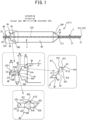
- the balloon catheter 1A will now be described with reference to Fig. 1 to Fig. 2 .
- the balloon catheter 1A has a catheter shaft 2, the balloon 3, and protruding portions 4A and 4B.
- the catheter shaft 2 has a tubular shape.
- the balloon 3 is connected near an end portion on one side of the catheter shaft 2.
- a hub is connected to an end portion on the other side of the catheter shaft 2. The hub can supply compressed fluid to the balloon 3 via the catheter shaft 2.
- the one side from among both ends of the catheter shaft 2 will be referred to as a distal end side.
- the other side from among both ends of the catheter shaft 2 will be referred to as a proximal end side.
- the direction extending along the catheter shaft 2 will be referred to as an extending direction.
- An axis passing through the center of the catheter shaft 2 and extending in the extending direction will be referred to as a center axis C1.
- the side near the center axis C1 in a radial direction centered on the center axis C1 will be referred to as the an inner side
- the side away from the center axis C1 will be referred to as an outer side.
- the catheter shaft 2 has an outer tube 21 and an inner tube 22.
- the outer tube 21 and the inner tube 22 are both flexible.
- the inside diameter of the outer tube 21 is larger than the outside diameter of the inner tube 22.
- the inner tube 22 is disposed inside the lumen of the outer tube 21.
- the predetermined portion on the distal end side of the inner tube 22 protrudes toward the distal end side from an end (hereinafter referred to as a distal end portion 211) on the distal end side of the outer tube 21.
- the end (hereinafter referred to as a distal end portion 221) on the distal end side of the inner tube 22 is disposed farther toward the distal end side than the distal end portion 211 of the outer tube 21.
- the predetermined portion on the distal end side of the inner tube 22 will be referred to as a protruding portion 225.
- the end on the proximal end side of the outer tube 21 will be referred to as a proximal end portion 212.
- the end on the proximal end side of the inner tube 22 will be referred to as a proximal end portion 222.
- the hub is connected to at least the proximal end portion 212 of the outer tube 21.
- the material of the outer tube 21 and the inner tube 22 is not particularly limited; a polyamide resin may be used as an example.
- the compressed fluid supplied from the hub flows through a space of the lumen of the outer tube 21 other than the lumen of the inner tube 22.
- a guide wire that is not shown in the drawings is inserted through the lumen of the inner tube 22.
- the balloon 3 can change shape between a deflated state and an inflated state, as a result of a change in internal pressure according to whether the compressed fluid is supplied from the hub not shown in the drawings.
- Fig. 1 shows the balloon 3 in the inflated state.
- An end (hereinafter referred to as a distal end portion 3D) on the distal end side of the balloon 3 is connected by thermal welding to a portion farther toward the proximal end side than the distal end portion 221 of the protruding portion 225 of the inner tube 22.
- the portion of the protruding portion 225 of the inner tube 22 that is between the portion where the distal end portion 3D of the balloon 3 is connected and the distal end portion 221 will be referred to as a distal end extending portion 220.
- the end portion (hereinafter, referred to as a proximal end portion 3P) on the proximal end side of the balloon 3 is connected by thermal welding to near the distal end portion 211 of the outer tube 21.
- the distance between the distal end portion 3D of the balloon 3 and the distal end portion 221 of the inner tube 22 is shorter than the distance between the proximal end portion 3P of the balloon 3 and the proximal end portion 222 of the inner tube 22.
- the balloon 3 covers the protruding portion 225 of the inner tube 22 from the outside.
- the material of the balloon 3 is not particularly limited; a polyamide resin may be used as an example.
- a distal end connecting portion 3A, an inflatable portion 3B, and a proximal end connecting portion 3C are defined in the balloon 3.
- the distal end connecting portion 3A is a region extending from the distal end portion 3D toward the proximal end portion 3P of the balloon 3 in the inflated state while increasing in diameter.
- the proximal end connecting portion 3C is a region extending from the proximal end portion 3P toward the distal end portion 3D of the balloon 3 in the inflated state while increasing in diameter.
- the inflatable portion 3B is a region sandwiched between the distal end connecting portion 3A and the proximal end connecting portion 3C of the balloon 3 in the inflated state, which has substantially the same diameter in the extending direction.
- the inflatable portion 3B has a tubular shape that extends in the extending direction in the inflated state.
- the side nearer to the distal end portion 221 of the inner tube 22 of the catheter shaft 2, i.e., the end portion on the distal end side, of the inflatable portion 3B will be referred to as a distal end portion 30D.
- the side nearer to the proximal end portion 222 of the inner tube 22 of the catheter shaft 2, i.e., the end portion on the proximal end side, of the inflatable portion 3B will be referred to as a proximal end portion 30P.
- the distal end connecting portion 3A extends to the distal end side from the end portion that connects with the distal end portion 30D of the inflatable portion 3B toward the distal end portion 3D.
- the diameter of a cross-section of the distal end connecting portion 3A is largest at the end portion that is connected to the distal end portion 30D of the inflatable portion 3B, and smallest at the distal end portion 3D.
- the proximal end connecting portion 3C extends to the proximal end side from the end portion that is connected to the proximal end portion 30P of the inflatable portion 3B toward the proximal end portion 3P.
- the diameter of a cross-section of the proximal end connecting portion 3C is largest at the end portion that is connected to the proximal end portion 30P of the inflatable portion 3B, and smallest at the proximal end portion 3P.
- the protruding portion 4A is provided on the outer surface of the distal end connecting portion 3A of the balloon 3 and protrudes outward.
- the protruding portion 4A has protrusions 41A and 42A.
- the protrusions 41A and 42A face one another across the center axis C1.
- the protrusions 41A and 42A each have a conical shape.
- the bottom portions of the protrusions 41A and 42A are connected to the outer surface of the distal end connecting portion 3A of the balloon 3.
- the protrusions 41A and 41B have the same shape.
- the shortest distance between the bottom surfaces of the 41A and 41B and the apex 410 corresponds to the protrusion amount of the protruding portion 4A.
- the shape of the protruding portion 4A will be described using the protrusion 41A as an example.
- the portion of the bottom portion of the protrusion 41A that is nearest to the distal end portion 3D of the distal end connecting portion 3A will be referred to as a distal end portion 415.
- the portion of the side surface of the protrusion 41A that corresponds to a generating line that connects the apex 410 to the distal end portion 415 will be referred to as a distal end inclined portion 411.
- the distal end inclined portion 411 extends along the side surface of the protrusion 41A from the distal end portion 415 toward the apex 410.
- the portion of the bottom portion of the protrusion 41A that is nearest to the distal end portion 30D of the inflatable portion 3B will be referred to as a proximal end portion 416.
- the proximal end portions 416 of the protrusions 41A and 42A are spaced apart from the distal end portion 30D of the inflatable portion 3B of the balloon 3 toward the distal end side. Therefore, the distal end connecting portion 3A of the balloon 3 includes a region W1 where the protruding portion 4A is not provided, between the proximal end portion 416 of the protruding portion 4A and the portion where the distal end portion 30D of the inflatable portion 3B connects in the extending direction.
- the distal end portion 415 of each of the protrusions 41A and 42A is spaced apart from the distal end portion 3D of the distal end connecting portion 3A of the balloon 3 toward the proximal end side.
- the distal end connecting portion 3A of the balloon 3 includes a region W2 where the protruding portion 4Ais not provided, between the distal end portion 415 of the protruding portion 4A and the distal end portion 3D in the extending direction.
- the protruding portion 4B is provided on the outer surface of the distal end extending portion 220 of the inner tube 22 and protrudes outward.
- the protruding portion 4B has protrusions 41B and 42B.
- the protrusions 41B and 42B face one another across the center axis C1.
- the protrusions 41B and 42B each have a conical shape.
- An apex 420 of each protrusion 41B and 42B protrudes farthest outward of the protrusions 41B and 42B.
- the bottom portions of the protrusions 41B and 42B are connected to the outer surface of the distal end extending portion 220.
- the protrusions 41B and 42B have the same shape.
- the protrusion amount of the protruding portion 4B is smaller than the protrusion amount of the protruding portion 4A.
- the shape of the protruding portion 4B will be described using the protrusion 41B as an example.
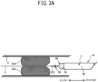
- the balloon catheter 1A is used to dilate a stenotic lesion 90A that has occurred at a portion of the interior wall of a blood vessel 9 will be illustrated.
- the lumen of the stenotic lesion 90A is extremely small, and the diameter of the lumen is smaller than the diameter of the balloon 3 in the deflated state.
- a guide wire G is inserted through the blood vessel 9.
- the balloon catheter 1A is prepared with the balloon 3 in the deflated state. As shown in Fig. 3A , a portion of the balloon catheter 1A that includes at least the balloon 3 is placed within the blood vessel 9.
- the guide wire G is inserted through the inner tube 22 of the balloon catheter 1A.
- the balloon catheter 1A is pushed into the blood vessel 9 along the guide wire G by operating the proximal end of the balloon catheter 1A.
- the balloon catheter 1A moves distally inside the blood vessel 9 toward the stenotic lesion 90A with the balloon 3 placed at the front in the moving direction.
- the distal end connecting portion 3A of the balloon 3 reaches the area near the proximal end portion of the stenotic lesion 90A.
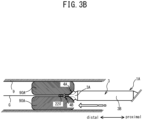
- Fig. 3B only a portion on the distal end side of the distal end connecting portion 3A enters the proximal end portion of the lumen of the stenotic lesion 90A. Then, movement of the balloon catheter 1A toward the distal side is stopped.
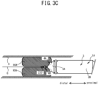
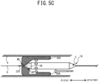
- the compressed fluid starts to be supplied to the balloon 3 so that the balloon 3 comes to be in the inflated state, as shown in Fig. 3C .
- the protruding portion 4A provided on the distal end connecting portion 3A digs into the interior wall of the stenotic lesion 90A.
- the balloon 3 dilates the area near the proximal end portion of the lumen of the stenotic lesion 90A with the distal end connecting portion 3A. Note that because the distal end connecting portion 3A increases in diameter toward the proximal side, a force in the proximal direction acts on the balloon 3 from the stenotic lesion 90A as the balloon 3 changes to the inflated state.
- the protruding portion 4A digs into the stenotic lesion 90A, movement of the balloon 3 toward the proximal side is suppressed. Furthermore, the balloon 3 is inhibited from being pushed back toward the proximal side because the protruding portion 4B catches on the lumen of the stenotic lesion 90A.
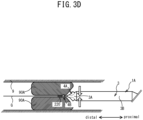
- the supplied compressed fluid is removed so that the balloon 3 comes to be in the deflated state, as shown in Fig. 3D .
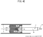
- the balloon catheter 1A moves distally by the proximal end being operated as shown in Fig. 3E .
- the distal end connecting portion 3A of the balloon 3 enters deeper into the lumen from the dilated proximal end portion of the stenotic lesion 90A. Then, movement of the balloon catheter 1A is stopped.
- protruding portion 4A digs into the stenotic lesion 90A and the protruding portion 4B catches on the lumen of the stenotic lesion 90A. Therefore, movement of the balloon 3 toward the proximal side is inhibited even if force toward the proximal side acts on the balloon 3 in response to the balloon 3 changing to the inflated state.
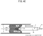
- the supplied compressed fluid is removed from the balloon 3 so that the balloon 3 comes to be in the deflated state, as shown in Fig. 4B .
- the balloon catheter 1A can dilate the stenotic lesion 90A having a small lumen by gradually advancing the balloon 3 distally while repeatedly changing the balloon 3 between the inflated state and the deflated state.
- the balloon catheter 1A is provided with the protruding portion 4A on the distal end connecting portion 3A of the balloon 3, and the protruding portion 4B on the distal end extending portion 220 of the inner tube 22.
- the protruding portions 4A and 4B inhibit the balloon 3 from moving proximally even if force toward the proximal side is received from the stenotic lesion 90A when the balloon 3 inflates. Therefore, the balloon catheter 1A can suitably dilate even the stenotic lesion 90A having a small lumen by performing an operation that gradually moves the balloon 3 distally while repeatedly changing the balloon 3 between the inflated state and the deflated state.
- the distal end connecting portion 3A of the balloon 3 includes the regions W1 and W2 where the protruding portion 4A is not provided. Therefore, the size of the region of the distal end connecting portion 3A where the protruding portion 4A is provided is smaller than it is when the protruding portion 4Ais provided across the entire region in the extending direction of the distal end connecting portion 3A. Also, the distal end extending portion 220 of the inner tube 22 includes the regions W3 and W4 where the protruding portion 4B is not provided.
- the size of the region of the distal end extending portion 220 where the protruding portion 4B is provided is smaller than it is when the protruding portion 4B is provided across the entire region in the extending direction of the distal end extending portion 220. Therefore, the balloon catheter 1A makes it possible to achieve excellent passablity of the balloon 3 through the blood vessel 9 compared to when the protruding portions 4A and 4B are provided along the entire region of the distal end connecting portion 3A and the distal end extending portion 220.
- the balloon catheter 1A enables the protruding portion 4A provided on the distal end connecting portion 3A of the balloon 3 to dig into the stenotic lesion 90A in the process of repeatedly inflating and deflating the balloon 3 to dilate the stenotic lesion 90A in the blood vessel 9.
- the balloon 3 can be inhibited from moving backward proximally even if the balloon 3 receives proximal force from the stenotic lesion 90A when the balloon 3 is inflating. Therefore, because the balloon catheter 1A can inflate the balloon 3 while gradually advancing the balloon 3 with respect to the stenotic lesion 90A having a small lumen, the balloon catheter 1Ais able to efficiently dilate the stenotic lesion 90A having a small lumen.
- the angle ⁇ 12 of the proximal end inclined portion 412 with respect to the distal end connecting portion 3A is greater than the angle ⁇ 11 of the distal end inclined portion 411 with respect to the distal end connecting portion 3A.
- the resistance force that the protruding portion 4A receives from the stenotic lesion 90A when the balloon 3 enters the lumen of the stenotic lesion 90A can be suppressed. Therefore, the balloon catheter 1A can reduce the possibility of the balloon 3 being pushed back proximally by the resistance force from the stenotic lesion 90A during the process of the balloon 3 entering the stenotic lesion 90A.
- the angle ⁇ 22 of the proximal end inclined portion 422 with respect to the distal end extending portion 220 is greater than the angle ⁇ 21 of the distal end inclined portion 421 with respect to the distal end extending portion 220.
- the balloon catheter 1A can reduce the possibility of the protruding portion 4B catching on the blood vessel 9 and thus being impeded from advancing when the balloon 3 is advanced inside the blood vessel 9.
- the shape, number, and arrangement of the protrusions of the protruding portions 4A and 4B are not limited to those in the foregoing embodiment.
- the number of protrusions of the protruding portions 4A and 4B may be one or three or more.
- the three or more protrusions may be arranged in the circumferential direction around the center axis C1.
- the shape of the protrusions of the protruding portions 4A and 4B may be a pyramid, a truncated cone, a truncated pyramid, etc., or a prism.
- one of the side surfaces may connect to the distal end connecting portion 3A of the balloon 3, and the remaining two side surfaces may form the distal end inclined portion 411 and the proximal end inclined portion 412, and the intersection of the remaining two side surfaces may form the apex 410.
- the angle ⁇ 21 of the distal end inclined portion 421 with respect to the distal end extending portion 220 and the angle ⁇ 22 of the proximal end inclined portion 422 with respect to the distal end extending portion 220 may be the same, or the angle ⁇ 21 may be greater than the angle ⁇ 22.
- One of the angle ⁇ 21 or the angle ⁇ 22 may be orthogonal to the distal end extending portion 220.
- the ratio of the protrusion amount of the first protruding portion to the protrusion amount of the protruding portion 4A, and the ratio of the protrusion amount of the second protruding portion to the protrusion amount of the protruding portion 4B are not particularly limited, and may be, for example, 50% or less, and more preferably, 10% or less.
- the first protruding portion may be provided on the entire region between the distal end portion 3D and the portion of the distal end connecting portion 3A of the balloon 3 where the distal end portion 30D of the inflatable portion 3B is connected. Also, the protrusion amount of the first protruding portion may be less than the protrusion amount of the protruding portion 4B.
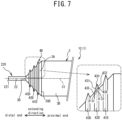
- the balloon catheter 1B will now be described with reference to Fig. 6 .
- the balloon catheter 1B differs from the balloon catheter 1A in that it does not have the protruding portion 4B, and has a protruding portion 4C instead of the protruding portion 4A.
- a description of the structure of the balloon catheter 1B that is the same as that of the balloon catheter 1A will be omitted.
- the protruding portion 4C has protrusions 41C and 42C that have the same shape as the protrusions 41A and 41B of the protruding portion 4A.
- the protrusions 41C and 42C are provided on a portion of the outer surface of the distal end connecting portion 3A of the balloon 3 that includes the distal end portion 3D.
- a portion on the distal end side of each of the protrusions 41C and 42C is provided on the outer surface of the distal end extending portion 220 of the inner tube 22, and a portion on the proximal end side of each of the protrusions 41C and 42C is provided on the outer surface of the distal end connecting portion 3A of the balloon 3.
- the end portion of the distal end inclined portion 431 on the side opposite the distal end portion 435 and the end portion of the proximal end inclined portion 432 on the side opposite the proximal end portion 436 are connected at an apex 430.
- the angle ⁇ 32 of the proximal end inclined portion 432 with respect to the distal end connecting portion 3A is greater than the angle ⁇ 31 of the distal end inclined portion 431 with respect to the distal end connecting portion 3A.
- the number and shape of the protrusions of the protruding portion 4D are not limited to those of the foregoing embodiment.
- the apex 430 of each of the protrusions 41D to 43D may be curved outward in a protruding shape.
- An annular protruding portion extending in the circumferential direction around the center axis C1 may also be provided on the distal end extending portion 220 of the inner tube 22.
- the connecting portion that connects the protrusions 41D to 43D may extend in the extending direction along the outer surface of the distal end connecting portion 3A.
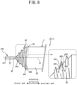
- the portion near the distal end portion 3D of the distal end connecting portion 3A, of the portion of the protruding portion 4E that is connected to the distal end connecting portion 3A will be referred to as a distal end portion 445.
- the planar-shaped portion extending inclined with respect to the radial direction from the distal end portion 445 toward the proximal end side will be referred to as a distal end inclined portion 441.
- the portion near the distal end portion 30D of the inflatable portion 3B, of the portion of the protruding portion 4E that is connected to the distal end connecting portion 3A will be referred to as a proximal end portion 446.
- the planar-shaped portion extending inclined with respect to the radial direction from the proximal end portion 446 toward the distal end side will be referred to as a proximal end inclined portion 442.
- the end portion of the distal end inclined portion 441 on the side opposite the distal end portion 445 and the end portion of the proximal end inclined portion 442 on the side opposite the proximal end portion 446 are connected at an apex 440.
- the angle ⁇ 42 of the proximal end inclined portion 442 with respect to the distal end connecting portion 3A is greater than the angle ⁇ 41 of the distal end inclined portion 441 with respect to the distal end connecting portion 3A.
- the balloon catheter 1D can apply the protruding portion 4E to the stenotic lesion 90A over a wide area in the extending direction and the circumferential direction of the distal end connecting portion 3A. Therefore, with the balloon catheter 1D, the protruding portion 4E can inhibit the balloon 3 from moving in the direction opposite the direction of entry into the stenotic lesion 90A when the balloon 3 inflates.
- the shape of the protruding portion 4E is not limited to that of the foregoing embodiment.
- the apex 440 of the protruding portion 4E may be curved outward in a protruding shape.
- a spiral-shaped protruding portion that extends in the circumferential direction around the center axis C1 may also be provided on the distal end extending portion 220 of the inner tube 22.
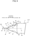
- the balloon catheter 1E will now be described with reference to Fig. 9 .
- the balloon catheter 1E differs from the balloon catheter 1A in that the protruding portion 4B is not provided on the distal end extending portion 220. Also, the shape of the distal end connecting portion 3A of the balloon 3 differs from that of the balloon catheter 1A.
- a description of the structure of the balloon catheter 1E that is the same as that of the balloon catheter 1A will be omitted.
- the distal end connecting portion 3A of the balloon 3 has inclined portions 36, 37, and 38.
- the inclined portion 36 extends while increasing in diameter from the distal end portion 3D of the distal end connecting portion 3A toward the proximal end side.
- the inclined portion 37 extends while increasing in diameter from the end portion of the inclined portion 36 on the side opposite the end portion of the inclined portion 36 that is connected to the distal end portion 3D in the extending direction toward the proximal end side.
- the inclined portion 38 extends while increasing in diameter from the end portion of the inclined portion 37 on the side opposite the end portion of the inclined portion 37 that is connected to the inclined portion 36 in the extending direction toward the proximal end side.
- the angles formed between the extending direction and the direction extending from the end portion near the distal end portion 3D toward the end portion near the distal end portion 30D are defined as the inclination angles.
- the inclination angle of the inclined portion 36 is denoted ⁇ 51
- the inclination angle of the inclined portion 37 is denoted ⁇ 52
- the inclination angle of the inclined portion 38 is denoted ⁇ 53.
- the inclination angles ⁇ 51, ⁇ 52, and ⁇ 53 are different from each other.
- the inclination angles ⁇ 51 to ⁇ 53 have a magnitude relationship of ⁇ 52 ⁇ ⁇ 51 ⁇ ⁇ 53.
- the inclination angle ⁇ 53 is the largest and the inclination angle ⁇ 52 is the smallest.
- the shape of the protrusions 41A and 42A of the protruding portion 4A is the same as it is in the balloon catheter 1A.
- the protrusions 41A and 42A are provided on the inclined portion 37 which has the smallest inclination angle ⁇ 52 of the inclined portions 36 to 38.
- the protruding portion 4A is provided on the inclined portion 37 having the relatively small inclination angle ⁇ 52.
- the protruding portion 4A moves in a direction orthogonal to the inclined portion 37.
- the inclination angle ⁇ 52 is defined as the angle of the inclined portion 37 with respect to the extending direction, so when the inclination angle ⁇ 52 is small, the angle between the direction orthogonal to the inclined portion 37, i.e., the moving direction of the protruding portion 4A when the balloon 3 inflates, and the radial direction orthogonal to the extending direction is also small.
- the protruding portion 4A moves in a direction approximating the radial direction when the balloon 3 inflates. Therefore, the balloon catheter 1E enables the protruding portion 4Ato suitably dig into the stenotic lesion 90A when the balloon 3 inflates.
- the shape of the protruding portion 4A provided on the inclined portion 37 is not limited to that of the foregoing embodiment.
- the protruding portion may have the shape (annular shape) of the protruding portion 4D in the third embodiment, or the shape (spiral shape) of the protruding portion 4E in the fourth embodiment.
- the inclination angles ⁇ 51 and ⁇ 53 may be the same.
- the number of inclined portions of the distal end connecting portion 3A is not limited to three, and may be two or four or more. If there are three or more inclined portions, protruding portions may be provided on a plurality of the inclined portions having an inclination angle less than a predetermined threshold value.
- the protruding portion 4A may protrude outward with respect to the virtual plane S0.
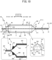
- the balloon catheter 1F will now be described with reference to Fig. 10 .
- the balloon catheter 1F differs from the balloon catheter 1A in that it has protruding portions 4G and 4H in addition to the protruding portion 4A, but does not have the protruding portion 4B.
- a description of the structure of the balloon catheter 1F that is the same as that of the balloon catheter 1A will be omitted.
- the protruding portion 4G is provided on the outer surface of the inflatable portion 3B of the balloon 3 and protrudes outward.
- the protruding portion 4G has protrusions 41G and 42G.
- the protrusions 41G and 42G both extend in the extending direction between the proximal end portion 30P and the distal end portion 30D of the inflatable portion 3B.
- the protrusions 41G and 42G face each other across the center axis C1.
- the positions of the protrusions 41A and 41G in the circumferential direction coincide.
- the positions of the protrusions 42A and 42G in the circumferential direction coincide.
- the shape of the protrusions 41G and 42G is the same. Hereinafter, the shape will be described giving the protrusion 41G as an example.
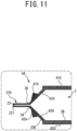
- the protrusion 41G has a base portion 51 and a tip end portion 52.
- the shape of the base portion 51 is a quadratic prism, extending in the extending direction.
- a side surface 51A of the base portion 51 is connected to the outer surface of the inflatable portion 3B of the balloon 3.
- the shape of the tip end portion 52 is a triangular prism, extending in the extending direction.
- a side surface 52A of the tip end portion 52 is connected to a side surface 51B of the base portion 51 that is opposite to the side surface 51A.
- Side surfaces 52B and 52C of the tip end portion 52 other than the side surface 52A are connected to an apex 520.
- the distance between the side surfaces 51A and 52B of the base portion 51, and the distance between the apex 520 and the side surface 52A of the tip end portion 52 are equal.
- both end portions 510 of the side surface 51A in a direction orthogonal to the extending direction are defined.
- two virtual line segments S1 connecting each of the end portions 510 and the apex 520 are defined.
- a portion of each of the tip end portion 52 and the base portion 51 of the protrusion 41G is arranged to the outside of a virtual triangle (hereinafter, referred to as a virtual triangle T1) defined by the two virtual line segments S1 and the side surface 51A.
- the protruding portion 4H is provided on an inner surface of the distal end connecting portion 3A of the balloon 3 and protrudes inward.
- the protruding portion 4H has protrusions 41H and 42H.
- the protruding portion 41H extends between the protrusion 41A and the end portion on the distal end side of the protrusion 41G.
- the protrusion 42H extends between the protrusion 42A and the end portion on the distal end side of the protrusion 42G.
- the protruding portion 4H is interposed between the protruding portions 4A and 4G and connects the protruding portions 4A and 4G inside the balloon 3.
- the rigidity of the portion where the protruding portion 4H is provided on the balloon 3 can be equal to the rigidity of the portion of the balloon 3 where the protruding portion 4Ais provided. Therefore, the protruding portion 4H can inhibit the balloon 3 from being pushed back in the direction toward the center axis C1 due to the protruding portion 4A receiving force from the stenotic lesion 90A when the balloon 3 inflates.
- the protruding portion 4H protrudes inward from the inner surface of the distal end connecting portion 3A of the balloon 3, and does not protrude outward from the outer surface of the distal end connecting portion 3A of the balloon 3. Therefore, the balloon catheter 1F can inhibit a decrease in passability of the balloon 3 due to the provision of the protruding portion 4H.
- the protruding portion 4H can suitably form wings in the balloon 3 in the deflated state, so the diameter of the balloon 3 in the deflated state can be reduced.
- a third protruding portion that protrudes outward may be provided on the outer surface of the portion of the distal end connecting portion 3A of the balloon 3 where the protruding portion 4H is provided on the inner surface.
- the protrusion amount of the third protruding portion may be smaller than the protrusion amount of the protruding portion 4A.
- the ratio of the protrusion amount of the third protruding portion to the protrusion amount of the protruding portion 4A is not particularly limited, and is, for example, 50% or less, and more preferably, 10% or less.
- the protruding portion 4H may further extend between the end portion on the distal end side of the protruding portion 4G and the distal end portion 3D of the balloon 3.
- the protruding portion 4H may be provided between the distal end portion 3D of the balloon 3 and the end portion on the distal end side of the protruding portion 4G on the inner surface of the distal end connecting portion 3A of the balloon 3.
- the protruding portion 4G may be provided on the inner surface of the inflatable portion 3B of the balloon 3 and protrude inward.
- the protruding portion 4G may be formed in an annular shape in the circumferential direction around the center axis C1. In this case, the protruding portion 4G may be formed only near the distal end portion 30D of the inflatable portion 3B of the balloon 3.
- the protruding portion 4H may be provided on the entire region on the proximal end side of the protruding portion 4A in the extending direction, of the inner surface of the distal end connecting portion 3A of the balloon 3.
- the hardness of each of the protrusions 41G and 42G of the protruding portion 4G may the uniform across the entire region or different for each portion. For example, as shown in Fig. 12A , the hardness of each of the protrusions 41G and 42G may become gradually harder from the side surface 51A toward the apex 520. In this case, the area of the protrusions 41G and 42G near the apex 520, in particular, will not easily fall down even if external force is applied, so the protruding portion 4G is able to appropriately dig into the stenotic lesion 90A when the balloon 3 inflates. Also, the area near the portion of the protrusions 41G and 42G that is connected to the balloon 3 can remain flexible. Therefore, it is possible to suppress a decrease in passability due to the protruding portion 4G catching on the interior wall when the balloon 3 passes through the blood vessel 9.
- a virtual center S2 that is a virtual line segment that passes through the apex 520 and extends in the radial direction is defined for the protrusions 41G and 42G.
- Side surfaces 51C and 51D excluding the side surfaces 51A and 51B are defined for each base portion 51 of the protrusions 41G and 42G.
- the hardness of each of the protrusions 41G and 42G may become gradually harder from each of the side surfaces 51C, 51D, 52B, and 51C toward the virtual center S2.
- the hardness of the portion located inside the virtual triangle T1 may be higher than the hardness of the portion located outside the virtual triangle T1.
- the protruding portion 4G is stably arranged on the outer surface of the balloon 3, and so will not easily fall down even if external force is applied. Therefore, the protruding portion 4G is able to suitably dig into the stenotic lesion 90A when the balloon 3 inflates.
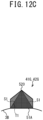
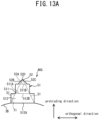
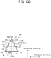
- the shape of the protruding portion 4G is not limited to that of the foregoing embodiment. Modified examples (protrusions 46G (refer to Fig. 13A ), 47G (refer to Fig. 13B ), and 48G (refer to Fig. 13C )) relating to the shape of the protrusions 41G and 42G of the protruding portion 4G will now be described.
- the direction passing through the apex 520 from the center axis C1 of the balloon 3 and extending in the radial direction will be referred to as the a protruding direction.
- the direction orthogonal to the extending direction and orthogonal to the protruding direction will be referred to as an orthogonal direction.
- the length of the base element 511 in the orthogonal direction is shorter than the length of the base element 512 in the orthogonal direction.
- the length of the side surface 52A of the tip end portion 52 is shorter than the length of the base element 511 in the orthogonal direction.
- a portion including both orthogonal end portions of the base elements 511 and 512 and the tip end portion 52 is arranged outside of the virtual triangle T1.
- the length of the base portion 51 in the protruding direction is longer than the length of the tip end portion 52 in the protruding direction.
- the protrusion 46G can stably support the tip end portion 52 by the base portion 51. Therefore, the protrusion 46G allows the tip end portion 52 of the protrusion 46G to suitably dig into the stenotic lesion 90A when the balloon 3 inflates.
- the protrusion 47G shown in Fig. 13B differs from the protrusion 46G (refer to Fig. 13A ) in terms of the shape of the base element 512.
- the shape of the base element 512 is a prism with a trapezoidal cross-section.
- the side surface 512B of the base element 512 is shorter than the side surface 512A of the base element 512. Note that the side surface 512B is longer than the side surface 511A of the base element 511.
- side surfaces 512C and 512D excluding the side surfaces 512A and 512B, are defined.
- the direction extending from the side surface 512A side to the side surface 512B side along the side surfaces 512C and 512D is inclined toward the virtual center S2 that passes through the apex 520.
- portions including both end portions in the orthogonal direction of the tip end portion 52 and the base elements 511 and 512 are arranged outside of the virtual triangle T1.
- side surfaces 511C and 511D excluding the side surfaces 511A and 511B, are defined.
- the direction extending from the side surface 511A side to the side surface 511B side along the side surfaces 511C and 511D is inclined toward the virtual center S2 that passes through the apex 520.
- portions including both end portions in the orthogonal direction of the tip end portion 52 and the base elements 511 and 512 are arranged outside of the virtual triangle T1.
- the tip end portion 52 can be more stably supported by the base portion 51. Therefore, the protrusions 47G and 48G can appropriately apply each of the tip end portions 52 to the stenotic lesion 90A when the balloon 3 inflates. Also, with the protrusions 47G and 48G, the step of the side surface in the orthogonal direction can be smaller, so the protrusions 47G and 48G will not easily fall over even if the protrusion amount of the protrusions 47G and 48G is large. Consequently, by making the protrusion amount of the protrusions 47G and 48G large, the protrusions 47G and 48G can appropriately dig into the stenotic lesion 90A when the balloon 3 inflates.
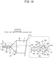
- the protruding portion 4I has protrusions 41I, 42I, 43I, 44I, 45I, and 46I.
- the protrusions 41I to 46I are provided on the outer surface of the distal end extending portion 220 of the inner tube 22 and protrude outward.
- the protrusions 41I, 42I, and 43I are arranged along the extending direction.
- the positions of the 41I, 42I, and 43I in the circumferential direction coincide.
- the protrusions 44I, 45I, and 46I are arranged along the extending direction.
- the positions of the protrusions 44I, 45I, and 46I in the circumferential direction coincide.
- the protrusions 41I, and 44I are near the distal end portion 30D of the balloon 3.
- the protrusions 43I and 46I are near the distal end portion 221 of the inner tube 22.
- the protrusions 41I and 44I face each other across the center axis C1.
- the protrusions 42I and 45I face each other across the center axis C1.
- the protrusions 41I and 44I face each other across the center axis C1.
- the balloon catheter 1G has the protrusions 411 to 43I and 44I to 46I arranged in the extending direction. Therefore, compared to the balloon catheter 1A having only the protrusions 41A and 41B, the balloon 3 is less likely to be pushed back when the distal end extending portion 220 of the inner tube 22 receives resistance force from the stenotic lesion 90A as it advances through the lumen of the stenotic lesion 90A. Therefore, the balloon catheter 1G can more efficiently perform the operation of gradually advancing the balloon 3 distally while repeatedly changing the balloon 3 between the inflated state and the deflated state.
- the cover tube 7A is provided in a position overlapping with the region W7.
- the hardness of the region W7 is harder than the hardness of the region W6, and the hardness of the region W8 is harder than the hardness of the region W7 (hardness of the region W6 ⁇ hardness of the region W7 ⁇ the hardness of region W8).
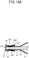
- Cover tubes 7B ( Figs. 16A ), 7C ( Fig. 16B ), and 7D ( Fig. 16C ) that are modified examples of the cover tube 7A will now be described.
- the cover tube 7D shown in Fig. 16C differs from the cover tube 7A in that the hardness is not uniform.
- the hardness of the cover tube 7D is harder at a portion corresponding to the region W7 than at portions corresponding to the regions W6 and W8. Therefore, the difference in hardness between the regions W6 to W8 of the balloon catheter 1H can be reduced even more, so the trackability to the guide wire at the distal end portion can be improved even more.
- the regions W6 to W8 having different hardnesses may be formed by different materials.
- the hardness may be adjusted by varying the physical properties of the portions of the cover tube 7D, which is made of a common material, corresponding to each of the regions W6 to W8.
Landscapes
- Health & Medical Sciences (AREA)
- Life Sciences & Earth Sciences (AREA)
- Heart & Thoracic Surgery (AREA)
- Animal Behavior & Ethology (AREA)
- Veterinary Medicine (AREA)
- Public Health (AREA)
- Engineering & Computer Science (AREA)
- General Health & Medical Sciences (AREA)
- Biomedical Technology (AREA)
- Pulmonology (AREA)
- Hematology (AREA)
- Anesthesiology (AREA)
- Biophysics (AREA)
- Child & Adolescent Psychology (AREA)
- Surgery (AREA)
- Vascular Medicine (AREA)
- Orthopedic Medicine & Surgery (AREA)
- Nuclear Medicine, Radiotherapy & Molecular Imaging (AREA)
- Medical Informatics (AREA)
- Molecular Biology (AREA)
- Media Introduction/Drainage Providing Device (AREA)
Applications Claiming Priority (2)
| Application Number | Priority Date | Filing Date | Title |
|---|---|---|---|
| JP2021140754 | 2021-08-31 | ||
| PCT/JP2022/028567 WO2023032522A1 (ja) | 2021-08-31 | 2022-07-25 | バルーンカテーテル |
Publications (2)
| Publication Number | Publication Date |
|---|---|
| EP4397348A1 true EP4397348A1 (de) | 2024-07-10 |
| EP4397348A4 EP4397348A4 (de) | 2025-08-13 |
Family
ID=85412155
Family Applications (1)
| Application Number | Title | Priority Date | Filing Date |
|---|---|---|---|
| EP22864110.6A Pending EP4397348A4 (de) | 2021-08-31 | 2022-07-25 | Ballonkatheter |
Country Status (8)
| Country | Link |
|---|---|
| US (1) | US20240181226A1 (de) |
| EP (1) | EP4397348A4 (de) |
| JP (1) | JP7610016B2 (de) |
| KR (1) | KR20240037301A (de) |
| CN (1) | CN116981494A (de) |
| AU (1) | AU2022338382B2 (de) |
| CA (1) | CA3228244A1 (de) |
| WO (1) | WO2023032522A1 (de) |
Families Citing this family (1)
| Publication number | Priority date | Publication date | Assignee | Title |
|---|---|---|---|---|
| WO2025216010A1 (ja) * | 2024-04-11 | 2025-10-16 | 株式会社グッドマン | バルーンカテーテル |
Family Cites Families (20)
| Publication number | Priority date | Publication date | Assignee | Title |
|---|---|---|---|---|
| US5324260A (en) * | 1992-04-27 | 1994-06-28 | Minnesota Mining And Manufacturing Company | Retrograde coronary sinus catheter |
| US6027510A (en) * | 1997-12-08 | 2000-02-22 | Inflow Dynamics Inc. | Stent delivery system |
| DE60027787T2 (de) * | 1999-11-24 | 2007-04-12 | Pierce Chemical Co., Rockford | Granuliertes chromatographiematerial |
| US7306616B2 (en) * | 2003-05-05 | 2007-12-11 | Boston Scientific Scimed, Inc. | Balloon catheter and method of making same |
| US20060182873A1 (en) * | 2005-02-17 | 2006-08-17 | Klisch Leo M | Medical devices |
| US7857786B2 (en) * | 2006-11-03 | 2010-12-28 | Cook Incorporated | Balloon catheter having improved balloon folding capability |
| EP2566562A1 (de) * | 2010-05-07 | 2013-03-13 | Cook Medical Technologies LLC | Ballon mit integrierten segmentierten dilatationselementen |
| US9005163B2 (en) * | 2010-08-03 | 2015-04-14 | Bayer Pharma Aktiengesellschaft | Balloon catheter with external delivery tube |
| JP6442229B2 (ja) * | 2014-10-30 | 2018-12-19 | 株式会社グッドマン | バルーンカテーテル |
| WO2016163495A1 (ja) * | 2015-04-10 | 2016-10-13 | 株式会社グッドマン | バルーンカテーテル |
| EP3342446B1 (de) * | 2015-08-27 | 2023-01-18 | Goodman Co., Ltd. | Ballon für einen katheter, ballonkatheter und gussform |
| JP6581513B2 (ja) * | 2016-01-12 | 2019-09-25 | テルモ株式会社 | 医療用長尺体 |
| US10470905B2 (en) * | 2016-03-25 | 2019-11-12 | Ostial Corporation | Balloon catheters and methods for use |
| JP2020000677A (ja) * | 2018-06-29 | 2020-01-09 | 日本ゼオン株式会社 | 内視鏡用バルーンカテーテル |
| CN112203713B (zh) | 2018-07-09 | 2023-06-02 | 株式会社戈德曼 | 球囊导管 |
| KR102492421B1 (ko) * | 2018-07-09 | 2023-01-27 | 가부시키가이샤 굿맨 | 풍선카테터(Balloon catheter) |
| CN109363808B (zh) * | 2018-08-21 | 2020-09-08 | 陈绍良 | 一种扩张导管用球囊 |
| JP2020110419A (ja) * | 2019-01-15 | 2020-07-27 | テルモ株式会社 | バルーンカテーテル |
| CN210963508U (zh) * | 2019-07-04 | 2020-07-10 | 江西三鑫医疗科技股份有限公司 | 一种带螺纹筋的球囊扩张导管 |
| KR20230108282A (ko) * | 2020-11-16 | 2023-07-18 | 가부시키가이샤 가네카 | 벌룬 카테터용 벌룬 |
-
2022
- 2022-07-25 EP EP22864110.6A patent/EP4397348A4/de active Pending
- 2022-07-25 AU AU2022338382A patent/AU2022338382B2/en active Active
- 2022-07-25 JP JP2023545159A patent/JP7610016B2/ja active Active
- 2022-07-25 WO PCT/JP2022/028567 patent/WO2023032522A1/ja not_active Ceased
- 2022-07-25 KR KR1020247005686A patent/KR20240037301A/ko active Pending
- 2022-07-25 CA CA3228244A patent/CA3228244A1/en active Pending
- 2022-07-25 CN CN202280021617.4A patent/CN116981494A/zh active Pending
-
2024
- 2024-02-14 US US18/441,720 patent/US20240181226A1/en active Pending
Also Published As
| Publication number | Publication date |
|---|---|
| AU2022338382B2 (en) | 2025-10-16 |
| CA3228244A1 (en) | 2023-03-09 |
| JP7610016B2 (ja) | 2025-01-07 |
| EP4397348A4 (de) | 2025-08-13 |
| AU2022338382A1 (en) | 2024-03-14 |
| WO2023032522A1 (ja) | 2023-03-09 |
| KR20240037301A (ko) | 2024-03-21 |
| JPWO2023032522A1 (de) | 2023-03-09 |
| US20240181226A1 (en) | 2024-06-06 |
| CN116981494A (zh) | 2023-10-31 |
Similar Documents
| Publication | Publication Date | Title |
|---|---|---|
| US8348987B2 (en) | Balloon with scoring member | |
| US5002531A (en) | Dilation catheter with an inflatable balloon | |
| US4819751A (en) | Valvuloplasty catheter and method | |
| AU614976B2 (en) | Limacon geometry balloon angioplasty catheter systems and method of making same | |
| US20080200943A1 (en) | Expandable medical access sheath | |
| US20060030814A1 (en) | Method and apparatus for selective drug infusion via an intra-aortic flow diverter delivery catheter | |
| KR102491375B1 (ko) | 풍선 카테터(balloon catheter) | |
| EP2431068A1 (de) | Dilatationskatheter | |
| JPS62502950A (ja) | バルーン冠状血管脈管形成プローブ | |
| US20120116500A1 (en) | H-Side Branch Stent | |
| EP4397348A1 (de) | Ballonkatheter | |
| US20160000593A1 (en) | Delivery system for a living body indwelling member | |
| WO2000013736A1 (en) | Finned-tip flow guided catheters | |
| WO2023103542A1 (zh) | 延长导管 | |
| CN113924139A (zh) | 球囊导管 | |
| JP2018161415A (ja) | 医療用長尺体 | |
| EP3868432A1 (de) | Endovaskulärer katheter mit internem ballon | |
| JP7547634B2 (ja) | バルーンカテーテル | |
| CN215608673U (zh) | 一种前端配有微球囊的微导管 | |
| US20220346994A1 (en) | Vascular and aortic connectors with robotic delivery and deployment methods thereof | |
| JPH0311008Y2 (de) | ||
| CN120361398B (zh) | 一种外置灌注组件及灌注球囊导管 | |
| CN221242973U (zh) | 抽吸导管 | |
| CN114042227A (zh) | 可充卸压式刻痕丝球囊扩张导管 | |
| CN119867879B (zh) | 一种心脑血管护理用介入导管组件 |
Legal Events
| Date | Code | Title | Description |
|---|---|---|---|
| STAA | Information on the status of an ep patent application or granted ep patent |
Free format text: STATUS: THE INTERNATIONAL PUBLICATION HAS BEEN MADE |
|
| PUAI | Public reference made under article 153(3) epc to a published international application that has entered the european phase |
Free format text: ORIGINAL CODE: 0009012 |
|
| STAA | Information on the status of an ep patent application or granted ep patent |
Free format text: STATUS: REQUEST FOR EXAMINATION WAS MADE |
|
| 17P | Request for examination filed |
Effective date: 20240327 |
|
| AK | Designated contracting states |
Kind code of ref document: A1 Designated state(s): AL AT BE BG CH CY CZ DE DK EE ES FI FR GB GR HR HU IE IS IT LI LT LU LV MC MK MT NL NO PL PT RO RS SE SI SK SM TR |
|
| DAV | Request for validation of the european patent (deleted) | ||
| DAX | Request for extension of the european patent (deleted) | ||
| REG | Reference to a national code |
Ref country code: DE Ref legal event code: R079 Free format text: PREVIOUS MAIN CLASS: A61M0025000000 Ipc: A61M0025100000 |
|
| A4 | Supplementary search report drawn up and despatched |
Effective date: 20250710 |
|
| RIC1 | Information provided on ipc code assigned before grant |
Ipc: A61M 25/10 20130101AFI20250704BHEP Ipc: A61B 17/22 20060101ALI20250704BHEP |