EP4397347A2 - Filter - Google Patents
Filter Download PDFInfo
- Publication number
- EP4397347A2 EP4397347A2 EP24166370.7A EP24166370A EP4397347A2 EP 4397347 A2 EP4397347 A2 EP 4397347A2 EP 24166370 A EP24166370 A EP 24166370A EP 4397347 A2 EP4397347 A2 EP 4397347A2
- Authority
- EP
- European Patent Office
- Prior art keywords
- valve
- filter
- gases
- compartment
- configurations
- Prior art date
- Legal status (The legal status is an assumption and is not a legal conclusion. Google has not performed a legal analysis and makes no representation as to the accuracy of the status listed.)
- Granted
Links
Images






















Classifications
-
- A—HUMAN NECESSITIES
- A61—MEDICAL OR VETERINARY SCIENCE; HYGIENE
- A61M—DEVICES FOR INTRODUCING MEDIA INTO, OR ONTO, THE BODY; DEVICES FOR TRANSDUCING BODY MEDIA OR FOR TAKING MEDIA FROM THE BODY; DEVICES FOR PRODUCING OR ENDING SLEEP OR STUPOR
- A61M16/00—Devices for influencing the respiratory system of patients by gas treatment, e.g. ventilators; Tracheal tubes
- A61M16/10—Preparation of respiratory gases or vapours
- A61M16/105—Filters
-
- A—HUMAN NECESSITIES
- A61—MEDICAL OR VETERINARY SCIENCE; HYGIENE
- A61M—DEVICES FOR INTRODUCING MEDIA INTO, OR ONTO, THE BODY; DEVICES FOR TRANSDUCING BODY MEDIA OR FOR TAKING MEDIA FROM THE BODY; DEVICES FOR PRODUCING OR ENDING SLEEP OR STUPOR
- A61M16/00—Devices for influencing the respiratory system of patients by gas treatment, e.g. ventilators; Tracheal tubes
- A61M16/20—Valves specially adapted to medical respiratory devices
- A61M16/201—Controlled valves
-
- A—HUMAN NECESSITIES
- A61—MEDICAL OR VETERINARY SCIENCE; HYGIENE
- A61M—DEVICES FOR INTRODUCING MEDIA INTO, OR ONTO, THE BODY; DEVICES FOR TRANSDUCING BODY MEDIA OR FOR TAKING MEDIA FROM THE BODY; DEVICES FOR PRODUCING OR ENDING SLEEP OR STUPOR
- A61M16/00—Devices for influencing the respiratory system of patients by gas treatment, e.g. ventilators; Tracheal tubes
- A61M16/0057—Pumps therefor
- A61M16/0066—Blowers or centrifugal pumps
-
- A—HUMAN NECESSITIES
- A61—MEDICAL OR VETERINARY SCIENCE; HYGIENE
- A61M—DEVICES FOR INTRODUCING MEDIA INTO, OR ONTO, THE BODY; DEVICES FOR TRANSDUCING BODY MEDIA OR FOR TAKING MEDIA FROM THE BODY; DEVICES FOR PRODUCING OR ENDING SLEEP OR STUPOR
- A61M16/00—Devices for influencing the respiratory system of patients by gas treatment, e.g. ventilators; Tracheal tubes
- A61M16/08—Bellows; Connecting tubes ; Water traps; Patient circuits
- A61M16/0816—Joints or connectors
-
- A—HUMAN NECESSITIES
- A61—MEDICAL OR VETERINARY SCIENCE; HYGIENE
- A61M—DEVICES FOR INTRODUCING MEDIA INTO, OR ONTO, THE BODY; DEVICES FOR TRANSDUCING BODY MEDIA OR FOR TAKING MEDIA FROM THE BODY; DEVICES FOR PRODUCING OR ENDING SLEEP OR STUPOR
- A61M16/00—Devices for influencing the respiratory system of patients by gas treatment, e.g. ventilators; Tracheal tubes
- A61M16/10—Preparation of respiratory gases or vapours
- A61M16/12—Preparation of respiratory gases or vapours by mixing different gases
- A61M16/122—Preparation of respiratory gases or vapours by mixing different gases with dilution
- A61M16/125—Diluting primary gas with ambient air
-
- A—HUMAN NECESSITIES
- A61—MEDICAL OR VETERINARY SCIENCE; HYGIENE
- A61M—DEVICES FOR INTRODUCING MEDIA INTO, OR ONTO, THE BODY; DEVICES FOR TRANSDUCING BODY MEDIA OR FOR TAKING MEDIA FROM THE BODY; DEVICES FOR PRODUCING OR ENDING SLEEP OR STUPOR
- A61M16/00—Devices for influencing the respiratory system of patients by gas treatment, e.g. ventilators; Tracheal tubes
- A61M16/10—Preparation of respiratory gases or vapours
- A61M16/14—Preparation of respiratory gases or vapours by mixing different fluids, one of them being in a liquid phase
- A61M16/16—Devices to humidify the respiration air
- A61M16/161—Devices to humidify the respiration air with means for measuring the humidity
-
- A—HUMAN NECESSITIES
- A61—MEDICAL OR VETERINARY SCIENCE; HYGIENE
- A61M—DEVICES FOR INTRODUCING MEDIA INTO, OR ONTO, THE BODY; DEVICES FOR TRANSDUCING BODY MEDIA OR FOR TAKING MEDIA FROM THE BODY; DEVICES FOR PRODUCING OR ENDING SLEEP OR STUPOR
- A61M16/00—Devices for influencing the respiratory system of patients by gas treatment, e.g. ventilators; Tracheal tubes
- A61M16/10—Preparation of respiratory gases or vapours
- A61M16/14—Preparation of respiratory gases or vapours by mixing different fluids, one of them being in a liquid phase
- A61M16/18—Vaporising devices for anaesthetic preparations
-
- A—HUMAN NECESSITIES
- A61—MEDICAL OR VETERINARY SCIENCE; HYGIENE
- A61M—DEVICES FOR INTRODUCING MEDIA INTO, OR ONTO, THE BODY; DEVICES FOR TRANSDUCING BODY MEDIA OR FOR TAKING MEDIA FROM THE BODY; DEVICES FOR PRODUCING OR ENDING SLEEP OR STUPOR
- A61M16/00—Devices for influencing the respiratory system of patients by gas treatment, e.g. ventilators; Tracheal tubes
- A61M16/20—Valves specially adapted to medical respiratory devices
- A61M16/201—Controlled valves
- A61M16/202—Controlled valves electrically actuated
- A61M16/203—Proportional
-
- A—HUMAN NECESSITIES
- A61—MEDICAL OR VETERINARY SCIENCE; HYGIENE
- A61M—DEVICES FOR INTRODUCING MEDIA INTO, OR ONTO, THE BODY; DEVICES FOR TRANSDUCING BODY MEDIA OR FOR TAKING MEDIA FROM THE BODY; DEVICES FOR PRODUCING OR ENDING SLEEP OR STUPOR
- A61M11/00—Sprayers or atomisers specially adapted for therapeutic purposes
-
- A—HUMAN NECESSITIES
- A61—MEDICAL OR VETERINARY SCIENCE; HYGIENE
- A61M—DEVICES FOR INTRODUCING MEDIA INTO, OR ONTO, THE BODY; DEVICES FOR TRANSDUCING BODY MEDIA OR FOR TAKING MEDIA FROM THE BODY; DEVICES FOR PRODUCING OR ENDING SLEEP OR STUPOR
- A61M16/00—Devices for influencing the respiratory system of patients by gas treatment, e.g. ventilators; Tracheal tubes
- A61M16/06—Respiratory or anaesthetic masks
- A61M16/0666—Nasal cannulas or tubing
- A61M16/0672—Nasal cannula assemblies for oxygen therapy
-
- A—HUMAN NECESSITIES
- A61—MEDICAL OR VETERINARY SCIENCE; HYGIENE
- A61M—DEVICES FOR INTRODUCING MEDIA INTO, OR ONTO, THE BODY; DEVICES FOR TRANSDUCING BODY MEDIA OR FOR TAKING MEDIA FROM THE BODY; DEVICES FOR PRODUCING OR ENDING SLEEP OR STUPOR
- A61M16/00—Devices for influencing the respiratory system of patients by gas treatment, e.g. ventilators; Tracheal tubes
- A61M16/08—Bellows; Connecting tubes ; Water traps; Patient circuits
- A61M16/0816—Joints or connectors
- A61M16/0825—Joints or connectors with ball-sockets
-
- A—HUMAN NECESSITIES
- A61—MEDICAL OR VETERINARY SCIENCE; HYGIENE
- A61M—DEVICES FOR INTRODUCING MEDIA INTO, OR ONTO, THE BODY; DEVICES FOR TRANSDUCING BODY MEDIA OR FOR TAKING MEDIA FROM THE BODY; DEVICES FOR PRODUCING OR ENDING SLEEP OR STUPOR
- A61M16/00—Devices for influencing the respiratory system of patients by gas treatment, e.g. ventilators; Tracheal tubes
- A61M16/10—Preparation of respiratory gases or vapours
- A61M16/105—Filters
- A61M16/1055—Filters bacterial
-
- A—HUMAN NECESSITIES
- A61—MEDICAL OR VETERINARY SCIENCE; HYGIENE
- A61M—DEVICES FOR INTRODUCING MEDIA INTO, OR ONTO, THE BODY; DEVICES FOR TRANSDUCING BODY MEDIA OR FOR TAKING MEDIA FROM THE BODY; DEVICES FOR PRODUCING OR ENDING SLEEP OR STUPOR
- A61M16/00—Devices for influencing the respiratory system of patients by gas treatment, e.g. ventilators; Tracheal tubes
- A61M16/10—Preparation of respiratory gases or vapours
- A61M16/1075—Preparation of respiratory gases or vapours by influencing the temperature
- A61M16/109—Preparation of respiratory gases or vapours by influencing the temperature the humidifying liquid or the beneficial agent
-
- A—HUMAN NECESSITIES
- A61—MEDICAL OR VETERINARY SCIENCE; HYGIENE
- A61M—DEVICES FOR INTRODUCING MEDIA INTO, OR ONTO, THE BODY; DEVICES FOR TRANSDUCING BODY MEDIA OR FOR TAKING MEDIA FROM THE BODY; DEVICES FOR PRODUCING OR ENDING SLEEP OR STUPOR
- A61M16/00—Devices for influencing the respiratory system of patients by gas treatment, e.g. ventilators; Tracheal tubes
- A61M16/10—Preparation of respiratory gases or vapours
- A61M16/1075—Preparation of respiratory gases or vapours by influencing the temperature
- A61M16/1095—Preparation of respiratory gases or vapours by influencing the temperature in the connecting tubes
-
- A—HUMAN NECESSITIES
- A61—MEDICAL OR VETERINARY SCIENCE; HYGIENE
- A61M—DEVICES FOR INTRODUCING MEDIA INTO, OR ONTO, THE BODY; DEVICES FOR TRANSDUCING BODY MEDIA OR FOR TAKING MEDIA FROM THE BODY; DEVICES FOR PRODUCING OR ENDING SLEEP OR STUPOR
- A61M16/00—Devices for influencing the respiratory system of patients by gas treatment, e.g. ventilators; Tracheal tubes
- A61M16/20—Valves specially adapted to medical respiratory devices
- A61M16/201—Controlled valves
- A61M16/202—Controlled valves electrically actuated
-
- A—HUMAN NECESSITIES
- A61—MEDICAL OR VETERINARY SCIENCE; HYGIENE
- A61M—DEVICES FOR INTRODUCING MEDIA INTO, OR ONTO, THE BODY; DEVICES FOR TRANSDUCING BODY MEDIA OR FOR TAKING MEDIA FROM THE BODY; DEVICES FOR PRODUCING OR ENDING SLEEP OR STUPOR
- A61M16/00—Devices for influencing the respiratory system of patients by gas treatment, e.g. ventilators; Tracheal tubes
- A61M16/0003—Accessories therefor, e.g. sensors, vibrators, negative pressure
- A61M2016/0027—Accessories therefor, e.g. sensors, vibrators, negative pressure pressure meter
-
- A—HUMAN NECESSITIES
- A61—MEDICAL OR VETERINARY SCIENCE; HYGIENE
- A61M—DEVICES FOR INTRODUCING MEDIA INTO, OR ONTO, THE BODY; DEVICES FOR TRANSDUCING BODY MEDIA OR FOR TAKING MEDIA FROM THE BODY; DEVICES FOR PRODUCING OR ENDING SLEEP OR STUPOR
- A61M16/00—Devices for influencing the respiratory system of patients by gas treatment, e.g. ventilators; Tracheal tubes
- A61M16/0003—Accessories therefor, e.g. sensors, vibrators, negative pressure
- A61M2016/003—Accessories therefor, e.g. sensors, vibrators, negative pressure with a flowmeter
- A61M2016/0033—Accessories therefor, e.g. sensors, vibrators, negative pressure with a flowmeter electrical
- A61M2016/0039—Accessories therefor, e.g. sensors, vibrators, negative pressure with a flowmeter electrical in the inspiratory circuit
-
- A—HUMAN NECESSITIES
- A61—MEDICAL OR VETERINARY SCIENCE; HYGIENE
- A61M—DEVICES FOR INTRODUCING MEDIA INTO, OR ONTO, THE BODY; DEVICES FOR TRANSDUCING BODY MEDIA OR FOR TAKING MEDIA FROM THE BODY; DEVICES FOR PRODUCING OR ENDING SLEEP OR STUPOR
- A61M2202/00—Special media to be introduced, removed or treated
- A61M2202/02—Gases
- A61M2202/0208—Oxygen
-
- A—HUMAN NECESSITIES
- A61—MEDICAL OR VETERINARY SCIENCE; HYGIENE
- A61M—DEVICES FOR INTRODUCING MEDIA INTO, OR ONTO, THE BODY; DEVICES FOR TRANSDUCING BODY MEDIA OR FOR TAKING MEDIA FROM THE BODY; DEVICES FOR PRODUCING OR ENDING SLEEP OR STUPOR
- A61M2202/00—Special media to be introduced, removed or treated
- A61M2202/02—Gases
- A61M2202/025—Helium
-
- A—HUMAN NECESSITIES
- A61—MEDICAL OR VETERINARY SCIENCE; HYGIENE
- A61M—DEVICES FOR INTRODUCING MEDIA INTO, OR ONTO, THE BODY; DEVICES FOR TRANSDUCING BODY MEDIA OR FOR TAKING MEDIA FROM THE BODY; DEVICES FOR PRODUCING OR ENDING SLEEP OR STUPOR
- A61M2205/00—General characteristics of the apparatus
- A61M2205/12—General characteristics of the apparatus with interchangeable cassettes forming partially or totally the fluid circuit
- A61M2205/125—General characteristics of the apparatus with interchangeable cassettes forming partially or totally the fluid circuit with incorporated filters
-
- A—HUMAN NECESSITIES
- A61—MEDICAL OR VETERINARY SCIENCE; HYGIENE
- A61M—DEVICES FOR INTRODUCING MEDIA INTO, OR ONTO, THE BODY; DEVICES FOR TRANSDUCING BODY MEDIA OR FOR TAKING MEDIA FROM THE BODY; DEVICES FOR PRODUCING OR ENDING SLEEP OR STUPOR
- A61M2205/00—General characteristics of the apparatus
- A61M2205/12—General characteristics of the apparatus with interchangeable cassettes forming partially or totally the fluid circuit
- A61M2205/128—General characteristics of the apparatus with interchangeable cassettes forming partially or totally the fluid circuit with incorporated valves
-
- A—HUMAN NECESSITIES
- A61—MEDICAL OR VETERINARY SCIENCE; HYGIENE
- A61M—DEVICES FOR INTRODUCING MEDIA INTO, OR ONTO, THE BODY; DEVICES FOR TRANSDUCING BODY MEDIA OR FOR TAKING MEDIA FROM THE BODY; DEVICES FOR PRODUCING OR ENDING SLEEP OR STUPOR
- A61M2205/00—General characteristics of the apparatus
- A61M2205/33—Controlling, regulating or measuring
- A61M2205/3331—Pressure; Flow
-
- A—HUMAN NECESSITIES
- A61—MEDICAL OR VETERINARY SCIENCE; HYGIENE
- A61M—DEVICES FOR INTRODUCING MEDIA INTO, OR ONTO, THE BODY; DEVICES FOR TRANSDUCING BODY MEDIA OR FOR TAKING MEDIA FROM THE BODY; DEVICES FOR PRODUCING OR ENDING SLEEP OR STUPOR
- A61M2205/00—General characteristics of the apparatus
- A61M2205/33—Controlling, regulating or measuring
- A61M2205/3368—Temperature
-
- A—HUMAN NECESSITIES
- A61—MEDICAL OR VETERINARY SCIENCE; HYGIENE
- A61M—DEVICES FOR INTRODUCING MEDIA INTO, OR ONTO, THE BODY; DEVICES FOR TRANSDUCING BODY MEDIA OR FOR TAKING MEDIA FROM THE BODY; DEVICES FOR PRODUCING OR ENDING SLEEP OR STUPOR
- A61M2205/00—General characteristics of the apparatus
- A61M2205/35—Communication
- A61M2205/3546—Range
- A61M2205/3553—Range remote, e.g. between patient's home and doctor's office
-
- A—HUMAN NECESSITIES
- A61—MEDICAL OR VETERINARY SCIENCE; HYGIENE
- A61M—DEVICES FOR INTRODUCING MEDIA INTO, OR ONTO, THE BODY; DEVICES FOR TRANSDUCING BODY MEDIA OR FOR TAKING MEDIA FROM THE BODY; DEVICES FOR PRODUCING OR ENDING SLEEP OR STUPOR
- A61M2205/00—General characteristics of the apparatus
- A61M2205/35—Communication
- A61M2205/3546—Range
- A61M2205/3561—Range local, e.g. within room or hospital
-
- A—HUMAN NECESSITIES
- A61—MEDICAL OR VETERINARY SCIENCE; HYGIENE
- A61M—DEVICES FOR INTRODUCING MEDIA INTO, OR ONTO, THE BODY; DEVICES FOR TRANSDUCING BODY MEDIA OR FOR TAKING MEDIA FROM THE BODY; DEVICES FOR PRODUCING OR ENDING SLEEP OR STUPOR
- A61M2205/00—General characteristics of the apparatus
- A61M2205/35—Communication
- A61M2205/3546—Range
- A61M2205/3569—Range sublocal, e.g. between console and disposable
-
- A—HUMAN NECESSITIES
- A61—MEDICAL OR VETERINARY SCIENCE; HYGIENE
- A61M—DEVICES FOR INTRODUCING MEDIA INTO, OR ONTO, THE BODY; DEVICES FOR TRANSDUCING BODY MEDIA OR FOR TAKING MEDIA FROM THE BODY; DEVICES FOR PRODUCING OR ENDING SLEEP OR STUPOR
- A61M2205/00—General characteristics of the apparatus
- A61M2205/35—Communication
- A61M2205/3576—Communication with non implanted data transmission devices, e.g. using external transmitter or receiver
- A61M2205/3584—Communication with non implanted data transmission devices, e.g. using external transmitter or receiver using modem, internet or Bluetooth®
-
- A—HUMAN NECESSITIES
- A61—MEDICAL OR VETERINARY SCIENCE; HYGIENE
- A61M—DEVICES FOR INTRODUCING MEDIA INTO, OR ONTO, THE BODY; DEVICES FOR TRANSDUCING BODY MEDIA OR FOR TAKING MEDIA FROM THE BODY; DEVICES FOR PRODUCING OR ENDING SLEEP OR STUPOR
- A61M2205/00—General characteristics of the apparatus
- A61M2205/35—Communication
- A61M2205/3576—Communication with non implanted data transmission devices, e.g. using external transmitter or receiver
- A61M2205/3592—Communication with non implanted data transmission devices, e.g. using external transmitter or receiver using telemetric means, e.g. radio or optical transmission
-
- A—HUMAN NECESSITIES
- A61—MEDICAL OR VETERINARY SCIENCE; HYGIENE
- A61M—DEVICES FOR INTRODUCING MEDIA INTO, OR ONTO, THE BODY; DEVICES FOR TRANSDUCING BODY MEDIA OR FOR TAKING MEDIA FROM THE BODY; DEVICES FOR PRODUCING OR ENDING SLEEP OR STUPOR
- A61M2205/00—General characteristics of the apparatus
- A61M2205/42—Reducing noise
-
- A—HUMAN NECESSITIES
- A61—MEDICAL OR VETERINARY SCIENCE; HYGIENE
- A61M—DEVICES FOR INTRODUCING MEDIA INTO, OR ONTO, THE BODY; DEVICES FOR TRANSDUCING BODY MEDIA OR FOR TAKING MEDIA FROM THE BODY; DEVICES FOR PRODUCING OR ENDING SLEEP OR STUPOR
- A61M2205/00—General characteristics of the apparatus
- A61M2205/75—General characteristics of the apparatus with filters
- A61M2205/7518—General characteristics of the apparatus with filters bacterial
-
- A—HUMAN NECESSITIES
- A61—MEDICAL OR VETERINARY SCIENCE; HYGIENE
- A61M—DEVICES FOR INTRODUCING MEDIA INTO, OR ONTO, THE BODY; DEVICES FOR TRANSDUCING BODY MEDIA OR FOR TAKING MEDIA FROM THE BODY; DEVICES FOR PRODUCING OR ENDING SLEEP OR STUPOR
- A61M2205/00—General characteristics of the apparatus
- A61M2205/75—General characteristics of the apparatus with filters
- A61M2205/7545—General characteristics of the apparatus with filters for solid matter, e.g. microaggregates
-
- A—HUMAN NECESSITIES
- A61—MEDICAL OR VETERINARY SCIENCE; HYGIENE
- A61M—DEVICES FOR INTRODUCING MEDIA INTO, OR ONTO, THE BODY; DEVICES FOR TRANSDUCING BODY MEDIA OR FOR TAKING MEDIA FROM THE BODY; DEVICES FOR PRODUCING OR ENDING SLEEP OR STUPOR
- A61M2207/00—Methods of manufacture, assembly or production
Definitions
- the present invention relates to a valve module and filter for use in an apparatus for delivering a flow of gas.
- Breathing assistance apparatuses are used in various environments such as hospital, medical facility, residential care, or home environments to deliver a flow of gas to users or patients.
- the sub-compartment is defined by at least one sub-compartment wall bounding a sub-compartment volume at least partly within the main compartment volume.
- the at least one main compartment wall and the at least one sub-compartment wall are shaped to provide a large ultrasonic weld area.
- the main compartment is substantially rectangular in profile.
- the filter top panel is attachable to the filter body by way of a snap fit.
- the filter top panel is arranged to be substantially flush with a housing of the apparatus for delivering a flow of gas, when the filter is engaged with the housing.
- the filter comprises a second sub-compartment at least partly within the main compartment, wherein the second sub-compartment is arranged to receive gas from a second sub-compartment gases inlet, and wherein a duct is provided in fluid communication with the second sub-compartment.
- the duct is integrally formed with the filter body or is separately formed from the filter body.
- a filter for an apparatus for delivering a flow of gas comprising: a filter body, wherein the filter body has a main compartment that is in fluid communication with a main compartment gases inlet and a main compartment gases outlet, wherein the main compartment gases outlet is substantially planar and is spanned by a filter medium, and wherein the main compartment gases inlet and main compartment gases outlet are arranged such that a gas flow direction through the inlet is offset from a gas flow direction through the outlet.
- the gas flow direction through the main compartment gases inlet is at an angle of about 30° to about 150° relative to the gas flow direction through the main compartment gases outlet.
- the gas flow direction through the main compartment gases inlet is at an angle of about 60° to 120° to the gas flow direction through the main compartment gases outlet.
- the gas flow direction through the main compartment gases inlet is substantially perpendicular to the gas flow direction through the main compartment gases outlet.
- the sub-compartment comprises a sub-compartment gases outlet, and wherein the filter medium spans the sub-compartment gases outlet.
- the gas flow direction through the sub-compartment gases inlet is substantially perpendicular to the gas flow direction through the sub- compartment gases outlet.
- the apparatus comprises a valve module that is removably engageable with the housing, wherein the valve module comprises the valve and a valve manifold to receive gas from the valve, wherein the valve manifold has a valve manifold gases outlet that is arranged to deliver the gas from the flow control valve to the filter.
- valve manifold valve manifold comprises a plurality of gases outlets that are radially located about the valve manifold.
- the valve module comprises a connector with a gases inlet, wherein the gases inlet of the connector is fluidly connectable to a gas supply line, and wherein the connector is arranged to provide a fluid connection between the gas supply line and the gases inlet of the valve manifold, and wherein the gases inlet is movable relative to the valve manifold.
- valve module is removably engageable with a housing of the apparatus for delivering a flow of gas, such that the valve module is substantially received within the housing and is accessible from an exterior of the housing.
- an apparatus for delivering a flow of gas comprising: a housing with a gases outlet for delivering a flow of gas to a patient; and a connector comprising a gases inlet for receipt of a flow of gas from a gas supply line, wherein the gases inlet is fluidly connectable to a gas supply line to receive gas from the gas supply line, wherein the gases inlet of the connector is arranged to move relative to the housing.
- the gases inlet extends substantially transversely relative to an axis of rotation of the gases inlet.
- the apparatus is configured such that the gas from the gases inlet and the ambient air are dynamically entrained/mixed in the apparatus prior to being delivered to the gases outlet.
- the connector is arranged to receive a gas supply line via a gas supply line connection.
- a combination comprising: a valve module, wherein the valve module comprises a flow control valve, wherein the valve is arranged to control a flow of gas, and wherein the valve module is removably engageable with a housing of an apparatus for delivering a flow of gas; and a filter module, wherein the filter module is removably engageable with the housing of an apparatus for delivering a flow of gas, such that the filter module is accessible from an exterior of the housing, and wherein the filter module is arranged to receive gases from the valve module.
- valve module is arranged to directly couple with the filter module to provide a gas flow path from the valve module to the filter module.
- the valve module comprises the valve and a valve manifold to receive gas from the valve, wherein the valve manifold has a valve manifold gases outlet that is arranged to deliver the gas from the flow control valve to the filter module.
- the valve module comprises a valve carrier that substantially contains and supports the valve and the valve manifold.
- the valve carrier comprises an ambient air inlet.
- the filter module comprises a filter body, wherein the filter body has a main compartment and at least one sub-compartment at least partly within the main compartment, wherein the main compartment and the at least one sub-compartment are arranged to receive gases from respective gases inlets, and are arranged to deliver gases through respective gases outlets.
- the filter medium spans the main compartment gases outlet and the first sub-compartment gases outlet(s).
- an apparatus for delivering a flow of gas comprising: a housing with a gases outlet for delivering a flow of gas to a patient, a gases inlet, and a sealed gases path between the gases inlet and the gases outlet, the sealed gases path comprising a filter to filter gases that have been received from the first gases inlet, the filter comprising a filter body, a gases inlet, a gases outlet, and a filter medium that is arranged to filter gases in, or exiting, the filter body.
- an apparatus for delivering a flow of gas comprising:
- valve module is arranged to directly couple with the filter module to provide a gas flow path from the valve module to the filter module.
- the valve module comprises the valve and a valve manifold to receive gas from the valve, wherein the valve manifold has a valve manifold gases outlet that is arranged to deliver the gas from the flow control valve to the filter module.
- the valve module comprises a valve carrier that substantially contains and supports the valve and the valve manifold.
- the valve carrier comprises an ambient air inlet.
- the valve module comprise a connector with a gases inlet for delivering gases to the valve.
- the filter module comprises a filter body, wherein the filter body has a main compartment and at least one sub-compartment at least partly within the main compartment, wherein the main compartment and the at least one sub-compartment are arranged to receive gases from respective gases inlets, and are arranged to deliver gases through respective gases outlets.
- the filter module comprises a filter medium associated with the main compartment and the sub-compartment(s), wherein the filter medium is arranged to filter gases in, or exiting, the main compartment and the sub-compartment(s).
- the filter medium spans the main compartment gases outlet and the first sub-compartment gases outlet(s).
- the valve is arranged to control a flow of gas into part of the apparatus.
- the valve may be arranged to control a flow of gas to a filter.
- the valve may be arranged to control a flow of gas to another part of the apparatus.
- the valve and filter may be positioned upstream of a blower of the apparatus.
- the valve and filter may be positioned downstream of a blower of the apparatus.
- the valve is sealingly engaged with the valve manifold.
- the valve is a solenoid valve, a motor-driven valve, or a piezo-operated valve.
- the valve carrier comprises a first valve carrier part and a second valve carrier part, wherein the valve and valve manifold are secured in place at least partly between the first valve carrier part and the second valve carrier part.
- the first valve carrier part comprises a lower valve carrier part
- the second valve carrier part comprises an upper valve carrier part.
- the first valve carrier part may comprise a first side part and the second valve carrier part may comprise a second side part.
- the valve carrier comprises one or more guards.
- the valve module comprises an electrical connector to provide an electrical connection between the valve module and the apparatus for delivering a flow of gas.
- the electrical connector is in electric/electronic communication with the valve, wherein the electrical connector is arranged or adapted to engage with a complementary connector in the apparatus for delivering a flow of gas; for example by plugging into the complementary connector.
- the electrical connector comprises wires to provide the electrical/electronic communication between the valve and the electrical connector.
- the electrical connector comprises a flexible printed circuit board.
- the electrical connector may additionally comprise grommets.
- a printed circuit board is positioned in a housing of the apparatus for delivering a flow of gas, and the electrical connector in the valve module comprises an edge connector to engage with the printed circuit board.
- the PCB is in electric/electronic communication with the temperature sensor and speaker if provided.
- the valve module comprises a connector with a gases inlet, wherein the gases inlet of the connector is fluidly connectable to a gas supply line, and wherein the connector is arranged to provide a fluid connection between the gas supply line and the gases inlet of the valve manifold, wherein the gases inlet of the connector is movable relative to the valve manifold.
- the connector is a swivel connector, the gases inlet is oriented substantially transversely relative to a longitudinal axis of the valve manifold, and the gases inlet of the swivel connector is arranged to rotate about a longitudinal axis of the valve manifold.
- the gases inlet of the swivel connector is additionally arranged to rotate about a second axis that is transverse to the longitudinal axis of the valve manifold.
- the swivel connector is arranged to provide both swivelling and translational movement, so that the gases inlet of the swivel connector may both swivel about one or more axes and may also travel linearly for example.
- the swivel connector may comprise a ball and socket arrangement or similar, to enable the gases inlet of the swivel connector to rotate in substantially any direction relative to the valve manifold.
- the gases inlet of the valve manifold is axially located at or toward an end of the valve manifold.
- the gases inlet of the swivel connector is rotatable through up to about 190 degrees about the longitudinal axis of the valve manifold, or through up to about 180 degrees about the longitudinal axis of the valve manifold, or through up to about 160 degrees about the longitudinal axis of the valve manifold, or through up to about 120 degrees about the longitudinal axis of the valve manifold, or through up to about 90 degrees about the longitudinal axis of the valve manifold, or through up to about 60 degrees about the longitudinal axis of the valve manifold, or through up to about 45 degrees about the longitudinal axis of the valve manifold.
- valve manifold gases inlet extends substantially transversely relative to a longitudinal axis of the valve manifold, and is fluidly connectable to a gas supply line, and the valve and valve manifold are rotatable relative to the valve carrier about the longitudinal axis of the valve manifold.
- valve and valve manifold are rotatable relative to the valve carrier through up to about 190 degrees about the longitudinal axis of the valve manifold, or through up to about 180 degrees about the longitudinal axis of the valve manifold, or through up to about 160 degrees about the longitudinal axis of the valve manifold, or through up to about 120 degrees about the longitudinal axis of the valve manifold, or through up to about 90 degrees about the longitudinal axis of the valve manifold, or through up to about 60 degrees about the longitudinal axis of the valve manifold, or through up to about 45 degrees about the longitudinal axis of the valve manifold.
- the gases inlet that is fluidly connectable to the gas supply line is movable between a substantially horizontal position and a substantially vertical position, relative to the housing.
- the substantially horizontal position is a side, forward, or rearward position.
- the substantially vertical position is an upward or downward position.
- the substantially horizontal position is a side position and the substantially vertical position is a downward position.
- an apparatus for delivering a flow of gas comprising: a housing with a gases outlet for delivering a flow of gas to a patient; and a connector comprising a gases inlet for receipt of a flow of gas from a gas supply line, wherein the gases inlet is fluidly connectable to a gas supply line to receive gas from the gas supply line, wherein the gases inlet of the connector is arranged to move relative to the housing.
- the gases inlet of the connector is arranged to rotate relative to the housing.
- the gases inlet of the connector is rotatable through up to about 190 degrees relative to the housing, or through up to about 180 degrees relative to the housing, or through up to about 160 degrees relative to the housing, or through up to about 120 degrees relative to the housing, or through up to about 90 degrees relative to the housing, or through up to about 60 degrees relative to the housing, or through up to about 45 degrees relative to the housing.
- the gases inlet extends substantially perpendicularly relative to the axis of rotation of the gases inlet. In some configurations, the gases inlet could be oriented at a different substantially transverse angle relative to the axis of rotation of the gases inlet.
- the apparatus is arranged to simultaneously receive gas from the gases inlet and ambient air. In some configurations, the apparatus is configured such that the gas from the gases inlet and the ambient air are dynamically entrained/mixed in the apparatus prior to being delivered to the gases outlet. In some configurations, the apparatus comprises a blower to transfer the gas from the gases inlet and the ambient air, via a gas flow path, to the gases outlet.
- the filter body comprises a plurality of sub-compartments located at least partly within the main compartment. In some configurations, the filter body comprises one sub-compartment, two sub-compartments, or three or more sub-compartments.
- the sub-compartment(s) are located entirely within the main compartment. Alternatively, in some configurations, the sub-compartment(s) are located partly externally of the main compartment. In some configurations, at least one sub-compartment is located entirely within the main compartment and at least one sub-compartment is located partly externally of the main compartment.
- the filter medium is located on an external face of the filter body to filter gases exiting the main compartment and the sub-compartment.
- the filter medium may be positioned at least partly within the main compartment and the sub-compartment to filter gases in the main compartment and the sub-compartment.
- the filter medium comprises substantially a same material as the filter body.
- the filter body comprises polypropylene material or other suitable polymeric material
- the filter medium comprises spun polypropylene or other suitable polymeric or synthetic material(s).
- the filter top panel is made from a same material as an adjacent portion of the housing of the apparatus. In some configurations, the filter top panel is polycarbonate or another suitable polymeric material.
- the filter comprises a second sub-compartment at least partly within the main compartment, wherein the second sub-compartment is arranged to receive gas from a second sub-compartment gases inlet, and wherein a duct is provided in fluid communication with the second sub-compartment.
- the duct may be arranged to receive gases from the valve manifold gases outlets, for example via a flow guiding structure on the valve manifold.
- filter medium(s) may be provided on two opposing faces of the filter to form two main compartment gases outlets and, depending on the number of sub-compartments, one, two, or more sub-compartment gases outlets.
- a ratio of the area of the main compartment gases inlet to the total area of the main compartment gases outlets is between about 1:20 and about 1:80, or is between about 1:30 and about 1:60, or is between about 1:40 and about 1:50.
- the apparatus comprises a flow control valve arranged to receive gas from the first gases inlet and to deliver the gas to the filter.
- the apparatus comprises a valve module that is removably engageable with the housing, wherein the valve module comprises the valve and a valve manifold to receive gas from the valve, wherein the valve manifold has a valve manifold gases outlet that is arranged to deliver the gas from the flow control valve to the filter.
- the valve module comprises a valve carrier that substantially contains and supports the valve and the valve manifold.
- the ambient air inlet is provided in the valve carrier.
- the filter comprises a filter body, wherein the filter body has a main compartment, a first sub-compartment at least partly within the main compartment, and a second compartment at least partly within the main compartment, wherein the first gases inlet, the second gases inlet, and the ambient air inlet are each in fluid communication with a respective one of the main compartment, the first sub-compartment, and the second sub-compartment.
- the filter comprises a filter medium associated with all of the main compartment, the first sub-compartment, and the second sub-compartment, wherein the filter medium is arranged to filter gases in, or exiting, the main compartment, the first sub-compartment, and the second sub-compartment.
- the filter comprises a main compartment gases outlet, a first sub-compartment gases outlet, and a second sub-compartment gases outlet, and the filter medium spans the main compartment gases outlet, the first sub-compartment gases outlet, and the second sub-compartment gases outlet.
- valve module is arranged to directly couple with the filter module to provide a gas flow path from the valve module to the filter module.
- the valve module comprises the valve and a valve manifold to receive gas from the valve, wherein the valve manifold has a valve manifold gases outlet that is arranged to deliver the gas from the flow control valve to the filter.
- the valve module comprises a valve carrier that substantially contains and supports the valve and the valve manifold.
- the valve carrier comprises an ambient air inlet.
- the valve module comprise a connector with a gases inlet for delivering gases to the valve, wherein the gases inlet is movable.
- the filter comprises a filter body, wherein the filter body has a main compartment and at least one sub-compartment at least partly within the main compartment, wherein the main compartment and the at least one sub-compartment are arranged to receive gases from respective gases inlets, and a arranged to deliver gases through respective gases outlets.
- the filter comprises a filter medium associated with the main compartment and the sub-compartment(s), wherein the filter medium is arranged to filter gases in, or exiting, the main compartment and the sub-compartment(s).
- the filter medium spans the main compartment gases outlet and the first sub-compartment gases outlet(s).
- the filter and the valve module described herein may be used separately in apparatuses for delivering a flow of gas.
- the filter and the valve module may be used together for improved functionality.
- the filter and the valve module may be provided together to provide a filter and valve assembly.
- the controller 13 is configured or programmed to control the components of the apparatus, including: operating the flow generator 11 to create a flow of gas (gas flow) for delivery to a patient, operating the humidifier 12 (if present) to humidify and/or heat the generated gas flow, receive user input from the user interface 14 for reconfiguration and/or user-defined operation of the apparatus 10, and output information (for example on the display) to the user.
- the user could be a patient, healthcare professional, or anyone else interested in using the apparatus.
- a patient breathing conduit 16 is coupled to a gas flow output 344 in the housing 100 of the flow therapy apparatus 10, and is coupled to a patient interface 17 such as a nasal cannula with a manifold 19 and nasal prongs 18. Additionally, or alternatively, the patient breathing conduit 16 could be coupled to a face mask. Additionally or alternatively, the patient breathing conduit could be coupled to a nasal pillows mask, and/or a nasal mask, and/or a tracheostomy interface, or any other suitable type of patient interface.
- the gas flow, which may be humidified, that is generated by the flow therapy apparatus 10 is delivered to the patient via the patient breathing conduit 16 through the cannula 17.
- the patient breathing conduit 16 can have a heater wire 16a to heat gas flow passing through to the patient. The heater wire 16a is under the control of the controller 13.
- the patient breathing conduit 16 and/or patient interface 17 can be considered part of the flow therapy apparatus 10, or alternatively peripheral to it.
- the flow therapy apparatus 10, breathing conduit 16, and patient interface 17 together form a flow therapy system.
- the controller 13 controls the flow generator 11 to generate a gas flow of the desired flow rate, controls one or more valves to control the mix of air and oxygen or other alternative gas, and controls the humidifier 12 if present to humidify the gas flow and/or heat the gas flow to an appropriate level.
- the gas flow is directed out through the patient breathing conduit 16 and cannula 17 to the patient.
- the controller 13 can also control a heating element in the humidifier 12 and/or the heating element 16a in the patient breathing conduit 16 to heat the gas to a desired temperature that achieves a desired level of therapy and/or comfort for the patient.
- the controller 13 can be programmed with, or can determine, a suitable target temperature of the gas flow.
- Operation sensors 3a, 3b, 3c, 20, and 25, can be placed in various locations in the flow therapy apparatus 10 and/or the patient breathing conduit 16 and/or cannula 17. Output from the sensors can be received by the controller 13, to assist it to operate the flow therapy apparatus 10 in a manner that provides optimal therapy. In some configurations, providing optimal therapy includes meeting a patient's inspiratory demand.
- the apparatus 10 may have a transmitter and/or receiver 15 to enable the controller 13 to receive signals 8 from the sensors and/or to control the various components of the flow therapy apparatus 10, including but not limited to the flow generator 11, humidifier 12, and heater wire 16a, or accessories or peripherals associated with the flow therapy apparatus 10. Additionally, or alternatively, the transmitter and/or receiver 15 may deliver data to a remote server or enable remote control of the apparatus 10.
- the flow therapy apparatus 10 may be any suitable type of apparatus, but in some configurations may deliver a high gas flow or high flow therapy (of e.g. air, oxygen, other gas mixture, or some combination thereof) to a patient to assist with breathing and/or treat breathing disorders.
- the gas is or comprises oxygen.
- the gas comprises a blend of oxygen and ambient air.
- 'High flow therapy' as used in this disclosure may refer to delivery of gases to an adult patient at a flow rate of greater than or equal to about 10 liters per minute (10 LPM), or to a neonatal, infant, or child patient at a flow rate of greater than or equal to about 1 liters per minute (1 LPM) or 2 liters per minute (2 LPM).
- for an adult patient 'high flow therapy' may refer to the delivery of gases to a patient at a flow rate of between about 10 LPM and about 100 LPM, or between about 15 LPM and about 95 LPM, or between about 20 LPM and about 90 LPM, or between about 25 LPM and about 85 LPM, or between about 30 LPM and about 80 LPM, or between about 35 LPM and about 75 LPM, or between about 40 LPM and about 70 LPM, or between about 45 LPM and about 65 LPM, or between about 50 LPM and about 60 LPM.
- for a neonatal, infant, or child patient 'high flow therapy' may refer to the delivery of gases to a patient at a flow rate of between about 1 LPM and about 25 LPM, or between about 2 LPM and about 25 LPM, or between about 2 LPM and about 5 LPM, or between about 5 LPM and about 25 LPM, or between about 5 LPM and about 10 LPM, or between about 10 LPM and about 25 LPM, or between about 10 LPM and about 20 LPM, or between about 10 LPM and 15 LPM, or between about 20 LPM and 25 LPM.
- High flow therapy may be administered to the nares of a user and/or orally, or via a tracheostomy interface.
- High flow therapy may deliver gases to a user at a flow rate at or exceeding the intended user's peak inspiratory flow requirements.
- the high flow therapy may generate a flushing effect in the nasopharynx such that the anatomical dead space of the upper airways is flushed by the high incoming gases flow. This can create a reservoir of fresh gas available for each and every breath, while minimizing re-breathing of nitrogen and carbon dioxide.
- the patient interface may be a non-sealing interface to prevent barotrauma (e.g. tissue damage to the lungs or other organs of the respiratory system due to difference in pressure relative to the atmosphere).
- the patient interface may be a nasal cannula with a manifold and nasal prongs, and/or a face mask, and/or a nasal pillows mask, and/or a nasal mask, and/or a tracheostomy interface, or any other suitable type of patient interface.
- the flow therapy apparatus 10 comprises a main housing 100.
- the main housing 100 has a main housing upper chassis 102 and a main housing lower chassis 202.
- the main housing has a peripheral wall arrangement.
- the peripheral wall arrangement defines a humidifier or liquid chamber bay 108 for receipt of a removable liquid chamber 300.
- the removable liquid chamber 300 contains a suitable liquid such as water for humidifying gases that will be delivered to a patient.
- the main housing upper chassis 102 peripheral wall arrangement comprises a left side upper wall 114 that extends in front-to-rear direction of the main housing, a right side upper wall 120 that extends in a front-to-rear direction of the main housing, and a rear laterally extending wall 128 that extends between and connects the walls 114, 120.
- the floor portion 136 of the liquid chamber bay 108 has a recess to receive a heater arrangement such as a heater plate or other suitable heating element(s) for heating liquid in the liquid chamber 300 for use during a humidification process.
- a heater arrangement such as a heater plate or other suitable heating element(s) for heating liquid in the liquid chamber 300 for use during a humidification process.
- the liquid chamber bay 108 further comprises opposed guide features in the form of left side and right side horizontally extending guide rails 144, 146 which extend toward a centre of the bay 108 from the respective left and right side inner walls 112, 118 to assist with guiding the liquid chamber 300 into position in the bay 108.
- the removable liquid chamber 300 comprises an outer housing 302 defining a liquid reservoir, a liquid chamber gases inlet port 306 in fluid communication with the liquid reservoir, and a liquid chamber gases outlet port 308 in fluid communication with the liquid reservoir.
- a baffle may be provided internally in the liquid reservoir to define a flow path of gases through the liquid chamber 300.
- a lower edge of the liquid chamber 300 comprises an outwardly directed annular flange 310 which interacts with opposed guide rails 144 in the chamber bay 108 for locating and retaining the liquid chamber 300 in the chamber bay 108.
- the flange 310 extends outwardly from the base of a peripheral wall of the liquid chamber 300.
- a bottom wall of the liquid chamber 300 is heat conducting and is adapted for resting on a heater plate for heating liquid in the liquid chamber 300.
- the base 403 comprises a region for receipt of the gas blower motor 402.
- the region may be concave.
- the diameter of the concave region is selected to correspond with the shape of the underside of the body of the motor 402.
- the region guides gas flow to the blower.
- the region may be a different shape, for example a non-concave shape.
- the base 403 comprises a plurality of flexible mounts 411.
- the flexible mounts act as vibration isolating structures. Engagement plates are retained by the upper casing of the motor/blower 402 body, and provide a slot into which the mounts can slide. Upper ends of the mounts are received in complementary receiving portions such as cups in a body 422 of the outlet gas flow path and sensing layer 420.
- the cuff can be configured to direct gases through different angles depending on the required configuration.
- Inlet and outlet ports of the cuff will be sealed to the blower outlet port and gases inlet port using a suitable sealing arrangement; for example, soft seals such as O-ring seals.
- the cuff is configured to minimise the pressure drop of the gases passing though the cuff and to isolate blower vibration from the case of the unit in tight space constraints.
- the cuff is made from a soft flexible material and has localised region(s) that act as a diaphragm and serve as vibration isolators. Some regions of the cuff may be thinned out to provide isolation to prevent or minimise any vibration from being transmitted to structural parts. This could be achieved by moulding thinner section(s) into the cuff. Additionally, or alternatively, a concertina may be provided in the cuff to assist with isolating vibrations from the case of the unit while allowing more movement of the module 400 in the housing.
- a body 422 of the gas flow path and sensing layer 420 defines a lower portion of a sensing and gas flow path.
- the cover layer 440 has a body 442 that defines an upper portion of the sensing and gas flow path, with the shape of the upper and lower portions of the sensing and gas flow path corresponding substantially to each other.
- a sensing printed circuit board may be provided in the gas flow path and sensing layer 420. At least part of the PCB overlaps with the gas flow path through the gas flow path and sensing layer 420.
- the PCB is sandwiched between the gas flow path and sensing layer 420 and cover layer 440. Temperature sensors will be positioned on the portion of the PCB that is within/overlaps with the gas flow path.
- Soft seals such as O-ring seals, may be provided to seal between the upper side of the body 422 and the underside of the PCB, and to seal between the lower side of the body 442 and the upper side of the PCB.
- the soft seals seal the high pressure region of the module, as gasses passing through the gas flow path have been pressurised by the blower. The seals prevent gases from escaping and moving towards the electronics of the apparatus.
- the soft seals could alternatively be co-moulded to the bodies, with a soft layer co-moulded onto the more rigid bodies.
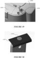
- the filter top panel 1101 comprises a handling feature to aid in insertion and/or removal of the filter module 1001 from the filter receptacle 300 of the housing of the apparatus, such as when lifting the filter 1001 out of engagement with the filter receptacle 300.
- the filter handling feature comprises a ridge, groove, or grip.
- the filter handling feature may be provided at a periphery of the panel portion 1103 of the filter top panel 1101.
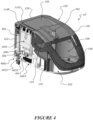
- the filter handling feature may be provided at a portion of the panel portion 1103 of the filter top panel that is adjacent the angled upper chassis surface 130 that is shown in figure 4 , to provide access to the handling feature.
- the filter handling feature may be provided elsewhere on the filter top panel 1011.
- the filter top panel comprises a plurality of filter handling features.
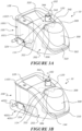
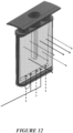
- a filter medium 1051 is associated with both the main compartment 1005 and the sub-compartment 1007, and is arranged to filter gases in, or exiting, the main compartment 1005 and the sub-compartment 1007.
- the filter medium 1051 covers or spans the main compartment 1005 and the sub-compartment 1007.
- the filter medium may span the main compartment and the plurality of sub-compartments.
- Figures 15 and 16 show a second configuration filter module 2001. Unless described below, the features, functionality, options, and advantages are all as outlined above for the first configuration, and like reference numerals indicate like parts with 1000 added to each numeral.
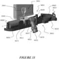
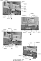
- the third configuration filter module 3001 is suitable for use with a valve module 9001 configured to sealingly and fluidly engage the filter extension duct 3046, such as that shown in figure 33 to 37D for example.
- the filter extension duct 3046 receives all oxygen or other gas from the valve manifold gases outlet 9019, to which it is sealingly engaged.
- the sub-compartment 3041 is sized relative to the main filter compartment 3005 to maximise the area for the ambient air to pass through filter.
- the area of the sub-compartment 3041 can be smaller than if the valve module was not sealingly engaged with the filter extension duct.
- the rear wall 11021 of the filter body 11003 has a pair of projections 11090 that provide an area for attaching the filter medium to the filter body 11003.
- the projections are preferably ultrasonic weld features that provide increased surface area for attaching the filter medium 11003.
- the projections 11090 are positioned generally centrally along the length of the filter body 11003 and are spaced apart from each other across the width of the filter body 11003.
- the projections 11090 are shaped as a cross.
- the projections 11090 support the filter medium to help achieve a consistent filter height.
- the projections 11090 are integrally moulded with the filter body 11003.
- the seal may comprise a compliant material that is overmoulded onto the lower body portion 11035.
- the lower wiper seal may taper outwardly; i.e., an outward portion of the lower wiper seal may be thinner than a more inward portion of the wiper seal. The soft seal seals between the lower body portion 11035 and the wall of the filter receptacle 300 when the filter body is positioned in the filter receptacle 300, to provide sealing engagement between the filter and the filter receptacle and to inhibit bacteria entry into the filter.
- the filter may be a double-sided filter, with opposed gases outlets on opposite sides of the filter body.
- Filter medium(s) may be provided on two opposing faces of the filter to filter gases exiting the two opposed gases outlets from the compartments/sub-compartments. Air and/or gases may exit the filter body on the opposing sides/of the filter module. This may further reduce pressure loss and increase the filter life due to the increased filter surface area.
- the ratios may be double those described above.
- a 'sheet' of filter medium is provided on a face of the filter body.
- the filter medium may be pleated to provide additional filter medium surface area.
- the described filters 1001, 2001, 3001, 11001 are able to filter gases from multiple sources, which avoids the use of multiple filters for different sources.
- Filter configurations having gases inlet ports located in different parts of the filter provide particular versatility by enabling coupling of gases sources from above and below the apparatus housing.
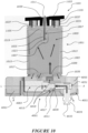
- valve module 4001 is substantially received within the housing, when the valve module is engaged with the housing it becomes integrated with the housing and does not increase the size or bulk of the housing. Additionally, the components of the valve module such as the valve 4003 and valve manifold 4011 described below are protected in use because they are positioned within the valve carrier 4051 and main housing of the apparatus in use. This configuration significantly reduces the likelihood of damage of the valve module and valve module components if the apparatus 10 is inadvertently knocked or dropped.
- the valve module comprises a flow control valve 4003 that is arranged to control a flow of gas through a valve manifold 4011.
- the valve is arranged to control a flow of gas into part of the apparatus.
- the valve may be arranged to control a flow of gas to a filter module 1001, 2001, 3001, 11001.
- the valve 4003 may be arranged to control a flow of gas to another part of the apparatus.
- the valve module 4001 and filter module 1001, 2001, 3001, 11001 are positioned upstream of the blower 402 and motor and/or sensor module 400.
- the valve module 4001 and filter module 1001, 2001, 3001, 11001 are positioned downstream of the blower 402.
- the flow control valve could be a solenoid valve, could be motor-driven, or could be piezo-operated for example.
- valve member In a solenoid valve, the valve member is actuated between open and closed positions.
- the solenoid valve may be a proportional valve. The extent of gas flow through the valve (i.e. due to the size of the valve opening) is relative to the electrical current supplied to the valve.
- the solenoid valve may be controlled with a modulated input signal, so that the valve is modulated between open and closed positions.
- the valve 4003 could be a needle valve, plunger valve, gate valve, ball valve, butterfly valve, globe valve, etc.
- the valve may be of the pressure compensated type.
- the valve is a normally-closed valve; that is, the valve is closed when powered off. That will prevent a connected gas supply line continuously releasing oxygen or other gas when the apparatus is powered off.
- the valve is a normally-open valve.
- An end 4018 of the valve manifold 4011 opposite to the gases inlet receives and sealingly engages with the valve 4003 such that the valve and valve manifold are in fluid communication.
- the end 4018 comprises a flange 4023 to mount to the valve.
- the flange 4023 has apertures 4023A to receive fasteners 4023F to fasten the manifold to the valve 4003.
- O-ring(s) may be provided about the periphery of the interface between the valve 4003 and the valve manifold 4011 to sealingly engage the valve with the valve manifold.
- the valve manifold 4011 has a shape that is complementary to the shape of the valve 4003.
- the valve manifold 4011 has a substantially cylindrical body
- the valve 4003 has a substantially cylindrical body.
- the valve manifold and valve may have different shapes, such as block, square, rectangular, or non-cylindrical.
- the configuration shown is lighter and cheaper to manufacture than a heavy block manifold.
- the substantially cylindrical manifold body may be formed from a continuous cylindrical rod that is fed into an automatic production machine.
- the valve manifold may be made using any suitable technique, such as CNC lathe or mill production for example.
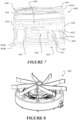
- the valve manifold 4011 directs/disperses oxygen from the valve via radially located gases outlets 4019.
- a single gases outlet 4019 is provided in the valve manifold. As oxygen passes through the outlet(s), noise is generated. Because the apparatus may be used in medical and/or home environments in close proximity to the patient, it is desirable to minimise the noise produced.
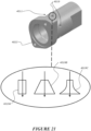
- the radial valve manifold gases outlet(s) 4019 may be aeroacoustically shaped to reduce noise.
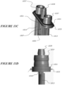
- the valve manifold gases outlet(s) may be one or, or a combination of, cylindrical through-holes 4019A, frustoconical 4019B, or flared 4019C in shape.
- the frustoconical and flared shapes may be such that the cross-sections enlarge in the direction of gas flow through the outlet(s) 4019.
- a hood, duct, or channel may be formed around, in proximity to, or in fluid communication with the valve manifold outlet(s) 4019 in order to reduce noise. Additionally and/or alternatively, foam, or the like, may be placed around the valve manifold, in proximity to the valve manifold outlets, to reduce noise.
- a small filter may be provided inside the valve manifold gases inlet 4017 inlet to prevent the introduction of dust or particulates into the valve.
- the valve manifold and swivel connector may be threaded to engage the components together.
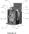
- the swivel connector 4031 has a gases inlet 4033 that is oriented substantially transversely relative to a longitudinal axis LA of the valve manifold, and that is in fluid communication, by a gas flow path 4037, with a swivel connector gases outlet 4039.
- the gases inlet 4033 of the swivel connector is formed in a transversely extending conduit/coupling 4035 that is fluidly connectable to a gas supply line.
- the conduit/coupling 4035 may connect to a gas supply line connector to deliver gases such as oxygen to the valve manifold.
- the gas supply line connector can be chosen depending on the country of use; for example, DISS and NIST medical gas connectors would typically be used in USA and Europe respectively.
- the swivel connector 4031 is arranged to provide a fluid connection between the gas supply line and the gases inlet 4017 of the valve manifold.
- the swivel connector additionally reduces the force exerted on the apparatus housing by the connected gas supply line. For example, when the apparatus is mounted on a pole, the weight of the hanging tube may place a strain on the apparatus.
- the swivel connector enables the gas supply line to be directed out of the way and secured to the pole.
- the valve carrier may have one or more guards 10085, 10086, 10087 to prevent damage to the main apparatus housing.
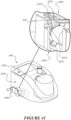
- Figure 43 shows the valve carrier having three guards 10085, 10086, 10087 that extend along the edges of the valve carrier that the swivel might strike, preventing the swivel striking the main apparatus housing.
- the guards 10085, 10086, 10087 are shown as integral features of the valve carrier parts. Alternatively, the guards 10085, 10086, 10087 may be separate features that are attached to the valve carrier.
- valve module In the event of damage to the valve module, the valve module is replaceable without requiring disassembly of the overall apparatus.
- the valve module 4001 is located at the start of the flow path of the apparatus. If the valve 4003 was to be obstructed (i.e. by dust, particulate, etc.) such that it would be held open, excess pressurised oxygen or other gas would 'dump' out ambient air entry opening(s) in the valve carrier 4051 (e.g. the opening shown beneath the swivel connector in figure 18 ). This would prevent any excess pressure reaching the patient. As such, the system may be considered inherently pressure limited without the use of a pressure relief valve.
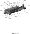
- the valve module 4001 comprises a valve carrier 4051 that substantially contains and supports the valve 4003, the valve manifold 4011, and the swivel connector 4031.
- the valve carrier 4011 is removably engageable with the housing of the apparatus.
- An exterior part of the valve carrier is arranged to be substantially flush with an external wall of the apparatus housing when the valve module is removably engaged with the housing.
- the valve carrier 4051 comprises a first, lower valve carrier part 4053 and optionally, a second, upper valve carrier part.
- the valve, valve manifold, and swivel connector are secured in place at least partly between the first valve carrier part 4053 and the second valve carrier part and are fixed relative to the valve carrier (other than the swivelling gases inlet 4033).
- the first valve carrier part may comprise a first side part and the second valve carrier part may comprise a second side part.
- the valve, valve manifold, and swivel connector may be coupled to, and in secured in place by, the lower valve carrier part 4053.
- the valve carrier 4051 may be retained in the recess of the housing by fasteners, a permanent or temporary snap-fit, or any other suitable way.
- the apparatus may simultaneously draw in gas from the gases inlet of the valve manifold and ambient air, or the pressurisation of gas from the gases inlet may force that gas through the filter.
- the gases will exit the valve module and enter the gases inlets in the filter.
- the apparatus may be configured such that the gas from the gases inlet and the ambient air are dynamically entrained/mixed in the apparatus prior to being delivered to the gases outlet of the apparatus.
- the valve module may be configured to minimise pressure drop across the valve module by having one or more of: the large opening 4051O for ambient air located around the swivel connector and/or elsewhere; radiuses/rounded/sloped edges in the flow path (i.e. inside the valve manifold, for example) to minimise turbulence and smooth flow.
- the above first configuration valve module 4001 utilises a fixed valve manifold 4011 with a swivel connector 4031 attached.
- This second configuration valve module 5001 differs in that the valve manifold 5011 swivels/rotates within the valve carrier 5051, the valve 5003 is rotatable with the valve manifold 5011, and a gas supply line may connect directly to the gases inlet 5015 of the valve manifold.
- the valve manifold 5011 and valve 5003 are rotatable inside swivel bearings 5061 that are provided between the valve and valve manifold and the valve carrier 5051.
- the valve manifold 5011 and valve 5003 may be configured to rotate within, and may be supported and/or held in place by, ribs or other integrally moulded support features in the valve carrier 5051.
- valve manifold gases inlet 5015 extends substantially transversely relative to a longitudinal axis of the valve manifold, and is fluidly connectable to a gas supply line, and the valve and valve manifold are rotatable relative to the valve carrier about the longitudinal axis LA of the valve manifold 5011.
- the valve manifold 6011 is configured to swivel or rotate within, and may be supported and/or held in place by, ribs or other integrally moulded support features in the valve carrier 6051.
- the flow channels that direct oxygen or other gases upward from the manifold gases outlets 6019 upward toward the filter 1001, 2001, 3001, 11001 reduce or prevent the loss of oxygen from the system. As a result, oxygen entrainment efficiency is enhanced.
- oxygen entrainment in the air flow is enhanced by the flow channels 7054 and duct 7063 directing oxygen flow upward toward the filter.
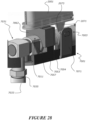
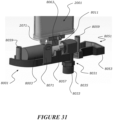
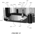
- Figure 31 shows a fifth configuration valve module 8001.
- the features, functionality, options, and advantages are all as outlined above for the first valve module configuration above, and like reference numerals indicate like parts with 4000 added to each numeral.
- the filter 10246c may be or comprise a sintered metal filter.
- suitable sintered metals include copper, bronze, or steel.
- the filter may be a ceramic or polymeric filter, which may be sintered filters. Sintered metal filters provide long term reliability, and due to the proximity to the oxygen supply source the resulting pressure drop would not be prohibitive.
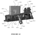
- the upper valve carrier part 9055 has the effect of 'sandwiching' the valve 9003, valve manifold 9011, and speaker 9066 in place on the valve carrier 9051. Specifically, the upper valve carrier part 9055 supports the valve 9003, valve manifold 9011 and speaker 9066 from above. This assists in the assembly of the valve module 9001 and in retaining all components together as a complete module during transport.
- Sleeves 9060 are provided in the upper carrier part to receive fasteners from sleeves 9059 in the lower carrier part.
- grommets provide a seal between the wires and an opening that the wires pass through, and shield the wires from contact with the edges of the opening that the wires pass through.
- the upper valve carrier part 9055 has an electrical connector, such as a PCB 9067, extending therethrough.
- the PCB 9067 is part of the lower chassis 202 of the apparatus 10, and couples with a PCB edge connector in the valve carrier 9051 so that the PCB 9067 is in electronic communication with the valve 9003, temperature sensor, and speaker 9066, and so that the valve module 9001 and apparatus 10 are in electronic communication.
- the PCB 9067 is orientated vertically.
- the PCB 9067 may be provided in the valve module, and the PCB may project from a housing of the valve carrier to engage with a complementary edge connector internal to the apparatus 10, such that the valve module 9001 and apparatus 10 control system are in electronic communication.
- the electrical connector is shown as being accessible from the top of the valve carrier, in some configurations, the electrical connector may be positioned in, or accessible from, a top, side, or base of the valve carrier.
- the flexible PCB 10067 has two outwardly extending tabs 10068 that electronically connect to the speaker 10066.
- the flexible PCB 10067 could have a differently shaped end to connect to the speaker 10066.
- the shape of the end of the flexible PCB 10067 will be chosen or designed depending on the shape of the speaker, other components, or the necessary connection of the flexible PCB.
- the end of the flexible PCB 10067 adjacent the speaker is oriented with the width of the ribbon extending horizontally. Extending from the speaker, the flexible PCB 10067 then twists from the horizontal orientation to a vertical orientation in which the width of the ribbon is now oriented vertically.
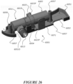
- the vertically oriented section of the flexible PCB 10067 is supported in stands 10076, 10077, and 10078 of the lower valve carrier part 10053.
- the flexible PCB 10067 is shaped with two steps, with ramps between the steps. The shape and orientation of the flexible PCB 10067 reduces the space required for the flexible PCB 10067.
- the next portion 10072 of the flexible PCB 10067 extends vertically; that is, the ribbon is oriented with the length extending vertically. This portion 10072 and has a slight twist.
- the end 10073 of the flexible PCB 10067 electronically connects to the apparatus 10 control system.
- the flexible PCB 10067 also includes an extension 10074 that connects to the temperature sensor.
- the extension 10074 is an L-shaped extension with the width of the ribbon oriented horizontally. The shape and orientation of the extension 10074 will be chosen or designed depending on the relative position of the components.
- the extension 10074 is oriented to lie horizontally and is supported by a stand of the lower valve carrier part 10053.
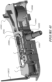
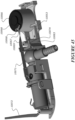
- Figures 43 shows an alternative embodiment of the upper valve carrier part 10055 having a spacer 10080 to assist with securing the speaker 10066 rigidly.
- the spacer 10080 contacts the components above and prevents the upper valve carrier part 10055 from moving, such as flexing.
- the spacer 10080 extends upwardly from the upper valve carrier part 10055.
- the spacer 10080 prevents, or at least substantially inhibits, the speaker 10066 from moving relative to the other components during transport.
- Figures 52 , and 56 to 58 show a variation of the embodiment of figures 43 to 45 .
- the swivel connector is a ball joint 14005.
- the swivel connector is a ball joint for providing rotation in multiple directions.
- the ball joint 14005 will pivot about a single axis of rotation.
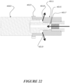
- This arrangement provides a tight fit between the valve carrier and the swivel connector regardless of the position of the swivel connector. This prevents, or at least substantially inhibits oxygen from leaking into the underside of the apparatus, and instead directs it out around the swivel connector.
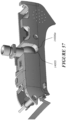
- the valve carrier has a cup shaped surface 14006a to receive the ball of the swivel joint. In this embodiment, ambient air is drawn through one or more gaps that occur when the valve carrier is assembled. This is shown in figure 57 .
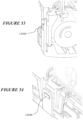
- the filter module engagement tab 3071 includes an aperture therethrough.
- the intermediary filter clip 9074 (see figure 34 ) includes an aperture with an internal projection.
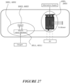
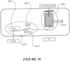
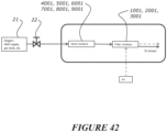
- the manually adjusted oxygen supply 21 may be manually controlled by a user via an external flow controller 22, such as a wall supply rotameter or gas tank valve for example.
- This configuration also provides the apparatus 10 a capacity to shut-off or control the manually adjusted oxygen supply in exceptional or unsafe circumstances - such as excessive pressure or if the patient was to become hyperoxic (excess blood oxygen retention).
- the swivel connector may be arranged to provide both swivelling and translational movement; so that the gases inlet of the swivel connector may both swivel about one or more axes and may also travel linearly for example. This may be practical for translating the gases inlet from one portion of the apparatus to another, such as from one side of the apparatus to the other of the apparatus for example. In some configurations, the gases inlet may be arranged to translate instead of rotate.
- the configuration could be such that the liquid chamber is inserted into and removed from the chamber bay from a side, rear, or top of the housing.
Landscapes
- Health & Medical Sciences (AREA)
- Anesthesiology (AREA)
- Emergency Medicine (AREA)
- Pulmonology (AREA)
- General Health & Medical Sciences (AREA)
- Public Health (AREA)
- Heart & Thoracic Surgery (AREA)
- Hematology (AREA)
- Life Sciences & Earth Sciences (AREA)
- Animal Behavior & Ethology (AREA)
- Engineering & Computer Science (AREA)
- Biomedical Technology (AREA)
- Veterinary Medicine (AREA)
- Filtering Of Dispersed Particles In Gases (AREA)
- Otolaryngology (AREA)
- Valve Housings (AREA)
- Separation Using Semi-Permeable Membranes (AREA)
- Water Treatment By Sorption (AREA)
- Other Investigation Or Analysis Of Materials By Electrical Means (AREA)
- Infusion, Injection, And Reservoir Apparatuses (AREA)
Priority Applications (1)
| Application Number | Priority Date | Filing Date | Title |
|---|---|---|---|
| EP26152132.2A EP4706727A3 (de) | 2016-10-18 | 2017-10-18 | Vorrichtung zum zuführen eines gasstroms |
Applications Claiming Priority (4)
| Application Number | Priority Date | Filing Date | Title |
|---|---|---|---|
| US201662409543P | 2016-10-18 | 2016-10-18 | |
| US201762488841P | 2017-04-23 | 2017-04-23 | |
| PCT/NZ2017/050136 WO2018074935A1 (en) | 2016-10-18 | 2017-10-18 | Valve module and filter |
| EP17861903.7A EP3528879B1 (de) | 2016-10-18 | 2017-10-18 | Filter |
Related Parent Applications (1)
| Application Number | Title | Priority Date | Filing Date |
|---|---|---|---|
| EP17861903.7A Division EP3528879B1 (de) | 2016-10-18 | 2017-10-18 | Filter |
Related Child Applications (2)
| Application Number | Title | Priority Date | Filing Date |
|---|---|---|---|
| EP26152132.2A Division EP4706727A3 (de) | 2016-10-18 | 2017-10-18 | Vorrichtung zum zuführen eines gasstroms |
| EP26152132.2A Division-Into EP4706727A3 (de) | 2016-10-18 | 2017-10-18 | Vorrichtung zum zuführen eines gasstroms |
Publications (3)
| Publication Number | Publication Date |
|---|---|
| EP4397347A2 true EP4397347A2 (de) | 2024-07-10 |
| EP4397347A3 EP4397347A3 (de) | 2024-08-28 |
| EP4397347B1 EP4397347B1 (de) | 2026-02-18 |
Family
ID=62018668
Family Applications (3)
| Application Number | Title | Priority Date | Filing Date |
|---|---|---|---|
| EP17861903.7A Active EP3528879B1 (de) | 2016-10-18 | 2017-10-18 | Filter |
| EP26152132.2A Pending EP4706727A3 (de) | 2016-10-18 | 2017-10-18 | Vorrichtung zum zuführen eines gasstroms |
| EP24166370.7A Active EP4397347B1 (de) | 2016-10-18 | 2017-10-18 | Vorrichtung zum zuführen eines gasstroms |
Family Applications Before (2)
| Application Number | Title | Priority Date | Filing Date |
|---|---|---|---|
| EP17861903.7A Active EP3528879B1 (de) | 2016-10-18 | 2017-10-18 | Filter |
| EP26152132.2A Pending EP4706727A3 (de) | 2016-10-18 | 2017-10-18 | Vorrichtung zum zuführen eines gasstroms |
Country Status (10)
| Country | Link |
|---|---|
| US (3) | US11202878B2 (de) |
| EP (3) | EP3528879B1 (de) |
| JP (3) | JP7184766B2 (de) |
| KR (3) | KR102821777B1 (de) |
| CN (1) | CN110072584A (de) |
| AU (3) | AU2017346325B2 (de) |
| CA (1) | CA3040381A1 (de) |
| GB (3) | GB2601065B (de) |
| SG (1) | SG11201903239VA (de) |
| WO (1) | WO2018074935A1 (de) |
Families Citing this family (14)
| Publication number | Priority date | Publication date | Assignee | Title |
|---|---|---|---|---|
| SG11201903239VA (en) | 2016-10-18 | 2019-05-30 | Fisher & Paykel Healthcare Ltd | Valve module and filter |
| WO2020095186A1 (en) | 2018-11-05 | 2020-05-14 | Fisher & Paykel Healthcare Limited | Breathing assistance apparatus and/or components thereof |
| EP3708208B1 (de) * | 2019-02-20 | 2022-06-08 | Löwenstein Medical Technology S.A. | Vorrichtung zur beatmung mit pneumatikstrang |
| DE102020001389A1 (de) | 2019-03-07 | 2020-09-10 | Löwenstein Medical Technology S.A. | Beatmungsgerät mit einer Mischkammer und Mischkammer für ein Beatmungsgerät |
| US20220143356A1 (en) * | 2019-06-06 | 2022-05-12 | Vincent Medical (Dong Guoan) Manufacturing Co., Ltd. | Dew point sensor system, method for modulating a humidifier heater plate, and humidifier/medical device containing |
| CN113365682A (zh) * | 2019-06-06 | 2021-09-07 | 东莞永胜医疗制品有限公司 | 带有噪声阻尼构件的呼吸设备 |
| DE102019119674A1 (de) * | 2019-07-19 | 2021-01-21 | Hamilton Medical Ag | Beatmungsleitung mit verbessert austauschbarem Atemgas-Filter |
| WO2021016482A1 (en) * | 2019-07-24 | 2021-01-28 | Bunnell Incorporated | Pulmonary ventilator with changeable filters |
| CN110801678B (zh) * | 2019-11-19 | 2021-07-16 | 温岭市亚超童鞋业有限公司 | 一种重污染废气净化用仿蒲公英自脱落式过滤装置 |
| FR3108261B1 (fr) * | 2020-03-18 | 2024-08-09 | Air Liquide Medical Systems | Ventilateur médical à entrées d’air protégées par des filtres amovibles |
| CN112773996B (zh) * | 2021-01-27 | 2024-12-17 | 天津仟易鑫科技发展有限公司 | 一种麻醉药液挥发器 |
| US20240181188A1 (en) | 2021-03-08 | 2024-06-06 | Fisher & Paykel Healthcare Limited | Alarm for breathing assistance system |
| CN118512691A (zh) | 2021-04-30 | 2024-08-20 | 费雪派克医疗保健有限公司 | 患者接口 |
| AU2024226652A1 (en) | 2023-02-24 | 2025-09-11 | Fisher & Paykel Healthcare Limited | Patient interface |
Family Cites Families (57)
| Publication number | Priority date | Publication date | Assignee | Title |
|---|---|---|---|---|
| DE3600373C2 (de) * | 1985-02-12 | 1995-06-01 | Fev Motorentech Gmbh | Partikelfiltersystem mit porösem Filtermaterial für gasförmige Medien |
| DE3817985A1 (de) * | 1988-05-27 | 1989-12-07 | Salvia Werk Gmbh | Geraet zur unterstuetzung der spontanen atmung eines patienten |
| GB8911627D0 (en) * | 1989-05-19 | 1989-07-05 | Intersurgical Guernsey Ltd | Improvements in filters |
| SE503089C2 (sv) * | 1991-09-20 | 1996-03-25 | Gibeck Respiration Ab | Anordning för anslutning av en patient till en respirator innefattande en fuktvärmeväxlare samt användning av en fuktvärmeväxlare i denna anordning |
| US5357950A (en) * | 1993-03-02 | 1994-10-25 | Comasec International S.A. | Breath actuated positive pressure demand regulator with override |
| JP3013926U (ja) | 1995-01-24 | 1995-07-25 | 株式会社大和酸器西 | 医療ガス用アダプタプラグ |
| JPH1015070A (ja) | 1996-06-28 | 1998-01-20 | Japan Gore Tex Inc | 医療用ガス加湿器および医療用ガス供給装置 |
| SE9603612D0 (sv) * | 1996-10-03 | 1996-10-03 | Siemens Elema Ab | Metod för funktionskontroll av filter |
| US6024087A (en) * | 1997-10-09 | 2000-02-15 | Ohmeda Inc. | Emergency oxygen flowmeter arrangement |
| AU5441599A (en) * | 1998-09-04 | 2000-03-27 | Caradyne (R & D) Limited | A continuous positive airway pressure controller |
| US6217627B1 (en) * | 1999-06-29 | 2001-04-17 | Siemens Canada Limited | Cam operated drawer style air cleaner |
| US6318364B1 (en) | 1999-07-05 | 2001-11-20 | Be Intellectual Property, Inc. | Modular drop out container for aircraft oxygen masks |
| US6619287B2 (en) * | 2000-03-02 | 2003-09-16 | Fisher & Paykel Limited | Filter |
| US6513522B1 (en) * | 2000-06-13 | 2003-02-04 | Mallinckrodt Inc. | Wearable storage system for pressurized fluids |
| DE10049313A1 (de) * | 2000-10-05 | 2002-04-11 | Audi Ag | Gehäuse zur Aufnahme eines Luftfilterelements |
| WO2002051486A1 (en) * | 2000-12-22 | 2002-07-04 | Resmed Ltd. | Flow regulation vent |
| US20030062040A1 (en) * | 2001-09-28 | 2003-04-03 | Lurie Keith G. | Face mask ventilation/perfusion systems and method |
| US6966316B2 (en) * | 2002-06-24 | 2005-11-22 | Survivair Respirators, Inc. | Clean gas purge for breathing gas regulator |
| US6866700B2 (en) * | 2002-08-27 | 2005-03-15 | Ag Industries | Filter housing assembly for use in oxygen concentrators and other compressors |
| US7070642B2 (en) * | 2002-10-28 | 2006-07-04 | Donaldson Company, Inc. | Air cleaner; replaceable filter cartridges; and, methods |
| US7628152B2 (en) * | 2003-04-25 | 2009-12-08 | Sti Licensing Corp. | Breathing regulator with nonlinear positive pressure spring |
| CA2533759C (en) * | 2003-08-01 | 2011-11-15 | Fisher & Paykel Healthcare Limited | Device for supplying a respiratory gas with integrated humidifier |
| AU2006244856A1 (en) * | 2005-05-06 | 2006-11-16 | Teijin Pharma Limited | Silencer and oxygen concentration device using the same |
| ATE536904T1 (de) * | 2005-06-23 | 2011-12-15 | Resmed Paris | Gerät zur unterstützung der atmung |
| EP3434332B1 (de) * | 2005-07-01 | 2023-12-20 | Fisher & Paykel Healthcare Limited | Atmungsunterstützungsvorrichtung mit einem verteiler zum hinzufügen von hilfsgasen zu umgebungsgasen |
| DE102005038349B4 (de) | 2005-08-11 | 2008-04-10 | Fritz Stephan Gmbh | Pneumatischer Nebenwiderstand sowie Gasmischer |
| US7677246B2 (en) | 2005-09-23 | 2010-03-16 | Ric Investments, Llc | Modular pressure support system |
| US20070221221A1 (en) | 2006-02-23 | 2007-09-27 | Cooke Richard H | Ventilator for Rapid Response to Respiratory Disease Conditions |
| DE102006011151B4 (de) | 2006-03-10 | 2022-01-20 | Löwenstein Medical Technology S.A. | Vorrichtung zur Beatmung |
| US20080066752A1 (en) | 2006-09-20 | 2008-03-20 | Nellcor Puritan Bennett Inc. | Method and system for circulatory delay compensation in closed-loop control of a medical device |
| JP2008073212A (ja) * | 2006-09-21 | 2008-04-03 | Atom Medical Corp | 保育器用酸素濃度制御装置 |
| WO2008102216A1 (en) * | 2007-02-20 | 2008-08-28 | Resmed Paris | Gas supply unit for a respiratory system |
| EP2113278B1 (de) * | 2007-05-21 | 2012-08-15 | Covidien AG | Medizinischer Wärme- und Flüssigkeitstauscher |
| GB2450735B (en) * | 2007-07-05 | 2012-11-28 | Air Safety Ltd | Air filter assembly |
| CA2712481A1 (en) | 2008-01-18 | 2009-07-23 | Breathe Technologies, Inc. | Methods and devices for improving efficacy of non-invasive ventilation |
| WO2009093977A1 (en) | 2008-01-25 | 2009-07-30 | Flodins Filter Aktiebolag | Filter |
| US7833308B2 (en) * | 2008-01-30 | 2010-11-16 | Home Health Medical Equipment, Inc. | Filter assembly with multiple inlets and multiple filter members |
| WO2009123977A1 (en) | 2008-03-31 | 2009-10-08 | Nellcor Puritan Bennett Llc | Ventilator based on a fluid equivalent of the "digital to analog voltage" concept |
| US8468637B2 (en) * | 2009-02-06 | 2013-06-25 | Endoclear Llc | Mechanically-actuated endotracheal tube cleaning device |
| US20100242961A1 (en) | 2009-03-31 | 2010-09-30 | Nellcor Puritan Bennett Llc | Systems and methods for preventing water damage in a breathing assistance system |
| EP2317150B1 (de) * | 2009-10-29 | 2019-12-18 | ResMed Pty Ltd | Patientenbeatmungsvorrichtung und Komponenten davon |
| US20110126832A1 (en) * | 2009-12-01 | 2011-06-02 | Nellcor Puritan Bennett Llc | Exhalation Valve Assembly |
| EP2425869A1 (de) | 2010-09-07 | 2012-03-07 | Imt Ag | Beatmungsgerät und/oder Anästhesiegerät |
| DE202011107902U1 (de) | 2010-11-15 | 2012-01-11 | GRÜNDLER GmbH | Y-Stück |
| WO2012160477A1 (en) | 2011-05-20 | 2012-11-29 | Koninklijke Philips Electronics N.V. | Rotating electrical connector and respiratory gas delivery system employing same |
| US10004856B2 (en) * | 2011-12-01 | 2018-06-26 | Buffalo Filter Llc | Filtration system and method |
| GB2500061B (en) * | 2012-03-09 | 2018-11-28 | Intersurgical Ag | Connector for respiratory ducts |
| EP3799911B1 (de) * | 2012-05-18 | 2023-05-31 | ResMed Pty Ltd | Nasalmaskensystem |
| EP4390201A3 (de) | 2012-08-08 | 2024-08-28 | Fisher & Paykel Healthcare Limited | Beatmungsschläuche mit schwenkbarem bogen |
| US9272115B2 (en) * | 2012-11-26 | 2016-03-01 | Hill-Rom Services Pte Ltd. | Respiratory therapy device and filtration units therefor |
| EP3219350B1 (de) * | 2013-06-28 | 2020-04-01 | Vyaire Medical Capital LLC | Ventilatorsystem |
| WO2015142405A1 (en) * | 2014-03-21 | 2015-09-24 | Life Technologies Corporation | Gas filter systems for fluid processing systems |
| WO2015187986A1 (en) * | 2014-06-04 | 2015-12-10 | Free Air, Inc. | Systems and methods for removing ultra-fine particles from air |
| US11571539B2 (en) * | 2014-07-21 | 2023-02-07 | Fisher & Paykel Healthcare Limited | Fluid mixing structure |
| CN205181939U (zh) | 2014-08-08 | 2016-04-27 | 康尔福盛2200公司 | 气道适配器组件 |
| US9864603B2 (en) | 2014-09-26 | 2018-01-09 | Intel Corporation | Instruction and logic for machine check interrupt management |
| SG11201903239VA (en) | 2016-10-18 | 2019-05-30 | Fisher & Paykel Healthcare Ltd | Valve module and filter |
-
2017
- 2017-10-18 SG SG11201903239VA patent/SG11201903239VA/en unknown
- 2017-10-18 WO PCT/NZ2017/050136 patent/WO2018074935A1/en not_active Ceased
- 2017-10-18 EP EP17861903.7A patent/EP3528879B1/de active Active
- 2017-10-18 KR KR1020237005495A patent/KR102821777B1/ko active Active
- 2017-10-18 CA CA3040381A patent/CA3040381A1/en active Pending
- 2017-10-18 AU AU2017346325A patent/AU2017346325B2/en active Active
- 2017-10-18 JP JP2019520897A patent/JP7184766B2/ja active Active
- 2017-10-18 GB GB2118784.4A patent/GB2601065B/en active Active
- 2017-10-18 KR KR1020197014163A patent/KR102502012B1/ko active Active
- 2017-10-18 EP EP26152132.2A patent/EP4706727A3/de active Pending
- 2017-10-18 CN CN201780076725.0A patent/CN110072584A/zh active Pending
- 2017-10-18 GB GB2200099.6A patent/GB2606608B/en active Active
- 2017-10-18 GB GB1906909.5A patent/GB2570094B/en active Active
- 2017-10-18 US US16/342,472 patent/US11202878B2/en active Active
- 2017-10-18 EP EP24166370.7A patent/EP4397347B1/de active Active
- 2017-10-18 KR KR1020257019525A patent/KR20250091325A/ko active Pending
-
2021
- 2021-10-22 US US17/451,934 patent/US12383694B2/en active Active
-
2022
- 2022-09-16 JP JP2022148301A patent/JP7534362B2/ja active Active
-
2023
- 2023-09-15 AU AU2023229605A patent/AU2023229605B2/en active Active
-
2024
- 2024-08-01 JP JP2024126088A patent/JP2024167216A/ja active Pending
-
2025
- 2025-07-09 US US19/264,130 patent/US20260061151A1/en active Pending
- 2025-10-22 AU AU2025256116A patent/AU2025256116A1/en active Pending
Also Published As
Similar Documents
| Publication | Publication Date | Title |
|---|---|---|
| AU2023229605B2 (en) | Valve module and filter | |
| EP1648545B1 (de) | Vorrichtung zur zufuhr eines atemgases mit integriertem befeuchter | |
| EP1933910B1 (de) | Modulares druckunterstützungssystem | |
| US20210205554A1 (en) | Ventilator apparatus and method | |
| GB2601641A (en) | Valve module and filter | |
| GB2606609A (en) | Valve module and filter |
Legal Events
| Date | Code | Title | Description |
|---|---|---|---|
| PUAI | Public reference made under article 153(3) epc to a published international application that has entered the european phase |
Free format text: ORIGINAL CODE: 0009012 |
|
| STAA | Information on the status of an ep patent application or granted ep patent |
Free format text: STATUS: THE APPLICATION HAS BEEN PUBLISHED |
|
| AC | Divisional application: reference to earlier application |
Ref document number: 3528879 Country of ref document: EP Kind code of ref document: P |
|
| AK | Designated contracting states |
Kind code of ref document: A2 Designated state(s): AL AT BE BG CH CY CZ DE DK EE ES FI FR GB GR HR HU IE IS IT LI LT LU LV MC MK MT NL NO PL PT RO RS SE SI SK SM TR |
|
| PUAL | Search report despatched |
Free format text: ORIGINAL CODE: 0009013 |
|
| AK | Designated contracting states |
Kind code of ref document: A3 Designated state(s): AL AT BE BG CH CY CZ DE DK EE ES FI FR GB GR HR HU IE IS IT LI LT LU LV MC MK MT NL NO PL PT RO RS SE SI SK SM TR |
|
| RIC1 | Information provided on ipc code assigned before grant |
Ipc: A61M 16/20 20060101AFI20240723BHEP |
|
| STAA | Information on the status of an ep patent application or granted ep patent |
Free format text: STATUS: REQUEST FOR EXAMINATION WAS MADE |
|
| 17P | Request for examination filed |
Effective date: 20250227 |
|
| GRAP | Despatch of communication of intention to grant a patent |
Free format text: ORIGINAL CODE: EPIDOSNIGR1 |
|
| STAA | Information on the status of an ep patent application or granted ep patent |
Free format text: STATUS: GRANT OF PATENT IS INTENDED |
|
| INTG | Intention to grant announced |
Effective date: 20250916 |
|
| GRAS | Grant fee paid |
Free format text: ORIGINAL CODE: EPIDOSNIGR3 |
|
| GRAA | (expected) grant |
Free format text: ORIGINAL CODE: 0009210 |
|
| STAA | Information on the status of an ep patent application or granted ep patent |
Free format text: STATUS: THE PATENT HAS BEEN GRANTED |
|
| AC | Divisional application: reference to earlier application |
Ref document number: 3528879 Country of ref document: EP Kind code of ref document: P |
|
| AK | Designated contracting states |
Kind code of ref document: B1 Designated state(s): AL AT BE BG CH CY CZ DE DK EE ES FI FR GB GR HR HU IE IS IT LI LT LU LV MC MK MT NL NO PL PT RO RS SE SI SK SM TR |
|
| REG | Reference to a national code |
Ref country code: CH Ref legal event code: F10 Free format text: ST27 STATUS EVENT CODE: U-0-0-F10-F00 (AS PROVIDED BY THE NATIONAL OFFICE) Effective date: 20260218 Ref country code: GB Ref legal event code: FG4D |
|
| REG | Reference to a national code |
Ref country code: IE Ref legal event code: FG4D |
|
| REG | Reference to a national code |
Ref country code: DE Ref legal event code: R096 Ref document number: 602017094003 Country of ref document: DE |
|
| P01 | Opt-out of the competence of the unified patent court (upc) registered |
Free format text: CASE NUMBER: UPC_APP_0009588_4397347/2026 Effective date: 20260311 |
|
| REG | Reference to a national code |
Ref country code: NL Ref legal event code: MP Effective date: 20260218 |
|
| PG25 | Lapsed in a contracting state [announced via postgrant information from national office to epo] |
Ref country code: RS Free format text: LAPSE BECAUSE OF FAILURE TO SUBMIT A TRANSLATION OF THE DESCRIPTION OR TO PAY THE FEE WITHIN THE PRESCRIBED TIME-LIMIT Effective date: 20260518 |
|
| PG25 | Lapsed in a contracting state [announced via postgrant information from national office to epo] |
Ref country code: ES Free format text: LAPSE BECAUSE OF FAILURE TO SUBMIT A TRANSLATION OF THE DESCRIPTION OR TO PAY THE FEE WITHIN THE PRESCRIBED TIME-LIMIT Effective date: 20260218 |
|
| PG25 | Lapsed in a contracting state [announced via postgrant information from national office to epo] |
Ref country code: PL Free format text: LAPSE BECAUSE OF FAILURE TO SUBMIT A TRANSLATION OF THE DESCRIPTION OR TO PAY THE FEE WITHIN THE PRESCRIBED TIME-LIMIT Effective date: 20260218 |
|
| PG25 | Lapsed in a contracting state [announced via postgrant information from national office to epo] |
Ref country code: GR Free format text: LAPSE BECAUSE OF FAILURE TO SUBMIT A TRANSLATION OF THE DESCRIPTION OR TO PAY THE FEE WITHIN THE PRESCRIBED TIME-LIMIT Effective date: 20260519 |
|
| REG | Reference to a national code |
Ref country code: LT Ref legal event code: MG9D |
|
| PG25 | Lapsed in a contracting state [announced via postgrant information from national office to epo] |
Ref country code: LT Free format text: LAPSE BECAUSE OF FAILURE TO SUBMIT A TRANSLATION OF THE DESCRIPTION OR TO PAY THE FEE WITHIN THE PRESCRIBED TIME-LIMIT Effective date: 20260218 |
|
| PG25 | Lapsed in a contracting state [announced via postgrant information from national office to epo] |
Ref country code: NO Free format text: LAPSE BECAUSE OF FAILURE TO SUBMIT A TRANSLATION OF THE DESCRIPTION OR TO PAY THE FEE WITHIN THE PRESCRIBED TIME-LIMIT Effective date: 20260518 |
|
| PG25 | Lapsed in a contracting state [announced via postgrant information from national office to epo] |
Ref country code: SE Free format text: LAPSE BECAUSE OF FAILURE TO SUBMIT A TRANSLATION OF THE DESCRIPTION OR TO PAY THE FEE WITHIN THE PRESCRIBED TIME-LIMIT Effective date: 20260218 Ref country code: FI Free format text: LAPSE BECAUSE OF FAILURE TO SUBMIT A TRANSLATION OF THE DESCRIPTION OR TO PAY THE FEE WITHIN THE PRESCRIBED TIME-LIMIT Effective date: 20260218 Ref country code: AT Free format text: LAPSE BECAUSE OF FAILURE TO SUBMIT A TRANSLATION OF THE DESCRIPTION OR TO PAY THE FEE WITHIN THE PRESCRIBED TIME-LIMIT Effective date: 20260218 |
|
| REG | Reference to a national code |
Ref country code: AT Ref legal event code: MK05 Ref document number: 1887430 Country of ref document: AT Kind code of ref document: T Effective date: 20260218 |
|
| PG25 | Lapsed in a contracting state [announced via postgrant information from national office to epo] |
Ref country code: HR Free format text: LAPSE BECAUSE OF FAILURE TO SUBMIT A TRANSLATION OF THE DESCRIPTION OR TO PAY THE FEE WITHIN THE PRESCRIBED TIME-LIMIT Effective date: 20260218 |
|
| PG25 | Lapsed in a contracting state [announced via postgrant information from national office to epo] |
Ref country code: PT Free format text: LAPSE BECAUSE OF FAILURE TO SUBMIT A TRANSLATION OF THE DESCRIPTION OR TO PAY THE FEE WITHIN THE PRESCRIBED TIME-LIMIT Effective date: 20260618 Ref country code: IS Free format text: LAPSE BECAUSE OF FAILURE TO SUBMIT A TRANSLATION OF THE DESCRIPTION OR TO PAY THE FEE WITHIN THE PRESCRIBED TIME-LIMIT Effective date: 20260618 |
|
| PG25 | Lapsed in a contracting state [announced via postgrant information from national office to epo] |
Ref country code: NL Free format text: LAPSE BECAUSE OF FAILURE TO SUBMIT A TRANSLATION OF THE DESCRIPTION OR TO PAY THE FEE WITHIN THE PRESCRIBED TIME-LIMIT Effective date: 20260218 |
|
| PG25 | Lapsed in a contracting state [announced via postgrant information from national office to epo] |
Ref country code: LV Free format text: LAPSE BECAUSE OF FAILURE TO SUBMIT A TRANSLATION OF THE DESCRIPTION OR TO PAY THE FEE WITHIN THE PRESCRIBED TIME-LIMIT Effective date: 20260218 |
|
| PG25 | Lapsed in a contracting state [announced via postgrant information from national office to epo] |
Ref country code: BG Free format text: LAPSE BECAUSE OF FAILURE TO SUBMIT A TRANSLATION OF THE DESCRIPTION OR TO PAY THE FEE WITHIN THE PRESCRIBED TIME-LIMIT Effective date: 20260218 |