EP4397341B1 - Geschmacksinhalator - Google Patents
Geschmacksinhalator Download PDFInfo
- Publication number
- EP4397341B1 EP4397341B1 EP24176266.5A EP24176266A EP4397341B1 EP 4397341 B1 EP4397341 B1 EP 4397341B1 EP 24176266 A EP24176266 A EP 24176266A EP 4397341 B1 EP4397341 B1 EP 4397341B1
- Authority
- EP
- European Patent Office
- Prior art keywords
- flavor
- holding member
- cylindrical holding
- cooling layer
- flow path
- Prior art date
- Legal status (The legal status is an assumption and is not a legal conclusion. Google has not performed a legal analysis and makes no representation as to the accuracy of the status listed.)
- Active
Links
Images

Classifications
-
- A—HUMAN NECESSITIES
- A24—TOBACCO; CIGARS; CIGARETTES; SIMULATED SMOKING DEVICES; SMOKERS' REQUISITES
- A24F—SMOKERS' REQUISITES; MATCH BOXES; SIMULATED SMOKING DEVICES
- A24F42/00—Simulated smoking devices other than electrically operated; Component parts thereof; Manufacture or testing thereof
- A24F42/20—Devices without heating means
-
- A—HUMAN NECESSITIES
- A24—TOBACCO; CIGARS; CIGARETTES; SIMULATED SMOKING DEVICES; SMOKERS' REQUISITES
- A24D—CIGARS; CIGARETTES; TOBACCO SMOKE FILTERS; MOUTHPIECES FOR CIGARS OR CIGARETTES; MANUFACTURE OF TOBACCO SMOKE FILTERS OR MOUTHPIECES
- A24D1/00—Cigars; Cigarettes
- A24D1/22—Cigarettes with integrated combustible heat sources, e.g. with carbonaceous heat sources
-
- A—HUMAN NECESSITIES
- A24—TOBACCO; CIGARS; CIGARETTES; SIMULATED SMOKING DEVICES; SMOKERS' REQUISITES
- A24F—SMOKERS' REQUISITES; MATCH BOXES; SIMULATED SMOKING DEVICES
- A24F42/00—Simulated smoking devices other than electrically operated; Component parts thereof; Manufacture or testing thereof
- A24F42/10—Devices with chemical heating means
-
- A—HUMAN NECESSITIES
- A24—TOBACCO; CIGARS; CIGARETTES; SIMULATED SMOKING DEVICES; SMOKERS' REQUISITES
- A24F—SMOKERS' REQUISITES; MATCH BOXES; SIMULATED SMOKING DEVICES
- A24F42/00—Simulated smoking devices other than electrically operated; Component parts thereof; Manufacture or testing thereof
- A24F42/60—Constructional details
-
- A—HUMAN NECESSITIES
- A61—MEDICAL OR VETERINARY SCIENCE; HYGIENE
- A61M—DEVICES FOR INTRODUCING MEDIA INTO, OR ONTO, THE BODY; DEVICES FOR TRANSDUCING BODY MEDIA OR FOR TAKING MEDIA FROM THE BODY; DEVICES FOR PRODUCING OR ENDING SLEEP OR STUPOR
- A61M11/00—Sprayers or atomisers specially adapted for therapeutic purposes
- A61M11/04—Sprayers or atomisers specially adapted for therapeutic purposes operated by the vapour pressure of the liquid to be sprayed or atomised
- A61M11/041—Sprayers or atomisers specially adapted for therapeutic purposes operated by the vapour pressure of the liquid to be sprayed or atomised using heaters
- A61M11/047—Sprayers or atomisers specially adapted for therapeutic purposes operated by the vapour pressure of the liquid to be sprayed or atomised using heaters by exothermic chemical reaction
-
- A—HUMAN NECESSITIES
- A24—TOBACCO; CIGARS; CIGARETTES; SIMULATED SMOKING DEVICES; SMOKERS' REQUISITES
- A24D—CIGARS; CIGARETTES; TOBACCO SMOKE FILTERS; MOUTHPIECES FOR CIGARS OR CIGARETTES; MANUFACTURE OF TOBACCO SMOKE FILTERS OR MOUTHPIECES
- A24D1/00—Cigars; Cigarettes
- A24D1/002—Cigars; Cigarettes with additives, e.g. for flavouring
-
- A—HUMAN NECESSITIES
- A61—MEDICAL OR VETERINARY SCIENCE; HYGIENE
- A61M—DEVICES FOR INTRODUCING MEDIA INTO, OR ONTO, THE BODY; DEVICES FOR TRANSDUCING BODY MEDIA OR FOR TAKING MEDIA FROM THE BODY; DEVICES FOR PRODUCING OR ENDING SLEEP OR STUPOR
- A61M11/00—Sprayers or atomisers specially adapted for therapeutic purposes
- A61M11/04—Sprayers or atomisers specially adapted for therapeutic purposes operated by the vapour pressure of the liquid to be sprayed or atomised
- A61M11/041—Sprayers or atomisers specially adapted for therapeutic purposes operated by the vapour pressure of the liquid to be sprayed or atomised using heaters
- A61M11/042—Sprayers or atomisers specially adapted for therapeutic purposes operated by the vapour pressure of the liquid to be sprayed or atomised using heaters electrical
-
- A—HUMAN NECESSITIES
- A61—MEDICAL OR VETERINARY SCIENCE; HYGIENE
- A61M—DEVICES FOR INTRODUCING MEDIA INTO, OR ONTO, THE BODY; DEVICES FOR TRANSDUCING BODY MEDIA OR FOR TAKING MEDIA FROM THE BODY; DEVICES FOR PRODUCING OR ENDING SLEEP OR STUPOR
- A61M15/00—Inhalators
- A61M15/06—Inhaling appliances shaped like cigars, cigarettes or pipes
Definitions
- the present invention relates to a flavor inhaler including a flavor source that generates flavor without combusting.
- a flavor inhaler (smoking article), by which flavor is enjoyed without combusting a flavor source such as tobacco, has been proposed instead of a cigarette.
- WO 2013/120565 A1 discloses a flavor inhaler including an aerosol generation source that generates aerosol without combusting.
- the flavor inhaler has a cooling element that cools the aerosol generated at the aerosol generation source.
- US 2004/226568 A1 is related to the preamble of claim 1, and US 2015/053219 A1 , US 2015/027474 A1 , WO 2015/022317 A1 and EP 0352106 A2 show similar flavor inhalers.
- a first feature is summarized as a flavor inhaler comprising: a flavor source configured to generate flavor without combusting; a cylindrical holding member including at least the flavor source inside; a flow path that is provided in the cylindrical holding member and that is extending from the flavor source toward a suction port for sucking the flavor; and a cooling layer provided only downstream of the flavor source, wherein the cooling layer is provided on an inner surface of the cylindrical holding member, and faces the flow path.
- the cooling layer preferably surrounds a second flow path, in at least a part of section of the second flow path.
- a second feature is summarized as the flavor inhaler according to the first feature, wherein the cylindrical holding member has a hole to directly flow external air into the flow path, and at least a part of the cooling layer is provided downstream of the hole.
- directly flow means that external air flows into the flow path without passing a flavor source.
- a third feature is summarized as the flavor inhaler according to the second feature, wherein the hole is formed to flow external air into the flow path toward a direction crossing to a direction in which the flow path extends.
- a fourth feature is summarized as the flavor inhaler according to the second feature or third feature, wherein the hole is provided on an opposite side to the suction port with respect to a center of the cylindrical holding member in the direction in which the flow path extends.
- a fifth feature is summarized as the flavor inhaler according to any one of the second feature to the fourth feature, wherein a plurality of the holes are provided in a circumferential direction of the cylindrical holding member at intervals.
- a sixth feature is summarized as the flavor inhaler according to the fifth feature, wherein one of the holes is arranged at a position displaced from a straight line connecting another one of the plurality of holes and a center axis of the cylindrical holding member.
- a seventh feature is summarized as the flavor inhaler according to the first feature to the sixth feature, further comprising a first thermal conductor that transmits heat generated by a combustion heat source to the flavor source, the combustion heat source provided at an ignition end of the cylindrical holding member, wherein the cooling layer is separated from the first thermal conductor.
- An eighth feature is summarized as the flavor inhaler according to the seventh feature, wherein the cylindrical holding member has a hole to directly flow external air into the flow path, and the hole is provided between the first thermal conductor and the cooling layer.
- a ninth feature is summarized as the flavor inhaler according to the seventh feature or the eighth feature, wherein the cooling layer is formed by a same material as a material configuring the first thermal conductor.
- a tenth feature is summarized as the flavor inhaler according to any one of the first feature to the ninth feature, wherein the cooling layer defines a single channel to pass the flavor.
- An eleventh feature is summarized as the flavor inhaler according to any one of the first feature to the tenth feature, wherein inside of the cooling layer is hollow.
- “hollow” means that any member is not present inside the cooling layer, other than a filter provided to the suction port.
- a twelfth feature is summarized as the flavor inhaler according to any one of the first feature to the eleventh feature, wherein the cooling layer has a length equal to or longer than a half length of the flow path in the direction in which the flow path extends.
- a flavor inhaler includes: a flavor source that generates flavor without combusting; a cylindrical holding member including at least the flavor source inside; a flow path that is provided in the cylindrical holding member and extending from the flavor source toward a suction port where the flavor is sucked; and a cooling layer provided only downstream of the flavor source.
- the cooling layer is provided on an inner surface of the cylindrical holding member, and facing the flow path. Since the cooling layer facing the flow path is provided on the inner surface of the cylindrical holding member, inside of the cylindrical holding member does not need to be filled with a cooling element.
- inside of the holding member it is not necessary to fill inside of the holding member with a cooling element that is curled so as to form many channels, as described in WO 2013/120565 A1 . If inside of the cylindrical holding member is filled the cooling element, a ventilation resistance is increased, complicating a design of the ventilation resistance. In this embodiment, inside of the cylindrical holding member does not need to be filled with the cooling element, achieving an easy design of the ventilation resistance.
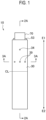
- Fig. 1 is a side view of the flavor inhaler 10 according to the first embodiment.
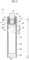
- Fig. 2 is a cross-sectional view of the flavor inhaler 10 along 2A-2A line in Fig. 1 .
- Fig. 3 is a cross-sectional view of the flavor inhaler 10 along 3A-3A line in Fig. 1 .
- the flavor inhaler 10 has a cylindrical holding member 30, an inside holding member 50, a combustion heat source 70, and a flavor source 90.
- the cylindrical holding member 30 extends from an ignition end E1 toward a non-ignition end E2.
- the ignition end E1 is an end on a side provided with the combustion heat source 70.
- Non-ignition end E2 is an end on a side provided with a suction port 40.
- the suction port 40 is positioned where a user holds in the mouth for sucking a flavor.
- the cylindrical holding member 30 may have, for example, a cylindrical shape or a rectangular cylindrical shape.
- An opening on the ignition end E1 side of the cylindrical holding member 30 is preferably closed.
- at least the inside holding member 50 and the combustion heat source 70 close the opening on the ignition end E1 side of the cylindrical holding member 30.
- the flavor inhaler 10 is preferably configured such that gas does not enter into the cylindrical holding member 30 from the opening on the ignition end E1 side of the cylindrical holding member 30.
- the inside holding member 50 is provided in the cylindrical holding member 30. However, a part of the inside holding member 50 may extend outside of the cylindrical holding member 30.
- the inside holding member 50 retains at least a part of the combustion heat source 70 and at least a part of the flavor source 90.
- the inside holding member 50 has the first side wall 51 in a cylindrical shape and an introduction port 55.
- the first side wall 51 surrounds at least a part of the flavor source 90 and at least a part of the combustion heat source 70.
- the first side wall 51 may surround at least a part of the flavor source 90 without surrounding the combustion heat source 70.
- the introduction port 55 is provided so as to introduce air to the flavor source 90 in the first side wall 51.
- the introduction port 55 may be formed from a hole formed on the first side wall 51.
- the combustion heat source 70 is provided on the ignition end E1 side of the cylindrical holding member 30.
- the combustion heat source 70 is composed from a combustible material.
- the combustible material is, for example, a mixture including a carbon material, an incombustible additive, a binder (an organic binder or an inorganic binder), and water.
- the carbon material it is preferable to use a material from which volatile impurities have been removed by a heat treatment or the like.
- the combustion heat source 70 preferably includes a carbonaceous material in a range of 30 wt. % to 70 wt. %, more preferably includes the carbonaceous material in a range of 35 wt. % to 45 wt. %.
- the combustion heat source 70 is designed such that a part on the ignition end E1 side is burned, but an end part on a non-ignition end E2 side is not burned. Namely, the end part on the non-ignition end E2 side of the combustion heat source 70 forms a non-combustion part, while other part of the combustion heat source 70 forms a combustion part.
- the flavor source 90 is provided inside the cylindrical holding member 30, on the non-ignition end E2 side from the combustion heat source 70.
- the flavor source 90 may be adjacent to the combustion heat source 70.
- the flavor source 90 is configured to generate flavor without combusting. To be more precise, the flavor source 90 generates flavor by heating with the combustion heat source 70.
- the flavor source 90 for example, a tobacco material can be used.
- the flavor source 90 may include general cut tobacco that is used for cigarettes (paper rolled tobacco), and may include granular tobacco that is used for snuff tobacco.
- the flavor source 90 may include glycerin and/or propylene glycol, in addition to the tobacco material.
- the flavor source 90 may include a flavoring agent.
- the cylindrical holding member 30 has a second side wall 32 having a cylindrical shape to surround the first side wall 51 of the inside holding member 50.
- the second side wall 32 may extend long from the ignition end E1 side toward the non-ignition end E2 side.
- the second side wall 32 may include, for example, a paper tube formed by deforming a rectangular cardboard into a cylindrical shape.
- At least the first side wall 51 of the inside holding member 50 may be formed by a thermal conductor. Additionally, it is preferable that the inside holding member 50 is integrally formed by the thermal conductor. Heat conductivity of this thermal conductor at normal temperature is preferably equal to or more than 10 W/(m ⁇ K) in a direction along the ignition end E1 to the non-ignition end E2.
- the thermal conductor for example, stainless steel can be used.
- the stainless steel for example, SUS430 may be used.
- a thickness of the first side wall 51 of the inside holding member 50 is preferably 0.1 mm or less.
- the second side wall 32 of the cylindrical holding member 30 may include a first thermal conductor 33 facing the inside holding member 50.
- the first thermal conductor 33 is arranged so as to cover at least a part of at least the first side wall 51 of the inside holding member 50.
- the first thermal conductor 33 does not need to be directly in contact with the combustion heat source 70.
- the first thermal conductor 33 promotes the heat conduction from the combustion heat source 70 to the flavor source 90.
- the first thermal conductor 33 preferably extends to the non-ignition end E2 side from an end face on the non-ignition end E2 side of the inside holding member 50.
- the first thermal conductor 33 is preferably formed from a metal material excellent in heat conductivity. Heat conductivity of the first thermal conductor 33 is preferably higher than heat conductivity of the first side wall 51.
- the first thermal conductor 33 is formed from aluminum.
- the second side wall 32 of the cylindrical holding member 30 has a through-hole 34 that is fluidly coupled to external air.
- the through-hole 34 may be provided on the ignition end E1 side from an end part on the non-ignition end E2 side of the flavor source 90.
- a flow-path forming member 60 is provided.
- the flow-path forming member 60 defines a first flow path 36 inside the cylindrical holding member 30, for allowing external air to flow to the flavor source 90.
- the flow-path forming member 60 may also be formed from a member that is separate from the first side wall 51 and the second side wall 32.
- the flow-path forming member 60 may also be formed from a member that is integrally formed on the first side wall 51 or the second side wall 32.
- the first flow path 36 connects the through-hole 34 of the second side wall 32 and the introduction port 55 of the inside holding member 50, and passes between the first side wall 51 and the second side wall 32.
- the inside holding member 50 may also have a thermal conductor (not shown) provided on an outer surface of the first side wall 51.
- This thermal conductor may be arranged so as to cover at least a part of at least the first side wall 51 of the inside holding member 50, as with the first thermal conductor 33.
- This thermal conductor promotes heat conduction from the combustion heat source 70 to the flavor source 90.
- This thermal conductor is preferably formed from a metal material excellent in heat conductivity, for example, formed from aluminum.
- the first thermal conductor 33 does not need to be provided.
- the flow-path forming member 60 may be provided between the second side wall 32 and the thermal conductor on the outer surface of the first side wall 51.
- a second flow path 38 for allowing flavor generated at the flavor source 90 to flow to the suction port 40.
- the second flow path 38 connects the flavor source 90 and the suction port 40 where the flavor generated at the flavor source 90 is sucked.
- the introduction port 55 of the inside holding member 50 may be provided on the ignition end E1 side from the through-hole 34 of the cylindrical holding member 30.
- the first flow path 36 is preferably provided only on the ignition end E1 side from the end part on the non-ignition end E2 side of the flavor source 90.
- the cylindrical holding member 30 has a hole 39 (hereinafter referred to as a "ventilation hole”) that allows external air to directly flow into the second flow path 38.
- ventilation hole a hole 39 that allows external air to directly flow into the second flow path 38.
- directly flow means that external air flows into the second flow path 38 without passing the flavor source 90.
- the ventilation hole 39 may be formed such that gas flows in a crossing direction to an extending direction of the second flow path 38 (arrow F4 in Fig. 2 ).
- the ventilation hole 39 may be formed such that gas flows in toward a center axis of the second flow path 38, along a direction substantially orthogonal to the extending direction of the second flow path 38.
- a plurality of the ventilation holes 39 are provided on a circumferential direction of the cylindrical holding member 30 at intervals. In this case, the intervals between the ventilation holes 39 may be constant.
- the ventilation hole 39 may be provided on an opposite side to the suction port 40, with respect to a center CL of the cylindrical holding member 30 in the extending direction of the second flow path 38.
- the ventilation hole 39 is preferably provided between the first thermal conductor 33 and a cooling layer 80.
- any one of the plurality of ventilation holes 39 is preferably arranged at a position not opposed to another one among the plurality of ventilation holes 39, and is more preferably arranged at a position displaced from a straight line connecting another one among the plurality of ventilation holes 39 and a center axis CA of the cylindrical holding member 30 (see Fig. 3 ).
- each of the ventilation holes 39 is not arranged on an opposite side to each of the ventilation holes 39 across the center axis CA of the cylindrical holding member 30.
- the plurality of ventilation holes 39 are preferably arranged at same positions to each other in a direction along the center axis CA of the cylindrical holding member 30.
- the plurality of ventilation holes 39 may also be arranged to be displaced to each other in a direction along the center axis CA of the cylindrical holding member 30.
- the cooling layer 80 is a layer that cools flavor generated at the flavor source 90.
- the cooling layer 80 is provided on an inner surface of the cylindrical holding member 30 to face the second flow path 38.
- the cooling layer 80 preferably surrounds the second flow path 38, in at least a part of section of the second flow path 38.
- the cooling layer 80 is preferably provided only downstream of the flavor source 90.
- the cooling layer 80 preferably has a thickness not to remarkably increase a fluid resistance of the second flow path 38. Depending on a diameter of the second flow path 38, the thickness of the cooling layer 80 is, for example, preferably 5 ⁇ m or more to 500 ⁇ m or less.
- a ratio of a cross-sectional area of the cooling layer 80 with respect to a cross-sectional area inside an inner wall of the cylindrical holding member 30 is preferably 0.2% or more to 45% or less, more preferably 0.5% or more to 5% or less.
- an outer diameter of the cylindrical holding member 30 may be 5 mm to 8 mm
- the thickness of the cylindrical holding member 30 may be 0.15 mm to 0.5 mm
- the thickness of the cooling layer 80 may be 0.05 mm to 0.5 mm.
- the cooling layer 80 is provided only downstream of the ventilation holes 39. In other words, the cooling layer 80 does not reach the upstream side from the ventilation holes 39. Alternatively, a part of the cooling layer 80 may reach the upstream side of the ventilation holes 39. Namely, only at least a part of the cooling layer 80 needs to be provided downstream of the ventilation holes 39.
- the cooling layer 80 preferably has a length equal to or longer than a half length of the second flow path 38 in the extending direction of the second flow path 38.
- the cooling layer 80 is preferably separated from the first thermal conductor 33 that composes the cylindrical holding member 30.
- the cooling layer 80 preferably defines a single channel to be passed with the flavor, in the cylindrical holding member 30. More preferably, inside of the cooling layer 80 is hollow.
- inside of the cooling layer 80 is hollow.
- “inside of the cooling layer 80 is hollow” means that any member is not present inside the cooling layer 80, other than a filter 42 provided to the suction port 40. In this case, a volume of a cavity portion in the second flow path 38 can be larger.
- the cooling layer 80 defines the single channel in the cylindrical holding member 30, and inside of the cooling layer 80 is hollow.
- inside of the cooling layer 80 is hollow.
- inside the cooling layer 80 may be provided with any member to an extent not to significantly increase a flow-path resistance of the second flow path 38.
- a cylindrical member may be provided along the center axis of the second flow path. This cylindrical member may also be provided with another cooling layer on its outer peripheral surface.
- the cooling layer 80 may include a second thermal conductor.
- the second thermal conductor may be metal.
- the cooling layer 80 may be formed from a metal pipe.
- the cooling layer 80 may be formed from a metal-laminated paper including a paper, and a metal layer that is laminated to the paper.
- the metal described above for example, aluminum can be used.
- the cooling layer 80 may also be a layer including polylactic acid (PLA).
- the cooling layer 80 may be formed from a same material as that of the first thermal conductor 33 that composes the cylindrical holding member 30.
- the cooling layer 80 may have a plurality of projections and depressions for increasing a surface area of the cooling layer 80.
- projections and depressions can be formed, for example, by crepe processing of a surface of the cooling layer 80. These projections and depressions allow an increase in a heat-exchange-surface area of the cooling layer 80, without making the cross-sectional area of the second flow path 38 too small.
- a flavor inhaler 10 has a cooling layer 80 provided only downstream of a flavor source 90, and the cooling layer 80 is provided on an inner surface of the cylindrical holding member 30 and facing a second flow path 38. Since the cooling layer 80 facing the second flow path 38 is provided on the inner surface of the cylindrical holding member 30, inside of the cylindrical holding member 30 does not need to be filled with a cooling element. If inside of the cylindrical holding member 30 is filled the cooling element, a ventilation resistance is increased, complicating a design of the ventilation resistance. In this embodiment, inside of the cylindrical holding member 30 does not need to be filled with the cooling element, achieving an easy design of the ventilation resistance.
- a cylindrical holding member 30 has a ventilation hole 39 that allows external air to flow into a second flow path 38, and at least a part of a cooling layer 80 is provided downstream of the ventilation hole 39. Gas having passed the flavor source 90 is cooled by external air flowing in from the ventilation hole 39, and is passed to the second flow path 38 to which the cooling layer 80 faces. This enables an increase in cooling efficiency of the gas flowing in the second flow path 38 passing through the flavor source 90.
- a ventilation hole 39 is formed such that external air flows into a second flow path 38 in a crossing direction to an extending direction of the second flow path 38. It has been found that a cooling layer 80 and an inflow of external air from the ventilation hole 39 cause synergistic improvement of cooling effect. This may be because a gas flow flowing toward a non-ignition end E2 in the second flow path 38 (arrow F3 in Fig. 3 ) is disturbed by external air flowing in from the ventilation hole 39 (arrow F4 in Fig. 3 ) to cause a turbulent flow, allowing the gas flow having passed the flavor source to easily come into contact with the cooling layer 80.
- a ventilation hole 39 is provided on an opposite side to a suction port 40, with respect to a center CL of a cylindrical holding member 30 in an extending direction of a second flow path 38. Longer length of the second flow path 38 on a downstream side of the ventilation hole 39 allows increased cooling effect of gas having passed the flavor source 90. Moreover, the ventilation hole 39 is relatively far away from the suction port 40, preventing possibility that a user closes the ventilation hole 39 with a finger during a puff action.
- a plurality of ventilation holes 39 are provided on a circumferential direction of a cylindrical holding member 30 at intervals. This enables uniform cooling of gas in a second flow path 38 in a circumferential direction of the second flow path 38.
- a cooling layer 80 is separated from a first thermal conductor 33. This can prevent a direct flow of heat generated at a combustion heat source 70, into the cooling layer 80. This results in enabling prevention of a reduction in cooling effect of the cooling layer 80. Moreover, the heat generated at the combustion heat source 70 is effectively transmitted to a flavor source 90.
- a ventilation hole 39 is provided between a first thermal conductor 33 and a cooling layer 80. Namely, the ventilation hole 39 is provided where the first thermal conductor 33 or the cooling layer 80 is not present. This provides an advantage that the ventilation hole 39 can be easily formed to a cylindrical holding member 30.
- a cooling layer 80 is formed from a same material as that of a first thermal conductor 33. This allows the first thermal conductor 33 and the cooling layer 80 to be formed in a same process, enabling easy production of a flavor inhaler 10.
- a cooling layer 80 defines a single channel to be passed with flavor.
- inside of a cooling layer 80 is hollow. This allows a ventilation resistance to be maintained relatively low, compared with an aspect in which inside of a cylindrical holding member 30 is filled with a cooling element curled so as to form a plurality of channels.
- a cooling layer 80 has a length equal to or longer than a half length of a second flow path 38 in an extending direction of the second flow path 38. Since the cooling layer 80 extends thus relatively long, cooling efficiency of gas in the second flow path 38 can be promoted.
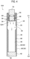
- a flavor inhaler 10A according to a second embodiment is described below with reference to Fig. 4 .
- the same reference numerals are given to the same configurations as those of the first embodiment. Differences from the first embodiment are mainly described below.
- a cylindrical holding member 30 has a plurality of layers, at least at a section provided with a second flow path 38.
- the cylindrical holding member 30 may have an outer-wall portion 85, and an inner-wall portion 84 provided inside the outer-wall portion.
- the inner-wall portion 84 may be formed from a sheet attached to an inner surface of the outer-wall portion 85.
- the inner-wall portion 84 may also be formed from a pipe member inserted into the outer-wall portion 85.
- the cooling layer 80 is provided on an inner surface of the cylindrical holding member 30, namely, on an inner surface of the inner-wall portion 84.
- the cooling layer 80 may also be formed on the inner surface of the cylindrical holding member 30 that has a plurality of layers.
- a thickness of the cylindrical holding member 30 and a thickness of the cooling layer 80 are preferably designed so as not to make a cross-sectional area of the second flow path 38 too small.
- the cross-sectional area of the second flow path 38 in a cross section vertical to a center axis CA of the cylindrical holding member 30 is preferably 5 mm 2 or more to 50 mm 2 or less, more preferably 15 mm 2 or more to 35 mm 2 or less.
- an outer diameter of the cylindrical holding member 30 may be 5 mm to 8 mm
- the thickness of the cylindrical holding member 30 may be 0.15 mm to 0.5 mm
- the thickness of the cooling layer 80 may be 0.05 mm to 0.5 mm.
- a flavor inhaler including a cooling layer enabling an easy design of a ventilation resistance can be provided.
Landscapes
- Health & Medical Sciences (AREA)
- Engineering & Computer Science (AREA)
- General Health & Medical Sciences (AREA)
- Public Health (AREA)
- Anesthesiology (AREA)
- Biomedical Technology (AREA)
- Heart & Thoracic Surgery (AREA)
- Hematology (AREA)
- Life Sciences & Earth Sciences (AREA)
- Animal Behavior & Ethology (AREA)
- Veterinary Medicine (AREA)
- Chemical & Material Sciences (AREA)
- Chemical Kinetics & Catalysis (AREA)
- General Chemical & Material Sciences (AREA)
- Pulmonology (AREA)
- Bioinformatics & Cheminformatics (AREA)
- Cigarettes, Filters, And Manufacturing Of Filters (AREA)
- Disinfection, Sterilisation Or Deodorisation Of Air (AREA)
- Thermotherapy And Cooling Therapy Devices (AREA)
- Manufacture Of Tobacco Products (AREA)
- Medicinal Preparation (AREA)
- Cold Air Circulating Systems And Constructional Details In Refrigerators (AREA)
Claims (15)
- Geschmacksinhalator (10), umfassend:eine Geschmacksquelle (90), die so konfiguriert ist, dass sie einen Geschmack ohne Verbrennung erzeugt;ein zylindrisches Halteelement (30), das zumindest die Geschmacksquelle (90) im Inneren einschließt; undeinen Strömungspfad (36, 38), der in dem zylindrischen Halteelement (30) bereitgestellt ist und sich von der Geschmacksquelle (90) in Richtung einer Ansaugöffnung (40) zum Ansaugen des Geschmacks erstreckt;wobei die Ansaugöffnung (40) einen Filter (42) umfasst; undwobei das zylindrische Halteelement (30) ein oder mehrere Bohrungen (39) aufweist, die so angeordnet sind, dass Außenluft in den Strömungspfad (36, 38) strömt, ohne die Geschmacksquelle (90) zu passieren, gekennzeichnet durch eine Kühlschicht (80), die nur stromabwärts von der Geschmacksquelle (90) bereitgestellt ist, wobei die Kühlschicht (80) an einer Innenfläche des zylindrischen Halteelements (30) bereitgestellt ist und dem Strömungspfad (36, 38) zugewandt ist, und wobei das Innere der Kühlschicht (80) hohl ist.
- Geschmacksinhalator (10) nach Anspruch 1, wobei das eine oder die mehreren Bohrungen (39) so gebildet sind, dass Außenluft in den Strömungspfad (36, 38) in Richtung einer Mittelachse (CA) des zylindrischen Halteelements (30) entlang einer Richtung strömt, die im Wesentlichen orthogonal zu einer beabsichtigten Strömungsrichtung der Luft ist, die in dem Strömungspfad (36, 38) von der Geschmacksquelle (90) in Richtung der Ansaugöffnung (40) strömt.
- Geschmacksinhalator (10) nach einem vorstehenden Anspruch, wobei eine Vielzahl des einen oder der mehreren Bohrungen (39) in einer Richtung um den Umfang des zylindrischen Halteelements (30) in Abständen bereitgestellt ist.
- Geschmacksinhalator (10) nach Anspruch 3, wobei die Abstände zwischen den Bohrungen (39) konstant sind.
- Geschmacksinhalator (10) nach einem vorstehenden Anspruch, wobei zumindest ein Teil der Kühlschicht (80) stromabwärts von den Bohrungen (39) bereitgestellt ist.
- Geschmacksinhalator (10) nach einem vorstehenden Anspruch, wobei die Kühlschicht (80) eine Dicke von 0,005 mm oder mehr bis 0,5 mm oder weniger, bevorzugt von 0,05 mm oder mehr bis 0,5 mm oder weniger aufweist.
- Geschmacksinhalator (10) nach einem vorstehenden Anspruch, wobei in einem Querschnitt senkrecht zu einer Mittelachse (CA) des zylindrischen Halteelements (30) ein Verhältnis einer Querschnittsfläche der Kühlschicht (80) zur Querschnittsfläche innerhalb einer inneren Wand des zylindrischen Halteelements (30) 0,2 % oder mehr bis 45 % oder weniger, bevorzugt 0,5 % oder mehr bis 5 % oder weniger beträgt.
- Geschmacksinhalator (10) nach einem vorstehenden Anspruch, wobei in einem Querschnitt senkrecht zu einer Mittelachse (CA) des zylindrischen Halteelements (30) ein äußerer Durchmesser des zylindrischen Halteelements (30) zwischen 5 mm und 8 mm beträgt, die Dicke des zylindrischen Halteelements (30) zwischen 0,15 mm und 0,5 mm beträgt und die Dicke der Kühlschicht (80) zwischen 0,05 mm und 0,5 mm beträgt.
- Geschmacksinhalator (10) nach einem vorstehenden Anspruch, wobei die Kühlschicht (80) einen einzigen Kanal zum Durchlassen des Geschmacks definiert.
- Geschmacksinhalator (10) nach einem vorstehenden Anspruch, wobei die Geschmacksquelle (90) ein Tabakmaterial einschließt.
- Geschmacksinhalator (10) nach Anspruch 10, wobei die Geschmacksquelle (90) weiter Glycerin und/oder Propylenglykol einschließt.
- Geschmacksinhalator (10) nach Anspruch 10 oder 11, wobei die Geschmacksquelle (90) weiter einen Geschmacksstoff einschließt.
- Geschmacksinhalator (10) nach einem vorstehenden Anspruch, wobei die Kühlschicht (80) eine Länge aufweist, die gleich oder länger ist als eine halbe Länge des Strömungspfads (36, 38) in der Richtung, in der sich der Strömungspfad (36, 38) erstreckt.
- Geschmacksinhalator (10) nach einem vorstehenden Anspruch, wobei die Kühlschicht (80) eine Schicht ist, die an der Geschmacksquelle (90) erzeugten Geschmack kühlt.
- Geschmacksinhalator (10) nach einem vorstehenden Anspruch, wobei die Kühlschicht (80) aus einem Metallrohr, einem metallbeschichteten Papier, das ein Papier und eine auf das Papier aufgebrachte Metallschicht einschließt, Aluminium oder einer Schicht, die Polymilchsäure (PLA) einschließt, gebildet ist.
Priority Applications (4)
| Application Number | Priority Date | Filing Date | Title |
|---|---|---|---|
| EP24176266.5A EP4397341B1 (de) | 2015-04-06 | 2015-04-06 | Geschmacksinhalator |
| EP25187539.9A EP4628127A3 (de) | 2015-04-06 | 2015-04-06 | Geschmacksinhalator |
| ES24176266T ES3042843T3 (en) | 2015-04-06 | 2015-04-06 | Flavor inhaler |
| PL24176266.5T PL4397341T3 (pl) | 2015-04-06 | 2015-04-06 | Inhalator substancji smakowo-zapachowej |
Applications Claiming Priority (4)
| Application Number | Priority Date | Filing Date | Title |
|---|---|---|---|
| EP22159382.5A EP4026447B1 (de) | 2015-04-06 | 2015-04-06 | Geschmacksinhalator |
| EP24176266.5A EP4397341B1 (de) | 2015-04-06 | 2015-04-06 | Geschmacksinhalator |
| PCT/JP2015/060786 WO2016162934A1 (ja) | 2015-04-06 | 2015-04-06 | 香味吸引器 |
| EP15888428.8A EP3284354B1 (de) | 2015-04-06 | 2015-04-06 | Geschmacksinhalator |
Related Parent Applications (3)
| Application Number | Title | Priority Date | Filing Date |
|---|---|---|---|
| EP15888428.8A Division EP3284354B1 (de) | 2015-04-06 | 2015-04-06 | Geschmacksinhalator |
| EP22159382.5A Division-Into EP4026447B1 (de) | 2015-04-06 | 2015-04-06 | Geschmacksinhalator |
| EP22159382.5A Division EP4026447B1 (de) | 2015-04-06 | 2015-04-06 | Geschmacksinhalator |
Related Child Applications (1)
| Application Number | Title | Priority Date | Filing Date |
|---|---|---|---|
| EP25187539.9A Division EP4628127A3 (de) | 2015-04-06 | 2015-04-06 | Geschmacksinhalator |
Publications (4)
| Publication Number | Publication Date |
|---|---|
| EP4397341A2 EP4397341A2 (de) | 2024-07-10 |
| EP4397341A3 EP4397341A3 (de) | 2024-09-04 |
| EP4397341B1 true EP4397341B1 (de) | 2025-07-09 |
| EP4397341C0 EP4397341C0 (de) | 2025-07-09 |
Family
ID=57072423
Family Applications (4)
| Application Number | Title | Priority Date | Filing Date |
|---|---|---|---|
| EP24176266.5A Active EP4397341B1 (de) | 2015-04-06 | 2015-04-06 | Geschmacksinhalator |
| EP25187539.9A Pending EP4628127A3 (de) | 2015-04-06 | 2015-04-06 | Geschmacksinhalator |
| EP15888428.8A Active EP3284354B1 (de) | 2015-04-06 | 2015-04-06 | Geschmacksinhalator |
| EP22159382.5A Active EP4026447B1 (de) | 2015-04-06 | 2015-04-06 | Geschmacksinhalator |
Family Applications After (3)
| Application Number | Title | Priority Date | Filing Date |
|---|---|---|---|
| EP25187539.9A Pending EP4628127A3 (de) | 2015-04-06 | 2015-04-06 | Geschmacksinhalator |
| EP15888428.8A Active EP3284354B1 (de) | 2015-04-06 | 2015-04-06 | Geschmacksinhalator |
| EP22159382.5A Active EP4026447B1 (de) | 2015-04-06 | 2015-04-06 | Geschmacksinhalator |
Country Status (11)
| Country | Link |
|---|---|
| US (1) | US11013868B2 (de) |
| EP (4) | EP4397341B1 (de) |
| JP (1) | JP6379287B2 (de) |
| KR (5) | KR20190086579A (de) |
| CN (1) | CN107404946B (de) |
| EA (1) | EA039036B1 (de) |
| ES (2) | ES3042843T3 (de) |
| HU (1) | HUE069791T2 (de) |
| PL (2) | PL4397341T3 (de) |
| TW (1) | TWI597020B (de) |
| WO (1) | WO2016162934A1 (de) |
Families Citing this family (30)
| Publication number | Priority date | Publication date | Assignee | Title |
|---|---|---|---|---|
| JP6282379B2 (ja) * | 2015-04-06 | 2018-02-21 | 日本たばこ産業株式会社 | 香味吸引器及び内側保持部材 |
| US10314334B2 (en) | 2015-12-10 | 2019-06-11 | R.J. Reynolds Tobacco Company | Smoking article |
| US11744296B2 (en) | 2015-12-10 | 2023-09-05 | R. J. Reynolds Tobacco Company | Smoking article |
| US11723399B2 (en) | 2018-07-13 | 2023-08-15 | R.J. Reynolds Tobacco Company | Smoking article with detachable cartridge |
| CN112839531A (zh) * | 2018-10-05 | 2021-05-25 | 日本烟草产业株式会社 | 吸烟物品的制造方法 |
| WO2020084758A1 (ja) * | 2018-10-26 | 2020-04-30 | 日本たばこ産業株式会社 | 加熱アセンブリおよびこれを備える香味吸引器 |
| KR102742303B1 (ko) * | 2018-11-14 | 2024-12-16 | 니뽄 다바코 산교 가부시키가이샤 | 냉각 세그먼트 및 그 제조 방법, 비연소 가열 흡연 물품, 그리고 비연소 가열 흡연 시스템 |
| CN113645858B (zh) * | 2019-03-28 | 2023-08-25 | 日本烟草产业株式会社 | 加热式香烟、加热式香烟制品、加热式香烟中的烟杆的制造方法以及制造装置 |
| US12075819B2 (en) | 2019-07-18 | 2024-09-03 | R.J. Reynolds Tobacco Company | Aerosol delivery device with consumable cartridge |
| US12022859B2 (en) | 2019-07-18 | 2024-07-02 | R.J. Reynolds Tobacco Company | Thermal energy absorbers for tobacco heating products |
| US11395510B2 (en) | 2019-07-19 | 2022-07-26 | R.J. Reynolds Tobacco Company | Aerosol delivery device with rotatable enclosure for cartridge |
| US11330838B2 (en) | 2019-07-19 | 2022-05-17 | R. J. Reynolds Tobacco Company | Holder for aerosol delivery device with detachable cartridge |
| US12232542B2 (en) | 2019-07-19 | 2025-02-25 | R.J. Reynolds Tobacco Company | Aerosol delivery device with sliding sleeve |
| US12082607B2 (en) | 2019-07-19 | 2024-09-10 | R.J. Reynolds Tobacco Company | Aerosol delivery device with clamshell holder for cartridge |
| MX2022010881A (es) | 2020-03-12 | 2022-10-07 | Philip Morris Products Sa | Articulo generador de aerosol que tiene una pluralidad de zonas de entrada de aire. |
| US12484610B2 (en) | 2020-04-16 | 2025-12-02 | R.J. Reynolds Tobacco Company | Aerosol delivery device including a segregated substrate |
| US11589616B2 (en) | 2020-04-29 | 2023-02-28 | R.J. Reynolds Tobacco Company | Aerosol delivery device with sliding and axially rotating locking mechanism |
| US11439185B2 (en) | 2020-04-29 | 2022-09-13 | R. J. Reynolds Tobacco Company | Aerosol delivery device with sliding and transversely rotating locking mechanism |
| US12426634B2 (en) | 2021-04-02 | 2025-09-30 | R. J. Reynolds Tobacco Company | Aerosol delivery device with integrated lighter |
| US12426633B2 (en) | 2021-04-02 | 2025-09-30 | R. J. Reynolds Tobacco Company | Aerosol delivery device with integrated inductive heater |
| US12433340B2 (en) | 2021-04-02 | 2025-10-07 | R. J. Reynolds Tobacco Company | Aerosol delivery device consumable unit |
| US11825872B2 (en) | 2021-04-02 | 2023-11-28 | R.J. Reynolds Tobacco Company | Aerosol delivery device with protective sleeve |
| US12250969B2 (en) | 2021-04-02 | 2025-03-18 | R. J. Reynolds Tobacco Company | Aerosol delivery device with modular lighter |
| US12426637B2 (en) | 2021-08-17 | 2025-09-30 | Rai Strategic Holdings, Inc. | Inductively heated aerosol delivery device consumable |
| JP7457177B2 (ja) * | 2021-12-09 | 2024-03-27 | 日本たばこ産業株式会社 | 加熱式たばこ |
| KR102692373B1 (ko) * | 2021-12-23 | 2024-08-07 | 주식회사 케이티앤지 | 흡연 물품용 가연성 열원 조성물 및 이를 포함하는 흡연 물품 |
| KR102805612B1 (ko) * | 2021-12-23 | 2025-05-13 | 주식회사 케이티앤지 | 흡연 물품용 가연성 열원 및 이를 포함하는 흡연 물품 |
| US12329199B2 (en) | 2022-08-30 | 2025-06-17 | R.J. Reynolds Tobaco Company | Aerosol delivery device with improved mouthpieces |
| US12357024B2 (en) | 2022-08-30 | 2025-07-15 | R. J. Reynolds Tobacco Company | Aerosol delivery device with static ignitor contacts |
| US12471639B2 (en) | 2022-12-14 | 2025-11-18 | R.J. Reynolds Tobacco Company | Aerosol delivery device with improved cartridge loading |
Family Cites Families (22)
| Publication number | Priority date | Publication date | Assignee | Title |
|---|---|---|---|---|
| US5159940A (en) * | 1988-07-22 | 1992-11-03 | Philip Morris Incorporated | Smoking article |
| US6089857A (en) * | 1996-06-21 | 2000-07-18 | Japan Tobacco, Inc. | Heater for generating flavor and flavor generation appliance |
| JP3327826B2 (ja) * | 1997-12-05 | 2002-09-24 | 日本たばこ産業株式会社 | 香味生成物品及び香味生成器具 |
| CA2271432A1 (en) | 1999-05-11 | 2000-11-11 | Han Jo Lee | Filter cigarettes with air chambers |
| AU2002357599A1 (en) * | 2001-12-28 | 2003-07-24 | Japan Tobacco Inc. | Smoking implement |
| US6810883B2 (en) * | 2002-11-08 | 2004-11-02 | Philip Morris Usa Inc. | Electrically heated cigarette smoking system with internal manifolding for puff detection |
| EP1848483B1 (de) * | 2005-02-02 | 2014-03-12 | Oglesby&Butler Research&Development Limited | Vorrichtung zum verdunsten einer verdunstbaren substanz |
| US20080047571A1 (en) | 2006-07-12 | 2008-02-28 | Philip Morris Usa Inc. | Smoking article with plate impactor |
| KR101588906B1 (ko) * | 2007-08-10 | 2016-01-28 | 필립모리스 프로덕츠 에스.에이. | 증류식 흡연 물품 |
| US8617263B2 (en) * | 2008-09-18 | 2013-12-31 | R. J. Reynolds Tobacco Company | Method for preparing fuel element for smoking article |
| EP2893822B2 (de) * | 2010-03-26 | 2022-08-03 | Japan Tobacco Inc. | Rauchartikel |
| GB201104788D0 (en) | 2011-03-22 | 2011-05-04 | British American Tobacco Co | Smoking article |
| JP5668674B2 (ja) | 2011-12-07 | 2015-02-12 | 株式会社デンソー | 電子装置 |
| JP2013120565A (ja) | 2011-12-08 | 2013-06-17 | Sharp Corp | 情報処理装置、携帯端末 |
| EP2787848B1 (de) * | 2011-12-08 | 2018-08-22 | Philip Morris Products S.a.s. | Aerosolerzeugungsvorrichtung mit luftstromdüsen |
| EP2625975A1 (de) * | 2012-02-13 | 2013-08-14 | Philip Morris Products S.A. | Aerosolerzeugender Artikel mit Aerosolkühlelement |
| TWI590769B (zh) * | 2012-02-13 | 2017-07-11 | 菲利浦莫里斯製品股份有限公司 | 包含雙導熱元件之吸煙製品及調整吸煙製品一口接一口抽吸的氣溶膠遞送量的方法 |
| AR095307A1 (es) * | 2013-03-15 | 2015-10-07 | Philip Morris Products Sa | Artículo para fumar con un elemento conductor del flujo de aire que comprende un agente modificador del aerosol |
| US9877511B2 (en) * | 2013-07-24 | 2018-01-30 | Altria Client Services Llc | Electronic smoking article |
| UA118033C2 (uk) * | 2013-08-13 | 2018-11-12 | Філіп Морріс Продактс С.А. | Курильний виріб, що містить суцільне горюче джерело теплоти |
| UA121375C2 (uk) * | 2013-12-05 | 2020-05-25 | Філіп Морріс Продактс С.А. | Виріб, що генерує аерозоль, зі шляхом низького опору повітряному потоку |
| GB201413028D0 (en) * | 2014-02-28 | 2014-09-03 | Beyond Twenty Ltd | Beyond 5 |
-
2015
- 2015-04-06 EP EP24176266.5A patent/EP4397341B1/de active Active
- 2015-04-06 CN CN201580078361.0A patent/CN107404946B/zh active Active
- 2015-04-06 KR KR1020197020011A patent/KR20190086579A/ko not_active Abandoned
- 2015-04-06 WO PCT/JP2015/060786 patent/WO2016162934A1/ja not_active Ceased
- 2015-04-06 EP EP25187539.9A patent/EP4628127A3/de active Pending
- 2015-04-06 ES ES24176266T patent/ES3042843T3/es active Active
- 2015-04-06 KR KR1020197020013A patent/KR102229429B1/ko active Active
- 2015-04-06 JP JP2017510819A patent/JP6379287B2/ja active Active
- 2015-04-06 EP EP15888428.8A patent/EP3284354B1/de active Active
- 2015-04-06 ES ES22159382T patent/ES3004869T3/es active Active
- 2015-04-06 EP EP22159382.5A patent/EP4026447B1/de active Active
- 2015-04-06 KR KR1020197020012A patent/KR102242830B1/ko not_active Expired - Fee Related
- 2015-04-06 HU HUE22159382A patent/HUE069791T2/hu unknown
- 2015-04-06 PL PL24176266.5T patent/PL4397341T3/pl unknown
- 2015-04-06 EA EA201792223A patent/EA039036B1/ru unknown
- 2015-04-06 PL PL22159382.5T patent/PL4026447T3/pl unknown
- 2015-04-06 KR KR1020177028581A patent/KR102000864B1/ko active Active
- 2015-04-06 KR KR1020197020014A patent/KR20190086582A/ko not_active Withdrawn
- 2015-12-24 TW TW104143533A patent/TWI597020B/zh active
-
2017
- 2017-09-28 US US15/718,211 patent/US11013868B2/en active Active
Also Published As
Similar Documents
| Publication | Publication Date | Title |
|---|---|---|
| EP4397341B1 (de) | Geschmacksinhalator | |
| US10426194B2 (en) | Flavor inhaler and inside holding member | |
| US10588345B2 (en) | Flavor inhaler, inside holding member, production method for flavor inhaler, and production method for inside holding member | |
| KR20180092998A (ko) | 환기 영역을 갖는 에어로졸 발생 물품 | |
| EA045533B1 (ru) | Ингалятор аромата | |
| HK1245594B (zh) | 香味吸取器 | |
| US20240358065A1 (en) | An article for use with a non-combustible aerosol provision device | |
| EA045529B1 (ru) | Ингалятор аромата | |
| EA045474B1 (ru) | Ингалятор аромата | |
| KR20250034283A (ko) | 에어로졸 발생 시스템 | |
| HK1245595B (zh) | 香味吸取器及内侧保持部件 |
Legal Events
| Date | Code | Title | Description |
|---|---|---|---|
| PUAI | Public reference made under article 153(3) epc to a published international application that has entered the european phase |
Free format text: ORIGINAL CODE: 0009012 |
|
| STAA | Information on the status of an ep patent application or granted ep patent |
Free format text: STATUS: REQUEST FOR EXAMINATION WAS MADE |
|
| 17P | Request for examination filed |
Effective date: 20240516 |
|
| AC | Divisional application: reference to earlier application |
Ref document number: 3284354 Country of ref document: EP Kind code of ref document: P Ref document number: 4026447 Country of ref document: EP Kind code of ref document: P |
|
| AK | Designated contracting states |
Kind code of ref document: A2 Designated state(s): AL AT BE BG CH CY CZ DE DK EE ES FI FR GB GR HR HU IE IS IT LI LT LU LV MC MK MT NL NO PL PT RO RS SE SI SK SM TR |
|
| REG | Reference to a national code |
Ref country code: DE Ref legal event code: R079 Free format text: PREVIOUS MAIN CLASS: A61M0011040000 Ipc: A24F0047000000 Ref country code: DE Ref legal event code: R079 Ref document number: 602015092001 Country of ref document: DE Free format text: PREVIOUS MAIN CLASS: A61M0011040000 Ipc: A24F0047000000 |
|
| PUAL | Search report despatched |
Free format text: ORIGINAL CODE: 0009013 |
|
| STAA | Information on the status of an ep patent application or granted ep patent |
Free format text: STATUS: EXAMINATION IS IN PROGRESS |
|
| AK | Designated contracting states |
Kind code of ref document: A3 Designated state(s): AL AT BE BG CH CY CZ DE DK EE ES FI FR GB GR HR HU IE IS IT LI LT LU LV MC MK MT NL NO PL PT RO RS SE SI SK SM TR |
|
| RIC1 | Information provided on ipc code assigned before grant |
Ipc: A61M 11/04 20060101ALI20240726BHEP Ipc: A24D 1/00 20200101ALI20240726BHEP Ipc: A61M 15/06 20060101ALI20240726BHEP Ipc: A24F 47/00 20200101AFI20240726BHEP |
|
| 17Q | First examination report despatched |
Effective date: 20240813 |
|
| REG | Reference to a national code |
Ref country code: DE Ref legal event code: R079 Free format text: PREVIOUS MAIN CLASS: A24F0047000000 Ipc: A24D0001220000 Ref country code: DE Ref legal event code: R079 Ref document number: 602015092001 Country of ref document: DE Free format text: PREVIOUS MAIN CLASS: A24F0047000000 Ipc: A24D0001220000 |
|
| GRAP | Despatch of communication of intention to grant a patent |
Free format text: ORIGINAL CODE: EPIDOSNIGR1 |
|
| STAA | Information on the status of an ep patent application or granted ep patent |
Free format text: STATUS: GRANT OF PATENT IS INTENDED |
|
| RIC1 | Information provided on ipc code assigned before grant |
Ipc: A61M 11/04 20060101ALI20250120BHEP Ipc: A61M 15/06 20060101ALI20250120BHEP Ipc: A24F 47/00 20200101ALI20250120BHEP Ipc: A24D 1/00 20200101ALI20250120BHEP Ipc: A24D 1/22 20200101AFI20250120BHEP |
|
| INTG | Intention to grant announced |
Effective date: 20250203 |
|
| GRAS | Grant fee paid |
Free format text: ORIGINAL CODE: EPIDOSNIGR3 |
|
| GRAA | (expected) grant |
Free format text: ORIGINAL CODE: 0009210 |
|
| STAA | Information on the status of an ep patent application or granted ep patent |
Free format text: STATUS: THE PATENT HAS BEEN GRANTED |
|
| AC | Divisional application: reference to earlier application |
Ref document number: 3284354 Country of ref document: EP Kind code of ref document: P Ref document number: 4026447 Country of ref document: EP Kind code of ref document: P |
|
| AK | Designated contracting states |
Kind code of ref document: B1 Designated state(s): AL AT BE BG CH CY CZ DE DK EE ES FI FR GB GR HR HU IE IS IT LI LT LU LV MC MK MT NL NO PL PT RO RS SE SI SK SM TR |
|
| REG | Reference to a national code |
Ref country code: GB Ref legal event code: FG4D |
|
| REG | Reference to a national code |
Ref country code: CH Ref legal event code: EP |
|
| REG | Reference to a national code |
Ref country code: IE Ref legal event code: FG4D |
|
| REG | Reference to a national code |
Ref country code: DE Ref legal event code: R096 Ref document number: 602015092001 Country of ref document: DE |
|
| U01 | Request for unitary effect filed |
Effective date: 20250807 |
|
| U07 | Unitary effect registered |
Designated state(s): AT BE BG DE DK EE FI FR IT LT LU LV MT NL PT RO SE SI Effective date: 20250820 |
|
| REG | Reference to a national code |
Ref country code: ES Ref legal event code: FG2A Ref document number: 3042843 Country of ref document: ES Kind code of ref document: T3 Effective date: 20251124 |