EP4397284A1 - Stentvorrichtung und stenteinführungssystem - Google Patents
Stentvorrichtung und stenteinführungssystem Download PDFInfo
- Publication number
- EP4397284A1 EP4397284A1 EP21955974.7A EP21955974A EP4397284A1 EP 4397284 A1 EP4397284 A1 EP 4397284A1 EP 21955974 A EP21955974 A EP 21955974A EP 4397284 A1 EP4397284 A1 EP 4397284A1
- Authority
- EP
- European Patent Office
- Prior art keywords
- stent
- expanded
- cover
- stent device
- fixation
- Prior art date
- Legal status (The legal status is an assumption and is not a legal conclusion. Google has not performed a legal analysis and makes no representation as to the accuracy of the status listed.)
- Pending
Links
Images


Classifications
-
- A—HUMAN NECESSITIES
- A61—MEDICAL OR VETERINARY SCIENCE; HYGIENE
- A61F—FILTERS IMPLANTABLE INTO BLOOD VESSELS; PROSTHESES; DEVICES PROVIDING PATENCY TO, OR PREVENTING COLLAPSING OF, TUBULAR STRUCTURES OF THE BODY, e.g. STENTS; ORTHOPAEDIC, NURSING OR CONTRACEPTIVE DEVICES; FOMENTATION; TREATMENT OR PROTECTION OF EYES OR EARS; BANDAGES, DRESSINGS OR ABSORBENT PADS; FIRST-AID KITS
- A61F2/00—Filters implantable into blood vessels; Prostheses, i.e. artificial substitutes or replacements for parts of the body; Appliances for connecting them with the body; Devices providing patency to, or preventing collapsing of, tubular structures of the body, e.g. stents
- A61F2/02—Prostheses implantable into the body
- A61F2/04—Hollow or tubular parts of organs, e.g. bladders, tracheae, bronchi or bile ducts
- A61F2/06—Blood vessels
- A61F2/07—Stent-grafts
-
- A—HUMAN NECESSITIES
- A61—MEDICAL OR VETERINARY SCIENCE; HYGIENE
- A61F—FILTERS IMPLANTABLE INTO BLOOD VESSELS; PROSTHESES; DEVICES PROVIDING PATENCY TO, OR PREVENTING COLLAPSING OF, TUBULAR STRUCTURES OF THE BODY, e.g. STENTS; ORTHOPAEDIC, NURSING OR CONTRACEPTIVE DEVICES; FOMENTATION; TREATMENT OR PROTECTION OF EYES OR EARS; BANDAGES, DRESSINGS OR ABSORBENT PADS; FIRST-AID KITS
- A61F2/00—Filters implantable into blood vessels; Prostheses, i.e. artificial substitutes or replacements for parts of the body; Appliances for connecting them with the body; Devices providing patency to, or preventing collapsing of, tubular structures of the body, e.g. stents
- A61F2/95—Instruments specially adapted for placement or removal of stents or stent-grafts
-
- A—HUMAN NECESSITIES
- A61—MEDICAL OR VETERINARY SCIENCE; HYGIENE
- A61F—FILTERS IMPLANTABLE INTO BLOOD VESSELS; PROSTHESES; DEVICES PROVIDING PATENCY TO, OR PREVENTING COLLAPSING OF, TUBULAR STRUCTURES OF THE BODY, e.g. STENTS; ORTHOPAEDIC, NURSING OR CONTRACEPTIVE DEVICES; FOMENTATION; TREATMENT OR PROTECTION OF EYES OR EARS; BANDAGES, DRESSINGS OR ABSORBENT PADS; FIRST-AID KITS
- A61F2/00—Filters implantable into blood vessels; Prostheses, i.e. artificial substitutes or replacements for parts of the body; Appliances for connecting them with the body; Devices providing patency to, or preventing collapsing of, tubular structures of the body, e.g. stents
- A61F2/82—Devices providing patency to, or preventing collapsing of, tubular structures of the body, e.g. stents
- A61F2/86—Stents in a form characterised by the wire-like elements; Stents in the form characterised by a net-like or mesh-like structure
- A61F2/90—Stents in a form characterised by the wire-like elements; Stents in the form characterised by a net-like or mesh-like structure characterised by a net-like or mesh-like structure
-
- A—HUMAN NECESSITIES
- A61—MEDICAL OR VETERINARY SCIENCE; HYGIENE
- A61F—FILTERS IMPLANTABLE INTO BLOOD VESSELS; PROSTHESES; DEVICES PROVIDING PATENCY TO, OR PREVENTING COLLAPSING OF, TUBULAR STRUCTURES OF THE BODY, e.g. STENTS; ORTHOPAEDIC, NURSING OR CONTRACEPTIVE DEVICES; FOMENTATION; TREATMENT OR PROTECTION OF EYES OR EARS; BANDAGES, DRESSINGS OR ABSORBENT PADS; FIRST-AID KITS
- A61F2/00—Filters implantable into blood vessels; Prostheses, i.e. artificial substitutes or replacements for parts of the body; Appliances for connecting them with the body; Devices providing patency to, or preventing collapsing of, tubular structures of the body, e.g. stents
- A61F2/95—Instruments specially adapted for placement or removal of stents or stent-grafts
- A61F2/962—Instruments specially adapted for placement or removal of stents or stent-grafts having an outer sleeve
- A61F2/966—Instruments specially adapted for placement or removal of stents or stent-grafts having an outer sleeve with relative longitudinal movement between outer sleeve and prosthesis, e.g. using a push rod
-
- A—HUMAN NECESSITIES
- A61—MEDICAL OR VETERINARY SCIENCE; HYGIENE
- A61F—FILTERS IMPLANTABLE INTO BLOOD VESSELS; PROSTHESES; DEVICES PROVIDING PATENCY TO, OR PREVENTING COLLAPSING OF, TUBULAR STRUCTURES OF THE BODY, e.g. STENTS; ORTHOPAEDIC, NURSING OR CONTRACEPTIVE DEVICES; FOMENTATION; TREATMENT OR PROTECTION OF EYES OR EARS; BANDAGES, DRESSINGS OR ABSORBENT PADS; FIRST-AID KITS
- A61F2/00—Filters implantable into blood vessels; Prostheses, i.e. artificial substitutes or replacements for parts of the body; Appliances for connecting them with the body; Devices providing patency to, or preventing collapsing of, tubular structures of the body, e.g. stents
- A61F2/02—Prostheses implantable into the body
- A61F2/04—Hollow or tubular parts of organs, e.g. bladders, tracheae, bronchi or bile ducts
- A61F2/06—Blood vessels
- A61F2/07—Stent-grafts
- A61F2002/072—Encapsulated stents, e.g. wire or whole stent embedded in lining
-
- A—HUMAN NECESSITIES
- A61—MEDICAL OR VETERINARY SCIENCE; HYGIENE
- A61F—FILTERS IMPLANTABLE INTO BLOOD VESSELS; PROSTHESES; DEVICES PROVIDING PATENCY TO, OR PREVENTING COLLAPSING OF, TUBULAR STRUCTURES OF THE BODY, e.g. STENTS; ORTHOPAEDIC, NURSING OR CONTRACEPTIVE DEVICES; FOMENTATION; TREATMENT OR PROTECTION OF EYES OR EARS; BANDAGES, DRESSINGS OR ABSORBENT PADS; FIRST-AID KITS
- A61F2220/00—Fixations or connections for prostheses classified in groups A61F2/00 - A61F2/26 or A61F2/82 or A61F9/00 or A61F11/00 or subgroups thereof
- A61F2220/0008—Fixation appliances for connecting prostheses to the body
-
- A—HUMAN NECESSITIES
- A61—MEDICAL OR VETERINARY SCIENCE; HYGIENE
- A61F—FILTERS IMPLANTABLE INTO BLOOD VESSELS; PROSTHESES; DEVICES PROVIDING PATENCY TO, OR PREVENTING COLLAPSING OF, TUBULAR STRUCTURES OF THE BODY, e.g. STENTS; ORTHOPAEDIC, NURSING OR CONTRACEPTIVE DEVICES; FOMENTATION; TREATMENT OR PROTECTION OF EYES OR EARS; BANDAGES, DRESSINGS OR ABSORBENT PADS; FIRST-AID KITS
- A61F2230/00—Geometry of prostheses classified in groups A61F2/00 - A61F2/26 or A61F2/82 or A61F9/00 or A61F11/00 or subgroups thereof
- A61F2230/0063—Three-dimensional shapes
- A61F2230/0069—Three-dimensional shapes cylindrical
-
- A—HUMAN NECESSITIES
- A61—MEDICAL OR VETERINARY SCIENCE; HYGIENE
- A61F—FILTERS IMPLANTABLE INTO BLOOD VESSELS; PROSTHESES; DEVICES PROVIDING PATENCY TO, OR PREVENTING COLLAPSING OF, TUBULAR STRUCTURES OF THE BODY, e.g. STENTS; ORTHOPAEDIC, NURSING OR CONTRACEPTIVE DEVICES; FOMENTATION; TREATMENT OR PROTECTION OF EYES OR EARS; BANDAGES, DRESSINGS OR ABSORBENT PADS; FIRST-AID KITS
- A61F2240/00—Manufacturing or designing of prostheses classified in groups A61F2/00 - A61F2/26 or A61F2/82 or A61F9/00 or A61F11/00 or subgroups thereof
- A61F2240/001—Designing or manufacturing processes
- A61F2240/002—Designing or making customized prostheses
-
- A—HUMAN NECESSITIES
- A61—MEDICAL OR VETERINARY SCIENCE; HYGIENE
- A61F—FILTERS IMPLANTABLE INTO BLOOD VESSELS; PROSTHESES; DEVICES PROVIDING PATENCY TO, OR PREVENTING COLLAPSING OF, TUBULAR STRUCTURES OF THE BODY, e.g. STENTS; ORTHOPAEDIC, NURSING OR CONTRACEPTIVE DEVICES; FOMENTATION; TREATMENT OR PROTECTION OF EYES OR EARS; BANDAGES, DRESSINGS OR ABSORBENT PADS; FIRST-AID KITS
- A61F2310/00—Prostheses classified in A61F2/28 or A61F2/30 - A61F2/44 being constructed from or coated with a particular material
- A61F2310/00005—The prosthesis being constructed from a particular material
- A61F2310/00011—Metals or alloys
Definitions
- a technique for placing a stent in a stenosis or occlusion (hereinafter referred to as a "stenosis or the like") that occurs in the gastrointestinal tract or the like and expanding it is known.
- a stent delivery system is used to place a stent in the stenosis or the like.
- the stent delivery system is inserted into a treatment instrument channel of an endoscope to deliver the stent to the stenosis or the like.
- Patent Document 1 describes a covered stent that easily maintains its bent state as it is.
- the covered stent described in Patent Document 1 is formed by bonding a tape located on the outside and a tape located on the inside through a diamond-shaped space between wires.
- a bonding portion between the tape located on the outside and the tape located on the inside may impede movement of the wire. If the movement of the wire is impeded by the bonding portion, the covered stent will be difficult to curve.
- the present invention proposes the following means.
- a stent device including: a stent formed in a cylindrical shape by weaving a wire; and a cover formed by overlapping an inside cover disposed on an inside of the stent and an outside cover disposed on an outside of the stent, wherein the cover has a fixation portion at which the inside cover and the outside cover are fixed to each other, and an accommodation portion which is formed by the inside cover and the outside cover and accommodates the wire, and wherein the accommodation portion has a normal accommodation portion and an expanded accommodation portion that is wider than the normal accommodation portion in a radial direction.
- a stent delivery system including: an operation part; an outer tube member configured to extend to a distal side from the operation part; an inner tube member configured to extend to a distal side from the operation part and located on an inside of the outer tube member; and the above-described stent device which is accommodated between the outer tube member and the inner tube member, wherein the operation part is configured to place the stent device by moving the outer tube member or the inner tube member in a longitudinal direction.
- the stent device of the present invention is easily curved even when a wire is covered with a thin film (a cover).
- the endoscope system 300 includes an endoscope 200 and a stent delivery system 150 inserted into a channel of the endoscope 200.
- the endoscope 200 is a known side-viewing flexible endoscope and includes a long insertion section 210 and an operation section 220 provided at the proximal end portion of the insertion section 210.
- the endoscope 200 may be a direct viewing flexible endoscope.
- a treatment instrument channel 230 through which a treatment instrument for an endoscope such as the stent delivery system 150 is inserted is formed in the insertion section 210.
- a distal end portion 230a of the treatment instrument channel 230 opens on the side surface of the distal end rigid portion 211.
- a proximal end portion of the treatment instrument channel 230 extends to the operation section 220.
- the distal end rigid portion 211 of the treatment instrument channel 230 is provided with a rising base 214.
- a proximal end portion of the rising base 214 is rotatably supported by the distal end rigid portion 211.
- Arising base operation wire (not shown) fixed to a distal end portion of the rising base 214 extends to the proximal end side through the insertion section 210.
- the curving portion 212 is configured to be able to be freely curved in an up-down direction and a left-right direction.
- a distal end of the operation wire is fixed to the distal end side of the curving portion 212.
- the operation wire extends through the insertion section 210 to the operation section 220.
- the proximal end side of the operation section 220 is provided with a knob 223 for operating the operation wire and a switch 224 for operating the imaging unit 216 and the like.
- a user can curve the curving portion 212 in a desired direction by operating the knob 223.
- the inner tube member 170 has an outer diameter smaller than the inner diameter of the outer tube member 160 and can pass through the internal space (the lumen) of the outer tube member 160.
- the inner tube member 170 is formed of a resin or the like and has flexibility.
- a tip 180 having an outer diameter larger than the outer diameter of the outer tube member 160 is provided at the distal end of the inner tube member 170.
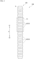
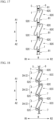
- the stent device 100 is accommodated in the distal end portion of the stent delivery system 150, as shown in FIG. 1 .
- the stent device 100 is accommodated in a gap between the inner tube member 170 and the outer tube member 160 in a state in which the inner tube member 170 is passed therethrough and the diameter thereof is reduced.
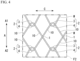
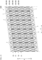
- FIG. 4 is a development view of the stent 110 in an F2 region shown in FIG. 3 .
- the mountain-shaped bent portion 3 and the valley-shaped bent portion 4 intersect with each other in a hook shape, and thus the mountain-shaped bent portion 3 and the valley-shaped bent portion 4 are connected to each other such that they can be moved relative to each other, although they cannot be separated from each other.
- the engagement portions 2 adjacent to each other in the circumferential direction C are disposed at substantially the same position in the longitudinal axis direction A. Furthermore, the engagement portions 2 adjacent to each other in the longitudinal axis direction A are disposed at substantially the same position in the circumferential direction C.
- the plurality of straight line intersection portions 1 are disposed parallel to the circumferential direction C. Further, the plurality of straight line intersection portions 1 are disposed parallel to the circumferential direction C. A first region E1 in which the plurality of straight line intersection portions 1 are disposed and a second region E2 in which the plurality of engagement portions 2 are disposed are alternately disposed in the longitudinal axis direction A.
- the fixation portion (a fixation region) 7 is a region sandwiched between the engagement portions 2 adj acent to each other in the longitudinal axis direction A, and is formed into a roughly diamond-shaped region surrounded by the mountain-shaped bent portion 3 and the valley-shaped bent portion 4.
- the fixation portion 7 is a region in which the inside cover 5 and the outside cover 6 are fixed to each other by bonding, pressure bonding, or the like. Since the inside cover 5 and the outside cover 6 are fixed to each other, the wire W cannot pass through the fixation portion 7.
- the expanded accommodation portion 82 is formed by a non-expanded portion 51 that is a portion of the inside cover 5 extending in the longitudinal axis direction A and an externally expanded portion 62 formed by a portion of the outside cover 6 bulging to the outside R2.
- the expanded accommodation portion 82 is formed in the second region E2 in which the plurality of engagement portions 2 are disposed in the circumferential direction C.
- the expanded accommodation portion 82 accommodates the plurality of engagement portions 2 disposed in the circumferential direction C in an internal region sandwiched between the inside cover 5 and the outside cover 6.
- the expanded accommodation portion 82 may be formed separately for each engagement portion 2.
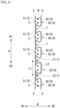
- the fixation portions 7 and the expanded accommodation portions 82 are alternately disposed one by one. Further, in the cross section along the line S1-S1 shown in FIG. 6 , the non-expanded portion 51 of the inside cover 5 closes an opening of the externally expanded portion 62 of the outside cover 6.
- the externally expanded portion 62 is displaceable to a position at which the at least a portion of the externally expanded portion 62 overlaps the fixation portion 7 when viewed in the radial direction R.
- the externally expanded portion 62 of the outside cover 6 may have elasticity, and may be deformed to be displaceable to a position at which the externally expanded portion 62 overlaps the fixation portion 7 when viewed in the radial direction R.
- the fixation portions 7 disposed on both sides of the expanded accommodation portion 82 in the longitudinal axis direction A are defined as a first fixation portion 71 and a second fixation portion 72.
- a path length L2 of the outside cover 6 from the first fixation portion 71 to the second fixation portion 72 is longer than a path length L1 of the inside cover 5 from the first fixation portion 71 to the second fixation portion 72.
- a surface area of the externally expanded portion 62 of the outside cover 6 forming the expanded accommodation portion 82 is larger than a surface area of the non-expanded portion 51 of the inside cover 5 forming the expanded accommodation portion 82.
- the normal accommodation portion 81 and the expanded accommodation portions 82 are alternately disposed one by one.
- the internal region of the expanded accommodation portion 82 is connected to the internal region of the normal accommodation portion 81.
- the engagement portion 2 disposed on the inside in a curving direction will be referred to as an “inside engagement portion 2A.”
- the engagement portion 2 disposed on the outside in the curving direction will be referred to as an “outside engagement portion 2B.”
- the expanded accommodation portions 82 and the expanded accommodation portions 82A are alternately arranged one by one in the longitudinal axis direction A.
- the arrangement aspect of the expanded accommodation portion 82 and the expanded accommodation portion 82A is not limited to this.
- the expanded accommodation portions 82 and the expanded accommodation portions 82A may be arranged such that two consecutive expanded accommodation portions 82 and one expanded accommodation portion 82A are alternately arranged.
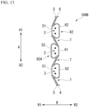
- FIG. 16 is a cross-sectional view of the stent device 100C including a fixation portion 7 and an expanded accommodation portion 82C.
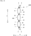
- FIG. 17 is a cross-sectional view of the stent device 100C including a normal accommodation portion 81 and the expanded accommodation portion 82C.
- FIG. 18 is a cross-sectional view of the stent device 100C including an inside engagement portion 2A.
- the cover 120C has the expanded accommodation portion 82C instead of the expanded accommodation portion 82 of the first embodiment.
- the expanded accommodation portion 82C is formed by an internally expanded portion 52C formed by a portion of the inside cover 5 bulging to the inside R1 and an externally expanded portion 62C formed by a portion of the outside cover 6 bulging to the outside R2.
- the expanded accommodation portion 82C accommodates the engagement portion 2 in an internal region sandwiched between the inside cover 5 and the outside cover 6.
- a mountain-shaped bent portion 3 of the inside engagement portion 2A accommodated in the expanded accommodation portion 82C is movable in the first direction A1 to a position at which the mountain-shaped bent portion 3 overlaps the fixation portion 7 when viewed in the radial direction R.
- a valley-shaped bent portion 4 of the inside engagement portion 2A accommodated in the expanded accommodation portion 82C is movable in the second direction A2 to a position at which the mountain-shaped bent portion 4 overlaps the fixation portion 7 when viewed in the radial direction R.
- the stent device 100C even if the stent 110 is covered with the cover 120C, the stent device 100C is easily curved. The curving operation is not impeded by the fixation portion 7 whether the engagement portion 2 is disposed on the inside or on the outside in the curving direction.
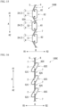
- FIGS. 21 and 22 are cross-sectional views of an expanded accommodation portion 82C2 that is a modification example of the expanded accommodation portion 82C.
- the expanded accommodation portion 82C2 is formed by the internally expanded portion 52C and the externally expanded portion 62C similarly to the expanded accommodation portion 82C.
- a distal end portion 62t of the externally expanded portion 62C is fixed to the mountain-shaped bent portion 3.
- a distal end portion 52t of the internally expanded portion 52C is fixed to the valley-shaped bent portion 4.
- the expanded accommodation portion 82C1 is difficult to be bulked up in the radial direction R.
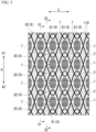
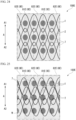
- FIG. 23 is a development view of the stent device 100D developed in the circumferential direction C.
- a method of weaving the stent is not limited to that of the stent 110 of the first embodiment or that of the stent 110D of the fourth embodiment. Other methods of weaving the stent may be used.
- a fifth embodiment of the present invention will be described with reference to FIGS. 24 and 25 .
- the same constituent elements as those already described are designated by the same reference signs, and duplicate description will be omitted.
- a stent device 100E according to the fifth embodiment is accommodated in a stent delivery system 150 similarly to the stent device 100 according to the first embodiment.
- the stent device 100E includes a stent 110 and a cover 120E.
- FIG. 24 is a diagram showing a portion of the stent device 100E.
- the accommodation portion (a non-fixation region) 8E is a region formed by the inside cover 5 and the outside cover 6 that are not fixed to each other similarly to the accommodation portion 8.
- the accommodation portion 8E has a normal accommodation portion 81E and an expanded accommodation portion 82E that is wider than the normal accommodation portion 81E in the radial direction R.
- the normal accommodation portion 81E is formed in a third region E3 in which the plurality of engagement portions 2 are arranged in the longitudinal axis direction A.
- the expanded accommodation portion 82E is formed in a fourth region E4 in which the plurality of straight line intersection portions 1 are arranged in the longitudinal axis direction A.
- the expanded accommodation portion 82E accommodates the plurality of straight line intersection portions 1 disposed in the longitudinal axis direction A and the wires W near the straight line intersection portions 1 in an internal region sandwiched between the inside cover 5 and the outside cover 6.
- FIG. 25 is a diagram showing a portion of the stent device 100E twisted.
- the stent device 100E even if the stent 110 is covered with the cover 120D, the stent device 100E is easily curved.
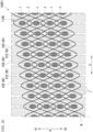
- FIG. 26 is a development view of a stent device 100E1 that is a modification example of the stent device 100E.
- the stent device 100E1 includes a stent 110D and a cover 120E.
- the expanded accommodation portion 82E is formed as a continuous region in the longitudinal axis direction A. For this reason, even in a case where the straight line intersection portion 1 and the engagement portion 2 are disposed in a spiral in the longitudinal axis direction A as in the stent 110D, the manufacturing cost of the expanded accommodation portion 82E is low.
- the present invention can be applied to a stent covered with a cover.
Landscapes
- Health & Medical Sciences (AREA)
- Engineering & Computer Science (AREA)
- Biomedical Technology (AREA)
- Cardiology (AREA)
- Oral & Maxillofacial Surgery (AREA)
- Transplantation (AREA)
- Heart & Thoracic Surgery (AREA)
- Vascular Medicine (AREA)
- Life Sciences & Earth Sciences (AREA)
- Animal Behavior & Ethology (AREA)
- General Health & Medical Sciences (AREA)
- Public Health (AREA)
- Veterinary Medicine (AREA)
- Gastroenterology & Hepatology (AREA)
- Pulmonology (AREA)
- Media Introduction/Drainage Providing Device (AREA)
Applications Claiming Priority (1)
| Application Number | Priority Date | Filing Date | Title |
|---|---|---|---|
| PCT/JP2021/032146 WO2023032084A1 (ja) | 2021-09-01 | 2021-09-01 | ステントデバイスおよびステントデリバリーシステム |
Publications (2)
| Publication Number | Publication Date |
|---|---|
| EP4397284A1 true EP4397284A1 (de) | 2024-07-10 |
| EP4397284A4 EP4397284A4 (de) | 2025-07-02 |
Family
ID=85410928
Family Applications (1)
| Application Number | Title | Priority Date | Filing Date |
|---|---|---|---|
| EP21955974.7A Pending EP4397284A4 (de) | 2021-09-01 | 2021-09-01 | Stentvorrichtung und stenteinführungssystem |
Country Status (6)
| Country | Link |
|---|---|
| US (1) | US20240189125A1 (de) |
| EP (1) | EP4397284A4 (de) |
| JP (1) | JP7587049B2 (de) |
| KR (1) | KR20240033283A (de) |
| CN (1) | CN117897121A (de) |
| WO (1) | WO2023032084A1 (de) |
Families Citing this family (1)
| Publication number | Priority date | Publication date | Assignee | Title |
|---|---|---|---|---|
| CN120857917A (zh) * | 2023-04-05 | 2025-10-28 | 奥林巴斯株式会社 | 支架装置 |
Family Cites Families (7)
| Publication number | Priority date | Publication date | Assignee | Title |
|---|---|---|---|---|
| WO2000038590A1 (en) | 1998-12-23 | 2000-07-06 | Stephen George Edward Barker | Endoluminal stent |
| US20050060020A1 (en) | 2003-09-17 | 2005-03-17 | Scimed Life Systems, Inc. | Covered stent with biologically active material |
| GB2449784B8 (en) * | 2004-02-09 | 2009-04-29 | Cook Biotech Inc | Stent graft devices having collagen coating. |
| US8034096B2 (en) * | 2004-03-31 | 2011-10-11 | Cook Medical Technologies Llc | Stent-graft with graft to graft attachment |
| WO2014010679A1 (ja) * | 2012-07-13 | 2014-01-16 | 株式会社パイオラックスメディカルデバイス | ステント |
| KR101557010B1 (ko) * | 2014-07-11 | 2015-10-02 | 주식회사 비씨엠 | 커버드 스텐트와 그 제조방법 |
| WO2021166156A1 (ja) | 2020-02-20 | 2021-08-26 | オリンパス株式会社 | ステントデリバリーシステム、内視鏡システムおよびステント留置方法 |
-
2021
- 2021-09-01 KR KR1020247006275A patent/KR20240033283A/ko not_active Withdrawn
- 2021-09-01 EP EP21955974.7A patent/EP4397284A4/de active Pending
- 2021-09-01 CN CN202180101942.7A patent/CN117897121A/zh active Pending
- 2021-09-01 WO PCT/JP2021/032146 patent/WO2023032084A1/ja not_active Ceased
- 2021-09-01 JP JP2023544877A patent/JP7587049B2/ja active Active
-
2024
- 2024-02-26 US US18/587,198 patent/US20240189125A1/en active Pending
Also Published As
| Publication number | Publication date |
|---|---|
| CN117897121A (zh) | 2024-04-16 |
| JP7587049B2 (ja) | 2024-11-19 |
| JPWO2023032084A1 (de) | 2023-03-09 |
| KR20240033283A (ko) | 2024-03-12 |
| US20240189125A1 (en) | 2024-06-13 |
| WO2023032084A1 (ja) | 2023-03-09 |
| EP4397284A4 (de) | 2025-07-02 |
Similar Documents
| Publication | Publication Date | Title |
|---|---|---|
| EP2512318B1 (de) | Endoskopschleuse | |
| JP5252606B2 (ja) | 内視鏡用処置具 | |
| JP5064077B2 (ja) | 医療用スネアリング装置 | |
| US20070265494A1 (en) | Flexible and retractable endoscope elevator | |
| JP2016507303A (ja) | 内視鏡スリーブ | |
| JPWO2010082399A1 (ja) | 内視鏡用処置具 | |
| JP5409363B2 (ja) | ループ先端ワイヤガイド | |
| US20240189125A1 (en) | Stent device and stent delivery system | |
| KR20160138004A (ko) | 스텐트 딜리버리 시스템 및 내시경 시스템 | |
| US8419695B2 (en) | Apparatus and method of maintaining insufflation | |
| JP5631177B2 (ja) | 内視鏡誘導用管状部材 | |
| US20260013979A1 (en) | Stent device | |
| EP4397283A1 (de) | Stent und stentanbringungssystem | |
| JP4527111B2 (ja) | 内部空間に挿入するためのガイドワイヤ構造 | |
| US20240245539A1 (en) | Stent and stent delivery system | |
| CN114931692B (zh) | 导管系统 | |
| KR100351320B1 (ko) | 카테터 | |
| WO2018151007A1 (ja) | ステント | |
| CN115040756A (zh) | 导管支撑装置和管腔介入系统 | |
| US12589015B2 (en) | Stent delivery system, endoscope system, and stent indwelling method | |
| JP2026027746A (ja) | ステント | |
| KR20260054409A (ko) | 플라스틱 스텐트 | |
| JP2705701B2 (ja) | 内視鏡システム | |
| JP2022059511A (ja) | カテーテル | |
| JP2000102543A (ja) | 管状医用器具 |
Legal Events
| Date | Code | Title | Description |
|---|---|---|---|
| STAA | Information on the status of an ep patent application or granted ep patent |
Free format text: STATUS: THE INTERNATIONAL PUBLICATION HAS BEEN MADE |
|
| PUAI | Public reference made under article 153(3) epc to a published international application that has entered the european phase |
Free format text: ORIGINAL CODE: 0009012 |
|
| STAA | Information on the status of an ep patent application or granted ep patent |
Free format text: STATUS: REQUEST FOR EXAMINATION WAS MADE |
|
| 17P | Request for examination filed |
Effective date: 20240222 |
|
| AK | Designated contracting states |
Kind code of ref document: A1 Designated state(s): AL AT BE BG CH CY CZ DE DK EE ES FI FR GB GR HR HU IE IS IT LI LT LU LV MC MK MT NL NO PL PT RO RS SE SI SK SM TR |
|
| DAV | Request for validation of the european patent (deleted) | ||
| DAX | Request for extension of the european patent (deleted) | ||
| A4 | Supplementary search report drawn up and despatched |
Effective date: 20250604 |
|
| RIC1 | Information provided on ipc code assigned before grant |
Ipc: A61F 2/90 20130101AFI20250528BHEP |
|
| GRAP | Despatch of communication of intention to grant a patent |
Free format text: ORIGINAL CODE: EPIDOSNIGR1 |
|
| STAA | Information on the status of an ep patent application or granted ep patent |
Free format text: STATUS: GRANT OF PATENT IS INTENDED |
|
| INTG | Intention to grant announced |
Effective date: 20251117 |
|
| GRAJ | Information related to disapproval of communication of intention to grant by the applicant or resumption of examination proceedings by the epo deleted |
Free format text: ORIGINAL CODE: EPIDOSDIGR1 |
|
| STAA | Information on the status of an ep patent application or granted ep patent |
Free format text: STATUS: REQUEST FOR EXAMINATION WAS MADE |
|
| GRAP | Despatch of communication of intention to grant a patent |
Free format text: ORIGINAL CODE: EPIDOSNIGR1 |
|
| STAA | Information on the status of an ep patent application or granted ep patent |
Free format text: STATUS: GRANT OF PATENT IS INTENDED |
|
| INTC | Intention to grant announced (deleted) | ||
| INTG | Intention to grant announced |
Effective date: 20260213 |