EP4397206B1 - Raumtrennvorrichtung, insbesondere duschabtrennung - Google Patents
Raumtrennvorrichtung, insbesondere duschabtrennung Download PDFInfo
- Publication number
- EP4397206B1 EP4397206B1 EP24172345.1A EP24172345A EP4397206B1 EP 4397206 B1 EP4397206 B1 EP 4397206B1 EP 24172345 A EP24172345 A EP 24172345A EP 4397206 B1 EP4397206 B1 EP 4397206B1
- Authority
- EP
- European Patent Office
- Prior art keywords
- clamping
- shelf
- segment
- section
- slot
- Prior art date
- Legal status (The legal status is an assumption and is not a legal conclusion. Google has not performed a legal analysis and makes no representation as to the accuracy of the status listed.)
- Active
Links
Images



Classifications
-
- A—HUMAN NECESSITIES
- A47—FURNITURE; DOMESTIC ARTICLES OR APPLIANCES; COFFEE MILLS; SPICE MILLS; SUCTION CLEANERS IN GENERAL
- A47K—SANITARY EQUIPMENT; ACCESSORIES THEREFOR, e.g. TOILET ACCESSORIES
- A47K3/00—Baths; Showers; Appurtenances therefor
- A47K3/28—Showers or bathing douches
- A47K3/30—Screens or collapsible cabinets for showers or baths
-
- A—HUMAN NECESSITIES
- A47—FURNITURE; DOMESTIC ARTICLES OR APPLIANCES; COFFEE MILLS; SPICE MILLS; SUCTION CLEANERS IN GENERAL
- A47K—SANITARY EQUIPMENT; ACCESSORIES THEREFOR, e.g. TOILET ACCESSORIES
- A47K1/00—Wash-stands; Appurtenances therefor
- A47K1/08—Accessories for toilet tables, e.g. glass plates, supports therefor
-
- A—HUMAN NECESSITIES
- A47—FURNITURE; DOMESTIC ARTICLES OR APPLIANCES; COFFEE MILLS; SPICE MILLS; SUCTION CLEANERS IN GENERAL
- A47K—SANITARY EQUIPMENT; ACCESSORIES THEREFOR, e.g. TOILET ACCESSORIES
- A47K10/00—Body-drying implements; Toilet paper; Holders therefor
- A47K10/04—Towel racks; Towel rails; Towel rods; Towel rolls, e.g. rotatable
- A47K10/10—Towel racks; Towel rails; Towel rods; Towel rolls, e.g. rotatable characterised by being mounted on cabinets, walls, doors, or the like
-
- A—HUMAN NECESSITIES
- A47—FURNITURE; DOMESTIC ARTICLES OR APPLIANCES; COFFEE MILLS; SPICE MILLS; SUCTION CLEANERS IN GENERAL
- A47K—SANITARY EQUIPMENT; ACCESSORIES THEREFOR, e.g. TOILET ACCESSORIES
- A47K3/00—Baths; Showers; Appurtenances therefor
- A47K3/001—Accessories for baths, not provided for in other subgroups of group A47K3/00; Insertions, e.g. for babies; Tubs suspended or inserted in baths; Security or alarm devices; Protecting linings or coverings; Devices for cleaning or disinfecting baths; Bath insulation
-
- A—HUMAN NECESSITIES
- A47—FURNITURE; DOMESTIC ARTICLES OR APPLIANCES; COFFEE MILLS; SPICE MILLS; SUCTION CLEANERS IN GENERAL
- A47K—SANITARY EQUIPMENT; ACCESSORIES THEREFOR, e.g. TOILET ACCESSORIES
- A47K3/00—Baths; Showers; Appurtenances therefor
- A47K3/28—Showers or bathing douches
- A47K3/281—Accessories for showers or bathing douches, e.g. cleaning devices for walls or floors of showers
-
- F—MECHANICAL ENGINEERING; LIGHTING; HEATING; WEAPONS; BLASTING
- F16—ENGINEERING ELEMENTS AND UNITS; GENERAL MEASURES FOR PRODUCING AND MAINTAINING EFFECTIVE FUNCTIONING OF MACHINES OR INSTALLATIONS; THERMAL INSULATION IN GENERAL
- F16B—DEVICES FOR FASTENING OR SECURING CONSTRUCTIONAL ELEMENTS OR MACHINE PARTS TOGETHER, e.g. NAILS, BOLTS, CIRCLIPS, CLAMPS, CLIPS OR WEDGES; JOINTS OR JOINTING
- F16B2/00—Friction-grip releasable fastenings
- F16B2/02—Clamps, i.e. with gripping action effected by positive means other than the inherent resistance to deformation of the material of the fastening
- F16B2/06—Clamps, i.e. with gripping action effected by positive means other than the inherent resistance to deformation of the material of the fastening external, i.e. with contracting action
- F16B2/065—Clamps, i.e. with gripping action effected by positive means other than the inherent resistance to deformation of the material of the fastening external, i.e. with contracting action using screw-thread elements
-
- F—MECHANICAL ENGINEERING; LIGHTING; HEATING; WEAPONS; BLASTING
- F16—ENGINEERING ELEMENTS AND UNITS; GENERAL MEASURES FOR PRODUCING AND MAINTAINING EFFECTIVE FUNCTIONING OF MACHINES OR INSTALLATIONS; THERMAL INSULATION IN GENERAL
- F16B—DEVICES FOR FASTENING OR SECURING CONSTRUCTIONAL ELEMENTS OR MACHINE PARTS TOGETHER, e.g. NAILS, BOLTS, CIRCLIPS, CLAMPS, CLIPS OR WEDGES; JOINTS OR JOINTING
- F16B5/00—Joining sheets or plates, e.g. panels, to one another or to strips or bars parallel to them
- F16B5/06—Joining sheets or plates, e.g. panels, to one another or to strips or bars parallel to them by means of clamps or clips
- F16B5/0607—Joining sheets or plates, e.g. panels, to one another or to strips or bars parallel to them by means of clamps or clips joining sheets or plates to each other
- F16B5/0614—Joining sheets or plates, e.g. panels, to one another or to strips or bars parallel to them by means of clamps or clips joining sheets or plates to each other in angled relationship
-
- A—HUMAN NECESSITIES
- A47—FURNITURE; DOMESTIC ARTICLES OR APPLIANCES; COFFEE MILLS; SPICE MILLS; SUCTION CLEANERS IN GENERAL
- A47B—TABLES; DESKS; OFFICE FURNITURE; CABINETS; DRAWERS; GENERAL DETAILS OF FURNITURE
- A47B96/00—Details of cabinets, racks or shelf units not covered by a single one of groups A47B43/00 - A47B95/00; General details of furniture
- A47B96/02—Shelves
- A47B96/027—Cantilever shelves
- A47B96/028—Cantilever shelves characterised by support bracket location means, e.g. fixing means between support bracket and shelf
-
- A—HUMAN NECESSITIES
- A47—FURNITURE; DOMESTIC ARTICLES OR APPLIANCES; COFFEE MILLS; SPICE MILLS; SUCTION CLEANERS IN GENERAL
- A47K—SANITARY EQUIPMENT; ACCESSORIES THEREFOR, e.g. TOILET ACCESSORIES
- A47K2201/00—Details of connections of bathroom accessories, e.g. fixing soap or towel holder to a wall
Definitions
- the object of the present invention is therefore to provide a room separating device, in particular a shower partition, which overcomes the described disadvantages of the prior art.
- Technology largely avoids this and enables a simple, reliable coupling of a shelf to a room divider segment, especially made of glass.
- the invention solves the problem by means of a clamping device for producing a force-fit coupling between the room divider segment and the shelf according to claim 1.
- a force-fit, clamping connection for fastening a shelf to a room divider segment is advantageously proposed while avoiding a structural change to the room divider segment.
- the production of holes in the room divider segment, in particular a glass or plastic pane, is avoided according to the invention, thereby saving the drilling work step and avoiding the risk of damage during production or assembly.
- Due to the clamping device according to the invention the position of the shelf coupled to it can be flexibly adjusted during assembly and also changed afterwards; especially since nowadays particular emphasis is placed on flexibility in order to meet the requirements or wishes of customers and specialist retailers and tradesmen.
- the height of the shelf can be selected according to individual wishes and can also be changed later without having to make new holes. For example, it is conceivable that a tall person would like the shelf to be attached at a higher position than a short person. Depending on the respective life situation, dismantling and then reassembling the shelf in a new, more advantageous position is particularly easy with the present invention.
- the invention of the type mentioned at the outset is characterized in that the clamping device has a first clamping section and, spaced therefrom, a second clamping section, which are spaced apart such that the room divider segment can be inserted into the space between the first and second clamping sections.
- the clamping device has a first clamping section and, spaced therefrom, a second clamping section, which are spaced apart such that the room divider segment can be inserted into the space between the first and second clamping sections.
- the first clamping section and the second clamping section are connected to one another by means of a connecting section, wherein the connecting section preferably forms a stop for the room divider segment.
- the connecting section enables the clamping forces to be transferred in a simple manner.
- it serves as a stop for the room divider segment during assembly, whereby the desired position of the shelf on the room divider segment can be easily achieved and an optimal alignment of the clamping device on the room divider segment and as a result an optimal power transmission can take place.
- a fastening section for fastening the clamping device to the shelf is provided adjacent to the first and second clamping sections. This serves primarily the purpose of mounting the shelf to the clamping device in a precisely positioned manner.
- the fastening section has two spaced legs between which the room divider segment is arranged in the assembled state.
- such an embodiment primarily increases the stability of the shelf on the clamping device on the room divider segment.
- each leg of the fastening section has a flange-like projection that can be fastened to the shelf by means of a screw connection and can be inserted at least partially, preferably completely, into the recess of the shelf. This ensures a simple, precisely positioned and stable fastening of the shelf to the clamping device.
- the fastening section and the first and second clamping sections are arranged substantially at right angles to one another.
- Such an embodiment results in a favorable load distribution due to a preferably substantially L-shaped design of the legs in combination with the clamping sections.
- the shelf has a (first) slot-shaped cutout which is designed to accommodate the room divider segment.
- the cutout enables easy insertion during assembly and allows the shelf to be used on both sides of the room divider.
- the cutout provides additional stability during attachment, as it prevents the shelf from tipping over.
- the slot-shaped cutout has a protective layer at least partially along its inner contour, which is in contact with the room divider segment when installed.
- the protective layer has a positive impact, shock and vibration dampening effect.
- the protective layer is also designed as a type of sealing lip and thus represents overflow protection at the interface between the shelf and the room divider segment.
- the protective layer preferably consists of an elastic, preferably rubber-like material.
- a highly elastic, preferably rubber-like material also increases friction. The increase in friction serves the purpose of exerting an additional holding force along the contact surface between the shelf and the room divider segment.
- the shelf is preferably designed as a one-piece board. This is due not only to aesthetic reasons but also to reduced assembly effort. In an alternative embodiment of the invention, it is conceivable that the shelf is designed as a basket.
- the shelf particularly preferably has a further (second) slot-shaped cutout, so that a holding segment is formed on the shelf, which is preferably designed as a towel holder.
- the design of the holding segment at a free end of a shower cubicle has the advantage that, in contrast to conventional shelves that can only be mounted inside shower cubicles, a useful towel holder can be sensibly combined with a shelf.
- first slot-shaped cutout and the second slot-shaped cutout are arranged at an angle to one another, preferably in a range between 80 and 110°, particularly preferably at an angle of approximately 90°.
- a substantially right-angled arrangement has the advantage that a user of the holding segment can reach the held object, preferably a towel, particularly easily. Furthermore, this further development of the invention ensures optimal use of space with optimized storage space.
- At least one clamping section has at least one clamping means for applying a clamping force to the room divider segment, which is preferably designed as a screw and interacts with a thread formed on the clamping section.
- Setting a clamping force via a thread represents a simple and, above all, precise way of applying such a clamping force, for example using a torque wrench, without the clamping force becoming too great and possibly damaging the room divider segment.
- the clamping means has a preferably disc-shaped pressure-stable contact element which is in contact with the room divider segment when assembled.
- the introduction and transmission of force by a screw-shaped clamping means results in a largely point-like pressure force on the room divider segment.
- the use of such a contact element ensures a shift in the pressure stress and a distribution of the stress peaks. This means that a gentle introduction of force is possible even on materials that are sensitive to breakage.
- a further embodiment has a cover attached to a clamping section to shield the clamping means from external influences. This is necessary for a visually uniform, aesthetically high-quality overall impression of the device, and it also reduces stress from environmental influences, for example from a direct water jet on the clamping means.
- a protective layer is arranged on at least one clamping section, which is in contact with the room divider segment when installed and is preferably made of a friction-increasing material.
- the force of the clamping section is introduced via the protective layer, which on the one hand has an impact, shock and vibration dampening effect and on the other hand can absorb and distribute stress peaks.
- the room divider segment is a glass wall, wherein the glass wall is coupled to the shelf at a freestanding end.
- the in Figure 1 The room divider 1 shown has a room divider segment 2 in the form of a substantially rectangular pane made of glass or plastic and a shelf 6 attached to the room divider segment 2 with a clamping device 4, on which Objects can be placed or placed.
- the shelf 6 is designed in the form of a one-piece board or a plate or a bowl made of various materials, such as plastic, metal, coated wood. In the assembled state, the shelf 6 is arranged essentially horizontally during operation and essentially at right angles to the room divider segment 2, which is arranged vertically during operation.
- the shelf 6 has a first slot-shaped cutout 8, which in particular has a width that corresponds at least to the thickness of the room divider segment 2 and a length that corresponds to a multiple of its width.
- the first slot-shaped cutout 8 is designed to accommodate the room divider segment 2 and to form a guide for the room divider segment 2 during assembly.
- the slot-shaped cutout 8 or the thickness of the room divider segment 2 can be selected such that the shelf 6 is additionally held or supported in its right-angled position relative to the room divider segment 2.
- a second, in particular slot-shaped, cutout 10 which in this embodiment forms a holding segment 12 and is preferably designed as a towel holder.
- the slot-shaped cutout 10 is essentially rectangular, but other shapes are also conceivable, for example curved or partially curved shapes.
- the clamping device 4 is arranged below the shelf 6 and is designed to provide a clamping force for fixing and holding the shelf 6 on the room divider segment 2, which is preferably applied to a lateral end region or free end of the room divider segment 2.
- the first slot-shaped cutout 8 in the shelf 6 runs essentially in the middle and extends from one end almost over the entire length of the shelf 6 to the other end, but it is alternatively also possible according to the invention for the slot-shaped cutout 8 not to run in the middle but offset to one side, so that the shelf 6 is arranged asymmetrically relative to the room divider segment 2.
- the entire length of the shelf 6 does not extend across the entire width of the room divider segment 2; in this respect, too, different variants are possible.
- the second slot-shaped cutout 10 is formed on an end region of the shelf 6 which protrudes from the room divider segment 2 and protrudes beyond the room divider segment 2 in the assembled state and runs essentially at a right angle relative to the first slot-shaped cutout 8; other angles or shapes are also possible here. It would also be conceivable for several slot-shaped cutouts 10 to be formed in the shelf 6, for example to be able to hang several towels over them.
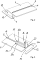
- the Figures 2 and 3 each show a perspective view of a clamping device 4 connected to the shelf 6.
- the first slot-shaped cutout 8 has a damping or protective layer 14, which can form a type of sealing lip above the shelf 6 and is preferably made of an elastically and/or plastically deformable material, preferably plastic; it can, for example, be glued to the shelf 6.
- FIG 3 shows, among other things, a more detailed view of the clamping device 4.
- the clamping device 4 is essentially L-shaped and has a fastening section 15 for fastening the shelf 6 and the clamping device 4 to one another and a first clamping section 16 and a second clamping section 18, with the help of which, together with other components, the clamping force for clamping the shelf 6 to the room divider segment 2 can be applied.
- the first and the second clamping sections 16, 18 are connected to one another by a connecting section 20, wherein the connecting section 20, in addition to the purpose of transmitting the clamping force from the first to the second clamping section 16, 18, also serves as a stop for the room divider segment 2 when assembling the clamping device 4.
- the fastening section 15 of the clamping device 4 has two spaced legs 22a and 22b, between which the room divider segment 2 is arranged in the assembled state. Both legs 22a and 22b of the fastening section 15 each have a flange-like projection which serves to fasten the shelf 6 to the clamping device 4 by means of a screw connection. For this purpose, screws are inserted through holes formed in the flange-like projections and screwed into the shelf 6. Preferably, at least four screws are used.
- the fastening section 15 is preferably arranged flush on the underside of the shelf 6 and preferably at least partially within a recess 34a and 34b formed on the underside of the shelf 6.
- the shelf 6 has two recesses 34a and 34b on its underside, wherein the legs 22a and 22b of the fastening section 15 of the clamping device 4 each have a flange-like projection which can be inserted into a respective recess 34a and 34b of the shelf 6.
- Figure 4 shows a side view of a shelf 6 according to the invention attached to a clamping device 4. It can be seen that the arrangement of the first and second clamping portion 16, 18 is substantially perpendicular to the fastening portion 15.
- Figure 5 shows a sectional view of a shelf 6 according to the invention attached to a clamping device 4. It can be seen that the first clamping section 16 is spaced to the second clamping section 18, at least corresponding to the thickness of the room divider segment 2.
- the first clamping section 16 has three clamping means 24. These clamping means 24 comprise at least one screw or one threaded pin 21 and a respective disk-shaped pressure-stable contact element 26, preferably of high mechanical strength, which is connected to the threaded pin 21 at one end.
- the contact element 26 consists of polysulfone (PSU), although materials with similar pressure-stable properties can also be used.
- the screws or threaded pins 21 are arranged within holes formed with an internal thread, which are formed in the clamping section 16. In the initial example, three threaded pins 21 and corresponding holes are provided, but the number can easily be varied.
- the contact element 26 establishes a connection between the threaded pin 21 and the room divider segment 2 for transmitting the clamping force.
- a cover 28 is attached to the first clamping section 16 on the clamping means 24 with an adhesive tape 30.
- a protective layer 32 is arranged on the second clamping section 18, preferably glued on, which creates a connection between the second clamping section 18 and the room divider segment 2 when the clamping device 4 is mounted.
- the protective layer 32 is preferably made of a friction-increasing material.
- the protective layer 32 is made of polyvinyl chloride (PVC), whereby both hard and soft PVC can be used, although materials with similar properties, in particular those that reduce stress peaks, can also be used.
- the protective layer 14 is arranged along the inside of the first slot-shaped cutout 8 of the shelf 6.
- the protective layer 14 consists of an elastic, preferably rubber-like material.
- the protective layer 14 consists of ethylene vinyl acetate (EVA), but it is also conceivable to use materials with similar impact, shock and vibration-damping properties for the protective layer 14, which preferably also causes an increase in friction on the contact surface created in the assembled state between the shelf 6 and the room divider segment 2.
Landscapes
- Health & Medical Sciences (AREA)
- Public Health (AREA)
- Engineering & Computer Science (AREA)
- General Engineering & Computer Science (AREA)
- Epidemiology (AREA)
- General Health & Medical Sciences (AREA)
- Mechanical Engineering (AREA)
- Residential Or Office Buildings (AREA)
- Furniture Connections (AREA)
- Supports Or Holders For Household Use (AREA)
- Domestic Plumbing Installations (AREA)
- Assembled Shelves (AREA)
- Connection Of Plates (AREA)
- Bathtubs, Showers, And Their Attachments (AREA)
- Clamps And Clips (AREA)
Applications Claiming Priority (2)
| Application Number | Priority Date | Filing Date | Title |
|---|---|---|---|
| DE202019101308.7U DE202019101308U1 (de) | 2019-03-08 | 2019-03-08 | Raumtrennvorrichtung, insbesondere Duschabtrennung |
| EP20161846.9A EP3705009B1 (de) | 2019-03-08 | 2020-03-09 | Raumtrennvorrichtung, insbesondere duschabtrennung |
Related Parent Applications (2)
| Application Number | Title | Priority Date | Filing Date |
|---|---|---|---|
| EP20161846.9A Division EP3705009B1 (de) | 2019-03-08 | 2020-03-09 | Raumtrennvorrichtung, insbesondere duschabtrennung |
| EP20161846.9A Division-Into EP3705009B1 (de) | 2019-03-08 | 2020-03-09 | Raumtrennvorrichtung, insbesondere duschabtrennung |
Publications (4)
| Publication Number | Publication Date |
|---|---|
| EP4397206A2 EP4397206A2 (de) | 2024-07-10 |
| EP4397206A3 EP4397206A3 (de) | 2024-07-17 |
| EP4397206B1 true EP4397206B1 (de) | 2025-02-26 |
| EP4397206C0 EP4397206C0 (de) | 2025-02-26 |
Family
ID=65996209
Family Applications (2)
| Application Number | Title | Priority Date | Filing Date |
|---|---|---|---|
| EP24172345.1A Active EP4397206B1 (de) | 2019-03-08 | 2020-03-09 | Raumtrennvorrichtung, insbesondere duschabtrennung |
| EP20161846.9A Active EP3705009B1 (de) | 2019-03-08 | 2020-03-09 | Raumtrennvorrichtung, insbesondere duschabtrennung |
Family Applications After (1)
| Application Number | Title | Priority Date | Filing Date |
|---|---|---|---|
| EP20161846.9A Active EP3705009B1 (de) | 2019-03-08 | 2020-03-09 | Raumtrennvorrichtung, insbesondere duschabtrennung |
Country Status (5)
| Country | Link |
|---|---|
| EP (2) | EP4397206B1 (es) |
| DE (1) | DE202019101308U1 (es) |
| ES (2) | ES3063519T3 (es) |
| HU (1) | HUE071365T2 (es) |
| PL (2) | PL3705009T3 (es) |
Families Citing this family (2)
| Publication number | Priority date | Publication date | Assignee | Title |
|---|---|---|---|---|
| EP4000484A1 (en) * | 2020-11-16 | 2022-05-25 | Svedbergs i Dalstorp AB | Shower partition comprising means for fastening a textile or textile-like material |
| DE202024104768U1 (de) | 2024-08-22 | 2025-04-14 | Hüppe GmbH | Sanitärinstallation zum Abgrenzen eines Duschplatzes und Ausbilden eines Sanitärmöbels |
Family Cites Families (6)
| Publication number | Priority date | Publication date | Assignee | Title |
|---|---|---|---|---|
| US6588030B1 (en) * | 2002-10-21 | 2003-07-08 | Alan T. Wulff | Soap and accessory support |
| DE202004018077U1 (de) * | 2004-11-20 | 2005-03-03 | Mez, Alfred | Ablage für Duschutensilien |
| GB2490182B (en) * | 2011-08-31 | 2013-03-06 | Antoni Harold Nikolas Gontar | Shower enclosure profile |
| GB2507517B (en) * | 2012-10-31 | 2016-09-07 | Coram Showers Ltd | Wall channel system |
| US9958112B1 (en) * | 2015-05-04 | 2018-05-01 | Brian Johnson | Mounting system for holding items |
| DE202017102988U1 (de) * | 2017-05-18 | 2017-07-20 | Friedr. Wilh. Giese Gmbh & Co. Kg | Sanitäre Ausstattungsarmatur |
-
2019
- 2019-03-08 DE DE202019101308.7U patent/DE202019101308U1/de active Active
-
2020
- 2020-03-09 PL PL20161846.9T patent/PL3705009T3/pl unknown
- 2020-03-09 ES ES20161846T patent/ES3063519T3/es active Active
- 2020-03-09 EP EP24172345.1A patent/EP4397206B1/de active Active
- 2020-03-09 ES ES24172345T patent/ES3028234T3/es active Active
- 2020-03-09 HU HUE24172345A patent/HUE071365T2/hu unknown
- 2020-03-09 PL PL24172345.1T patent/PL4397206T3/pl unknown
- 2020-03-09 EP EP20161846.9A patent/EP3705009B1/de active Active
Also Published As
| Publication number | Publication date |
|---|---|
| PL4397206T3 (pl) | 2025-07-28 |
| EP3705009A3 (de) | 2020-11-25 |
| ES3028234T3 (en) | 2025-06-18 |
| EP4397206A2 (de) | 2024-07-10 |
| EP3705009A2 (de) | 2020-09-09 |
| ES3063519T3 (en) | 2026-04-16 |
| EP3705009C0 (de) | 2025-12-10 |
| EP3705009B1 (de) | 2025-12-10 |
| PL3705009T3 (pl) | 2026-04-13 |
| EP4397206A3 (de) | 2024-07-17 |
| DE202019101308U1 (de) | 2019-03-14 |
| EP4397206C0 (de) | 2025-02-26 |
| HUE071365T2 (hu) | 2025-08-28 |
Similar Documents
| Publication | Publication Date | Title |
|---|---|---|
| EP2882316B1 (de) | Anordnung zur befestigung einer ablagevorrichtung sowie ablagevorrichtung | |
| EP2750550B1 (de) | Schublade | |
| DE202013101469U1 (de) | Duschtür-Baugruppe | |
| DE2933303A1 (de) | Befestigungsvorrichtung fuer wandschraenkchen, spiegel, regale u.dgl. | |
| DE2024935A1 (de) | Spreizdübel zur Abstandsbefestigung von Verkleidungselementen oder Bauteilen an einer Wand od. dgl | |
| EP3705009B1 (de) | Raumtrennvorrichtung, insbesondere duschabtrennung | |
| EP0784951A1 (de) | Vorrichtung mit Funktionsteilen | |
| EP2120647B1 (de) | Befestigungsvorrichtung in einem möbelkorpus | |
| DE102014114339A1 (de) | Führungseinrichtung zur Führung einer Schiebetür und Schrankmöbel | |
| EP4067594A1 (de) | Verbindungsbeschlag | |
| EP3695748B1 (de) | Einbauschrankanordnung | |
| DE19701428C2 (de) | In einer Ausnehmung einer Türbekleidung angeordnetes Winkelschließblech | |
| EP1645211B1 (de) | Schublade mit einer Stabilisierungsvorrichtung | |
| DE102010018368A1 (de) | Trennwandsystem für den Innenausbau | |
| DE10211709C1 (de) | Duschkabine mit einer wenigstens eine Glasplatte aufweisenden Duschtrennwand | |
| DE29816875U1 (de) | Vorrichtung zur Befestigung von Zusatzteilen | |
| DE102006016022B4 (de) | Vorrichtung zur drehbaren Halterung von zwei Flächenelementen und deren Verwendung | |
| DE202017105504U1 (de) | Befestigungsvorrichtung für Steckkarten | |
| EP1323933B1 (de) | Halterung für eine langgestreckte Profilschiene aus einem nach unten hin offenen C-Profil | |
| AT335710B (de) | Verbundhaken | |
| EP1591041B1 (de) | Griffelement | |
| EP0539424B1 (de) | Profilschiene | |
| EP2096228B1 (de) | Montage- und Haltevorrichtung | |
| DE202010004269U1 (de) | Verbindersystem für Terrassenkonstruktionen | |
| DE3907797A1 (de) | Waschtisch mit einer traegerplatte und wenigstens einem handtuchhalter |
Legal Events
| Date | Code | Title | Description |
|---|---|---|---|
| PUAI | Public reference made under article 153(3) epc to a published international application that has entered the european phase |
Free format text: ORIGINAL CODE: 0009012 |
|
| STAA | Information on the status of an ep patent application or granted ep patent |
Free format text: STATUS: REQUEST FOR EXAMINATION WAS MADE |
|
| REG | Reference to a national code |
Ref country code: DE Free format text: PREVIOUS MAIN CLASS: A47B0096020000 Ipc: A47K0003280000 Ref country code: DE Ref legal event code: R079 Ref document number: 502020010510 Country of ref document: DE Free format text: PREVIOUS MAIN CLASS: A47B0096020000 Ipc: A47K0003280000 |
|
| PUAL | Search report despatched |
Free format text: ORIGINAL CODE: 0009013 |
|
| 17P | Request for examination filed |
Effective date: 20240425 |
|
| AC | Divisional application: reference to earlier application |
Ref document number: 3705009 Country of ref document: EP Kind code of ref document: P |
|
| AK | Designated contracting states |
Kind code of ref document: A2 Designated state(s): AL AT BE BG CH CY CZ DE DK EE ES FI FR GB GR HR HU IE IS IT LI LT LU LV MC MK MT NL NO PL PT RO RS SE SI SK SM TR |
|
| AK | Designated contracting states |
Kind code of ref document: A3 Designated state(s): AL AT BE BG CH CY CZ DE DK EE ES FI FR GB GR HR HU IE IS IT LI LT LU LV MC MK MT NL NO PL PT RO RS SE SI SK SM TR |
|
| RIC1 | Information provided on ipc code assigned before grant |
Ipc: A47B 96/02 20060101ALN20240610BHEP Ipc: F16B 5/06 20060101ALI20240610BHEP Ipc: F16B 2/06 20060101ALI20240610BHEP Ipc: A47K 10/10 20060101ALI20240610BHEP Ipc: A47K 3/00 20060101ALI20240610BHEP Ipc: A47K 3/30 20060101ALI20240610BHEP Ipc: A47K 1/08 20060101ALI20240610BHEP Ipc: A47K 3/28 20060101AFI20240610BHEP |
|
| RBV | Designated contracting states (corrected) |
Designated state(s): AL AT BE BG CH CY CZ DE DK EE ES FI FR GB GR HR HU IE IS IT LI LT LU LV MC MK MT NL NO PL PT RO RS SE SI SK SM TR |
|
| GRAP | Despatch of communication of intention to grant a patent |
Free format text: ORIGINAL CODE: EPIDOSNIGR1 |
|
| STAA | Information on the status of an ep patent application or granted ep patent |
Free format text: STATUS: GRANT OF PATENT IS INTENDED |
|
| INTG | Intention to grant announced |
Effective date: 20240926 |
|
| GRAS | Grant fee paid |
Free format text: ORIGINAL CODE: EPIDOSNIGR3 |
|
| GRAA | (expected) grant |
Free format text: ORIGINAL CODE: 0009210 |
|
| STAA | Information on the status of an ep patent application or granted ep patent |
Free format text: STATUS: THE PATENT HAS BEEN GRANTED |
|
| AC | Divisional application: reference to earlier application |
Ref document number: 3705009 Country of ref document: EP Kind code of ref document: P |
|
| AK | Designated contracting states |
Kind code of ref document: B1 Designated state(s): AL AT BE BG CH CY CZ DE DK EE ES FI FR GB GR HR HU IE IS IT LI LT LU LV MC MK MT NL NO PL PT RO RS SE SI SK SM TR |
|
| REG | Reference to a national code |
Ref country code: GB Ref legal event code: FG4D Free format text: NOT ENGLISH |
|
| REG | Reference to a national code |
Ref country code: CH Ref legal event code: EP |
|
| REG | Reference to a national code |
Ref country code: DE Ref legal event code: R096 Ref document number: 502020010510 Country of ref document: DE |
|
| REG | Reference to a national code |
Ref country code: IE Ref legal event code: FG4D Free format text: LANGUAGE OF EP DOCUMENT: GERMAN |
|
| U01 | Request for unitary effect filed |
Effective date: 20250319 |
|
| U07 | Unitary effect registered |
Designated state(s): AT BE BG DE DK EE FI FR IT LT LU LV MT NL PT RO SE SI Effective date: 20250325 |
|
| U20 | Renewal fee for the european patent with unitary effect paid |
Year of fee payment: 6 Effective date: 20250402 |
|
| REG | Reference to a national code |
Ref country code: ES Ref legal event code: FG2A Ref document number: 3028234 Country of ref document: ES Kind code of ref document: T3 Effective date: 20250618 |
|
| PG25 | Lapsed in a contracting state [announced via postgrant information from national office to epo] |
Ref country code: RS Free format text: LAPSE BECAUSE OF FAILURE TO SUBMIT A TRANSLATION OF THE DESCRIPTION OR TO PAY THE FEE WITHIN THE PRESCRIBED TIME-LIMIT Effective date: 20250526 |
|
| PGFP | Annual fee paid to national office [announced via postgrant information from national office to epo] |
Ref country code: ES Payment date: 20250506 Year of fee payment: 6 |
|
| PG25 | Lapsed in a contracting state [announced via postgrant information from national office to epo] |
Ref country code: IS Free format text: LAPSE BECAUSE OF FAILURE TO SUBMIT A TRANSLATION OF THE DESCRIPTION OR TO PAY THE FEE WITHIN THE PRESCRIBED TIME-LIMIT Effective date: 20250626 Ref country code: NO Free format text: LAPSE BECAUSE OF FAILURE TO SUBMIT A TRANSLATION OF THE DESCRIPTION OR TO PAY THE FEE WITHIN THE PRESCRIBED TIME-LIMIT Effective date: 20250526 |
|
| PG25 | Lapsed in a contracting state [announced via postgrant information from national office to epo] |
Ref country code: HR Free format text: LAPSE BECAUSE OF FAILURE TO SUBMIT A TRANSLATION OF THE DESCRIPTION OR TO PAY THE FEE WITHIN THE PRESCRIBED TIME-LIMIT Effective date: 20250226 |
|
| PG25 | Lapsed in a contracting state [announced via postgrant information from national office to epo] |
Ref country code: GR Free format text: LAPSE BECAUSE OF FAILURE TO SUBMIT A TRANSLATION OF THE DESCRIPTION OR TO PAY THE FEE WITHIN THE PRESCRIBED TIME-LIMIT Effective date: 20250527 |
|
| REG | Reference to a national code |
Ref country code: HU Ref legal event code: AG4A Ref document number: E071365 Country of ref document: HU |
|
| PG25 | Lapsed in a contracting state [announced via postgrant information from national office to epo] |
Ref country code: SM Free format text: LAPSE BECAUSE OF FAILURE TO SUBMIT A TRANSLATION OF THE DESCRIPTION OR TO PAY THE FEE WITHIN THE PRESCRIBED TIME-LIMIT Effective date: 20250226 |
|
| REG | Reference to a national code |
Ref country code: CH Ref legal event code: H13 Free format text: ST27 STATUS EVENT CODE: U-0-0-H10-H13 (AS PROVIDED BY THE NATIONAL OFFICE) Effective date: 20251023 |
|
| PG25 | Lapsed in a contracting state [announced via postgrant information from national office to epo] |
Ref country code: SK Free format text: LAPSE BECAUSE OF FAILURE TO SUBMIT A TRANSLATION OF THE DESCRIPTION OR TO PAY THE FEE WITHIN THE PRESCRIBED TIME-LIMIT Effective date: 20250226 |
|
| PG25 | Lapsed in a contracting state [announced via postgrant information from national office to epo] |
Ref country code: MC Free format text: LAPSE BECAUSE OF FAILURE TO SUBMIT A TRANSLATION OF THE DESCRIPTION OR TO PAY THE FEE WITHIN THE PRESCRIBED TIME-LIMIT Effective date: 20250226 |
|
| PLBE | No opposition filed within time limit |
Free format text: ORIGINAL CODE: 0009261 |
|
| STAA | Information on the status of an ep patent application or granted ep patent |
Free format text: STATUS: NO OPPOSITION FILED WITHIN TIME LIMIT |
|
| PG25 | Lapsed in a contracting state [announced via postgrant information from national office to epo] |
Ref country code: CH Free format text: LAPSE BECAUSE OF NON-PAYMENT OF DUE FEES Effective date: 20250331 |
|
| PG25 | Lapsed in a contracting state [announced via postgrant information from national office to epo] |
Ref country code: IE Free format text: LAPSE BECAUSE OF NON-PAYMENT OF DUE FEES Effective date: 20250309 |
|
| GBPC | Gb: european patent ceased through non-payment of renewal fee |
Effective date: 20250526 |
|
| 26N | No opposition filed |
Effective date: 20251127 |
|
| U20 | Renewal fee for the european patent with unitary effect paid |
Year of fee payment: 7 Effective date: 20260123 |
|
| PG25 | Lapsed in a contracting state [announced via postgrant information from national office to epo] |
Ref country code: GB Free format text: LAPSE BECAUSE OF NON-PAYMENT OF DUE FEES Effective date: 20250526 |
|
| PGFP | Annual fee paid to national office [announced via postgrant information from national office to epo] |
Ref country code: HU Payment date: 20260306 Year of fee payment: 7 |
|
| PGFP | Annual fee paid to national office [announced via postgrant information from national office to epo] |
Ref country code: TR Payment date: 20260302 Year of fee payment: 7 |
|
| PGFP | Annual fee paid to national office [announced via postgrant information from national office to epo] |
Ref country code: CZ Payment date: 20260224 Year of fee payment: 7 |
|
| PGFP | Annual fee paid to national office [announced via postgrant information from national office to epo] |
Ref country code: PL Payment date: 20260126 Year of fee payment: 7 |