EP4391202A1 - Batteriemodul - Google Patents
Batteriemodul Download PDFInfo
- Publication number
- EP4391202A1 EP4391202A1 EP23835894.9A EP23835894A EP4391202A1 EP 4391202 A1 EP4391202 A1 EP 4391202A1 EP 23835894 A EP23835894 A EP 23835894A EP 4391202 A1 EP4391202 A1 EP 4391202A1
- Authority
- EP
- European Patent Office
- Prior art keywords
- battery module
- electrode lead
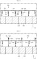
- present disclosure
- junction portion
- module according
- Prior art date
- Legal status (The legal status is an assumption and is not a legal conclusion. Google has not performed a legal analysis and makes no representation as to the accuracy of the status listed.)
- Pending
Links
Images



Classifications
-
- H—ELECTRICITY
- H01—ELECTRIC ELEMENTS
- H01M—PROCESSES OR MEANS, e.g. BATTERIES, FOR THE DIRECT CONVERSION OF CHEMICAL ENERGY INTO ELECTRICAL ENERGY
- H01M50/00—Constructional details or processes of manufacture of the non-active parts of electrochemical cells other than fuel cells, e.g. hybrid cells
- H01M50/20—Mountings; Secondary casings or frames; Racks, modules or packs; Suspension devices; Shock absorbers; Transport or carrying devices; Holders
- H01M50/204—Racks, modules or packs for multiple batteries or multiple cells
- H01M50/207—Racks, modules or packs for multiple batteries or multiple cells characterised by their shape
- H01M50/211—Racks, modules or packs for multiple batteries or multiple cells characterised by their shape adapted for pouch cells
-
- H—ELECTRICITY
- H01—ELECTRIC ELEMENTS
- H01M—PROCESSES OR MEANS, e.g. BATTERIES, FOR THE DIRECT CONVERSION OF CHEMICAL ENERGY INTO ELECTRICAL ENERGY
- H01M50/00—Constructional details or processes of manufacture of the non-active parts of electrochemical cells other than fuel cells, e.g. hybrid cells
- H01M50/10—Primary casings; Jackets or wrappings
- H01M50/172—Arrangements of electric connectors penetrating the casing
- H01M50/174—Arrangements of electric connectors penetrating the casing adapted for the shape of the cells
- H01M50/178—Arrangements of electric connectors penetrating the casing adapted for the shape of the cells for pouch or flexible bag cells
-
- H—ELECTRICITY
- H01—ELECTRIC ELEMENTS
- H01M—PROCESSES OR MEANS, e.g. BATTERIES, FOR THE DIRECT CONVERSION OF CHEMICAL ENERGY INTO ELECTRICAL ENERGY
- H01M50/00—Constructional details or processes of manufacture of the non-active parts of electrochemical cells other than fuel cells, e.g. hybrid cells
- H01M50/20—Mountings; Secondary casings or frames; Racks, modules or packs; Suspension devices; Shock absorbers; Transport or carrying devices; Holders
- H01M50/249—Mountings; Secondary casings or frames; Racks, modules or packs; Suspension devices; Shock absorbers; Transport or carrying devices; Holders specially adapted for aircraft or vehicles, e.g. cars or trains
-
- H—ELECTRICITY
- H01—ELECTRIC ELEMENTS
- H01M—PROCESSES OR MEANS, e.g. BATTERIES, FOR THE DIRECT CONVERSION OF CHEMICAL ENERGY INTO ELECTRICAL ENERGY
- H01M50/00—Constructional details or processes of manufacture of the non-active parts of electrochemical cells other than fuel cells, e.g. hybrid cells
- H01M50/50—Current conducting connections for cells or batteries
-
- H—ELECTRICITY
- H01—ELECTRIC ELEMENTS
- H01M—PROCESSES OR MEANS, e.g. BATTERIES, FOR THE DIRECT CONVERSION OF CHEMICAL ENERGY INTO ELECTRICAL ENERGY
- H01M50/00—Constructional details or processes of manufacture of the non-active parts of electrochemical cells other than fuel cells, e.g. hybrid cells
- H01M50/50—Current conducting connections for cells or batteries
- H01M50/502—Interconnectors for connecting terminals of adjacent batteries; Interconnectors for connecting cells outside a battery casing
- H01M50/503—Interconnectors for connecting terminals of adjacent batteries; Interconnectors for connecting cells outside a battery casing characterised by the shape of the interconnectors
-
- H—ELECTRICITY
- H01—ELECTRIC ELEMENTS
- H01M—PROCESSES OR MEANS, e.g. BATTERIES, FOR THE DIRECT CONVERSION OF CHEMICAL ENERGY INTO ELECTRICAL ENERGY
- H01M50/00—Constructional details or processes of manufacture of the non-active parts of electrochemical cells other than fuel cells, e.g. hybrid cells
- H01M50/50—Current conducting connections for cells or batteries
- H01M50/502—Interconnectors for connecting terminals of adjacent batteries; Interconnectors for connecting cells outside a battery casing
- H01M50/505—Interconnectors for connecting terminals of adjacent batteries; Interconnectors for connecting cells outside a battery casing comprising a single busbar
-
- H—ELECTRICITY
- H01—ELECTRIC ELEMENTS
- H01M—PROCESSES OR MEANS, e.g. BATTERIES, FOR THE DIRECT CONVERSION OF CHEMICAL ENERGY INTO ELECTRICAL ENERGY
- H01M50/00—Constructional details or processes of manufacture of the non-active parts of electrochemical cells other than fuel cells, e.g. hybrid cells
- H01M50/50—Current conducting connections for cells or batteries
- H01M50/502—Interconnectors for connecting terminals of adjacent batteries; Interconnectors for connecting cells outside a battery casing
- H01M50/507—Interconnectors for connecting terminals of adjacent batteries; Interconnectors for connecting cells outside a battery casing comprising an arrangement of two or more busbars within a container structure, e.g. busbar modules
-
- H—ELECTRICITY
- H01—ELECTRIC ELEMENTS
- H01M—PROCESSES OR MEANS, e.g. BATTERIES, FOR THE DIRECT CONVERSION OF CHEMICAL ENERGY INTO ELECTRICAL ENERGY
- H01M50/00—Constructional details or processes of manufacture of the non-active parts of electrochemical cells other than fuel cells, e.g. hybrid cells
- H01M50/50—Current conducting connections for cells or batteries
- H01M50/502—Interconnectors for connecting terminals of adjacent batteries; Interconnectors for connecting cells outside a battery casing
- H01M50/514—Methods for interconnecting adjacent batteries or cells
- H01M50/516—Methods for interconnecting adjacent batteries or cells by welding, soldering or brazing
-
- H—ELECTRICITY
- H01—ELECTRIC ELEMENTS
- H01M—PROCESSES OR MEANS, e.g. BATTERIES, FOR THE DIRECT CONVERSION OF CHEMICAL ENERGY INTO ELECTRICAL ENERGY
- H01M50/00—Constructional details or processes of manufacture of the non-active parts of electrochemical cells other than fuel cells, e.g. hybrid cells
- H01M50/50—Current conducting connections for cells or batteries
- H01M50/502—Interconnectors for connecting terminals of adjacent batteries; Interconnectors for connecting cells outside a battery casing
- H01M50/521—Interconnectors for connecting terminals of adjacent batteries; Interconnectors for connecting cells outside a battery casing characterised by the material
-
- H—ELECTRICITY
- H01—ELECTRIC ELEMENTS
- H01M—PROCESSES OR MEANS, e.g. BATTERIES, FOR THE DIRECT CONVERSION OF CHEMICAL ENERGY INTO ELECTRICAL ENERGY
- H01M50/00—Constructional details or processes of manufacture of the non-active parts of electrochemical cells other than fuel cells, e.g. hybrid cells
- H01M50/50—Current conducting connections for cells or batteries
- H01M50/531—Electrode connections inside a battery casing
- H01M50/533—Electrode connections inside a battery casing characterised by the shape of the leads or tabs
-
- H—ELECTRICITY
- H01—ELECTRIC ELEMENTS
- H01M—PROCESSES OR MEANS, e.g. BATTERIES, FOR THE DIRECT CONVERSION OF CHEMICAL ENERGY INTO ELECTRICAL ENERGY
- H01M50/00—Constructional details or processes of manufacture of the non-active parts of electrochemical cells other than fuel cells, e.g. hybrid cells
- H01M50/50—Current conducting connections for cells or batteries
- H01M50/543—Terminals
- H01M50/547—Terminals characterised by the disposition of the terminals on the cells
- H01M50/548—Terminals characterised by the disposition of the terminals on the cells on opposite sides of the cell
-
- H—ELECTRICITY
- H01—ELECTRIC ELEMENTS
- H01M—PROCESSES OR MEANS, e.g. BATTERIES, FOR THE DIRECT CONVERSION OF CHEMICAL ENERGY INTO ELECTRICAL ENERGY
- H01M50/00—Constructional details or processes of manufacture of the non-active parts of electrochemical cells other than fuel cells, e.g. hybrid cells
- H01M50/50—Current conducting connections for cells or batteries
- H01M50/543—Terminals
- H01M50/552—Terminals characterised by their shape
- H01M50/553—Terminals adapted for prismatic, pouch or rectangular cells
-
- H—ELECTRICITY
- H01—ELECTRIC ELEMENTS
- H01M—PROCESSES OR MEANS, e.g. BATTERIES, FOR THE DIRECT CONVERSION OF CHEMICAL ENERGY INTO ELECTRICAL ENERGY
- H01M50/00—Constructional details or processes of manufacture of the non-active parts of electrochemical cells other than fuel cells, e.g. hybrid cells
- H01M50/50—Current conducting connections for cells or batteries
- H01M50/543—Terminals
- H01M50/552—Terminals characterised by their shape
- H01M50/553—Terminals adapted for prismatic, pouch or rectangular cells
- H01M50/557—Plate-shaped terminals
-
- H—ELECTRICITY
- H01—ELECTRIC ELEMENTS
- H01M—PROCESSES OR MEANS, e.g. BATTERIES, FOR THE DIRECT CONVERSION OF CHEMICAL ENERGY INTO ELECTRICAL ENERGY
- H01M50/00—Constructional details or processes of manufacture of the non-active parts of electrochemical cells other than fuel cells, e.g. hybrid cells
- H01M50/50—Current conducting connections for cells or batteries
- H01M50/572—Means for preventing undesired use or discharge
- H01M50/584—Means for preventing undesired use or discharge for preventing incorrect connections inside or outside the batteries
- H01M50/588—Means for preventing undesired use or discharge for preventing incorrect connections inside or outside the batteries outside the batteries, e.g. incorrect connections of terminals or busbars
-
- H—ELECTRICITY
- H01—ELECTRIC ELEMENTS
- H01M—PROCESSES OR MEANS, e.g. BATTERIES, FOR THE DIRECT CONVERSION OF CHEMICAL ENERGY INTO ELECTRICAL ENERGY
- H01M2220/00—Batteries for particular applications
- H01M2220/20—Batteries in motive systems, e.g. vehicle, ship, plane
-
- Y—GENERAL TAGGING OF NEW TECHNOLOGICAL DEVELOPMENTS; GENERAL TAGGING OF CROSS-SECTIONAL TECHNOLOGIES SPANNING OVER SEVERAL SECTIONS OF THE IPC; TECHNICAL SUBJECTS COVERED BY FORMER USPC CROSS-REFERENCE ART COLLECTIONS [XRACs] AND DIGESTS
- Y02—TECHNOLOGIES OR APPLICATIONS FOR MITIGATION OR ADAPTATION AGAINST CLIMATE CHANGE
- Y02E—REDUCTION OF GREENHOUSE GAS [GHG] EMISSIONS, RELATED TO ENERGY GENERATION, TRANSMISSION OR DISTRIBUTION
- Y02E60/00—Enabling technologies; Technologies with a potential or indirect contribution to GHG emissions mitigation
- Y02E60/10—Energy storage using batteries
Definitions
- the present disclosure relates to a battery module.
- lithium secondary batteries are in the spotlight because they have almost no memory effect compared to nickel-based secondary batteries and thus have advantages of free charge/discharge, very low self-discharge rate, and high energy density.
- secondary batteries may be classified into can-type batteries in which electrode assemblies are embedded in a metal can and pouch-type batteries in which electrode assemblies are embedded in a pouch of aluminum laminate sheets, depending on the shape of an exterior material.
- the electrical connection between secondary batteries is made by bringing electrode leads into direct contact with each other in many cases. At this time, to connect the secondary batteries in parallel, electrode leads of the same polarity are connected to each other, and to connect the secondary batteries in series, electrode leads of different polarities are connected to each other.
- a bus bar may be connected to electrode leads, particularly two or more electrode leads.
- electrode leads particularly two or more electrode leads.
- the joint connection between the electrode lead and the bus bar is often made by welding.
- the electrode lead of the battery cell may be welded after being brought into close contact with the bus bar in a bent state. In this case, welding defects may occur depending on the bending quality of the electrode lead. Moreover, when bending the electrode lead, stress may occur on the electrode lead itself or the tab-lead coupling area.
- each electrode lead in order to weld each electrode lead to one bus bar in a state where a plurality of battery cells are stacked, the length of each electrode lead may vary. In this case, deviations may occur in the length of each electrode lead. Also, welding defects may occur due to a gap between the stacked electrode leads according to these length deviations.
- the risk of tab disconnection of the battery cell may increase depending on the positions of the bus bar and electrode leads.
- the bending angle of the battery cell tab may become very large depending on the amount of swelling. Also, this increase in bending angle may cause an internal disconnection issue of the battery cell tab.
- the present disclosure is designed to solve the above-described problems and other problems.
- Another object of the present disclosure may be to provide a battery module including a structure that improves the weldability of electrode leads and bus bars.
- Still another object of the present disclosure may be to provide a battery module including a structure that may reduce scrap costs when manufacturing unit battery cells.
- Still another object of the present disclosure may be to provide a battery module including a structure that may effectively prevent disconnection of battery cell tabs or electrode leads.
- Still another object of the present disclosure may be to provide a battery module including a structure in which the bending process of electrode leads may be eliminated.
- Still another object of the present disclosure may be to provide a battery module including a structure in which the degree of freedom in the welding method may increase according to the joint structure.
- Still another object of the present disclosure may be to provide a battery module including a structure that may prevent assembly/welding defects due to deviations in electrode lead cutting length.
- Still another object of the present disclosure may be to provide a battery module including a structure that may prevent welding defects due to bending quality.
- Still another object of the present disclosure may be to provide a battery module including a structure in which welding quality may be stably secured through welding of homogeneous materials of the bus bar and the electrode lead.
- Still another object of the present disclosure may be to provide a battery module including a structure that may prevent disconnection due to swelling and improve assembly by maintaining the level of the battery cell tab and the electrode lead.
- a battery module for achieving the above-described object may include a plurality of battery cells each having electrode leads protruding forward and stacked in the left-right direction; and a bus bar including a body portion and a junction portion in which at least a portion of the body portion is configured in a bent form and electrically connected to the electrode lead.
- the electrode lead and the junction portion may be configured to be coupled by welding.
- junction portion may be formed in plurality to correspond one-to-one to the electrode lead.
- the electrode lead may be configured to have a flat shape.
- the electrode lead and the junction portion may be configured to be in surface contact.
- junction portion may be configured to be integrally formed with the body portion.
- junction portion may extend in the front-rear direction.
- junction portion may be formed by cutting at least a portion of the body portion and bending the cut portion.
- the bus bar may include a hole adjacent to the junction portion and penetrating the body portion, wherein the diameter of the junction portion may be configured to be smaller than the diameter of the hole.
- the bus bar may include a hole adjacent to the junction portion and penetrating the body portion, wherein the electrode lead may pass through the hole.
- bus bar may be composed of different metal layers.
- junction portion may be composed of different metal layers.
- a battery pack according to the present disclosure for achieving the above-described object includes a battery module according to the present disclosure.
- a vehicle according to the present disclosure for achieving the above-described object includes a battery module according to the present disclosure.
- An energy storage system for achieving the above-described object includes a battery module according to the present disclosure.
- weldability may be improved in a configuration where the electrode lead and the bus bar are welded.
- scrap costs may be reduced when manufacturing a unit cell.
- disconnection of a cell tab or lead may be effectively prevented.
- the bending process of the cell lead may be eliminated. Therefore, stress generation and welding defects in cell tabs or cell leads may be effectively prevented.
- the manufacturing cost of battery modules or packs may be reduced and the manufacturing process may be simplified.
- the degree of freedom of the welding method according to the joint structure may be increased.
- assembly/welding defects due to deviations in lead cutting length may be prevented.
- welding defects due to bending quality may be prevented.
- welding quality may be stably secured through welding of homogeneous materials of the bus bar and the electrode lead.
- disconnection due to swelling may be prevented and assembly may be improved by maintaining the level of the cell tab and the cell lead.
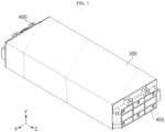
- FIG. 1 is a perspective view showing a battery module according to an embodiment of the present disclosure.
- FIG. 2 an exploded view showing some components of a battery module according to an embodiment of the present disclosure.
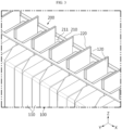
- FIG. 3 is a view showing a partial configuration of a battery module according to an embodiment of the present disclosure.
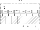
- FIG. 4 is a side view showing a partial configuration of the battery module of FIG. 3 .
- FIG. 4 shows a cross-sectional view of the bus bar 200 only, and schematically illustrates the body 110 of the battery cell 100.
- the battery module may be configured to include a plurality of battery cells 100 and a bus bar 200.
- the battery module may include a frame 300 providing an internal space 301.
- the frame 300 may have a shape with open front and rear sides.
- the end cover 400 may be provided on the front and rear sides of the frame 300.
- the end cover 400 may be coupled to the open portion of the frame 300. In this case, the frame 300 and the end cover 400 may be coupled by welding.
- the battery module may be referred to as a cell assembly or battery pack.
- the battery module according to an embodiment of the present disclosure further includes components such as a BMS, a bus bar assembly, a case, a relay, a current sensor, and the like, it may be referred to as a battery pack.
- the battery cell 100 may be provided in plurality.
- Each battery cell 100 may include a body 110 and an electrode lead 120 extending or protruding from the body 110.
- Each of the plurality of battery cells 100 may have at least one electrode lead 120 protruding from the body 110 toward the front side or in the +Z-axis direction.
- each of the plurality of battery cells 100 may have at least one electrode lead 120 protruding from the body 110 toward the rear side or in the -Z-axis direction.
- the plurality of battery cells 100 may be stacked in the left-right direction or the X-axis direction.
- the battery cell 100 may be accommodated inside the frame 300.
- the plurality of battery cells 100 may be pouch-type secondary batteries.
- the pouch-type secondary battery may be configured in a form where an electrode assembly and an electrolyte are accommodated inside a pouch case.
- the pouch case may be configured to seal the edges of two pouches in a state where the electrode assembly and the electrolyte are accommodated.
- the pouch-type secondary battery may be configured in a form where a storage portion is located at the center and a sealing portion surrounds the periphery.
- the pouch-type secondary battery may be configured in a square shape having four edges, and three or four of the four edges may be sealed.
- the bus bar 200 may be electrically connected to the electrode lead 120.
- Each of the electrode leads 120 of the plurality of battery cells 100 may be physically and/or electrically connected to the bus bar 200. According to the connection type of the bus bar 200 and the electrode lead 120, the plurality of battery cells 100 may be electrically connected in series or in parallel.
- the bus bar 200 may extend in the left-right direction. In addition, the longitudinal direction of the bus bar 200 may be perpendicular to the direction in which the electrode lead 120 protrudes. Also, the bus bar 200 may be located between the end cover 400 and the plurality of battery cells 100. In addition, the bus bar 200 may be accommodated in the space formed by the frame 300 and the end cover 400.
- the bus bar 200 may be configured to include a body portion 210 and a junction portion 220.
- the body portion 210 may be configured in a bar and/or plate shape. As the number of battery cells 100 connected to the bus bar 200 increases, the body portion 210 may be configured to extend long.
- the body portion 210 may be made of a metal material.
- the junction portion 220 may be configured in a form where at least a portion of the body portion 210 is bent. Alternatively, the junction portion 220 may be configured to extend or protrude from the body portion 210. The junction portion 220 may be physically and/or electrically connected to the electrode lead 120. For example, referring to FIG. 3 , the junction portion 220 may be bent toward the front side or in the +Z-axis direction. The junction portion 220 may be positioned to face the electrode lead 120.
- the junction portion 220 is formed by bending, so that the electrode lead 120 may be physically and/or electrically connected to the junction portion without bending or folding. As a result, pulling or stress applied to the electrode lead 120 may be minimized. Also, damage to or disconnection of the electrode lead 120 may be prevented.
- the electrode lead 120 and the tabs of the battery cell 100 may be connected, attached, fixed, or coupled horizontally. That is, the electrode tab and the electrode lead 120 are coupled through surface contact inside the battery cell 100, and this coupling portion may be maintained flat without being bent. Therefore, the possibility of disconnection of or damage to the battery cell 100 may be reduced.
- tab pulling of the electrode lead 120 may be minimized even if the battery cell 100 swells in the left-right direction.
- junction portion 220 is formed by bending the body portion 210, manufacturing of the bus bar may be facilitated, and manufacturing time and cost may be reduced. Therefore, the productivity of bus bars and battery modules including the same may be improved.
- the electrode lead 120 and the junction portion 220 of the battery module may be configured to be coupled by welding.
- the electrode lead 120 and the junction portion 220 may be welded and coupled in a lead joint J method.
- the electrode lead 120 and the junction portion 220 are coupled by welding, and thus components or additional processes for coupling may be omitted. As a result, the process may be simplified compared to other coupling methods.
- welding may be performed in a state where the electrode lead 120 faces the junction portion 220 without being bent, thereby improving weldability.
- the junction portion 220 of the battery module according to an embodiment of the present disclosure may be formed in plurality to correspond one-to-one to the electrode lead 120.
- each electrode lead 120 may be coupled to one junction portion 200.
- each electrode lead 120 may be configured to have the same length in the front-rear direction or the same length in the Z-axis direction. That is, the entire battery cell 100 included in the battery module according to the present disclosure may have the same length of the electrode leads 120 protruding outward from the body 110.
- the arrangement spacing of the plurality of battery cells 100 and the arrangement spacing of the plurality of junction portions 200 may be configured to be the same.
- a plurality of electrode leads 120 form one welded joint J and are connected to the bus bar 200.
- the degree of freedom in welding is limited depending on the metal material composition of the electrode lead 120.
- the arrangement order of the electrode leads 120 may be limited to ensure weldability.
- the arrangement order of the plurality of battery cells 100 should be limited or the electrode leads 120 should be produced with different lengths.
- one junction portion 220 and one electrode lead 120 may be coupled by one joint J, thereby improving weldability.
- the electrode leads 120 of each battery cell 100 may be configured to have the same shape or the same length, thereby improving productivity of the battery module.
- the electrode lead 120 of the battery module may be configured to have a flat shape.
- the electrode lead 120 may be configured to have an overall flat shape. That is, the electrode lead 120 may be configured in a planar shape without bending or folding as a whole.
- each of the plurality of electrode leads 120 may have a flat shape and/or a planar shape.
- the electrode lead 120 extends outward from the body 110 of the battery cell 100, but may extend in a straight line in parallel to the Z-axis direction without being bent.
- a plurality of electrode leads 120 form one welded joint and are connected to the bus bar 200.
- at least a portion of the plurality of electrode leads 120 may be bent, and the electrode leads 120 may be damaged due to bending.
- the electrode lead 120 may have an overall flat shape without bending or folding, thereby preventing damage to or disconnection of the electrode lead 120.
- the process of bending the electrode lead 120 may be omitted, thereby improving productivity of the battery module.
- bus bar 200 may be referred to as a bending-free bus bar 200 in the sense that the electrode lead 120 may be configured not to be bent for welding.
- the electrode lead 120 and the junction portion 220 of the battery module may be configured to be in surface contact.
- the junction portion 220 may be formed in a flat shape by bending at least a portion of the body portion 210 having a bar or plate shape.
- the junction portion 220 and the electrode lead 120 may be physically and/or electrically connected, and may be in surface contact.
- the contact area or coupling area between the junction portion 220 and the electrode lead 120 may be increased, thereby preventing assembly defects or welding defects due to deviations in length of the electrode lead 120.
- the contact area between the junction portion 220 and the electrode lead 120 may be stably secured above a certain level, thereby effectively reducing electrical resistance and the resulting power loss and heat generation.
- FIG. 5 is a view showing a partial configuration of a battery module according to another embodiment of the present disclosure.
- FIG. 6 is a side view showing a partial configuration of the battery module of FIG. 5 .
- FIG. 6 shows a cross-sectional view of the bus bar 200 only, and schematically illustrates the body 110 of the battery cell 100.
- the junction portion 220 of the battery module according to an embodiment of the present disclosure may extend in the front-rear direction.
- the junction portion 220 may extend toward the front side or in the +Z-axis direction according to the bending direction. Alternatively, the junction portion 220 may extend toward the rear side or in the -Z-axis direction according to the bending direction. Alternatively, at least a portion of the junction portion 220 may extend toward the front side or in the +Z-axis direction, and the remainder may extend toward the rear side or in the -Z-axis direction.
- the length of the electrode lead 120 may be configured to be shorter than when the junction portion 220 extends toward the front side or in the +Z-axis direction.
- the junction portion 220 may be configured to be bent approximately perpendicular to the body portion 210.
- the junction portion 220 may be configured parallel to the X-Z plane so as to be perpendicular to the body portion 210.
- junction portion 220 may be configured to be parallel to the longitudinal direction of the battery cell 100.
- the battery cell 100 can be said to be formed long in the Z-axis direction, and the junction portion 220 of the bus bar 200 can also be said to be formed to extend long in the Z-axis direction.
- the electrode lead 120 may selectively extend to the front side or the rear side, thereby increasing the degree of freedom in designing the battery module.
- the electrode lead 120 may continue to maintain a straight shape not only in the portion protruding outward from the sealing portion of the body 110, but also in the portion welded to the junction portion 220 of the bus bar 200.
- the configuration in which the electrode lead 120 protrudes toward the front of the bus bar 200 may be omitted by bending the electrode lead 120 backward.
- the electrode lead 120 and the junction portion 220 may be located inside the bus bar 200 and may be more stably protected from the outside.
- the degree of freedom in designing space in front of the bus bar 200 may be increased.
- the electrode lead 120 may be selectively welded to any one of both surfaces of the rearwardly bent junction portion 220. In this case, the electrode lead 120 may be welded to any one of both surfaces of the junction portion 220 so that bending may be minimized.
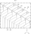
- FIG. 7 is a perspective view showing a bus bar 200 of a battery module according to an embodiment of the present disclosure.
- FIG. 8 is a perspective view showing a bus bar 200 of a battery module according to another embodiment of the present disclosure.
- FIG. 9 is a perspective view showing a bus bar 200 of a battery module according to still another embodiment of the present disclosure.
- the junction portion 220 according to an embodiment of the present disclosure may be configured to be integrally formed with the body portion 210.
- the productivity of the battery module may be improved. Also, in this case, there is no need for a structure or a fastening member for coupling the junction portion 220 to the body portion 210, so that the coupling force between the junction portion 220 and the body portion 210 may be stably secured. In addition, contact resistance between the junction portion 220 and the body portion 210 may be eliminated or reduced.
- the junction portion 220 of the bus bar 200 of the battery module may be configured such that at least a portion of the body portion 210 is cut and the cut portion is formed by bending.
- the body portion 210 may be cut.
- the cut line C may penetrate the body portion 210.
- the cut line C may form three of the four sides of a rectangle.
- the width W of the cut portion may be formed to be equal to or greater than the width of the electrode lead 120.
- the cut portion of the body portion 210 may be bent toward the front side or in the +Z-axis direction.
- the cut portion of the body portion 210 may be bent toward the rear side or in the -Z-axis direction.
- the cut portion of the body portion 210 may be bent to form the junction portion 220.
- the junction portion 220 may be bent or extended in a direction orthogonal to the body portion 210.
- the junction portion 220 does not require separate component processing and may be formed in a relatively simple process. As a result, the productivity of the battery module may be improved.
- the bus bar 200 of the battery module may include a hole 211 adjacent to the junction portion 220 and penetrating the body portion 210, and the diameters D2, D4 of the junction portion 220 may be configured to be smaller than the diameters D1, D3 of the hole 211.
- the hole 211 may be formed by bending the junction portion 220.
- the hole 211 may be formed in a rectangular shape.
- the diameters D 1, D3 of the hole 211 may mean the maximum diameters D1, D3 of the hole 211.
- the diameters D2, D4 of the junction portion 220 may mean the maximum diameters D2, D4 of the junction portion.
- the junction portion 220 may mean a flat plate portion.
- the diameters D2, D4 of the junction portion 220 may be configured to be smaller than the diameters D1, D3 of the hole 211.
- the diameters D2, D4 of the junction portion 220 may be formed as small as the width of the cut line C in the diameters D1, D3 of the hole 211.
- the junction portion 220 when the bent junction portion 220 is flattened, the junction portion 220 may be entirely accommodated in the hole 211.
- the junction portion 220 and the hole 211 may be formed at the same time.
- the manufacturing process of the bus bar 200 may be simplified and the productivity of the battery module may be improved.
- the bus bar 200 of the battery module may include a hole 211 adjacent to the junction portion 220 and penetrating the body portion 210, and the electrode lead 120 may be configured to pass through the hole 211.
- At least a portion of the electrode lead 120 may pass through the hole 211 and be coupled to the junction portion 220.
- the electrode lead 120 and the junction portion 220 may be referred to as a lead insert joint J structure.
- the junction portion 220 and the hole 211 may be formed at the same time.
- the manufacturing process of the bus bar 200 may be simplified and the productivity of the battery module may be improved.
- FIG. 10 is a perspective view showing a battery module according to another embodiment of the present disclosure.
- FIG. 11 is a perspective view showing a battery module according to still another embodiment of the present disclosure.
- FIGS. 10 and 11 show a cross-sectional view of the bus bar 200 only, and schematically illustrate the body 110 of the battery cell 100.
- at least a portion of the bus bar 200 of the battery module according to an embodiment of the present disclosure may be composed of different metal layers M1, M2.
- the bus bar 200 may be made of a clad metal material.
- the bus bar 200 may be composed of two metal layers M1, M2.
- the two metal layers M1, M2 may be made of different materials.
- the bus bar 200 may be configured to include a metal layer made of the same material as the metal material of the negative electrode lead 120 and a metal layer made of the same material as the metal material of the positive electrode lead 120.
- one surface of the bus bar 200 may be made of aluminum, and the other surface of the bus bar may be made of copper.
- the electrode lead 120 may be welded to the metal layers M1, M2 of the bus bar 200 having the same metal material as that of the electrode lead 120.
- the weldability of the bus bar 200 and the electrode lead 120 may be improved.
- the degree of freedom in arranging the plurality of battery cells 100 may be increased.
- junction portion 220 of the battery module may be composed of different metal layers M1, M2.
- the body portion 210 and the junction portion 220 of the bus bar 200 may be integrally formed, and the body portion 210 and the junction portion 220 may be made of the same clad metal material.
- the junction portion 220 may be bent toward the rear side or in the -Z-axis direction.
- the right side of the junction portion 220 may be composed of a first metal layer M1
- the left side of the junction portion 220 may be composed of a second metal layer M2.
- the electrode lead 120 may be selectively welded to the first metal layer M1 or the second metal layer M2 of the junction portion 220.
- the electrode lead 120 may be welded to the first metal layer M1.
- the second metal layer M2 is made of copper and the electrode lead 120 is made of copper
- the electrode lead 120 may be welded to the second metal layer M2.
- the electrode lead 120 may be selectively welded to the junction portion 220 having the same metal material as that of the electrode lead 120. As a result, the weldability of the bus bar 200 and the electrode lead 120 may be improved.
- a portion of the junction portion 220 may be bent toward the rear side or in the -Z-axis direction, and the remainder of the junction portion 220 may be bent toward the front side or in the +Z-axis direction.
- the electrode lead 120 may be selectively welded to the junction portion 220 bent toward the front side or in the +Z-axis direction or to the junction portion 220 bent toward the rear side or in the -Z-axis direction. That is, the junction portion 220 may be bent in either the +Z-axis direction or the -Z-axis direction depending on the material of the electrode lead 120 to be welded.
- junction portions 220 bent in opposite directions with respect to the body portion 210 may be provided in one bus bar 200.
- the electrode lead 120 may be welded to the right side of the junction portion 220 bent toward the front side or in the +Z-axis direction or to the second metal layer M2.
- the metal material of the electrode lead 120 and the metal material of the second metal layer M2 may be the same material.
- the electrode lead 120 may be welded to the right side of the junction portion 220 bent toward the rear side or in the -Z-axis direction or to the first metal layer M1.
- the metal material of the electrode lead 120 and the metal material of the first metal layer M1 may be the same material.
- the length of the electrode lead 120 of the battery cell 100 welded to the junction portion 220 bent toward the front side or in the +Z-axis direction may be configured to be longer than the length of the electrode lead 120 of the battery cell 100 welded to the junction portion 220 bent toward the rear side or in the -Z-axis direction.
- the electrode lead 120 may be selectively welded to the junction portion 220 having the same metal material as that of the electrode lead 120. As a result, the weldability of the bus bar 200 and the electrode lead 120 may be improved.
- the degree of freedom in the stacking order of the battery cells 100 may be increased.
- the bending direction of the junction portion 220 may be selectively configured to correspond to the stacking order of the battery cells 100.
- the battery pack according to the present disclosure may include the battery module according to the present disclosure described above. Also, the battery pack according to the present disclosure may further include various other components in addition to the battery module according to the present disclosure described above, for example, components of a battery pack known at the time of filing of the present disclosure, such as a BMS, a bus bar, a pack case, a relay, a current sensor, or the like.
- the vehicle according to the present disclosure may include the battery module according to the present disclosure described above.
- the battery module according to the present disclosure may be applied to vehicles such as electric vehicles or hybrid vehicles.
- the vehicle according to the present disclosure may further include various other components included in the vehicle in addition to the battery module, such as a vehicle body, a motor, a control device like an electronic control unit (ECU), or the like.
- ECU electronice control unit
- the energy storage system (ESS) according to the present disclosure may include the battery module according to the present disclosure described above.
- the energy storage system according to the present disclosure may further include other components included in the energy storage system in addition to the battery module, such as a sensor for detecting the state of the battery module, a firefighting module for controlling thermal events, a DC part, an AC part, a BSC part, or the like.
Landscapes
- Chemical & Material Sciences (AREA)
- Chemical Kinetics & Catalysis (AREA)
- Electrochemistry (AREA)
- General Chemical & Material Sciences (AREA)
- Engineering & Computer Science (AREA)
- Aviation & Aerospace Engineering (AREA)
- Connection Of Batteries Or Terminals (AREA)
- Battery Mounting, Suspending (AREA)
Applications Claiming Priority (3)
| Application Number | Priority Date | Filing Date | Title |
|---|---|---|---|
| KR20220084676 | 2022-07-08 | ||
| KR1020230031777A KR20240007581A (ko) | 2022-07-08 | 2023-03-10 | 배터리 모듈 |
| PCT/KR2023/009709 WO2024010428A1 (ko) | 2022-07-08 | 2023-07-07 | 배터리 모듈 |
Publications (2)
| Publication Number | Publication Date |
|---|---|
| EP4391202A1 true EP4391202A1 (de) | 2024-06-26 |
| EP4391202A4 EP4391202A4 (de) | 2025-03-12 |
Family
ID=89453807
Family Applications (1)
| Application Number | Title | Priority Date | Filing Date |
|---|---|---|---|
| EP23835894.9A Pending EP4391202A4 (de) | 2022-07-08 | 2023-07-07 | Batteriemodul |
Country Status (4)
| Country | Link |
|---|---|
| US (1) | US20250007057A1 (de) |
| EP (1) | EP4391202A4 (de) |
| JP (1) | JP2024538150A (de) |
| WO (1) | WO2024010428A1 (de) |
Family Cites Families (18)
| Publication number | Priority date | Publication date | Assignee | Title |
|---|---|---|---|---|
| JP2568023B2 (ja) * | 1993-01-18 | 1996-12-25 | 日本碍子株式会社 | 単電池の接続端子及び接続構造 |
| US5404282A (en) * | 1993-09-17 | 1995-04-04 | Hewlett-Packard Company | Multiple light emitting diode module |
| EP2894695A3 (de) * | 2013-11-05 | 2015-12-02 | Tyco Electronics Amp Korea Ltd. | Batteriezellenverbindungsplatine |
| KR102263304B1 (ko) * | 2013-11-05 | 2021-06-15 | 타이코에이엠피 주식회사 | 배터리 셀 연결보드 |
| KR101565115B1 (ko) * | 2014-03-31 | 2015-11-02 | (주)탑전지 | 배터리 팩 및 그 제조 방법 |
| KR101736377B1 (ko) * | 2014-06-09 | 2017-05-16 | 주식회사 엘지화학 | 배터리 모듈 및 이를 포함하는 배터리 팩 |
| JP2017195056A (ja) * | 2016-04-19 | 2017-10-26 | 株式会社東芝 | コネクタ構造、バスバー部材及び電池モジュール |
| CN206059494U (zh) * | 2016-08-23 | 2017-03-29 | 多氟多(焦作)新能源科技有限公司 | 一种汇流排、电池模块及电池包 |
| KR102117859B1 (ko) * | 2016-12-23 | 2020-06-02 | 에스케이이노베이션 주식회사 | 배터리 모듈 |
| CN207781712U (zh) * | 2017-05-31 | 2018-08-28 | 李树成 | 一种新能源汽车及其电池汇流排结构 |
| JP7054442B2 (ja) * | 2018-03-06 | 2022-04-14 | トヨタ自動車株式会社 | 組電池および組電池の製造方法 |
| CN208433451U (zh) * | 2018-07-31 | 2019-01-25 | 河南森源重工有限公司 | 一种汇流板及电池模组 |
| EP3657570A1 (de) * | 2018-11-26 | 2020-05-27 | Aptiv Technologies Limited | Batteriemodul |
| CN211428258U (zh) * | 2019-12-30 | 2020-09-04 | 合肥国轩高科动力能源有限公司 | 一种锂离子电池的外短路保护装置 |
| JP2022014957A (ja) * | 2020-07-08 | 2022-01-21 | 株式会社オートネットワーク技術研究所 | 電池配線モジュール |
| KR20220043373A (ko) * | 2020-09-29 | 2022-04-05 | 에이치그린파워 주식회사 | 배터리 모듈의 리드 연결 구조 및 방법 |
| KR102543412B1 (ko) | 2020-12-14 | 2023-06-14 | (주)아이벡스메디칼시스템즈 | 외이와 중이간 압력 평형 상태를 감지하는 고압산소챔버의 자동 압력 제어 방법 |
| JP7712148B2 (ja) | 2021-08-27 | 2025-07-23 | 株式会社ディスコ | 基板の分割方法 |
-
2023
- 2023-07-07 EP EP23835894.9A patent/EP4391202A4/de active Pending
- 2023-07-07 WO PCT/KR2023/009709 patent/WO2024010428A1/ko not_active Ceased
- 2023-07-07 US US18/711,295 patent/US20250007057A1/en active Pending
- 2023-07-07 JP JP2024522657A patent/JP2024538150A/ja active Pending
Also Published As
| Publication number | Publication date |
|---|---|
| JP2024538150A (ja) | 2024-10-18 |
| EP4391202A4 (de) | 2025-03-12 |
| WO2024010428A1 (ko) | 2024-01-11 |
| US20250007057A1 (en) | 2025-01-02 |
Similar Documents
| Publication | Publication Date | Title |
|---|---|---|
| EP3637501B1 (de) | Sammelschienenanordnung zur verbindung von elektrodendrähten und batteriemodul damit | |
| EP3340338B1 (de) | Batteriemodul | |
| CN106133948B (zh) | 电池模块和包括该电池模块的电池组 | |
| EP3761393A1 (de) | Batteriemodul mit innenabdeckung | |
| CN210120177U (zh) | 电池模块、包含电池模块的电池组和包含电池组的车辆 | |
| EP3926734B1 (de) | Batteriemodul und batteriepack damit | |
| EP3971925B1 (de) | Batteriemodul und batteriepack damit | |
| JP5537409B2 (ja) | 電池モジュールの製造方法 | |
| JP5591087B2 (ja) | 電池モジュール及びプレート組立体 | |
| KR102693863B1 (ko) | 내진동성이 향상된 배터리 팩 | |
| EP4435958A1 (de) | Batteriemodul und batteriepack damit | |
| CN116250148A (zh) | 电池模块、电池组和车辆 | |
| US20250105413A1 (en) | Battery submodule | |
| EP4254626A1 (de) | Batteriepack und vorrichtung damit | |
| KR20240007581A (ko) | 배터리 모듈 | |
| US20250007057A1 (en) | Battery module | |
| US20240039125A1 (en) | Battery module and battery pack including the same | |
| KR20240081284A (ko) | 배터리 모듈, 그리고 이를 포함하는 배터리 팩 및 자동차 | |
| CN117957711A (zh) | 电池模块 | |
| EP4579939A1 (de) | Batteriemodul | |
| KR20210130444A (ko) | 전지 모듈 및 이를 포함하는 전지팩 | |
| US20240413449A1 (en) | Battery pack | |
| KR102523946B1 (ko) | 버스바 프레임 및 이를 갖는 배터리 모듈 | |
| EP4362206A1 (de) | Batteriemodul, batteriepack und fahrzeug damit | |
| US20240413469A1 (en) | Battery module and battery pack |
Legal Events
| Date | Code | Title | Description |
|---|---|---|---|
| STAA | Information on the status of an ep patent application or granted ep patent |
Free format text: STATUS: THE INTERNATIONAL PUBLICATION HAS BEEN MADE |
|
| PUAI | Public reference made under article 153(3) epc to a published international application that has entered the european phase |
Free format text: ORIGINAL CODE: 0009012 |
|
| STAA | Information on the status of an ep patent application or granted ep patent |
Free format text: STATUS: REQUEST FOR EXAMINATION WAS MADE |
|
| 17P | Request for examination filed |
Effective date: 20240320 |
|
| AK | Designated contracting states |
Kind code of ref document: A1 Designated state(s): AL AT BE BG CH CY CZ DE DK EE ES FI FR GB GR HR HU IE IS IT LI LT LU LV MC ME MK MT NL NO PL PT RO RS SE SI SK SM TR |
|
| A4 | Supplementary search report drawn up and despatched |
Effective date: 20250206 |
|
| RIC1 | Information provided on ipc code assigned before grant |
Ipc: H01M 50/553 20210101ALI20250131BHEP Ipc: H01M 50/548 20210101ALI20250131BHEP Ipc: H01M 50/507 20210101ALI20250131BHEP Ipc: H01M 50/505 20210101ALI20250131BHEP Ipc: H01M 50/50 20210101ALI20250131BHEP Ipc: H01M 50/178 20210101ALI20250131BHEP Ipc: H01M 50/584 20210101ALI20250131BHEP Ipc: H01M 50/211 20210101ALI20250131BHEP Ipc: H01M 50/251 20210101ALI20250131BHEP Ipc: H01M 50/249 20210101ALI20250131BHEP Ipc: H01M 50/557 20210101ALI20250131BHEP Ipc: H01M 50/521 20210101ALI20250131BHEP Ipc: H01M 50/533 20210101ALI20250131BHEP Ipc: H01M 50/503 20210101ALI20250131BHEP Ipc: H01M 50/516 20210101AFI20250131BHEP |
|
| STAA | Information on the status of an ep patent application or granted ep patent |
Free format text: STATUS: EXAMINATION IS IN PROGRESS |
|
| DAV | Request for validation of the european patent (deleted) | ||
| DAX | Request for extension of the european patent (deleted) | ||
| 17Q | First examination report despatched |
Effective date: 20250925 |