EP4385933B1 - Verfahren zum schutz eines hebezeuges gegen überlast und vorrichtung zur durchführung des verfahrens - Google Patents
Verfahren zum schutz eines hebezeuges gegen überlast und vorrichtung zur durchführung des verfahrens Download PDFInfo
- Publication number
- EP4385933B1 EP4385933B1 EP23199929.3A EP23199929A EP4385933B1 EP 4385933 B1 EP4385933 B1 EP 4385933B1 EP 23199929 A EP23199929 A EP 23199929A EP 4385933 B1 EP4385933 B1 EP 4385933B1
- Authority
- EP
- European Patent Office
- Prior art keywords
- drum
- lifting
- threshold
- overload
- rotation
- Prior art date
- Legal status (The legal status is an assumption and is not a legal conclusion. Google has not performed a legal analysis and makes no representation as to the accuracy of the status listed.)
- Active
Links
Images


Classifications
-
- B—PERFORMING OPERATIONS; TRANSPORTING
- B66—HOISTING; LIFTING; HAULING
- B66D—CAPSTANS; WINCHES; TACKLES, e.g. PULLEY BLOCKS; HOISTS
- B66D1/00—Rope, cable, or chain winding mechanisms; Capstans
- B66D1/54—Safety gear
- B66D1/58—Safety gear responsive to excess of load
-
- B—PERFORMING OPERATIONS; TRANSPORTING
- B66—HOISTING; LIFTING; HAULING
- B66D—CAPSTANS; WINCHES; TACKLES, e.g. PULLEY BLOCKS; HOISTS
- B66D1/00—Rope, cable, or chain winding mechanisms; Capstans
- B66D1/28—Other constructional details
- B66D1/40—Control devices
- B66D1/48—Control devices automatic
-
- B—PERFORMING OPERATIONS; TRANSPORTING
- B64—AIRCRAFT; AVIATION; COSMONAUTICS
- B64D—EQUIPMENT FOR FITTING IN OR TO AIRCRAFT; FLIGHT SUITS; PARACHUTES; ARRANGEMENT OR MOUNTING OF POWER PLANTS OR PROPULSION TRANSMISSIONS IN AIRCRAFT
- B64D1/00—Dropping, ejecting, releasing or receiving articles, liquids, or the like, in flight
- B64D1/22—Taking-up articles from earth's surface
Definitions
- the present invention relates to the technical field of lifting devices, and more particularly winches, and even more specifically winches mounted on aircraft and in particular helicopters.
- a winch is traditionally made up of at least one drum, also called a lifting drum, associated with a kinematic system ensuring the rotation of the drum on itself, in order to allow the winding and unwinding of a lifting cable, at the end of which a load is fixed.
- Such safety devices are known which induce, in the event of detection of exceeding a limit load, the unwinding of the cable.
- These devices traditionally use a friction clutch system, consisting of one or more friction discs and a spring, said spring being calibrated to a value corresponding to the limit mass or limit load beyond which it is desired to cause the cable to unwind.
- WO 2008/088220 A1 discloses a method for protecting a lifting member against an overload, the lifting member comprising a lifting drum on which is wound a cable at the end of which is fixed a load, said lifting drum being mechanically linked to a motor capable of ensuring its rotation, the mechanical connection comprising a clutch or equivalent device, said method comprising:- a first operating threshold, the exceeding of which causes the lifting drum to operate in freewheel mode relative to the kinematic chain emanating from the motor.
- One of the objectives of the present invention is to propose a more reliable system in terms of safety, in terms of adjustment of the trigger threshold in the event of an overload and also in terms of modularity of said trigger threshold of the system depending on the operating conditions of the winch and, consequently, of the helicopter in which said winch is mounted.
- the invention firstly concerns a method for protecting a lifting member against an overload, the lifting member comprising a lifting drum on which is wound a cable at the end of which a load is fixed, said drum being mechanically linked to an electric motor, in particular by a clutch or equivalent device.
- the method consists first of all in allowing free rotation of the drum according to the freewheel principle after the triggering of the first threshold, that is to say, when a torque greater than a determined value is exerted on the drum by the cable, then, after freewheeling of a part of the cable due to the overload thus exerted, in attempting to slow down or even stop this free rotation of the drum by the effect of the second threshold, in order to thus oppose the complete unwinding of the cable in the event of the occurrence of an overload.
- the method consists, as a corollary, in attempting to re-couple the lifting drum to the kinematic chain, and alternatively, when the attempt to stop this free rotation is not possible due, for example, to the end of the cable being caught in a fixed point, in giving the operator of the lifting device sufficient time to possibly take the decision to cause the cutting of said cable.
- the method consists, after exerting a torque on the lifting drum greater than or equal to said first threshold, and when slowing down or stopping the rotation of the drum is not possible, in particular due to the persistence of said torque exerted on the drum beyond said first threshold, in generating an automatic re-engagement of the clutch or equivalent device according to a determined periodicity, and in this case less than or equal to 5 seconds, capable of mechanically re-coupling the lifting drum and the electric motor.
- the torque remains greater than said first threshold, the free rotation of the drum relative to the drive train is again activated.
- the invention also relates to a method for protecting a lifting member against an overload, in which the lifting member consists of a capstan drum associated with a cable storage drum.
- the method of the invention in such a configuration, is identical to that previously described, the storage drum then being provided with brakes, capable of ensuring the minimum residual tension between the storage drum and the capstan in order to allow the correct operation of the lifting member.
- the invention finally relates to a device for protecting the lifting member against an overload in order to allow the operation of said lifting member according to the method set out above.
- the clutch or equivalent device is provided with elements capable of ensuring the free rotation of the drum relative to the drive shaft as soon as the torque exerted by the lifting cable on the drum is greater than a predetermined threshold value - corresponding to the first threshold; the lifting member is further provided with means capable of causing the slowing down, or even stopping, of the rotation of the lifting drum after being put into free rotation of the latter, so as to allow the recoupling of the rotating shaft of the motor on the lifting drum.
- these means consist of brakes, acting on the lifting drum, and whose maximum braking capacities correspond to said second threshold.
- the clutch or equivalent device consists of a removable cartridge, called an overload cartridge, capable of being coupled respectively to the drive shaft and to the lifting drum.
- This cartridge consists of a bell receiving two rings independent of each other. These rings cooperate with each other by means of a plurality of balls received in housings of adapted shape of one of said rings and projecting from said housings in order to also be received in through-holes arranged within the other ring, springs, advantageously arranged within a cage, exerting pressure on said balls, the assembly thus defining said first threshold.
- One of said rings is integral with the bell, itself mechanically connected to the drive shaft, and the other ring is integral with a means capable of rotating the lifting drum.
- the housings provided within one of the crowns and intended to receive the balls communicate with an internal annular groove provided within said crown, of lesser depth than said housings, this communication being achieved by means of non-radial ramps.
- the device of the invention also comprises additional braking means, in this case consisting of friction discs, capable of cooperating with a member integral with said crown mechanically linked to the lifting drum, the upper limit of action of said brakes constituting said second threshold.
- additional braking means in this case consisting of friction discs, capable of cooperating with a member integral with said crown mechanically linked to the lifting drum, the upper limit of action of said brakes constituting said second threshold.
- the device of the invention is integrated within a winch, and in this case, a capstan winch. It must however be understood that in the spirit of the invention, the device is capable of operating with a conventional winch, that is to say one whose lifting drum also ensures storage.
- the lifting assembly (1) consists of a drum (3) called a capstan, ensuring the winding and unwinding of a cable (4), at the end of which a load (5) is fixed.
- the drum (3) is rotated under the action of an electric motor (6). If in the example described, only one capstan drum is illustrated, the invention also aims at the implementation of a capstan comprising two drums mounted parallel to each other, each of said drums receiving only a single layer of cable turns at its periphery.
- a storage drum (7) on which are stored several thicknesses of turns of the cable coming from the capstan drum(s) (3), said storage drum (7) being rotated by an electric motor (8).
- FIG. 1 illustrates, as already indicated, the normal operation of the lifting member, that is to say in the absence of any overload.
- the two coupling members (9) and (10) are schematically in contact with each other, in other words, that there is coupling between the kinematic chain and the capstan drum (3).
- the service brake (not shown) associated with the electric motor (6) allows the lifting member to be subjected to a payload greater than the nominal load determined by the manufacturer, but obviously lower than said first threshold.
- FIG. 2 illustrates an intermediate operating mode, according to which an overload is detected, always lower than said first threshold, but nevertheless higher than the payload mentioned above.
- This operating mode is deemed to occur after the detection of an overload higher than said first threshold, with the aim of allowing, as will be described later, the rearming or re-coupling of the kinematic chain on the capstan drum (3).
- FIG 3 illustrates the mode of operation according to which an overload greater than said first threshold is detected.
- an overload may, for example, result from the fall of an operator connected to the cable (4), or from the grip of the end of said cable, whether or not equipped with a load, in a fixed point, such as a pylon, tree, etc.
- the capstan drum (3) can rotate freely, and for this purpose, the kinematic chain connecting the motor (6) to the capstan (3) is uncoupled.
- This uncoupling results in an axial displacement of one of the members coupling (9, 10), and in this case of the member (9), which, due to this movement, activates the switch (11).
- activating the switch (11) also causes the power supply to the electric motor (8) to be stopped, in addition to closing the ratchet wheel (14).
- braking members (15) typically consisting of friction discs, cooperate with the storage drum (7), to limit its free unwinding.
- the capstan (3) If an overload is detected on the capstan (3) greater than said first threshold ( figure 3 ), the capstan (3) is not only decoupled from the drive motor (6), but then operates in relation to the latter like a freewheel, allowing the free unwinding of the cable as required.
- the brakes (15) acting on the storage drum (7) exerting a braking action much lower than the overload in question, are not such as to affect the free rotation of said storage drum, and therefore, as a corollary, the free unwinding of the cable.
- the lifting member of the invention is thus designed so that the free rotation of the capstan (3) following the detection of an overload greater than said first threshold is limited in time.
- This free rotation in fact results in the absence or near absence of torque exerted on the lifting drum or the capstan (3).
- an attempt is made, after this drastic reduction in torque, to slow down or even stop this free rotation of the drum, in order to thus oppose the complete unwinding of the cable, and alternatively, when the attempt to stop this free rotation is not possible due, for example, to the gripping the end of the cable at a fixed point, to allow the operator to cut the cable.
- the brakes (12) associated with the lifting drum or the capstan define a second threshold, and attempt to achieve the desired slowing down or stopping of said lifting drum.
- the device of the invention causes the recoupling of the members (9, 10), in order to engage the lifting drum on the motor (6), and thus resume normal operation of the lifting member. If, however, the event causing the overload persists, said members (9, 10) are again uncoupled, again causing the free rotation of the lifting drum or capstan.
- the lifting member Typically, if the rotation speed of the motor becomes greater than or equal to the cable unwinding speed, following a successful attempt to re-couple the two coupling members (9, 10), the lifting member returns to its normal operation.
- this attempt at re-coupling fails, due to the torque exerted on the capstan (3) remaining above the first threshold, for example due to the end of the cable being caught in a fixed point such as a pylon or tree, the freewheeling continues, and after a new unsuccessful attempt at re-coupling, the operator can then decide to cut the cable, in particular so as not to impact the integrity of the helicopter in which the lifting device is mounted.
- the curve in regular broken lines illustrates the application of a sudden or abrupt overload, typically resulting from the fall of an operator attached to the free end of the cable, or following a slack cable which is followed by a sudden tension of said cable, and in any case exceeding said first threshold.
- the device of the invention almost immediately induces the operation of the capstan (3) in freewheel mode, resulting on said curve by an inflection and the lowering of the value of the detected load until reaching the level of said second threshold, corresponding to the activation of the brakes (12) on the capstan.
- the curve in broken and irregular lines illustrates a progressive overload, likely to result from the end of the cable being caught in a pylon, tree, etc. If this occurs, when this load reaches said second threshold, the braking system (15) attempts to brake and reduce the load then applied to the lifting drum or capstan. If this braking is sufficient, the curve returns to normal operating mode. If, however, this braking is insufficient, and the load increases further and exceeds said first threshold, we find us in the configuration described in the previous paragraph.
- FIG. 5 An overall schematic view of the overload cartridge (20), constituting one of the key elements of the device of the invention, and within which the coupling members (9, 10) intervene.
- This overload cartridge (20) is removable, in the sense that it is possible to interchange it with another cartridge provided with other characteristics, in particular in terms of overload detection thresholds. It is in fact provided with coupling means, in this case (22) on the capstan (3) and on the motor shaft emanating from the motor (6) (not shown).
- a toothed pinion (23) intended to cooperate with the braking device (12) of the lifting drum or capstan (3), and the teeth (45) of the ratchet (13), the function of which will be described later.
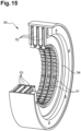
- the toothed pinion (23) is capable of meshing with a toothed crown (51) of appropriate shape and size, arranged inside the braking device (50), described in more detail in the figure 15 .
- This cartridge (20) is in fact made up of a bell (21), typically metallic, of circular cross-section, and presenting a symmetry of revolution, as can be observed on the Figures 6 and 7 .
- the bell (21) has a bottom (24), in this case openwork, from which emanates a central cylindrical projection (25) within which is housed the end of the shaft emanating from the electric motor (6) ensuring the rotation of the lifting drum or capstan (3).
- the bell has, in a position opposite the bottom (24), an opening (26), intended to allow the introduction of the various constituent elements of the device of the invention within the bell (21).
- the bottom (24) of the bell (21) is intended to receive a first annular crown (27), illustrated in detail in the figure 8
- This crown (27) is reversibly secured to the bottom of the bell by means of radial projections (28) capable of being received within through slots (29) formed within the bottom (24) in a corresponding manner, both in positioning and in dimensions.
- the other face of the first crown (27) is provided with housings (30) of generally truncated cone shape, arranged periodically in the vicinity of the periphery of said crown.
- Each of these housings (30) communicates by means of an inclined ramp (31) with an annular groove or track (32), positioned in the vicinity of the internal diameter of said crown, and of depth less than that of the housings (30).
- the housings (30) are intended to each receive a ball (33) made of a material of high hardness, and typically of steel.
- Said first crown (27) is intended to cooperate with a second crown (35), illustrated for example in the figure 9 , secured to a member (37) capable of coming onto an element of corresponding shape, to ensure the rotation of the lifting drum or capstan (3).
- FIG 12 illustrates in exploded perspective the various constituent elements of this overload cartridge.
- the two respective crowns (27, 35) intended to cooperate with each other, and whose operating principle will be described in detail later.
- the member (37) to which the second crown (35) is secured can rotate freely, subject to external constraints, around the projecting zone (25) of the bell (21), a needle bearing (38) being interposed between the two.
- the first overload trigger threshold mentioned above is ensured mechanically, by means of a plurality of springs (40), trapped in a cage defined by two opposing plates (41) and (42), coaxial with the bell (21) and the crowns (27, 35).
- One (41) of said plates of the cage comes to bear against the balls (33) (see Figures 10 and 11 ), and the other plate (42) is secured to the free upper edge of said bell by means of an annular flange (46), thereby constituting a fixed point of application of the springs (40).
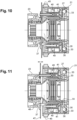
- FIG. 13 illustrates this operation.
- the balls (33) are present in the housings (30) of the first crown (27), and corollarily cooperate via the through slots (36) provided within the second crown (35) with the latter.
- Three arrows A, B and C illustrate the respective components of action of the springs (40) exerted on the balls (33), and of the cooperation between the balls (33) with the second crown (35), broken down into a tangential component and a radial component.
- the torque exerted on the capstan due to the load (5) results in a force lower in the radial direction than that exerted by the springs (40), so that the two crowns are coupled.
- the radial component resulting from said torque becomes greater in value than the action exerted by the springs (40), inducing the exit of the balls (33) from their respective truncated cone housing (30) and their movement towards the internal annular groove (32), so that due to the lesser depth of said groove (32) compared to the diameter of the balls, the latter cause the axial movement of the plate (41) and consequently of the plate (47).
- the balls (33) then present within the internal annular groove (32), then constituting a ball bearing, allow the rotation in freewheel mode of the assembly of the two crowns (27, 35) relative to the assembly (40 - 42), and in fact, the operation of the capstan (3) in freewheel mode relative to the drive shaft, and therefore the free unwinding of the cable (4).
- this braking device After the action of this braking device, which it should be recalled intervenes after detection of an overload, and therefore after free rotation of the lifting drum or capstan, the rotation speed of said capstan is slowed down, and consequently, as the torque exerted on said capstan is drastically reduced, precisely because of the free rotation, the recoupling of the crowns (27) and (35) is attempted. This attempt succeeds if the rotation speed of the drive shaft is greater than that of the lifting drum or capstan, causing, due to the shape and inclination of the through slots (36) of the second crown (35) the return of the balls (33) into their respective housing (30).
- a ratchet wheel illustrated by the reference (45) on the figures 5 And 10 - 12 , is activated when the switch (11) is itself activated, that is to say in the case of the detection of an overload greater than or equal to said first threshold.
- This ratchet is intended to stop the motor (6).
- a ratchet-type member (14) is also activated after detection of the overload by the switch (11).
- This ratchet (14) acts on the brakes (15) of the storage drum (7), in the case of a capstan winch, so that said drum can continue its rotation, in order to maintain sufficient tension in the cable strand (16) separating the capstan (3) from the storage drum (7), even when the capstan (3) is operating in freewheel mode.
- the braking device (50) is also capable of being in the form of a removable element. In doing so, by modifying the characteristics of the members which constitute it, it is possible to modify its braking characteristics, and therefore, as a corollary, said second threshold.
Landscapes
- Engineering & Computer Science (AREA)
- Mechanical Engineering (AREA)
- One-Way And Automatic Clutches, And Combinations Of Different Clutches (AREA)
- Control Of Electric Motors In General (AREA)
Claims (11)
- Verfahren zum Schutz eines Hebeorgans vor Überlastung, wobei das Hebeorgan eine Hebetrommel (3) umfasst, auf der ein Seil (4) aufgewickelt wird, an dessen Ende eine Last (5) befestigt ist, wobei die Hebetrommel (3) mechanisch mit einem Elektromotor (6) verbunden ist, der geeignet ist, ihre Drehung zu gewährleisten, wobei die mechanische Verbindung eine Kupplung oder eine gleichwertige Vorrichtung umfasst, dadurch gekennzeichnet, dass das Verfahren mindestens zwei unterschiedliche betriebliche Schwellenwerte umfasst:▪ einen ersten Schwellenwert, dessen Überschreitung zum Leerlaufbetrieb der Hebetrommel (3) in Bezug auf die kinematische Kette führt, die vom Elektromotor (6) ausgeht;▪ einen zweiten Schwellenwert, dessen Wert höher ist als der Wert der Nennlast des Hebeorgans, dessen Wert jedoch unter dem ersten Schwellenwert liegt, der die Drehung der Hebetrommel (3) abbremst und zu einem Versuch führt, die Drehung der Trommel schrittweise anzuhalten.
- Verfahren zum Schutz eines Hebeorgans vor einer Überlastung nach Anspruch 1, das bei Überschreitung des ersten Schwellenwerts außerdem einen Schritt umfasst, der darin besteht, zu versuchen, die Hebetrommel wieder an die kinematische Kette anzukoppeln, die in einer bestimmten Periodizität eingreift.
- Verfahren zum Schutz eines Hebeorgans vor Überlastung nach Anspruch 2, wobei die festgelegte Periodizität unter 5 Sekunden liegt.
- Verfahren zum Schutz eines Hebeorgans vor Überlastung, bei dem die Hebetrommel zu einem Spillwindensystem (3) gehört, das mit einer Speichertrommel (7) verbunden ist, nach einem der Ansprüche 1 bis 3, ein Verfahren, bei dem die Überschreitung des ersten Schwellenwerts zum Abbremsen der Drehung der Speichertrommel führt, um eine Mindestspannung des Seils, das zwischen der Spillwinde (3) und der Speichertrommel (7) verläuft, beizubehalten.
- Vorrichtung zum Schutz eines Hebeorgans vor Überlastung, wobei das Hebeorgan Folgendes umfasst:▪ eine Hebetrommel (3), auf der ein Hebeseil (4) aufgewickelt wird, an dessen Ende eine Last (5) befestigt ist;▪ einen Motor (6), der mit einer drehbaren Welle versehen ist, die geeignet ist, die Drehung der Hebetrommel (3) zu gewährleisten;▪ eine Kupplung oder eine gleichwertige Vorrichtung (20), die an der mechanischen Verbindung zwischen dem Motor (6) und der Hebetrommel (3) angebracht ist und den Motor von der Trommel abkoppeln kann;in der▪ die Kupplung oder gleichwertige Vorrichtung mit Elementen versehen ist, die geeignet sind, die freie Drehung der Hebetrommel (3) in Bezug auf die Antriebswelle zu gewährleisten, sobald das vom Seil (4) auf die Hebetrommel (3) ausgeübte Drehmoment über einem vorbestimmten Schwellenwert liegt, der als erster Schwellenwert bezeichnet wird;▪ dadurch gekennzeichnet, dass der Motor elektrisch ist und dass die Schutzvorrichtung auch Mittel zum Bremsen (23, 50) der Drehung der Hebetrommel umfasst, deren maximale Bremskapazitäten einen zweiten Schwellenwert bilden, dessen Wert über dem Wert der Nennlast des Hebeorgans, jedoch unter dem ersten Schwellenwert liegt.
- Vorrichtung zum Schutz eines Hebeorgans gegen Überlastung nach Anspruch 5, dadurch gekennzeichnet, dass die Kupplung oder äquivalente Vorrichtung aus einer Patrone (20), der sogenannten Überlastpatrone, besteht, die jeweils mit der Antriebswelle des Elektromotors (6) und der Hebetrommel (3) gekoppelt werden kann, wobei die Patrone aus einer Glocke (21) besteht, die zwei Kränze (27, 35) aufnimmt, die zwar voneinander unabhängig sind, jedoch über eine Vielzahl von Kugeln (33) zusammenwirken, welche in Aufnahmen (30) in angepasster Form aufgenommen werden, die in einem (27) der Kränze ausgebildet sind, und aus den Aufnahmen (30) herausragen, damit sie ebenfalls in Durchgangsschlitzen (36) aufgenommen werden, die in dem anderen Kranz (35) angeordnet sind, wobei einer (27) der Kränze fest mit der Glocke (21) verbunden ist, die ihrerseits mechanisch mit der Antriebswelle des Motors (6) verbunden ist, und der andere Kranz (35) fest mit einem Mittel (37) verbunden ist, das geeignet ist, die Hebetrommel (3) in Drehung zu versetzen, wobei Federn (40), die einem Kooperationsorgan mit den Bremsmitteln (50) zugeordnet sind, einen Druck auf die Kugeln (33) ausüben.
- Vorrichtung zum Schutz eines Hebeorgans gegen eine Überlastung nach Anspruch 6, dadurch gekennzeichnet, dass die Aufnahmen (30), die im Inneren eines (27) der Kränze ausgebildet sind und dazu bestimmt sind, die Kugeln (33) aufzunehmen, mit einer inneren Ringnut (32) in Verbindung stehen, die im Kranz (27) ausgebildet ist und eine geringere Tiefe als die Aufnahmen aufweist, wobei diese Verbindung durch nicht-radiale Rampen (31) hergestellt wird.
- Vorrichtung zum Schutz eines Hebeorgans vor Überlastung nach einem der Ansprüche 6 oder 7, dadurch gekennzeichnet, dass die Patrone (20) herausnehmbar ist.
- Vorrichtung zum Schutz eines Hebeorgans gegen eine Überlastung nach einem der Ansprüche 5 bis 8, dadurch gekennzeichnet, dass die Bremsmittel (23, 50) für die Drehung der Hebetrommel (3) aus Reibscheiben (52) bestehen, die fest mit dem Hebeorgan verbunden sind und mit einem Zahnrad (23) zusammenwirken, das bei Überschreiten des ersten Schwellenwerts in die Drehachse der Hebetrommel (3) eingekuppelt wird.
- Vorrichtung zum Schutz eines Hebeorgans vor Überlastung nach Anspruch 9, dadurch gekennzeichnet, dass die Bremsmittel (50) abnehmbar sind.
- Vorrichtung zum Schutz eines Hebeorgans vor Überlastung nach einem der Ansprüche 5 und 10, bei der die Hebetrommel (3) eine Spillwinde ist, die mit einer Speichertrommel (7) verbunden ist, die durch einen Elektromotor (8) in Drehung versetzt wird, dadurch gekennzeichnet, dass die Vorrichtung außerdem ein Klinkenrad oder Ratsche (14) umfasst, das/die nach Überschreiten des ersten Schwellenwerts aktiviert wird und dazu bestimmt ist, auf die Bremsen (15) einzuwirken, die mit der Speichertrommel (7) verbunden sind, sodass die Trommel ihre Drehung fortsetzt, um die ausreichende Spannung des Seilstrangs (16), der die Spillwinde (3) von der Speichertrommel (7) trennt, auch im Fall des Betriebs der Spillwinde (3) im Leerlaufbetrieb aufrechtzuerhalten.
Applications Claiming Priority (1)
| Application Number | Priority Date | Filing Date | Title |
|---|---|---|---|
| FR2213548A FR3143583B1 (fr) | 2022-12-16 | 2022-12-16 | Procede de protection d’un organe de levage contre une surcharge et dispositif mettant en œuvre ce procede |
Publications (2)
| Publication Number | Publication Date |
|---|---|
| EP4385933A1 EP4385933A1 (de) | 2024-06-19 |
| EP4385933B1 true EP4385933B1 (de) | 2024-11-20 |
Family
ID=86007305
Family Applications (1)
| Application Number | Title | Priority Date | Filing Date |
|---|---|---|---|
| EP23199929.3A Active EP4385933B1 (de) | 2022-12-16 | 2023-09-27 | Verfahren zum schutz eines hebezeuges gegen überlast und vorrichtung zur durchführung des verfahrens |
Country Status (4)
| Country | Link |
|---|---|
| US (1) | US20240199389A1 (de) |
| EP (1) | EP4385933B1 (de) |
| ES (1) | ES2994686T3 (de) |
| FR (1) | FR3143583B1 (de) |
Family Cites Families (34)
| Publication number | Priority date | Publication date | Assignee | Title |
|---|---|---|---|---|
| US1249809A (en) * | 1917-09-14 | 1917-12-11 | Warren Noble | Winch or windlass. |
| US2017352A (en) * | 1933-09-08 | 1935-10-15 | Quick Alfred Arthur | Winch and like hoisting apparatus |
| US3572482A (en) * | 1969-01-03 | 1971-03-30 | Us Army | Automatic clutch and brake for hoists |
| US4004780A (en) * | 1975-09-23 | 1977-01-25 | Warn Industries, Inc. | Winch |
| US4118013A (en) * | 1977-03-14 | 1978-10-03 | Paccar Of Canada, Ltd. | Self-energizing winch brake and drive |
| US4234167A (en) * | 1978-08-18 | 1980-11-18 | Otis Engineering Corporation | Automatic inhaul winch system |
| US4372535A (en) * | 1980-08-25 | 1983-02-08 | Bell Telephone Laboratories, Incorporated | Apparatus for adjusting cable tension |
| DE3927354A1 (de) * | 1989-08-18 | 1991-04-25 | Liebherr Werk Nenzing | Steuerung der seiltrommel einer winde fuer ein an das seil angehaengtes, frei herabfallendes rammgewicht |
| DE4302018C2 (de) * | 1993-01-26 | 2002-07-18 | Terex Germany Gmbh & Co Kg | Seilwinde, insbesondere für einen mit einem Hubseil und einem hiervon gesonderten Montageseil versehenen Turmdrehkran |
| JP3499021B2 (ja) * | 1994-10-22 | 2004-02-23 | セイレイ工業株式会社 | 索条式搬送機におけるウインチドラムのブレーキ装置 |
| US6244449B1 (en) * | 1997-04-01 | 2001-06-12 | Manitowoc Crane Group, Inc. | Free fall disconnect |
| US6659430B2 (en) * | 2002-02-12 | 2003-12-09 | Paccar Inc | Winch having internal clutch mechanism |
| FI114503B (fi) * | 2003-01-22 | 2004-10-29 | Kci Konecranes Oyj | Momenttiohjatusti toimiva jarru |
| NL2000443C2 (nl) * | 2007-01-18 | 2008-07-22 | Imc Corporate Licensing B V | Lier. |
| US8192126B1 (en) * | 2007-02-07 | 2012-06-05 | Telpro, Inc. | Mobile hoist system |
| EP2196429B1 (de) * | 2008-11-10 | 2011-01-12 | ABB Oy | Verholwinde und Verfahren zur Steuerung eines Seils einer Verholwinde |
| DE102013209361A1 (de) * | 2013-05-21 | 2014-11-27 | M.A.T. Malmedie Antriebstechnik Gmbh | Antriebsstrang für Hubwerke |
| DE102014101655A1 (de) * | 2014-02-11 | 2015-08-13 | Konecranes Plc | Hebezeug mit Hysteresekupplung |
| JP6204873B2 (ja) * | 2014-04-21 | 2017-09-27 | 株式会社神戸製鋼所 | 電動ウインチ装置 |
| EP2957788A1 (de) * | 2014-06-20 | 2015-12-23 | AGUSTAWESTLAND S.p.A. | Zum Schwebeflug fähiges Luftfahrzeug mit Drehmomentbegrenzer |
| JP6271364B2 (ja) * | 2014-07-25 | 2018-01-31 | 株式会社神戸製鋼所 | 電動ウインチ装置 |
| EP3028983B1 (de) * | 2014-12-05 | 2018-02-07 | Zollern GmbH & Co. KG | Winde, insbesondere Freifallwinde mit einer Betriebs- und Haltebremse |
| US10066683B2 (en) * | 2015-04-10 | 2018-09-04 | Goodrich Corporation | Clutch for a winch |
| US9988249B2 (en) * | 2015-05-19 | 2018-06-05 | Goodrich Corporation | Clutch for a winch or hoist |
| DE102015009057A1 (de) * | 2015-07-07 | 2017-01-12 | Esw Gmbh | Seilwinde, Verfahren zum Steuern eines Betriebes einer Seilwinde und Verfahren zum Betreiben einer Seilwinde |
| CN106586862B (zh) * | 2017-01-04 | 2019-01-11 | 桂林航天工业学院 | 一种具有张力收线及限矩功能的双辊筒机动绞磨机 |
| CN110740964B (zh) * | 2017-04-17 | 2021-06-29 | 古洛布莱株式会社 | 电动卷扬机以及其控制装置、控制方法 |
| DE102017120490A1 (de) * | 2017-09-06 | 2019-03-07 | Liebherr-Components Biberach Gmbh | Freifallwinde |
| DE102018126964A1 (de) * | 2018-10-29 | 2020-05-14 | Pintsch Bubenzer Gmbh | Bremsanordnung zur sicherung einer fördereinrichtung, fördereinrichtung und krananlage |
| JP7186641B2 (ja) * | 2019-03-04 | 2022-12-09 | 住友重機械建機クレーン株式会社 | クレーンのウインチ装置及びクレーン |
| US11092204B2 (en) * | 2019-03-29 | 2021-08-17 | Goodrich Corporation | Self adjusting automatic load brake |
| US10948025B2 (en) * | 2019-06-10 | 2021-03-16 | Goodrich Corporation | Overload clutch with second stage setting |
| US10947094B2 (en) * | 2019-08-05 | 2021-03-16 | Goodrich Corporation | Auxiliary brake assembly |
| WO2022221751A1 (en) * | 2021-04-16 | 2022-10-20 | Breeze-Eastern Llc | Implementing an emergency stopping break for hoist systems |
-
2022
- 2022-12-16 FR FR2213548A patent/FR3143583B1/fr active Active
-
2023
- 2023-09-26 US US18/372,973 patent/US20240199389A1/en active Pending
- 2023-09-27 EP EP23199929.3A patent/EP4385933B1/de active Active
- 2023-09-27 ES ES23199929T patent/ES2994686T3/es active Active
Also Published As
| Publication number | Publication date |
|---|---|
| ES2994686T3 (en) | 2025-01-29 |
| FR3143583B1 (fr) | 2025-10-31 |
| EP4385933A1 (de) | 2024-06-19 |
| US20240199389A1 (en) | 2024-06-20 |
| FR3143583A1 (fr) | 2024-06-21 |
Similar Documents
| Publication | Publication Date | Title |
|---|---|---|
| EP1298343B1 (de) | Sicherheitsblockiervorrichtung für ein elektromechanisches Gerät sowie hiermit ausgerüstete Bremse eines Flugzeugs | |
| FR3017600A1 (fr) | Actionneur a bloqueur et limiteur de couple associes | |
| FR2970698A1 (fr) | Dispositif de freinage et d'entrainement en rotation d'une roue d'aeronef | |
| EP1175367A1 (de) | Automatisches bremssystem einer aufzugskabine | |
| EP4385933B1 (de) | Verfahren zum schutz eines hebezeuges gegen überlast und vorrichtung zur durchführung des verfahrens | |
| EP1488070B1 (de) | Sicherheitseinrichtung und betätigungsvorrichtung einer schliess- oder sonnenschutzeinrichtung mit einer solchen einrichtung | |
| EP3099572B1 (de) | Rotationsblockierungsvorrichtung mit vereinfachter struktur und aktuatorvorrichtung mit solch einer vorrichtung | |
| FR2810655A1 (fr) | Mecanisme a traction variable pour un dispositif de securite de survitesse a organe de commande rotatif | |
| CA2725871C (fr) | Systeme simplifie de commande de calage d'une pale d'helice d'un turbomoteur pour aeronef | |
| EP4476161A1 (de) | Scheibenbremse für eine hubmaschine mit einer positivbremse und einer negativbremse | |
| EP4031477B1 (de) | Korb-, insbesondere luftkorbhubvorrichtung | |
| FR2898652A1 (fr) | Frein de stationnement de vehicule | |
| FR2714041A1 (fr) | Appareil élévateur. | |
| EP2445824B1 (de) | Sicherheitssystem für einen rotierenden teil und mit einem solchen system ausgestattete hebewinde | |
| EP2762434B1 (de) | System zur Geschwindigkeitssteuerung und -begrenzung für die Bewegungskontrolle eines mobilen Elements | |
| FR2465923A1 (fr) | Frein d'urgence | |
| FR2824058A1 (fr) | Dispositif de freinage de securite d'un organe rotatif | |
| FR3061315A1 (fr) | Dispositif d'entrainement | |
| EP1783394B1 (de) | Sicherheitsvorrichtung für ein mechanisches Getriebe mittels einer Blockierverzahnung | |
| EP1119707B1 (de) | Kraftfahrzeug-anlasser mit reibungsantrieb | |
| EP0170599B1 (de) | Drehmomentbegrenzer | |
| FR3057170A1 (fr) | Dispositif antichute a frein d'enroulement | |
| FR3033780A1 (fr) | Dispositif de protection d'un organe de levage contre une surcharge | |
| FR3132602A1 (fr) | Dispositif de déconnexion et de freinage d’un rotor d’une machine électrique | |
| WO2025132270A1 (fr) | Procédé de contrôle de l'usure d'une plaquette de frein d'un dispositif de freinage à disque de véhicule automobile |
Legal Events
| Date | Code | Title | Description |
|---|---|---|---|
| PUAI | Public reference made under article 153(3) epc to a published international application that has entered the european phase |
Free format text: ORIGINAL CODE: 0009012 |
|
| STAA | Information on the status of an ep patent application or granted ep patent |
Free format text: STATUS: REQUEST FOR EXAMINATION WAS MADE |
|
| 17P | Request for examination filed |
Effective date: 20240308 |
|
| AK | Designated contracting states |
Kind code of ref document: A1 Designated state(s): AL AT BE BG CH CY CZ DE DK EE ES FI FR GB GR HR HU IE IS IT LI LT LU LV MC ME MK MT NL NO PL PT RO RS SE SI SK SM TR |
|
| GRAP | Despatch of communication of intention to grant a patent |
Free format text: ORIGINAL CODE: EPIDOSNIGR1 |
|
| STAA | Information on the status of an ep patent application or granted ep patent |
Free format text: STATUS: GRANT OF PATENT IS INTENDED |
|
| RIC1 | Information provided on ipc code assigned before grant |
Ipc: B66D 1/58 20060101AFI20240802BHEP |
|
| INTG | Intention to grant announced |
Effective date: 20240820 |
|
| GRAS | Grant fee paid |
Free format text: ORIGINAL CODE: EPIDOSNIGR3 |
|
| GRAA | (expected) grant |
Free format text: ORIGINAL CODE: 0009210 |
|
| STAA | Information on the status of an ep patent application or granted ep patent |
Free format text: STATUS: THE PATENT HAS BEEN GRANTED |
|
| AK | Designated contracting states |
Kind code of ref document: B1 Designated state(s): AL AT BE BG CH CY CZ DE DK EE ES FI FR GB GR HR HU IE IS IT LI LT LU LV MC ME MK MT NL NO PL PT RO RS SE SI SK SM TR |
|
| REG | Reference to a national code |
Ref country code: GB Ref legal event code: FG4D Free format text: NOT ENGLISH |
|
| REG | Reference to a national code |
Ref country code: NL Ref legal event code: FP |
|
| REG | Reference to a national code |
Ref country code: CH Ref legal event code: EP |
|
| REG | Reference to a national code |
Ref country code: DE Ref legal event code: R096 Ref document number: 602023001103 Country of ref document: DE |
|
| P01 | Opt-out of the competence of the unified patent court (upc) registered |
Free format text: CASE NUMBER: APP_60864/2024 Effective date: 20241113 |
|
| REG | Reference to a national code |
Ref country code: IE Ref legal event code: FG4D Free format text: LANGUAGE OF EP DOCUMENT: FRENCH |
|
| REG | Reference to a national code |
Ref country code: ES Ref legal event code: FG2A Ref document number: 2994686 Country of ref document: ES Kind code of ref document: T3 Effective date: 20250129 |
|
| REG | Reference to a national code |
Ref country code: LT Ref legal event code: MG9D |
|
| PG25 | Lapsed in a contracting state [announced via postgrant information from national office to epo] |
Ref country code: PT Free format text: LAPSE BECAUSE OF FAILURE TO SUBMIT A TRANSLATION OF THE DESCRIPTION OR TO PAY THE FEE WITHIN THE PRESCRIBED TIME-LIMIT Effective date: 20250320 Ref country code: IS Free format text: LAPSE BECAUSE OF FAILURE TO SUBMIT A TRANSLATION OF THE DESCRIPTION OR TO PAY THE FEE WITHIN THE PRESCRIBED TIME-LIMIT Effective date: 20250320 Ref country code: HR Free format text: LAPSE BECAUSE OF FAILURE TO SUBMIT A TRANSLATION OF THE DESCRIPTION OR TO PAY THE FEE WITHIN THE PRESCRIBED TIME-LIMIT Effective date: 20241120 |
|
| PG25 | Lapsed in a contracting state [announced via postgrant information from national office to epo] |
Ref country code: FI Free format text: LAPSE BECAUSE OF FAILURE TO SUBMIT A TRANSLATION OF THE DESCRIPTION OR TO PAY THE FEE WITHIN THE PRESCRIBED TIME-LIMIT Effective date: 20241120 |
|
| REG | Reference to a national code |
Ref country code: AT Ref legal event code: MK05 Ref document number: 1743437 Country of ref document: AT Kind code of ref document: T Effective date: 20241120 |
|
| PG25 | Lapsed in a contracting state [announced via postgrant information from national office to epo] |
Ref country code: BG Free format text: LAPSE BECAUSE OF FAILURE TO SUBMIT A TRANSLATION OF THE DESCRIPTION OR TO PAY THE FEE WITHIN THE PRESCRIBED TIME-LIMIT Effective date: 20241120 |
|
| PG25 | Lapsed in a contracting state [announced via postgrant information from national office to epo] |
Ref country code: LV Free format text: LAPSE BECAUSE OF FAILURE TO SUBMIT A TRANSLATION OF THE DESCRIPTION OR TO PAY THE FEE WITHIN THE PRESCRIBED TIME-LIMIT Effective date: 20241120 Ref country code: GR Free format text: LAPSE BECAUSE OF FAILURE TO SUBMIT A TRANSLATION OF THE DESCRIPTION OR TO PAY THE FEE WITHIN THE PRESCRIBED TIME-LIMIT Effective date: 20250221 Ref country code: AT Free format text: LAPSE BECAUSE OF FAILURE TO SUBMIT A TRANSLATION OF THE DESCRIPTION OR TO PAY THE FEE WITHIN THE PRESCRIBED TIME-LIMIT Effective date: 20241120 |
|
| PG25 | Lapsed in a contracting state [announced via postgrant information from national office to epo] |
Ref country code: PL Free format text: LAPSE BECAUSE OF FAILURE TO SUBMIT A TRANSLATION OF THE DESCRIPTION OR TO PAY THE FEE WITHIN THE PRESCRIBED TIME-LIMIT Effective date: 20241120 |
|
| PG25 | Lapsed in a contracting state [announced via postgrant information from national office to epo] |
Ref country code: RS Free format text: LAPSE BECAUSE OF FAILURE TO SUBMIT A TRANSLATION OF THE DESCRIPTION OR TO PAY THE FEE WITHIN THE PRESCRIBED TIME-LIMIT Effective date: 20250220 |
|
| PG25 | Lapsed in a contracting state [announced via postgrant information from national office to epo] |
Ref country code: SM Free format text: LAPSE BECAUSE OF FAILURE TO SUBMIT A TRANSLATION OF THE DESCRIPTION OR TO PAY THE FEE WITHIN THE PRESCRIBED TIME-LIMIT Effective date: 20241120 |
|
| PG25 | Lapsed in a contracting state [announced via postgrant information from national office to epo] |
Ref country code: DK Free format text: LAPSE BECAUSE OF FAILURE TO SUBMIT A TRANSLATION OF THE DESCRIPTION OR TO PAY THE FEE WITHIN THE PRESCRIBED TIME-LIMIT Effective date: 20241120 |
|
| PG25 | Lapsed in a contracting state [announced via postgrant information from national office to epo] |
Ref country code: EE Free format text: LAPSE BECAUSE OF FAILURE TO SUBMIT A TRANSLATION OF THE DESCRIPTION OR TO PAY THE FEE WITHIN THE PRESCRIBED TIME-LIMIT Effective date: 20241120 |
|
| PG25 | Lapsed in a contracting state [announced via postgrant information from national office to epo] |
Ref country code: SK Free format text: LAPSE BECAUSE OF FAILURE TO SUBMIT A TRANSLATION OF THE DESCRIPTION OR TO PAY THE FEE WITHIN THE PRESCRIBED TIME-LIMIT Effective date: 20241120 |
|
| PG25 | Lapsed in a contracting state [announced via postgrant information from national office to epo] |
Ref country code: CZ Free format text: LAPSE BECAUSE OF FAILURE TO SUBMIT A TRANSLATION OF THE DESCRIPTION OR TO PAY THE FEE WITHIN THE PRESCRIBED TIME-LIMIT Effective date: 20241120 |
|
| REG | Reference to a national code |
Ref country code: DE Ref legal event code: R097 Ref document number: 602023001103 Country of ref document: DE |
|
| PG25 | Lapsed in a contracting state [announced via postgrant information from national office to epo] |
Ref country code: SE Free format text: LAPSE BECAUSE OF FAILURE TO SUBMIT A TRANSLATION OF THE DESCRIPTION OR TO PAY THE FEE WITHIN THE PRESCRIBED TIME-LIMIT Effective date: 20241120 |
|
| PLBE | No opposition filed within time limit |
Free format text: ORIGINAL CODE: 0009261 |
|
| STAA | Information on the status of an ep patent application or granted ep patent |
Free format text: STATUS: NO OPPOSITION FILED WITHIN TIME LIMIT |
|
| PGFP | Annual fee paid to national office [announced via postgrant information from national office to epo] |
Ref country code: DE Payment date: 20250916 Year of fee payment: 3 |
|
| PGFP | Annual fee paid to national office [announced via postgrant information from national office to epo] |
Ref country code: NO Payment date: 20250828 Year of fee payment: 3 |
|
| PGFP | Annual fee paid to national office [announced via postgrant information from national office to epo] |
Ref country code: BE Payment date: 20250919 Year of fee payment: 3 |
|
| PGFP | Annual fee paid to national office [announced via postgrant information from national office to epo] |
Ref country code: FR Payment date: 20250929 Year of fee payment: 3 |
|
| 26N | No opposition filed |
Effective date: 20250821 |
|
| PGFP | Annual fee paid to national office [announced via postgrant information from national office to epo] |
Ref country code: RO Payment date: 20250901 Year of fee payment: 3 |
|
| PGFP | Annual fee paid to national office [announced via postgrant information from national office to epo] |
Ref country code: IT Payment date: 20250930 Year of fee payment: 3 |
|
| PGFP | Annual fee paid to national office [announced via postgrant information from national office to epo] |
Ref country code: ES Payment date: 20251015 Year of fee payment: 3 |
|
| REG | Reference to a national code |
Ref country code: DE Ref legal event code: R082 Ref document number: 602023001103 Country of ref document: DE Representative=s name: VUILLERMOZ, BRUNO, FR |