EP0170599B1 - Drehmomentbegrenzer - Google Patents
Drehmomentbegrenzer Download PDFInfo
- Publication number
- EP0170599B1 EP0170599B1 EP85420141A EP85420141A EP0170599B1 EP 0170599 B1 EP0170599 B1 EP 0170599B1 EP 85420141 A EP85420141 A EP 85420141A EP 85420141 A EP85420141 A EP 85420141A EP 0170599 B1 EP0170599 B1 EP 0170599B1
- Authority
- EP
- European Patent Office
- Prior art keywords
- hub
- torque
- complementary
- torque limiter
- drive
- Prior art date
- Legal status (The legal status is an assumption and is not a legal conclusion. Google has not performed a legal analysis and makes no representation as to the accuracy of the status listed.)
- Expired - Lifetime
Links
- 230000000295 complement effect Effects 0.000 claims abstract description 22
- 238000010168 coupling process Methods 0.000 claims abstract description 19
- 238000005859 coupling reaction Methods 0.000 claims abstract description 19
- 230000008878 coupling Effects 0.000 claims abstract description 13
- 238000006073 displacement reaction Methods 0.000 claims description 6
- 230000009471 action Effects 0.000 claims description 5
- 230000000694 effects Effects 0.000 description 10
- 230000005540 biological transmission Effects 0.000 description 4
- 230000006835 compression Effects 0.000 description 3
- 238000007906 compression Methods 0.000 description 3
- 230000009467 reduction Effects 0.000 description 3
- 230000002093 peripheral effect Effects 0.000 description 2
- 241000735470 Juncus Species 0.000 description 1
- 230000008859 change Effects 0.000 description 1
- 230000006866 deterioration Effects 0.000 description 1
- 239000000428 dust Substances 0.000 description 1
- 230000007246 mechanism Effects 0.000 description 1
- 230000003647 oxidation Effects 0.000 description 1
- 238000007254 oxidation reaction Methods 0.000 description 1
- 230000000717 retained effect Effects 0.000 description 1
Images

Classifications
-
- F—MECHANICAL ENGINEERING; LIGHTING; HEATING; WEAPONS; BLASTING
- F16—ENGINEERING ELEMENTS AND UNITS; GENERAL MEASURES FOR PRODUCING AND MAINTAINING EFFECTIVE FUNCTIONING OF MACHINES OR INSTALLATIONS; THERMAL INSULATION IN GENERAL
- F16D—COUPLINGS FOR TRANSMITTING ROTATION; CLUTCHES; BRAKES
- F16D7/00—Slip couplings, e.g. slipping on overload, for absorbing shock
- F16D7/04—Slip couplings, e.g. slipping on overload, for absorbing shock of the ratchet type
- F16D7/048—Slip couplings, e.g. slipping on overload, for absorbing shock of the ratchet type with parts moving radially between engagement and disengagement
-
- F—MECHANICAL ENGINEERING; LIGHTING; HEATING; WEAPONS; BLASTING
- F16—ENGINEERING ELEMENTS AND UNITS; GENERAL MEASURES FOR PRODUCING AND MAINTAINING EFFECTIVE FUNCTIONING OF MACHINES OR INSTALLATIONS; THERMAL INSULATION IN GENERAL
- F16D—COUPLINGS FOR TRANSMITTING ROTATION; CLUTCHES; BRAKES
- F16D1/00—Couplings for rigidly connecting two coaxial shafts or other movable machine elements
- F16D1/06—Couplings for rigidly connecting two coaxial shafts or other movable machine elements for attachment of a member on a shaft or on a shaft-end
- F16D1/08—Couplings for rigidly connecting two coaxial shafts or other movable machine elements for attachment of a member on a shaft or on a shaft-end with clamping hub; with hub and longitudinal key
- F16D1/09—Couplings for rigidly connecting two coaxial shafts or other movable machine elements for attachment of a member on a shaft or on a shaft-end with clamping hub; with hub and longitudinal key with radial clamping due to axial loading of at least one pair of conical surfaces
-
- F—MECHANICAL ENGINEERING; LIGHTING; HEATING; WEAPONS; BLASTING
- F16—ENGINEERING ELEMENTS AND UNITS; GENERAL MEASURES FOR PRODUCING AND MAINTAINING EFFECTIVE FUNCTIONING OF MACHINES OR INSTALLATIONS; THERMAL INSULATION IN GENERAL
- F16D—COUPLINGS FOR TRANSMITTING ROTATION; CLUTCHES; BRAKES
- F16D1/00—Couplings for rigidly connecting two coaxial shafts or other movable machine elements
- F16D1/10—Quick-acting couplings in which the parts are connected by simply bringing them together axially
- F16D1/108—Quick-acting couplings in which the parts are connected by simply bringing them together axially having retaining means rotating with the coupling and acting by interengaging parts, i.e. positive coupling
- F16D1/116—Quick-acting couplings in which the parts are connected by simply bringing them together axially having retaining means rotating with the coupling and acting by interengaging parts, i.e. positive coupling the interengaging parts including a continuous or interrupted circumferential groove in the surface of one of the coupling parts
Definitions
- the present invention relates to a torque limiter, that is to say a coupling device between two elements, such as driving and driven shafts, which is capable of automatically separating the two elements in the event of a sudden increase in torque. resistant due to blockage, jamming, impact or the like on the driven element as described in the first part of claim 1.
- the drive of the driven element is carried out only by adhesion using friction linings carried by these two elements and uncoupling occurs by sliding between these friction linings when the resistive torque on the driven element is too high.
- these friction lining devices the user does not always notice the sliding, because the triggering thereof is not straightforward and the linings therefore wear out very quickly.
- the drive of the driven element is effected by locking by means of a calibrated pin which is sheared when the resistive torque becomes greater than the maximum admissible torque. Manual intervention by the user is then necessary to replace the broken pin, after each rupture of the latter, or after a certain number of ruptures in the case of a multiple pin limiter.
- the coupling between the driving and driven parts is carried out by means of drive members which can be moved radially under the action of the centrifugal force, and this coupling therefore depends on the speed of rotation.
- patent FR-706 290 (Montgrand) which describes a machine capable of automatically balancing an engine torque and its resisting torque at any time by means of rotatable mounted pads biased radially outward by springs and s' engaging in inner cams of a crown secured to the driving shaft.
- This device does not trigger the resistive torque; only a reduction in the speed of rotation of the driven shaft is observed.
- this device operates, in part with centrifugal force; this coupling therefore depends on the speed of rotation.
- the object of the present invention is to remedy these drawbacks and to provide a torque limiter for the coupling of two driving and driven elements which is capable of automatically re-coupling after uncoupling, with or without the possibility of manual resetting, and which works regardless of speed.
- These complementary members can be formed by elements projecting inside the driving element and / or mounted radially displaceable. These elements will preferably be formed by elastic elements such as springs so as to absorb a momentary overload on the driven element.
- a freewheel and manual reset system can also be provided on the torque limiter.
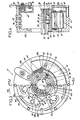
- FIGS. 1 and 2 A first embodiment of the torque limiter according to the invention is shown in FIGS. 1 and 2.
- This torque limiter (1) essentially consists of a housing (2), which is capable of being fixed by means of screws placed in holes (3) distributed regularly over its periphery, on a flange or the like of a shaft. motor (not shown in the drawing) rotating in the direction of the arrow (20), and a hub (4) arranged coaxially inside this housing (2).
- This hub (4) is mounted on the driven shaft (5) of the transmission, the connection in rotation of these two elements (4, 5) being provided by complementary grooves (4a, 5a) provided respectively inside the hub (4) and on the periphery of the shaft (5).
- the axial locking of the hub (4) and of the shaft (5) is ensured using a quick locking device of a type known per se formed by two axes (6) housed in radial holes (4b) of the hub, each of these axes (6) being able to be pushed back by an associated lock (7) in a peripheral groove (5b) formed on the shaft (5) so as to ensure the axial locking of the hub (4) with respect to to the tree (5).
- the unlocking of the assembly is ensured by pushing the locks (7) against the springs (8) to which they are subjected, until their recesses (7a) are opposite the associated holes (4b) so as to allow retraction of the axes (6) in the bores (4b) and the recesses (7a).
- Slides (9) (six slides in the example of the drawing) are mounted which can be moved radially inside the housing (2).
- Each slide (9) comprises a cylindrical part (10), slidably mounted in an associated radial bore (2a) formed in the wall of the housing (2), and an equally cylindrical part (11) extending perpendicular to the part (10 ) at one end thereof and in the axial direction.
- This part (11) of each slide (9) is capable of sliding by each of its ends (11a) in radial grooves (2b) formed on the internal faces of the housing (2) during the radial displacement of the cylindrical part (10 ) of the same slide.
- Springs (14) of Belleville washer type or the like are interposed between the housing (2) and the part (11) of each slide (9) and urge the latter radially inwards.
- a drive (15) integral with the hub (4) is associated with each slide (9).
- Each driver (15) is rotatably mounted at one of its ends (15a) on an axis (16) fixed inside the hub, each axis (16) extending parallel to the axis of the hub (4) and the housing (2).
- each of these coaches has a rounded shape in an arc complementary to the cylindrical part (11) of the associated slide (9), which is able to come into contact with this part ( 11) of the slide (9) to drive the hub (4) through the housing (2).
- each of the coaches (15) is shaped so that its axis of rotation (16) is departed laterally relative to the line of application of the radial force F exerted on it by the associated slide (9) under the effect of the springs (14).
- Each driver (15) is, moreover, provided with a return spring (18) tending to return it to its re-coupling position, that is to say to its position shown in FIG. 1, once he was ruled out.
- a stop is associated with each coach (15).
- Each stop is formed by an axis (19) similar to the axes (16) and mounted inside the housing, or by a latch (7). These stops are intended to stop the movement of the coach (15) upon its return under the effect of the return spring (18).
- each slide (9) is subjected, on the one hand, to a drive torque and, on the other hand, to a centripetal force F produced by the springs (14).
- This centripetal force F is directed radially and along a line of force passing through the center of the part (11) of the slide, as shown in FIG. 1.
- the line of action of this force is therefore offset laterally relative to the axis of rotation of the associated driver (15) and the result is on this driver a resisting torque in the opposite direction to the driving torque induced by the housing (2).
- the re-coupling is carried out automatically by stopping the rotation of the housing (2), which allows the coaches (15) to abut against the axes (7, 19) under the effect of their return springs (18 ) associated.
- this torque limiter device operates progressively and in particular allows certain overloads to be absorbed. not exceeding a predetermined value of the torque before uncoupling, thanks to the springs (14).
- This device is, moreover, fully automatic and does not require any manual resetting by the user since it suffices, in fact, to stop the housing so that the device is automatically reactivated.
- this device operates independently of the speed of rotation, since it does not use the action of centrifugal force, and that it presents practically no internal stress at rest, since the springs (14) are practically relaxed in this position.
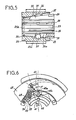
- the torque limiter (21) shown in Figures 3 to 8 operates on the same principle as the torque limiter (1) previously described.
- a housing made integral with the drive shaft of the driving part by means of screws placed in holes (23) of the housing and screwed into a flange or the like.
- this shaft and a hub (24) arranged coaxially inside this housing (22) and connected in translation and in rotation to the driven shaft of the transmission.
- connection between the hub (24) and the driven shaft of the transmission which is not shown in Figure 5 for clarity, but which is similar to the shaft (5) of Figures 1 to 2, is produced by means of an interchangeable assembly sleeve (25) and making it possible to link the hub (24) with any shaft profile (5).
- the sleeve (25) has a conical shape on the outside and internally has a cylindrical bore provided with grooves (25a) com p lementaries of grooves (5a) of the shaft (5).
- the grooves (25a) forming a hollow in the sleeve (25) are split, for example by sawing, over approximately three-quarters of their length, alternately from one end and the other of the sleeve (25) so as to form slots (28, 29) (six slots in the example of the drawing) extending alternately and respectively from the larger diameter end and the smaller diameter end of the sleeve.
- the sleeve (25) is provided externally at its end at the end of the smallest diameter with a peripheral groove (25b) capable of receiving a stop ring (26). It also has approximately in the middle three holes (25c), arranged radially and adapted to each receive a ball (27).
- the sleeve (25) is provided on its periphery, on the side of its larger diameter end with axial half-holes (30, 31) alternately smooth (30) and threaded (31), each half-hole being arranged at right of a cenneure (25a).
- the hub (24) has internally a conical bore (24a). It also has, like the sleeve (25), axial half-holes formed at its end at the end with the largest diameter, alternately threaded (32) and smooth (33), these half-holes opening into its inner wall. and having the same diameter as the half-holes (30, 31) of the sleeve and being able to cooperate with the respectively smooth (30) and threaded (31) half-holes of this sleeve (25) to receive screws not shown on the drawing.
- the lengths of the smooth half-holes respectively (30, 33) are shorter than those of the associated threaded half-holes respectively (32, 31) for a reason which will be explained later.
- Two circular grooves (35, 36) are formed in the conical bore of the hub (24) approximately in the middle of the latter.
- the groove (36) is located on the end side of the larger diameter hub and has a diameter greater than that of the groove (35).
- These two grooves (35, 36) are capable of receiving the balls (27) according to the position of the hub (24) relative to the sleeve (25) and are separated from each other by a ramp (37) facilitating the passage of these balls from one groove to another.
- the hub (24) can be adapted to any shaft profile (5); it suffices, in fact, for this to change the sleeve (25) by another sleeve whose internal profile is adapted to that of the shaft.
- the disassembly of the assembly is carried out very easily; it suffices, in fact, to remove the clamping screws from the holes (30, 32) in which they were housed, and to place them in the tapped half-holes (31) of the sleeve (25) and in the half-holes smooth (33) of the hub (24) and screw them.
- the housing (22) has substantially the shape of a cylindrical bowl (22a) closed by a cover (22b) and is driven by the drive shaft of the transmission in a clockwise direction.
- Each spring (39) is fixed by one end (39a) to the housing (22) by means of rivets (40) and its other end 39b is bent inwards.
- a trainer (45) is associated with each spring (39).
- Each driver (45) is, like the drivers (15) of the device described above, rotatably mounted on the hub (24).
- the hub (24) has a star shape and has six ridges (42) of triangular shape, distributed regularly around its periphery, and separated from each other by semi-circular recesses (43), each recess (43) being able to receive an end of complementary shape (45a) of a coach (45) and the faces (42a) of each crest (42) being able to serve as a stop for an associated coach (45) during of the retraction thereof.
- the coaches (45) are therefore housed by one end (45a) inside the recesses (43) of the hub (24) and are, moreover, connected together by this same end by means of two retaining washers (44) on which they are fixed by screws (50) and which are placed on either side of each driver (45) in the axial direction as shown in FIG. 4.
- One of the washers (44), that located on the side of the cover (22a) of the housing (22) is connected to a drive washer (47) extending externally to this washer (44) by a tension spring (49) .
- this spring (49) is fixed, by one end (49a), to a stud (48) integral with the washer (47), and by its other end in the form of an elongated loop (49b) , on the fixing screw (50) of one of the coaches (45) on the washer (44) located on the same side.
- the drive washer (47) is attached to the end (45b) of each driver by means of screws (51).
- Radial slots (53) are, moreover, provided on the washer (47) to allow the radial sliding of the fixing screws (51) of the coaches (45), during the pivoting of this drive washer (47).
- this tapped hole opens by a countersink (56) of larger diameter, in the abutment face (42a) of one of the ridges (42) and extends substantially perpendicular thereto.
- an additional security system (58).
- this system (58) is formed by a brake shoe (59) slidably mounted axially in the cover (22b) of the housing (2) and pressed axially against the drive washer (47) by a leaf spring (60) mounted on this same cover (22b).
- each flat spring (39) then exerts on the associated driver (45) a centripetal compression force F, directed substantially radially along a line of force ( 61) laterally offset (angle in FIG. 6) relative to the radius (62) passing through the center of rotation (45c) of this trainer.
- This force F therefore induces on the associated coach (45) a torque in the opposite direction to the driving torque CE and which therefore tends to make this coach pivot to the left in FIG. 6.
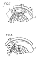
- the housing (22) pivots relative to the hub (24), the drives (45) moving slightly to the right, as shown in Figure 6 by the arrow (63) by rotation about their axis (45c), and, as in the previous example, the springs (39) retract by moving radially outward under the radial thrust of the coaches (45) caused by the displacement of these, and temporarily absorb the overload.
- the housing (22) continues to rotate independently of the hub (24) and the contact of the springs (39) with the drives (45) creates a clicking noise warning the user of the uncoupling.
- the springs (39) rotate the coaches (45) clockwise, until each of these comes to rest against an abutment face (42a) associated with the hub (24).
- the safety braking device (58) then immobilizes the drive washer (47) and the uncoupling coaches (45), by means of the brake shoe (59) pressed against this washer (47) by the spring (60 ), until the housing is stopped.
- the user To reset the device, the user must manually lift the brake shoe (59) by lifting the spring (60) in the direction of the arrow (65) to release the washer (47) which will then come back under the effect of the spring (49), as well as the coaches (45), in the reset position shown in dotted lines in FIG. 7 and it will then suffice to restart the casing (22) on to realize the flow again, this s 'performing automatically.
- This braking device (58) therefore provides additional security since it does not allow resetting of the torque limiter until the housing (22) has been stopped.
- the relative position of the driven and driving elements could be reversed, the hub then becoming the driving element and the housing the driven element.
- protrusions or recesses could be provided, in place of the slides or springs of the housing, to cooperate with the drives of the hub, without thereby departing from the scope of the present invention.
Landscapes
- Engineering & Computer Science (AREA)
- General Engineering & Computer Science (AREA)
- Mechanical Engineering (AREA)
- One-Way And Automatic Clutches, And Combinations Of Different Clutches (AREA)
- Arrangement And Driving Of Transmission Devices (AREA)
- Mechanical Operated Clutches (AREA)
- Transition And Organic Metals Composition Catalysts For Addition Polymerization (AREA)
Claims (12)
Priority Applications (1)
| Application Number | Priority Date | Filing Date | Title |
|---|---|---|---|
| AT85420141T ATE51687T1 (de) | 1984-07-26 | 1985-07-25 | Drehmomentbegrenzer. |
Applications Claiming Priority (2)
| Application Number | Priority Date | Filing Date | Title |
|---|---|---|---|
| FR8412105 | 1984-07-26 | ||
| FR8412105A FR2568331B1 (fr) | 1984-07-26 | 1984-07-26 | Limiteur de couple progressif a desaccouplement et reaccouplement automatique |
Publications (2)
| Publication Number | Publication Date |
|---|---|
| EP0170599A1 EP0170599A1 (de) | 1986-02-05 |
| EP0170599B1 true EP0170599B1 (de) | 1990-04-04 |
Family
ID=9306645
Family Applications (1)
| Application Number | Title | Priority Date | Filing Date |
|---|---|---|---|
| EP85420141A Expired - Lifetime EP0170599B1 (de) | 1984-07-26 | 1985-07-25 | Drehmomentbegrenzer |
Country Status (4)
| Country | Link |
|---|---|
| EP (1) | EP0170599B1 (de) |
| AT (1) | ATE51687T1 (de) |
| DE (1) | DE3576990D1 (de) |
| FR (1) | FR2568331B1 (de) |
Families Citing this family (2)
| Publication number | Priority date | Publication date | Assignee | Title |
|---|---|---|---|---|
| JP4025056B2 (ja) * | 2001-11-09 | 2007-12-19 | 小倉クラッチ株式会社 | 動力伝達機構 |
| CN115523244B (zh) * | 2021-06-25 | 2025-12-26 | 创领心律管理医疗器械(上海)有限公司 | 医疗设备的扭矩装置和医疗设备系统 |
Family Cites Families (11)
| Publication number | Priority date | Publication date | Assignee | Title |
|---|---|---|---|---|
| US1669225A (en) * | 1926-06-28 | 1928-05-08 | John K Bayles | Automatic release clutch |
| FR652278A (fr) * | 1928-04-05 | 1929-03-06 | Dispositif d'assemblage de deux arbres | |
| FR706290A (fr) * | 1930-02-21 | 1931-06-20 | Perfectionnements dans les accouplements | |
| FR39536E (fr) * | 1930-11-13 | 1931-11-30 | Dispositif permettant d'obtenir un embrayage, un changement de vitesse automatique, un renversement de marche et un frein | |
| US2551718A (en) * | 1946-05-10 | 1951-05-08 | Chrysler Corp | Stoker overload safety clutch |
| FR1131519A (fr) * | 1955-05-10 | 1957-02-22 | Dodge Mfg Corp | Dispositif de montage à coussinet pour poulies, roues dentées ou organes analogues |
| FR1198302A (fr) * | 1957-06-25 | 1959-12-07 | Dispositif d'accouplement | |
| GB881560A (en) * | 1959-06-26 | 1961-11-08 | Svenska Flaektfabriken Ab | Adjustable torque release coupling |
| US3303913A (en) * | 1964-12-28 | 1967-02-14 | Deere & Co | Torque-limiting clutch |
| US3682505A (en) * | 1969-10-31 | 1972-08-08 | David Firth | Means for mounting sheaves, etc. |
| GB1447483A (en) * | 1972-05-26 | 1976-08-25 | Gib Precision Ltd | Overload clutch |
-
1984
- 1984-07-26 FR FR8412105A patent/FR2568331B1/fr not_active Expired
-
1985
- 1985-07-25 DE DE8585420141T patent/DE3576990D1/de not_active Expired - Lifetime
- 1985-07-25 AT AT85420141T patent/ATE51687T1/de not_active IP Right Cessation
- 1985-07-25 EP EP85420141A patent/EP0170599B1/de not_active Expired - Lifetime
Also Published As
| Publication number | Publication date |
|---|---|
| ATE51687T1 (de) | 1990-04-15 |
| DE3576990D1 (de) | 1990-05-10 |
| FR2568331B1 (fr) | 1989-10-27 |
| EP0170599A1 (de) | 1986-02-05 |
| FR2568331A1 (fr) | 1986-01-31 |
Similar Documents
| Publication | Publication Date | Title |
|---|---|---|
| WO1998012444A1 (fr) | Embrayage a friction a dispositif de rattrapage d'usure, notamment pour vehicule automobile | |
| FR2725254A1 (fr) | Embrayage a friction, equipe d'un mecanisme limiteur de couples antagonistes a structure simplifiee | |
| EP2070725A1 (de) | Schnellspannsystem für Rad mit Kontrolle des Spannmoments | |
| EP1408522B1 (de) | Freilaufkupplungsanordnung für Federantrieb für Hochspannungsleistungsschalter | |
| FR2540583A1 (fr) | Systeme d'amortissement a disque | |
| FR2593871A1 (fr) | Volant amortisseur pour transmission, notamment pour vehicule automobile | |
| FR2600603A1 (fr) | Tendeur sur un enrouleur de ceinture de securite | |
| EP0917629A1 (de) | Reibungskupplung mit einer verschleiss-nachstelleinrichtung insbesondere für kraftfahrzeuge | |
| WO1999040335A1 (fr) | Mecanisme d'embrayage a friction, notamment pour vehicule automobile, comportant un dispositif de rattrapage d'usure | |
| EP0170599B1 (de) | Drehmomentbegrenzer | |
| FR2768206A1 (fr) | Ensemble de plateau de pression pour embrayage a friction a compensation d'usure | |
| EP0511067A1 (de) | Getriebe mit gesteuerter Flüssigkeitsreibungskupplung, insbesondere für Kraftfahrzeuge | |
| FR2650647A1 (fr) | Dispositif a vis sans fin | |
| EP1470882A1 (de) | Handwerkzeugmachine mit Sicherung | |
| EP0918000A1 (de) | Diebstahlsicherung für eine Kraftfahrzeuglenksäule | |
| FR2507720A1 (fr) | Disque de sortie d'embrayage a friction | |
| EP0288348B1 (de) | Antriebsvorrichtung eines drehbaren Organs, wie das Messer eines Rasenmähers | |
| FR2611378A1 (fr) | Ensemble de transmission a courroie pour vehicules a moteur, muni d'un dispositif de demarrage du moteur | |
| FR2564395A1 (fr) | Enrouleur de ceinture de securite | |
| FR2533649A1 (fr) | Dispositif amortisseur de torsion, en particulier friction d'embrayage, notamment pour vehicule automobile | |
| FR2526359A1 (fr) | Dispositif de freinage de securite pour chaine coupante de tronconneuse | |
| EP0077859B1 (de) | Schaltbare Reibungskupplung, insbesondere für Erntemaschinen | |
| FR2494028A1 (fr) | Mecanisme en charge avec debrayage en position terminale pour l'entrainement des commutateurs d'echelons pour transformateurs a echelons | |
| EP0298857A1 (de) | Hilfsanlaufeinrichtung, insbesondere ein Zweiradfahrzeug | |
| FR2798167A1 (fr) | Demarreur de vehicule automobile comportant un dispositif d'entrainement par friction |
Legal Events
| Date | Code | Title | Description |
|---|---|---|---|
| PUAI | Public reference made under article 153(3) epc to a published international application that has entered the european phase |
Free format text: ORIGINAL CODE: 0009012 |
|
| AK | Designated contracting states |
Designated state(s): AT BE CH DE FR GB IT LI LU NL SE |
|
| 17P | Request for examination filed |
Effective date: 19860730 |
|
| 17Q | First examination report despatched |
Effective date: 19871005 |
|
| GRAA | (expected) grant |
Free format text: ORIGINAL CODE: 0009210 |
|
| AK | Designated contracting states |
Kind code of ref document: B1 Designated state(s): AT BE CH DE FR GB IT LI LU NL SE |
|
| PG25 | Lapsed in a contracting state [announced via postgrant information from national office to epo] |
Ref country code: NL Effective date: 19900404 |
|
| REF | Corresponds to: |
Ref document number: 51687 Country of ref document: AT Date of ref document: 19900415 Kind code of ref document: T |
|
| REF | Corresponds to: |
Ref document number: 3576990 Country of ref document: DE Date of ref document: 19900510 |
|
| ITF | It: translation for a ep patent filed | ||
| GBT | Gb: translation of ep patent filed (gb section 77(6)(a)/1977) | ||
| NLV1 | Nl: lapsed or annulled due to failure to fulfill the requirements of art. 29p and 29m of the patents act | ||
| PLBE | No opposition filed within time limit |
Free format text: ORIGINAL CODE: 0009261 |
|
| STAA | Information on the status of an ep patent application or granted ep patent |
Free format text: STATUS: NO OPPOSITION FILED WITHIN TIME LIMIT |
|
| BERE | Be: lapsed |
Owner name: MAURE CHRISTIAN Effective date: 19900731 |
|
| 26N | No opposition filed | ||
| PGFP | Annual fee paid to national office [announced via postgrant information from national office to epo] |
Ref country code: GB Payment date: 19910725 Year of fee payment: 7 Ref country code: FR Payment date: 19910725 Year of fee payment: 7 |
|
| ITTA | It: last paid annual fee | ||
| PGFP | Annual fee paid to national office [announced via postgrant information from national office to epo] |
Ref country code: SE Payment date: 19910731 Year of fee payment: 7 Ref country code: AT Payment date: 19910731 Year of fee payment: 7 |
|
| PGFP | Annual fee paid to national office [announced via postgrant information from national office to epo] |
Ref country code: LU Payment date: 19910801 Year of fee payment: 7 Ref country code: DE Payment date: 19910801 Year of fee payment: 7 |
|
| PGFP | Annual fee paid to national office [announced via postgrant information from national office to epo] |
Ref country code: CH Payment date: 19910807 Year of fee payment: 7 |
|
| PGFP | Annual fee paid to national office [announced via postgrant information from national office to epo] |
Ref country code: BE Payment date: 19910809 Year of fee payment: 7 |
|
| EPTA | Lu: last paid annual fee | ||
| PG25 | Lapsed in a contracting state [announced via postgrant information from national office to epo] |
Ref country code: LU Free format text: LAPSE BECAUSE OF NON-PAYMENT OF DUE FEES Effective date: 19920725 Ref country code: GB Effective date: 19920725 Ref country code: AT Effective date: 19920725 |
|
| PG25 | Lapsed in a contracting state [announced via postgrant information from national office to epo] |
Ref country code: SE Effective date: 19920726 |
|
| PG25 | Lapsed in a contracting state [announced via postgrant information from national office to epo] |
Ref country code: LI Effective date: 19920731 Ref country code: CH Effective date: 19920731 Ref country code: BE Effective date: 19920731 |
|
| BERE | Be: lapsed |
Owner name: MAURE CHRISTIAN Effective date: 19920731 |
|
| GBPC | Gb: european patent ceased through non-payment of renewal fee |
Effective date: 19920725 |
|
| PG25 | Lapsed in a contracting state [announced via postgrant information from national office to epo] |
Ref country code: FR Effective date: 19930331 |
|
| REG | Reference to a national code |
Ref country code: CH Ref legal event code: PL |
|
| PG25 | Lapsed in a contracting state [announced via postgrant information from national office to epo] |
Ref country code: DE Effective date: 19930401 |
|
| REG | Reference to a national code |
Ref country code: FR Ref legal event code: ST |
|
| EUG | Se: european patent has lapsed |
Ref document number: 85420141.5 Effective date: 19930204 |