EP0511067A1 - Getriebe mit gesteuerter Flüssigkeitsreibungskupplung, insbesondere für Kraftfahrzeuge - Google Patents
Getriebe mit gesteuerter Flüssigkeitsreibungskupplung, insbesondere für Kraftfahrzeuge Download PDFInfo
- Publication number
- EP0511067A1 EP0511067A1 EP92401099A EP92401099A EP0511067A1 EP 0511067 A1 EP0511067 A1 EP 0511067A1 EP 92401099 A EP92401099 A EP 92401099A EP 92401099 A EP92401099 A EP 92401099A EP 0511067 A1 EP0511067 A1 EP 0511067A1
- Authority
- EP
- European Patent Office
- Prior art keywords
- coupling
- ramps
- counterweight
- members
- rotation
- Prior art date
- Legal status (The legal status is an assumption and is not a legal conclusion. Google has not performed a legal analysis and makes no representation as to the accuracy of the status listed.)
- Withdrawn
Links
Images


Classifications
-
- F—MECHANICAL ENGINEERING; LIGHTING; HEATING; WEAPONS; BLASTING
- F16—ENGINEERING ELEMENTS AND UNITS; GENERAL MEASURES FOR PRODUCING AND MAINTAINING EFFECTIVE FUNCTIONING OF MACHINES OR INSTALLATIONS; THERMAL INSULATION IN GENERAL
- F16D—COUPLINGS FOR TRANSMITTING ROTATION; CLUTCHES; BRAKES
- F16D35/00—Fluid clutches in which the clutching is predominantly obtained by fluid adhesion
- F16D35/005—Fluid clutches in which the clutching is predominantly obtained by fluid adhesion with multiple lamellae
Definitions
- the present invention relates to transmission devices, in particular for motor vehicles and more specifically such devices comprising a viscous fluid coupling generally designated by the terms viscocoupler or viscotransmitter.
- viscocouplers or viscotransmitters are of the type comprising an internal element and an external rotary element, coaxial, delimiting between them an enclosure containing a viscous fluid, each element being integral in rotation with a series of discs, the discs of the two series being alternated and at least partly embedded in the viscous fluid.
- One of the elements is driving and the other element is driven from the first under the effect of the resistive torque due to the shearing of the viscous fluid by the discs.
- the object of this invention is to propose a device which makes it possible to solve this problem and to vary more effectively and more favorably the operating characteristic of the viscous fluid coupling.
- the invention relates to a transmission device between two coaxial rotary members, comprising a viscous fluid coupling and control means for modifying the operating characteristic of this coupling, characterized in that said control means are integrated to the device and act as a function of the speed of rotation of one of said members and of a torque transmitted by the device.
- FIG. 1 a part of a motor vehicle differential comprising a housing 1, planet wheels 2 of which only one is visible in the drawing as well as satellites such as that designated by the reference 3, carried by a planet carrier axis 4.
- the sun gear 2 bears against a wall 5 of the housing and comprises at its rear part at least one ramp 6 cooperating with at least one complementary ramp 7 carried by a sleeve 8 connected by splines 9 to an output shaft 10 of axis XX.
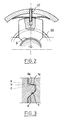
- a first set of ramps 6, 7 occurs when the coupling device has to transmit a motor torque, while the second set 6 a , 7 a is requested when the device transmits a braking torque.
- this second game of ramps may have with respect to the axial direction XX an inclination (c) in the same direction as that of the ramps 6, 7, a zero inclination (b) or an inclination (a) of opposite direction to that of the ramps 6, 7 .
- a viscous fluid coupling device 11 comprising an external housing 12 fixed on the differential housing and which delimits with the shaft 10 an enclosure 13 filled at least with part of a suitable viscous fluid such as silicone oil.
- the coupling device comprises two series of alternating discs 14, 15 respectively rotatably integral with the housing 12 and the shaft 10.
- an axially movable plate 16 is disposed in the housing 12 and in contact with the adjacent end of the sleeve 8 which extends with a sealed seal through a wall 17 of the housing 12.
- weights 21 movable radially and regularly angularly spaced are guided between the two opposite faces of the walls 5 and 17. These weights are also guided and made integral in rotation with the housing by guide pins 22 received in bores 23.
- Springs 24, for example leaf springs as shown in FIG. 2 stress the various weights radially inward.
- Each counterweight delimits, in its internal radial part, two ramps 25, 26 oriented in the same direction but at different angles.
- the first 25, directed towards the coupling device cooperates with a shuttle 27 received in an orifice 28 drilled in the wall 17. This shuttle when activated, has the effect of modifying the volume of the enclosure 13 and consequently the internal pressure in the latter.
- each counterweight directed towards the differential serves as a support for a disc 29 which itself serves as a stop for the sleeve 5.
- the contact surfaces 29 a between the sleeve and the disc are preferably frustoconical surfaces.
- a return spring 30, tending to separate the disc from the counterweight, is interposed between these two parts.
- the device according to the invention makes it possible to take into account both the speed of rotation of the differential housing and a torque transmitted by this differential, in order to modify the operating characteristic of the viscocoupler. These two parameters are taken into account in a determined order, that is to say first the speed then secondly the torque, which seems the most favorable in the application considered.
- the sleeve 8 comprises a radial flange 8 a , one flat face of which bears against part of the wall 5 while its other curved face bears against the counterweights 31.
- a return spring constituted by a Belleville washer 32 biases this sleeve towards the sun gear 2.
- Each counterweight is articulated around an axis 33 on the wall 5 of the differential housing instead of being slidably mounted. It is recalled by a pin spring 34.
- Each counterweight is in contact by a ramp 35 with at least one shuttle 27 and serves as a stop at 36 for the sleeve 8.
- this device is little different from that described with reference to FIG. 1. Indeed below a determined speed of rotation of the differential housing, the weights 31 are in the low position and the sleeve 8 is held in the position shown in the drawing. The torque transmitted by the sun gear 2 has no effect on the axial position of the sleeve which abuts against the flyweights.
- the movement of the weights 31 outwards also has the effect of releasing the sleeve 8 which can then, under the effect of the force resulting from the torque exerted on the ramps 6 and 7, move to the left and push the plate 16
- This displacement has the effect of modifying the spacing between the disks of the coupling and consequently of modifying the operating characteristic of the latter.
- the device according to the invention was used to control the operation of a differential.
- this device is used as a viscotransmitter, between two members 41, 42 such as two sections of a longitudinal drive shaft.
- the member 41 is fixed to a housing 43 which constitutes one of the two elements of a viscous fluid coupling device 44.
- This bolt bowl is completed by an end cover 45 and by two radial partitions 46 and 47.
- This housing is rotatably supported by bearings 48 and 49 a shaft 50, connected for example by a flange to the other section 42 of the transmission.
- the internal element of the coupling device is a hollow shaft 51 externally fluted at 52, which is mounted to rotate freely relative to the housing 43 and relative to the internal shaft 50.
- the wall 46 and the hollow shaft 51 are arranged two series of alternating discs 53, 54 respectively integral in rotation with the housing and the hollow shaft.
- the latter is made integral in rotation by grooves 55 with a sleeve 56 which is slidably mounted and which is connected by ramps 57, 58 to a ring 59 itself connected by grooves 60 to the shaft 50.
- the sleeve sliding 56 crosses the wall 46 of the housing with a watertight seal and bears against a plate 61 capable of moving axially to modify the spacing between the discs 53 and 54.
- the device is completed by an assembly as already described with reference to the preceding figures 1 and 2 and which comprises four weights 62 mounted to slide radially between the two walls 46 and 47 and guided relative to the housing by centering pins 63. These weights are biased radially inwards by leaf springs 64. They act on shuttles 65 slidably mounted in orifices in the wall 46, and serve as stops for a disc 66 on which an inclined part of the sleeve 56 comes to bear. This disc and therefore the sleeve are biased to the right when considering FIG. 4 by a return spring 67.
- the operation of the device is as follows:
- the housing 43 is rotated and drives the hollow shaft 51 via the viscous fluid coupling device 44.
- This shaft 51 itself drives the shaft 50 and the output member via the sleeve 56 and ring 59.
- the weights and the sleeve 56 retain the position shown in the drawing and do not modify the operating characteristic of the viscous fluid coupling. It is only from the moment when the housing 43 reaches a determined speed of rotation, that the weights 62 are urged radially outwards by the centrifugal force and act on the shuttles 65 to modify the operating characteristic of the 'coupling.
- the weights also release the sleeve 56 which, under the action of the torque exerted on the ramps 57 and 58, moves axially to push the plate 61 against the spring 30, and reduce the spacing of the discs. of the coupling device.
- the shaft 50 can also be used as an input member, the housing 43 then becoming an output member. In this second case it is the speed of the output member which determines the change in characteristic of the coupling device.
- the device has been adapted so that the operating characteristic of the viscous fluid coupling is first modified as a function of the torque, the variation as a function of the speed of one of the elements only intervening in a second step.
- each counterweight 71 comprises two ramps, a first ramp 72 situated in its external radial part and intended to cooperate with the shuttle 73 and a second ramp 74 disposed radially more inside, and which is in contact with the disc 75
- the disc is placed axially between the ramp 74 of the counterweight and the wall 47 delimiting the coupling device.
- the sleeve 76 is supported by a radial shoulder 77 against the disc 75, the latter being recalled to the right by considering the design by a Belleville washer 78.
- the weights 71 are locked in the internal radial position by the disc 75 which serves as a stop.
- the sleeve 76 is moved to the left, considering FIG. 5, which has the effect on the one hand of moving the plate 61 and on the other hand of moving the disc 75 to the left against the action of the spring 78.
- the weights are then released and can act on the shuttles 73 for also modifying the operating characteristic of the fluid coupling.
- ramps as shown in FIG. 3 may be provided in the various variants envisaged, while remaining within the scope of the invention.
- two devices as described with reference to FIGS. 4 and 5 can be combined to, for example, replace a conventional axle differential.
Landscapes
- Engineering & Computer Science (AREA)
- General Engineering & Computer Science (AREA)
- Mechanical Engineering (AREA)
- Arrangement And Driving Of Transmission Devices (AREA)
- Retarders (AREA)
Applications Claiming Priority (2)
| Application Number | Priority Date | Filing Date | Title |
|---|---|---|---|
| FR9105202A FR2675867A1 (fr) | 1991-04-26 | 1991-04-26 | Dispositif de transmission a viscocoupleur controle, notamment pour vehicule automobile. |
| FR9105202 | 1991-04-26 |
Publications (1)
| Publication Number | Publication Date |
|---|---|
| EP0511067A1 true EP0511067A1 (de) | 1992-10-28 |
Family
ID=9412310
Family Applications (1)
| Application Number | Title | Priority Date | Filing Date |
|---|---|---|---|
| EP92401099A Withdrawn EP0511067A1 (de) | 1991-04-26 | 1992-04-17 | Getriebe mit gesteuerter Flüssigkeitsreibungskupplung, insbesondere für Kraftfahrzeuge |
Country Status (4)
| Country | Link |
|---|---|
| US (1) | US5310382A (de) |
| EP (1) | EP0511067A1 (de) |
| JP (1) | JPH05126167A (de) |
| FR (1) | FR2675867A1 (de) |
Cited By (1)
| Publication number | Priority date | Publication date | Assignee | Title |
|---|---|---|---|---|
| EP0548853A1 (de) * | 1991-12-20 | 1993-06-30 | CENTRO RICERCHE FIAT Società Consortile per Azioni | System zur Kontrolle der Antriebsmomentverteilung zwischen den Rädern einer Achse |
Families Citing this family (9)
| Publication number | Priority date | Publication date | Assignee | Title |
|---|---|---|---|---|
| JP3373235B2 (ja) * | 1992-12-18 | 2003-02-04 | 栃木富士産業株式会社 | デファレンシャル装置 |
| GB9519200D0 (en) * | 1995-09-20 | 1995-11-22 | Vinten Group Plc | Improvements in or relating to rotary drag devices |
| DE19538351C1 (de) * | 1995-10-14 | 1997-05-07 | Walterscheid Gmbh Gkn | Kupplung zur Drehmomentbegrenzung |
| SE511836C2 (sv) * | 1996-04-29 | 1999-12-06 | Volvo Ab | Arrangemang och förfarande för kraftöverföring vid förbränningsmotor |
| DE19716488C2 (de) | 1997-04-19 | 2003-04-30 | Zf Sachs Ag | Torsionsschwingungsdämpfer mit einem Getriebe und einer Schaltvorrichtung hierfür |
| JPH10299834A (ja) * | 1997-04-23 | 1998-11-13 | Tochigi Fuji Ind Co Ltd | プロペラシャフト |
| US6554732B1 (en) | 2001-05-22 | 2003-04-29 | Spicer Technology, Inc. | Differential assembly with modified limited slip clutch arrangement |
| US6962546B1 (en) | 2002-08-09 | 2005-11-08 | Torque Traction Technologies, Inc. | Limited slip differential using fluid coupling |
| DE202011002608U1 (de) * | 2011-02-11 | 2012-02-29 | Camera Dynamics Gmbh | Stativkopf |
Citations (6)
| Publication number | Priority date | Publication date | Assignee | Title |
|---|---|---|---|---|
| US2684743A (en) * | 1947-03-31 | 1954-07-27 | Fairchild Engine & Airplane | Centrifugally operable clutch |
| US2714946A (en) * | 1948-12-08 | 1955-08-09 | Tenot Andre Louis | Hydraulic transmission |
| DE1288361B (de) * | 1960-10-20 | 1969-01-30 | Maybach Mercedes Benz Motorenb | Sicherheits-Reibkupplung fuer eine Lichtanlassmaschine |
| GB2135424A (en) * | 1983-02-15 | 1984-08-30 | Honda Motor Co Ltd | Torsional vibration absorbing device |
| DE3918822C1 (en) * | 1989-06-09 | 1990-03-29 | Viscodrive Gmbh, 5204 Lohmar, De | Liq. coupling - includes housing coupling section, hub, coupling parts etc. |
| EP0479639A1 (de) * | 1990-10-03 | 1992-04-08 | Glaenzer Spicer | Flüssigkeitsreibungskupplung mit variabler Charakteristik |
Family Cites Families (10)
| Publication number | Priority date | Publication date | Assignee | Title |
|---|---|---|---|---|
| US2387195A (en) * | 1941-04-30 | 1945-10-16 | Briggs Mfg Co | Coupling |
| NL7811860A (nl) * | 1978-12-05 | 1980-06-09 | Doornes Transmissie Bv | Hydraulisch bediende koppeling. |
| JPS57204348A (en) * | 1981-06-10 | 1982-12-15 | Honda Motor Co Ltd | Power transmission device equipped with flywheel with built-in viscous coupling |
| DE3447911A1 (de) * | 1983-12-03 | 1985-10-10 | Zahnradfabrik Friedrichshafen Ag, 7990 Friedrichshafen | Viskosekupplung, momentgesteuert |
| DE3408977A1 (de) * | 1984-03-12 | 1985-09-12 | Bayerische Motoren Werke AG, 8000 München | Fluessigkeitsreibungskupplung, insbesondere fuer ausgleichsgetriebe von kraftfahrzeugen |
| CA1257106A (en) * | 1985-02-25 | 1989-07-11 | Masao Teraoka | Power transmission apparatus |
| US4856637A (en) * | 1988-07-25 | 1989-08-15 | Horstman Manufacturing Co. | Centrifugal cone clutch |
| JP2536144B2 (ja) * | 1989-04-07 | 1996-09-18 | トヨタ自動車株式会社 | 動力伝達機構 |
| DE59003072D1 (de) * | 1989-08-21 | 1993-11-18 | Gkn Automotive Ag | Sperrbares Differentialgetriebe. |
| FR2663705A2 (fr) * | 1990-03-09 | 1991-12-27 | Glaenzer Spicer Sa | Amortisseur rotatif. |
-
1991
- 1991-04-26 FR FR9105202A patent/FR2675867A1/fr not_active Withdrawn
-
1992
- 1992-04-17 EP EP92401099A patent/EP0511067A1/de not_active Withdrawn
- 1992-04-23 US US07/872,448 patent/US5310382A/en not_active Expired - Fee Related
- 1992-04-27 JP JP4107733A patent/JPH05126167A/ja not_active Withdrawn
Patent Citations (6)
| Publication number | Priority date | Publication date | Assignee | Title |
|---|---|---|---|---|
| US2684743A (en) * | 1947-03-31 | 1954-07-27 | Fairchild Engine & Airplane | Centrifugally operable clutch |
| US2714946A (en) * | 1948-12-08 | 1955-08-09 | Tenot Andre Louis | Hydraulic transmission |
| DE1288361B (de) * | 1960-10-20 | 1969-01-30 | Maybach Mercedes Benz Motorenb | Sicherheits-Reibkupplung fuer eine Lichtanlassmaschine |
| GB2135424A (en) * | 1983-02-15 | 1984-08-30 | Honda Motor Co Ltd | Torsional vibration absorbing device |
| DE3918822C1 (en) * | 1989-06-09 | 1990-03-29 | Viscodrive Gmbh, 5204 Lohmar, De | Liq. coupling - includes housing coupling section, hub, coupling parts etc. |
| EP0479639A1 (de) * | 1990-10-03 | 1992-04-08 | Glaenzer Spicer | Flüssigkeitsreibungskupplung mit variabler Charakteristik |
Non-Patent Citations (1)
| Title |
|---|
| PATENT ABSTRACTS OF JAPAN vol. 7, no. 59 (M-199)(1204) 11 Mars 1983 & JP-A-57 204 348 ( HONDA ) 15 Décembre 1982 * |
Cited By (2)
| Publication number | Priority date | Publication date | Assignee | Title |
|---|---|---|---|---|
| EP0548853A1 (de) * | 1991-12-20 | 1993-06-30 | CENTRO RICERCHE FIAT Società Consortile per Azioni | System zur Kontrolle der Antriebsmomentverteilung zwischen den Rädern einer Achse |
| US5295921A (en) * | 1991-12-20 | 1994-03-22 | Centro Ricerche Fiat Societa Consortill Per Azioni | System for controlling torque distribution between the wheels of a common vehicle axle |
Also Published As
| Publication number | Publication date |
|---|---|
| JPH05126167A (ja) | 1993-05-21 |
| FR2675867A1 (fr) | 1992-10-30 |
| US5310382A (en) | 1994-05-10 |
Similar Documents
| Publication | Publication Date | Title |
|---|---|---|
| EP2501960B1 (de) | Sperrdifferenzial mit dynamischer schubvorrichtung | |
| FR2804382A1 (fr) | Dispositif de distribution de couple | |
| FR2672949A1 (fr) | Dispositif de transmission de mouvement de rotation. | |
| FR2646814A1 (fr) | Dispositif d'entrainement pour vehicule automobile | |
| FR2525717A1 (fr) | Differentiel autobloquant | |
| FR2621964A1 (fr) | Mecanisme de crabotage | |
| EP0511067A1 (de) | Getriebe mit gesteuerter Flüssigkeitsreibungskupplung, insbesondere für Kraftfahrzeuge | |
| FR2644534A1 (fr) | Coupleur hydraulique et a friction comportant une chambre supplementaire receptrice de fluide visqueux | |
| EP0957293B1 (de) | Elektromagnetische Betätigungseinrichtung mit Gewindespindelantrieb | |
| EP3757414A1 (de) | Vorrichtung zur drehmomentübertragung | |
| EP0456563A1 (de) | Übertragungseinrichtung mit Differential und kontrollierte Rutschkupplung | |
| EP0470879B1 (de) | Differentialübertragungseinrichtung und Kupplung, insbesondere für ein Kraftfahrzeug | |
| EP3959449B1 (de) | Getriebekasten und motor mit einem solchen getriebekasten | |
| EP0511068A1 (de) | Differentialgetriebe und Flüssigkeitsreibungskupplung, insbesondere für Kraftfahrzeuge | |
| EP0081025A1 (de) | Rotationsservomechanismus, insbesondere für eine Fahrzeuglenkung | |
| FR2706188A1 (fr) | Dispositif de transmission de rotation. | |
| FR2706190A1 (fr) | Dispositif de transmission de rotation. | |
| FR2706554A1 (fr) | Dispositif de transmission de rotation. | |
| FR2615918A1 (fr) | Systeme de commande automatique d'un embrayage d'accouplement de deux arbres rotatifs | |
| FR2624942A1 (fr) | Differentiel a reponse lineaire et glissement limite | |
| FR2551818A1 (fr) | Embrayage a friction et a disques multiples pour motocyclettes | |
| EP0356276B1 (de) | Differentialsystem mit veränderlichem gesteuertem Schlupf | |
| FR3092793A1 (fr) | Dispositif de transmission de couple pour un véhicule automobile | |
| BE376692Q (fr) | Perfectionnements aux mécanismes de transmission de force motrice à vitesse variable | |
| EP3857090B1 (de) | Kompakter doppelnasskupplungsmechanismus |
Legal Events
| Date | Code | Title | Description |
|---|---|---|---|
| PUAI | Public reference made under article 153(3) epc to a published international application that has entered the european phase |
Free format text: ORIGINAL CODE: 0009012 |
|
| AK | Designated contracting states |
Kind code of ref document: A1 Designated state(s): DE ES FR GB IT |
|
| 17P | Request for examination filed |
Effective date: 19920928 |
|
| STAA | Information on the status of an ep patent application or granted ep patent |
Free format text: STATUS: THE APPLICATION HAS BEEN WITHDRAWN |
|
| 18W | Application withdrawn |
Withdrawal date: 19930805 |