EP4385379B1 - Rotierender pad-halter für staubsauger - Google Patents
Rotierender pad-halter für staubsauger Download PDFInfo
- Publication number
- EP4385379B1 EP4385379B1 EP22213880.2A EP22213880A EP4385379B1 EP 4385379 B1 EP4385379 B1 EP 4385379B1 EP 22213880 A EP22213880 A EP 22213880A EP 4385379 B1 EP4385379 B1 EP 4385379B1
- Authority
- EP
- European Patent Office
- Prior art keywords
- pad holder
- openings
- water
- pad
- radius
- Prior art date
- Legal status (The legal status is an assumption and is not a legal conclusion. Google has not performed a legal analysis and makes no representation as to the accuracy of the status listed.)
- Active
Links
Images


Classifications
-
- A—HUMAN NECESSITIES
- A47—FURNITURE; DOMESTIC ARTICLES OR APPLIANCES; COFFEE MILLS; SPICE MILLS; SUCTION CLEANERS IN GENERAL
- A47L—DOMESTIC WASHING OR CLEANING; SUCTION CLEANERS IN GENERAL
- A47L9/00—Details or accessories of suction cleaners, e.g. mechanical means for controlling the suction or for effecting pulsating action; Storing devices specially adapted to suction cleaners or parts thereof; Carrying-vehicles specially adapted for suction cleaners
- A47L9/02—Nozzles
- A47L9/04—Nozzles with driven brushes or agitators
- A47L9/0461—Dust-loosening tools, e.g. agitators, brushes
- A47L9/0466—Rotating tools
- A47L9/0472—Discs
-
- A—HUMAN NECESSITIES
- A47—FURNITURE; DOMESTIC ARTICLES OR APPLIANCES; COFFEE MILLS; SPICE MILLS; SUCTION CLEANERS IN GENERAL
- A47L—DOMESTIC WASHING OR CLEANING; SUCTION CLEANERS IN GENERAL
- A47L11/00—Machines for cleaning floors, carpets, furniture, walls, or wall coverings
- A47L11/28—Floor-scrubbing machines, motor-driven
- A47L11/282—Floor-scrubbing machines, motor-driven having rotary tools
- A47L11/283—Floor-scrubbing machines, motor-driven having rotary tools the tools being disc brushes
-
- A—HUMAN NECESSITIES
- A47—FURNITURE; DOMESTIC ARTICLES OR APPLIANCES; COFFEE MILLS; SPICE MILLS; SUCTION CLEANERS IN GENERAL
- A47L—DOMESTIC WASHING OR CLEANING; SUCTION CLEANERS IN GENERAL
- A47L11/00—Machines for cleaning floors, carpets, furniture, walls, or wall coverings
- A47L11/40—Parts or details of machines not provided for in groups A47L11/02 - A47L11/38, or not restricted to one of these groups, e.g. handles, arrangements of switches, skirts, buffers, levers
- A47L11/4036—Parts or details of the surface treating tools
- A47L11/4038—Disk shaped surface treating tools
-
- A—HUMAN NECESSITIES
- A47—FURNITURE; DOMESTIC ARTICLES OR APPLIANCES; COFFEE MILLS; SPICE MILLS; SUCTION CLEANERS IN GENERAL
- A47L—DOMESTIC WASHING OR CLEANING; SUCTION CLEANERS IN GENERAL
- A47L11/00—Machines for cleaning floors, carpets, furniture, walls, or wall coverings
- A47L11/40—Parts or details of machines not provided for in groups A47L11/02 - A47L11/38, or not restricted to one of these groups, e.g. handles, arrangements of switches, skirts, buffers, levers
- A47L11/408—Means for supplying cleaning or surface treating agents
- A47L11/4088—Supply pumps; Spraying devices; Supply conduits
Definitions
- the present invention relates to a rotating pad holder adapted to hold a textile pad and adapted to be engaged with a driving unit of a wet vacuum cleaner nozzle having a water supply unit, wherein the pad holder comprises a first set of openings arranged in a circle, where the center of the circle coincides with a rotation axis of the pad holder and an arrangement of ribs for water distribution.
- Vacuum cleaners with mopping function are well known form the state of the art.
- Vacuum cleaners of different types e.g. canister vacuum cleaners, hand held vacuum cleaners, upright vacuum cleaners or autonomous vacuum cleaners are often designed to be able not only vacuuming the dirt but also wiping the surface to make the cleaning effect enhanced.
- Wet vacuum cleaners allows the user to reduce the time spared for cleaning the floor in comparison to the standard devices like vacuum cleaner and mopping device.
- the patent document WO 2021/ 020 908 A1 discloses mobile robot including a body, a mop module installed on the body and cleaning through using water, a water tank provided at the body to be able to be drawn out from the body and storing water supplied to the mop module, and a water-tank detachable module installed on the water tank.
- the water-tank detachable module includes a hook engaged with or coupled to the body and an operation button exposed at a surface of the water tank to operate the hook.
- the patent document EP 3 741 281 A1 discloses a cleaner capable of autonomously traveling while performing a mopping task, the cleaner including: a body which defines an exterior appearance of the cleaner; at least one mop module which has at least one mop provided in contact with a floor, and which supports the body against the floor; and a tilt information acquisition unit configured to acquire tilt information of the body in relation to the floor.
- At least one specific part may comprise the at least one mop, may be a whole or part of the at least one mop module, and may be defined such that the at least one specific part is provided detachable from other parts of the cleaner except for the at least one specific part and that the body tilts in relation to the floor due to gravity while the at least one specific part is separated from the other parts.
- the cleaner may further comprises a controller which is configured to: based on at least the tilt information, determine satisfaction or unsatisfaction of a predetermined separated condition that is preset to be satisfied when the specific part is separated from the other parts; and, when the detachments condition is satisfied, control a predetermined mop separation error response operation.
- a controller which is configured to: based on at least the tilt information, determine satisfaction or unsatisfaction of a predetermined separated condition that is preset to be satisfied when the specific part is separated from the other parts; and, when the detachments condition is satisfied, control a predetermined mop separation error response operation.
- the patent document WO 2021/ 233 055 A1 discloses a suction nozzle structure and a suction and mopping all-in-one machine, comprising a base assembly, the base assembly comprising a base support, and the base support comprising a suction nozzle mounting groove and a hinge channel mounting position; a dust collection component, the dust collection component comprising a base dust collection channel and a suction nozzle assembly; and floor mopping components mounted on the base support, each of the floor mopping components comprising a driving part and a cleaning part, and the floor mopping components being symmetrically provided on two sides of the base dust collection channel; wherein the base dust collection channel comprises a hinge channel and an insertion pipe, the hinge channel being located at the hinge channel mounting position; the suction nozzle assembly comprises a suction cavity; the suction cavity has a bottom end attached to a surface to be cleaned, and a top end of which the central part is a mounting groove; the shape of the suction nozzle assembly coincides with the suction nozzle mounting groove; when
- the patent document US 5 587 021 A discloses a method for the treatment of a surface, the surface being bare floor, a tiled floor or a floor with a covering including a carpet, upon an application of an auxiliary medium and an application of heat with a machine, wherein the machine has means for heating an air stream, at least one rotary disk and at least one drive dish with an opening through said dish for the passage of said hot air stream and at least one opening for said auxiliary medium, comprising the steps: heating said air stream to provide a heated air stream; pre-heating said auxiliary medium in said heated air stream to provide a pre-heated auxiliary medium; directing said heated air stream through said drive dish; directing said pre-heated auxiliary medium through said drive dish; heating said pre-heated auxiliary medium with said heated air stream as said pre-heated auxiliary medium and said heated air stream pass through said drive dish.
- An apparatus suitable for this purpose comprises a drive dish provided with clearances and comprises a hot air generator.
- the drive dish can be fashioned as a
- the object of the present invention is solved by a rotating pad holder for vacuum cleaner having a first set and a second set of openings wherein outer walls of the second set of openings are inclined towards the center of the pad holder.
- a pad holder is a disc shaped element which is adapted to hold a textile pad and adapted to be engaged with a driving unit of a wet vacuum cleaner nozzle.
- the driving unit rotates the pad holder with a textile pad and wipes the floor.
- the nozzle has a water supply unit.
- the water supply unit is a simple water outlet through which water is delivered from a water tank to the pad holder and then to the textile pad which wipes the cleaning surface.
- the pad holder has a first set of openings arranged in a circle wherein the center of the circle coincides with a rotation axis of the pad holder.
- the pad holder has also a second set of openings which are arranged on a circle which radius is greater than the radius of the circle on which the first set of openings is located.
- the first set of openings is located near the center of the pad holder and the second set of openings is an outer set in relation to the first set of openings.
- the water is fed by the water supply unit close to the rotation axis of the pad holder on the first set of openings.
- the pad holder has also an arrangement of ribs which helps the water distribution. Water is distributed by the ribs to the second set of openings.
- the outer walls of openings of the second set are inclined towards the center of the pad holder which limits the amount of water thrown out from the pad holder by the centrifugal force.
- the positive effect is that the water is distributed to the pad evenly which positively influences the cleaning effect.
- the water supply unit is placed above the first set of openings.
- the water supply unit is a simple outlet connected with a water tank of a vacuum cleaner through which the water is fed into the pad holder.
- the water supply unit is placed above the first set of openings which are located close to the axis of rotation of the pad holder. Thanks to the centrifugal force, the water is delivered by the arrangements of ribs to the cleaning surface.
- the ribs are grooved for water distribution.
- the ribs are responsible for delivering the water from first set of openings where the water is supplied by the water supply unit to the second set of openings which are an outer set located on exterior part of the pad holder.
- the water flows to the second set of openings through ribs which are grooved for better water channeling.
- the positive effect is that the water is distributed to the pad evenly which positively influences the quality of the cleaning process.
- each opening of the first set has a first supply zone.
- the first supply zone is an area under the water supply unit which position is constant.
- Each four openings of the second set has a second supply zone.
- the water from the second supply zone is delivered to each of four openings of the second set by grooved ribs.
- the size of the first supply zone differs from the size of the second supply zone as the water from the first supply zone feeds only one opening of the first set and the second supply zone is designed in such a way to feed four openings of the second set.
- the positive effect is that the water is distributed evenly which enhances the cleaning results.
- the ratio between the radial dimension of the second supply zone to the radial dimension of the first supply zone is the same as the ratio between the radius on which the first set of openings is located to the radius on which the second set of openings is located.
- the present invention enables a rotating pad holder for vacuum cleaner of construction which facilitates the evenness of water distribution and faster penetration of the water into the pad thanks to which the device is ready for operation very fast.
- the cleaning results of the device are improved with no production costs increase.
- Fig. 1 shows a pad holder 10 with a water supply unit 17 in isometric view.
- the pad holder 10 is a disc shaped element which is designed to hold a textile pad (not shown on the figure) in order to clean the floor.
- the water supply unit 17 is a simple nozzle which provides a water to the pad holder 10. The position of the water supply unit 17 is constant and water is delivered in the point of the pad holder 10 in vicinity of the rotation axis of the pad holder 10.
- Fig. 2 shows the pad holder 10 top view with a first set 11 and a second set 12 of openings 15.
- the first set 11 and the second set 12 of openings 15 were marked grey on the figure.
- the first set 11 of openings 15 is a set of six openings arranged on a circle in the vicinity of the rotation axis of the pad holder.
- the second set 12 of openings 15 is a set of twenty four openings arranged on a circle which radius R2 is greater than the radius R1 on which the first set 11 of openings 15 is arranged.
- the water supply unit 17 position is constant and water feeds all openings 15 thanks to the rotation of the pad holder 10.
- the water supply unit 17 is placed above the openings 15 of the first set 11 and thanks to the Coriolis force during rotation and the ribs 13 the water is delivered to the second set 12 of openings 15.
- Fig. 3 shows the pad holder 10 top view with openings 15 and ribs 13.
- Ribs 13 are grooved in order to facilitate the water to be spread on the surface of the pad holder 10 and further on the cleaning surface i.e. floor.
- Ribs 13 and openings 15 are arranged in a pattern which allows the water to be distributed to the cleaning surface evenly.
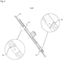
- Fig. 4 shows the cross section of the pad holder 10 shown on Fig. 3 .
- the outer walls 16 of the openings 15 of the second set 12 are inclined at angle ⁇ towards the center of the pad holder 10 which limits the amount of water thrown out from the centrifugal force occurring during rotation of the pad holder 10.
- the inclination additionally facilitates the penetration of water into the textile pad as a result of the emergence of an additional force.
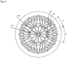
- Fig. 5 shows the pad holder 10 top view with a first supply zone 18 and a second supply zone 19.
- the first supply zone 18 is an area in which the water is delivered to the first set of openings 15.
- the first supply zone 18 feeds one opening 15 which is positioned on the circle of radius R1.
- the second supply zone 12 feeds four openings 15 which are positioned on the circle of radius R2.
- the water is distributed over the surface of the pad holder 10 and further to the textile pad in order to clean the surface.
- the present invention enables a rotating pad holder for vacuum cleaner of construction which facilitates the evenness of water distribution and faster penetration of the water into the pad thanks to which the device is ready for operation very fast.
- the cleaning results of the device are improved with no production costs increase.
Landscapes
- Engineering & Computer Science (AREA)
- Mechanical Engineering (AREA)
- Nozzles For Electric Vacuum Cleaners (AREA)
Claims (6)
- Rotierender Pad-Halter (10), der angepasst ist, um ein textiles Pad (20) zu halten, und angepasst ist, um mit einer Antriebseinheit einer Nass-Staubsaugerdüse, die eine Wasserversorgungseinheit (17) aufweist, in Eingriff gebracht zu werden, wobei der Pad-Halter (10) einen ersten Satz (11) von in einem Kreis angeordneten Öffnungen (15) umfasst, wobei sich die Mitte des Kreises mit einer Rotationsachse des Pad-Halters (10) und einer Anordnung von Rippen (13) zur Wasserverteilung deckt, wobei ein zweiter Satz (12) von Öffnungen (15) an einem Kreis angeordnet ist, dessen Radius (R2) größer als der Radius (R1) des Kreises ist, an dem sich der erste Satz (11) von Öffnungen (15) befindet, dadurch gekennzeichnet, dass Außenwände (16) von Öffnungen (15) des zweiten Satzes (12) in Richtung der Mitte des Pad-Halters (10) geneigt sind.
- Pad-Halter (10) nach Anspruch 1, dadurch gekennzeichnet, dass die Wasserversorgungseinheit (17) über dem ersten Satz (11) von Öffnungen (15) platziert ist.
- Pad-Halter (10) nach einem der vorhergehenden Ansprüche, dadurch gekennzeichnet, dass die Rippen (13) zur Wasserverteilung gerillt sind.
- Pad-Halter (10) nach einem der vorhergehenden Ansprüche, dadurch gekennzeichnet, dass jede Öffnung (15) des ersten Satzes (11) eine erste Versorgungszone (18) aufweist.
- Pad-Halter (10) nach einem der vorhergehenden Ansprüche, dadurch gekennzeichnet, dass jede der vier Öffnungen (15) des zweiten Satzes (12) eine zweite Versorgungszone (19) aufweist.
- Pad-Halter (10) nach einem der vorhergehenden Ansprüche 4-5, dadurch gekennzeichnet, dass das Verhältnis zwischen der radialen Abmessung (b) der zweiten Versorgungszone (19) zu der radialen Abmessung (a) der ersten Versorgungszone (18) das gleiche ist wie das Verhältnis zwischen dem Radius (R1), an dem sich der erste Satz (11) von Öffnungen (15) befindet, zu dem Radius (R2), an dem sich der zweite Satz (12) von Öffnungen (15) befindet.
Priority Applications (1)
| Application Number | Priority Date | Filing Date | Title |
|---|---|---|---|
| EP22213880.2A EP4385379B1 (de) | 2022-12-15 | 2022-12-15 | Rotierender pad-halter für staubsauger |
Applications Claiming Priority (1)
| Application Number | Priority Date | Filing Date | Title |
|---|---|---|---|
| EP22213880.2A EP4385379B1 (de) | 2022-12-15 | 2022-12-15 | Rotierender pad-halter für staubsauger |
Publications (2)
| Publication Number | Publication Date |
|---|---|
| EP4385379A1 EP4385379A1 (de) | 2024-06-19 |
| EP4385379B1 true EP4385379B1 (de) | 2025-05-21 |
Family
ID=84537247
Family Applications (1)
| Application Number | Title | Priority Date | Filing Date |
|---|---|---|---|
| EP22213880.2A Active EP4385379B1 (de) | 2022-12-15 | 2022-12-15 | Rotierender pad-halter für staubsauger |
Country Status (1)
| Country | Link |
|---|---|
| EP (1) | EP4385379B1 (de) |
Family Cites Families (5)
| Publication number | Priority date | Publication date | Assignee | Title |
|---|---|---|---|---|
| DE4233888A1 (de) * | 1992-10-10 | 1994-04-14 | Reinhard Dipl Ing Hoersch | Verfahren und Vorrichtung zur Reinigung und/oder Pflege von Bodenbelägen aller Art |
| US6514354B2 (en) * | 1993-09-08 | 2003-02-04 | Cyclone Surface Cleaning, Inc. | Surface cleaner and retrieval unit |
| KR102021827B1 (ko) | 2018-01-19 | 2019-09-17 | 엘지전자 주식회사 | 청소기 |
| KR102326334B1 (ko) | 2019-07-31 | 2021-11-12 | 엘지전자 주식회사 | 이동 로봇 |
| WO2021233055A1 (zh) | 2020-05-21 | 2021-11-25 | 安徽大汉机器人集团有限公司 | 一种吸嘴结构及吸拖一体机 |
-
2022
- 2022-12-15 EP EP22213880.2A patent/EP4385379B1/de active Active
Also Published As
| Publication number | Publication date |
|---|---|
| EP4385379A1 (de) | 2024-06-19 |
Similar Documents
| Publication | Publication Date | Title |
|---|---|---|
| US3686707A (en) | Foam extractor for rotary scrubber | |
| CN208677291U (zh) | 机动化地板拖把 | |
| US4692959A (en) | Rotary cleaner/scrubber mechanism | |
| USRE39623E1 (en) | Sprayless surface cleaner | |
| US5587021A (en) | Method and apparatus for the cleaning and/or care of floors and/or floor coverings of all types | |
| US4441229A (en) | Rotary cleaner-polisher | |
| CN104755003B (zh) | 用于清洁表面的清洁设备的喷嘴装置 | |
| CA2255728C (en) | Extractor with twin, counterrotating agitators | |
| US3789449A (en) | Hard surface floor cleaner | |
| US4881288A (en) | Center feed dispenser for cleaning solution | |
| CN102186393B (zh) | 用于湿式地面清洁的设备 | |
| US9295366B2 (en) | Rotary cleaning head having indirect fluid application | |
| CN115736723B (zh) | 滚刷组件、清洁头装置、清洁设备及方法 | |
| KR20050105229A (ko) | 추출 장치 및 오물 이송 소제 매체를 활용한 이중 모드카페트 소제 장치 | |
| CN104869881A (zh) | 用于清洁表面的清洁设备 | |
| CN115135214B (zh) | 用于清洁器具的清洁器头 | |
| CN103188980A (zh) | 适于抽吸式清洗机的罐托盘 | |
| US3212117A (en) | Foam generating floor conditioner | |
| WO1994006343A1 (en) | Applicator head for surface cleaning appliances | |
| US5517715A (en) | Cleaning head | |
| CN217365722U (zh) | 一种用于清洁机器人的基站 | |
| EP4385379A1 (de) | Rotierender pad-halter für staubsauger | |
| CN115530686B (zh) | 清洁机系统 | |
| USRE24583E (en) | Automatic floor mop | |
| JPH05331759A (ja) | タイルカーペット洗浄機 |
Legal Events
| Date | Code | Title | Description |
|---|---|---|---|
| PUAI | Public reference made under article 153(3) epc to a published international application that has entered the european phase |
Free format text: ORIGINAL CODE: 0009012 |
|
| STAA | Information on the status of an ep patent application or granted ep patent |
Free format text: STATUS: THE APPLICATION HAS BEEN PUBLISHED |
|
| AK | Designated contracting states |
Kind code of ref document: A1 Designated state(s): AL AT BE BG CH CY CZ DE DK EE ES FI FR GB GR HR HU IE IS IT LI LT LU LV MC ME MK MT NL NO PL PT RO RS SE SI SK SM TR |
|
| STAA | Information on the status of an ep patent application or granted ep patent |
Free format text: STATUS: REQUEST FOR EXAMINATION WAS MADE |
|
| GRAP | Despatch of communication of intention to grant a patent |
Free format text: ORIGINAL CODE: EPIDOSNIGR1 |
|
| STAA | Information on the status of an ep patent application or granted ep patent |
Free format text: STATUS: GRANT OF PATENT IS INTENDED |
|
| 17P | Request for examination filed |
Effective date: 20241219 |
|
| INTG | Intention to grant announced |
Effective date: 20250128 |
|
| GRAS | Grant fee paid |
Free format text: ORIGINAL CODE: EPIDOSNIGR3 |
|
| GRAA | (expected) grant |
Free format text: ORIGINAL CODE: 0009210 |
|
| STAA | Information on the status of an ep patent application or granted ep patent |
Free format text: STATUS: THE PATENT HAS BEEN GRANTED |
|
| AK | Designated contracting states |
Kind code of ref document: B1 Designated state(s): AL AT BE BG CH CY CZ DE DK EE ES FI FR GB GR HR HU IE IS IT LI LT LU LV MC ME MK MT NL NO PL PT RO RS SE SI SK SM TR |
|
| REG | Reference to a national code |
Ref country code: GB Ref legal event code: FG4D |
|
| REG | Reference to a national code |
Ref country code: CH Ref legal event code: EP |
|
| REG | Reference to a national code |
Ref country code: DE Ref legal event code: R096 Ref document number: 602022014926 Country of ref document: DE |
|
| REG | Reference to a national code |
Ref country code: IE Ref legal event code: FG4D |
|
| REG | Reference to a national code |
Ref country code: NL Ref legal event code: MP Effective date: 20250521 |
|
| PG25 | Lapsed in a contracting state [announced via postgrant information from national office to epo] |
Ref country code: PT Free format text: LAPSE BECAUSE OF FAILURE TO SUBMIT A TRANSLATION OF THE DESCRIPTION OR TO PAY THE FEE WITHIN THE PRESCRIBED TIME-LIMIT Effective date: 20250922 Ref country code: FI Free format text: LAPSE BECAUSE OF FAILURE TO SUBMIT A TRANSLATION OF THE DESCRIPTION OR TO PAY THE FEE WITHIN THE PRESCRIBED TIME-LIMIT Effective date: 20250521 Ref country code: ES Free format text: LAPSE BECAUSE OF FAILURE TO SUBMIT A TRANSLATION OF THE DESCRIPTION OR TO PAY THE FEE WITHIN THE PRESCRIBED TIME-LIMIT Effective date: 20250521 |
|
| REG | Reference to a national code |
Ref country code: LT Ref legal event code: MG9D |
|
| PG25 | Lapsed in a contracting state [announced via postgrant information from national office to epo] |
Ref country code: NO Free format text: LAPSE BECAUSE OF FAILURE TO SUBMIT A TRANSLATION OF THE DESCRIPTION OR TO PAY THE FEE WITHIN THE PRESCRIBED TIME-LIMIT Effective date: 20250821 Ref country code: GR Free format text: LAPSE BECAUSE OF FAILURE TO SUBMIT A TRANSLATION OF THE DESCRIPTION OR TO PAY THE FEE WITHIN THE PRESCRIBED TIME-LIMIT Effective date: 20250822 |
|
| PG25 | Lapsed in a contracting state [announced via postgrant information from national office to epo] |
Ref country code: NL Free format text: LAPSE BECAUSE OF FAILURE TO SUBMIT A TRANSLATION OF THE DESCRIPTION OR TO PAY THE FEE WITHIN THE PRESCRIBED TIME-LIMIT Effective date: 20250521 Ref country code: PL Free format text: LAPSE BECAUSE OF FAILURE TO SUBMIT A TRANSLATION OF THE DESCRIPTION OR TO PAY THE FEE WITHIN THE PRESCRIBED TIME-LIMIT Effective date: 20250521 |
|
| PG25 | Lapsed in a contracting state [announced via postgrant information from national office to epo] |
Ref country code: BG Free format text: LAPSE BECAUSE OF FAILURE TO SUBMIT A TRANSLATION OF THE DESCRIPTION OR TO PAY THE FEE WITHIN THE PRESCRIBED TIME-LIMIT Effective date: 20250521 |
|
| PG25 | Lapsed in a contracting state [announced via postgrant information from national office to epo] |
Ref country code: HR Free format text: LAPSE BECAUSE OF FAILURE TO SUBMIT A TRANSLATION OF THE DESCRIPTION OR TO PAY THE FEE WITHIN THE PRESCRIBED TIME-LIMIT Effective date: 20250521 |
|
| PG25 | Lapsed in a contracting state [announced via postgrant information from national office to epo] |
Ref country code: RS Free format text: LAPSE BECAUSE OF FAILURE TO SUBMIT A TRANSLATION OF THE DESCRIPTION OR TO PAY THE FEE WITHIN THE PRESCRIBED TIME-LIMIT Effective date: 20250821 |
|
| PG25 | Lapsed in a contracting state [announced via postgrant information from national office to epo] |
Ref country code: IS Free format text: LAPSE BECAUSE OF FAILURE TO SUBMIT A TRANSLATION OF THE DESCRIPTION OR TO PAY THE FEE WITHIN THE PRESCRIBED TIME-LIMIT Effective date: 20250921 |
|
| PG25 | Lapsed in a contracting state [announced via postgrant information from national office to epo] |
Ref country code: LV Free format text: LAPSE BECAUSE OF FAILURE TO SUBMIT A TRANSLATION OF THE DESCRIPTION OR TO PAY THE FEE WITHIN THE PRESCRIBED TIME-LIMIT Effective date: 20250521 |
|
| REG | Reference to a national code |
Ref country code: AT Ref legal event code: MK05 Ref document number: 1796040 Country of ref document: AT Kind code of ref document: T Effective date: 20250521 |
|
| PG25 | Lapsed in a contracting state [announced via postgrant information from national office to epo] |
Ref country code: DK Free format text: LAPSE BECAUSE OF FAILURE TO SUBMIT A TRANSLATION OF THE DESCRIPTION OR TO PAY THE FEE WITHIN THE PRESCRIBED TIME-LIMIT Effective date: 20250521 Ref country code: AT Free format text: LAPSE BECAUSE OF FAILURE TO SUBMIT A TRANSLATION OF THE DESCRIPTION OR TO PAY THE FEE WITHIN THE PRESCRIBED TIME-LIMIT Effective date: 20250521 Ref country code: SM Free format text: LAPSE BECAUSE OF FAILURE TO SUBMIT A TRANSLATION OF THE DESCRIPTION OR TO PAY THE FEE WITHIN THE PRESCRIBED TIME-LIMIT Effective date: 20250521 |
|
| PGFP | Annual fee paid to national office [announced via postgrant information from national office to epo] |
Ref country code: FR Payment date: 20251218 Year of fee payment: 4 |
|
| PGFP | Annual fee paid to national office [announced via postgrant information from national office to epo] |
Ref country code: TR Payment date: 20251209 Year of fee payment: 4 |
|
| PG25 | Lapsed in a contracting state [announced via postgrant information from national office to epo] |
Ref country code: CZ Free format text: LAPSE BECAUSE OF FAILURE TO SUBMIT A TRANSLATION OF THE DESCRIPTION OR TO PAY THE FEE WITHIN THE PRESCRIBED TIME-LIMIT Effective date: 20250521 |
|
| PG25 | Lapsed in a contracting state [announced via postgrant information from national office to epo] |
Ref country code: EE Free format text: LAPSE BECAUSE OF FAILURE TO SUBMIT A TRANSLATION OF THE DESCRIPTION OR TO PAY THE FEE WITHIN THE PRESCRIBED TIME-LIMIT Effective date: 20250521 |
|
| PG25 | Lapsed in a contracting state [announced via postgrant information from national office to epo] |
Ref country code: SK Free format text: LAPSE BECAUSE OF FAILURE TO SUBMIT A TRANSLATION OF THE DESCRIPTION OR TO PAY THE FEE WITHIN THE PRESCRIBED TIME-LIMIT Effective date: 20250521 |
|
| PG25 | Lapsed in a contracting state [announced via postgrant information from national office to epo] |
Ref country code: IT Free format text: LAPSE BECAUSE OF FAILURE TO SUBMIT A TRANSLATION OF THE DESCRIPTION OR TO PAY THE FEE WITHIN THE PRESCRIBED TIME-LIMIT Effective date: 20250521 |
|
| REG | Reference to a national code |
Ref country code: DE Ref legal event code: R097 Ref document number: 602022014926 Country of ref document: DE |
|
| PG25 | Lapsed in a contracting state [announced via postgrant information from national office to epo] |
Ref country code: RO Free format text: LAPSE BECAUSE OF FAILURE TO SUBMIT A TRANSLATION OF THE DESCRIPTION OR TO PAY THE FEE WITHIN THE PRESCRIBED TIME-LIMIT Effective date: 20250521 |
|
| PLBE | No opposition filed within time limit |
Free format text: ORIGINAL CODE: 0009261 |
|
| STAA | Information on the status of an ep patent application or granted ep patent |
Free format text: STATUS: NO OPPOSITION FILED WITHIN TIME LIMIT |
|
| REG | Reference to a national code |
Ref country code: CH Ref legal event code: L10 Free format text: ST27 STATUS EVENT CODE: U-0-0-L10-L00 (AS PROVIDED BY THE NATIONAL OFFICE) Effective date: 20260402 |
|
| PGFP | Annual fee paid to national office [announced via postgrant information from national office to epo] |
Ref country code: DE Payment date: 20251231 Year of fee payment: 4 |
|
| 26N | No opposition filed |
Effective date: 20260224 |