EP4382433B1 - Luftfahrzeug mit mindestens einer wasserstoffversorgungsvorrichtung mit einem wasserstoffspeicher sowie in mindestens einem speicherfesten behälter und mindestens einem abnehmbaren behälter verteilt angeordneten einrichtungen - Google Patents
Luftfahrzeug mit mindestens einer wasserstoffversorgungsvorrichtung mit einem wasserstoffspeicher sowie in mindestens einem speicherfesten behälter und mindestens einem abnehmbaren behälter verteilt angeordneten einrichtungen Download PDFInfo
- Publication number
- EP4382433B1 EP4382433B1 EP23209277.5A EP23209277A EP4382433B1 EP 4382433 B1 EP4382433 B1 EP 4382433B1 EP 23209277 A EP23209277 A EP 23209277A EP 4382433 B1 EP4382433 B1 EP 4382433B1
- Authority
- EP
- European Patent Office
- Prior art keywords
- container
- upstream
- downstream
- containers
- aircraft
- Prior art date
- Legal status (The legal status is an assumption and is not a legal conclusion. Google has not performed a legal analysis and makes no representation as to the accuracy of the status listed.)
- Active
Links
Images


Classifications
-
- B—PERFORMING OPERATIONS; TRANSPORTING
- B64—AIRCRAFT; AVIATION; COSMONAUTICS
- B64D—EQUIPMENT FOR FITTING IN OR TO AIRCRAFT; FLIGHT SUITS; PARACHUTES; ARRANGEMENT OR MOUNTING OF POWER PLANTS OR PROPULSION TRANSMISSIONS IN AIRCRAFT
- B64D37/00—Arrangements in connection with fuel supply for power plant
- B64D37/02—Tanks
- B64D37/14—Filling or emptying
- B64D37/20—Emptying systems
-
- B—PERFORMING OPERATIONS; TRANSPORTING
- B64—AIRCRAFT; AVIATION; COSMONAUTICS
- B64D—EQUIPMENT FOR FITTING IN OR TO AIRCRAFT; FLIGHT SUITS; PARACHUTES; ARRANGEMENT OR MOUNTING OF POWER PLANTS OR PROPULSION TRANSMISSIONS IN AIRCRAFT
- B64D37/00—Arrangements in connection with fuel supply for power plant
- B64D37/30—Fuel systems for specific fuels
-
- B—PERFORMING OPERATIONS; TRANSPORTING
- B64—AIRCRAFT; AVIATION; COSMONAUTICS
- B64D—EQUIPMENT FOR FITTING IN OR TO AIRCRAFT; FLIGHT SUITS; PARACHUTES; ARRANGEMENT OR MOUNTING OF POWER PLANTS OR PROPULSION TRANSMISSIONS IN AIRCRAFT
- B64D37/00—Arrangements in connection with fuel supply for power plant
- B64D37/32—Safety measures not otherwise provided for, e.g. preventing explosive conditions
-
- F—MECHANICAL ENGINEERING; LIGHTING; HEATING; WEAPONS; BLASTING
- F17—STORING OR DISTRIBUTING GASES OR LIQUIDS
- F17C—VESSELS FOR CONTAINING OR STORING COMPRESSED, LIQUEFIED OR SOLIDIFIED GASES; FIXED-CAPACITY GAS-HOLDERS; FILLING VESSELS WITH, OR DISCHARGING FROM VESSELS, COMPRESSED, LIQUEFIED, OR SOLIDIFIED GASES
- F17C1/00—Pressure vessels, e.g. gas cylinder, gas tank, replaceable cartridge
-
- F—MECHANICAL ENGINEERING; LIGHTING; HEATING; WEAPONS; BLASTING
- F17—STORING OR DISTRIBUTING GASES OR LIQUIDS
- F17C—VESSELS FOR CONTAINING OR STORING COMPRESSED, LIQUEFIED OR SOLIDIFIED GASES; FIXED-CAPACITY GAS-HOLDERS; FILLING VESSELS WITH, OR DISCHARGING FROM VESSELS, COMPRESSED, LIQUEFIED, OR SOLIDIFIED GASES
- F17C2201/00—Vessel construction, in particular geometry, arrangement or size
- F17C2201/01—Shape
- F17C2201/0104—Shape cylindrical
- F17C2201/0109—Shape cylindrical with exteriorly curved end-piece
-
- F—MECHANICAL ENGINEERING; LIGHTING; HEATING; WEAPONS; BLASTING
- F17—STORING OR DISTRIBUTING GASES OR LIQUIDS
- F17C—VESSELS FOR CONTAINING OR STORING COMPRESSED, LIQUEFIED OR SOLIDIFIED GASES; FIXED-CAPACITY GAS-HOLDERS; FILLING VESSELS WITH, OR DISCHARGING FROM VESSELS, COMPRESSED, LIQUEFIED, OR SOLIDIFIED GASES
- F17C2205/00—Vessel construction, in particular mounting arrangements, attachments or identifications means
- F17C2205/01—Mounting arrangements
- F17C2205/0123—Mounting arrangements characterised by number of vessels
- F17C2205/013—Two or more vessels
- F17C2205/0134—Two or more vessels characterised by the presence of fluid connection between vessels
-
- F—MECHANICAL ENGINEERING; LIGHTING; HEATING; WEAPONS; BLASTING
- F17—STORING OR DISTRIBUTING GASES OR LIQUIDS
- F17C—VESSELS FOR CONTAINING OR STORING COMPRESSED, LIQUEFIED OR SOLIDIFIED GASES; FIXED-CAPACITY GAS-HOLDERS; FILLING VESSELS WITH, OR DISCHARGING FROM VESSELS, COMPRESSED, LIQUEFIED, OR SOLIDIFIED GASES
- F17C2205/00—Vessel construction, in particular mounting arrangements, attachments or identifications means
- F17C2205/03—Fluid connections, filters, valves, closure means or other attachments
- F17C2205/0302—Fittings, valves, filters, or components in connection with the gas storage device
- F17C2205/0323—Valves
- F17C2205/0326—Valves electrically actuated
-
- F—MECHANICAL ENGINEERING; LIGHTING; HEATING; WEAPONS; BLASTING
- F17—STORING OR DISTRIBUTING GASES OR LIQUIDS
- F17C—VESSELS FOR CONTAINING OR STORING COMPRESSED, LIQUEFIED OR SOLIDIFIED GASES; FIXED-CAPACITY GAS-HOLDERS; FILLING VESSELS WITH, OR DISCHARGING FROM VESSELS, COMPRESSED, LIQUEFIED, OR SOLIDIFIED GASES
- F17C2221/00—Handled fluid, in particular type of fluid
- F17C2221/01—Pure fluids
- F17C2221/012—Hydrogen
-
- F—MECHANICAL ENGINEERING; LIGHTING; HEATING; WEAPONS; BLASTING
- F17—STORING OR DISTRIBUTING GASES OR LIQUIDS
- F17C—VESSELS FOR CONTAINING OR STORING COMPRESSED, LIQUEFIED OR SOLIDIFIED GASES; FIXED-CAPACITY GAS-HOLDERS; FILLING VESSELS WITH, OR DISCHARGING FROM VESSELS, COMPRESSED, LIQUEFIED, OR SOLIDIFIED GASES
- F17C2223/00—Handled fluid before transfer, i.e. state of fluid when stored in the vessel or before transfer from the vessel
- F17C2223/01—Handled fluid before transfer, i.e. state of fluid when stored in the vessel or before transfer from the vessel characterised by the phase
- F17C2223/0146—Two-phase
- F17C2223/0153—Liquefied gas, e.g. LPG, GPL
- F17C2223/0161—Liquefied gas, e.g. LPG, GPL cryogenic, e.g. LNG, GNL, PLNG
-
- F—MECHANICAL ENGINEERING; LIGHTING; HEATING; WEAPONS; BLASTING
- F17—STORING OR DISTRIBUTING GASES OR LIQUIDS
- F17C—VESSELS FOR CONTAINING OR STORING COMPRESSED, LIQUEFIED OR SOLIDIFIED GASES; FIXED-CAPACITY GAS-HOLDERS; FILLING VESSELS WITH, OR DISCHARGING FROM VESSELS, COMPRESSED, LIQUEFIED, OR SOLIDIFIED GASES
- F17C2223/00—Handled fluid before transfer, i.e. state of fluid when stored in the vessel or before transfer from the vessel
- F17C2223/03—Handled fluid before transfer, i.e. state of fluid when stored in the vessel or before transfer from the vessel characterised by the pressure level
- F17C2223/033—Small pressure, e.g. for liquefied gas
-
- F—MECHANICAL ENGINEERING; LIGHTING; HEATING; WEAPONS; BLASTING
- F17—STORING OR DISTRIBUTING GASES OR LIQUIDS
- F17C—VESSELS FOR CONTAINING OR STORING COMPRESSED, LIQUEFIED OR SOLIDIFIED GASES; FIXED-CAPACITY GAS-HOLDERS; FILLING VESSELS WITH, OR DISCHARGING FROM VESSELS, COMPRESSED, LIQUEFIED, OR SOLIDIFIED GASES
- F17C2227/00—Transfer of fluids, i.e. method or means for transferring the fluid; Heat exchange with the fluid
- F17C2227/01—Propulsion of the fluid
- F17C2227/0128—Propulsion of the fluid with pumps or compressors
- F17C2227/0135—Pumps
-
- F—MECHANICAL ENGINEERING; LIGHTING; HEATING; WEAPONS; BLASTING
- F17—STORING OR DISTRIBUTING GASES OR LIQUIDS
- F17C—VESSELS FOR CONTAINING OR STORING COMPRESSED, LIQUEFIED OR SOLIDIFIED GASES; FIXED-CAPACITY GAS-HOLDERS; FILLING VESSELS WITH, OR DISCHARGING FROM VESSELS, COMPRESSED, LIQUEFIED, OR SOLIDIFIED GASES
- F17C2227/00—Transfer of fluids, i.e. method or means for transferring the fluid; Heat exchange with the fluid
- F17C2227/03—Heat exchange with the fluid
-
- F—MECHANICAL ENGINEERING; LIGHTING; HEATING; WEAPONS; BLASTING
- F17—STORING OR DISTRIBUTING GASES OR LIQUIDS
- F17C—VESSELS FOR CONTAINING OR STORING COMPRESSED, LIQUEFIED OR SOLIDIFIED GASES; FIXED-CAPACITY GAS-HOLDERS; FILLING VESSELS WITH, OR DISCHARGING FROM VESSELS, COMPRESSED, LIQUEFIED, OR SOLIDIFIED GASES
- F17C2265/00—Effects achieved by gas storage or gas handling
- F17C2265/06—Fluid distribution
- F17C2265/066—Fluid distribution for feeding engines for propulsion
-
- F—MECHANICAL ENGINEERING; LIGHTING; HEATING; WEAPONS; BLASTING
- F17—STORING OR DISTRIBUTING GASES OR LIQUIDS
- F17C—VESSELS FOR CONTAINING OR STORING COMPRESSED, LIQUEFIED OR SOLIDIFIED GASES; FIXED-CAPACITY GAS-HOLDERS; FILLING VESSELS WITH, OR DISCHARGING FROM VESSELS, COMPRESSED, LIQUEFIED, OR SOLIDIFIED GASES
- F17C2270/00—Applications
- F17C2270/01—Applications for fluid transport or storage
- F17C2270/0102—Applications for fluid transport or storage on or in the water
- F17C2270/0105—Ships
-
- F—MECHANICAL ENGINEERING; LIGHTING; HEATING; WEAPONS; BLASTING
- F17—STORING OR DISTRIBUTING GASES OR LIQUIDS
- F17C—VESSELS FOR CONTAINING OR STORING COMPRESSED, LIQUEFIED OR SOLIDIFIED GASES; FIXED-CAPACITY GAS-HOLDERS; FILLING VESSELS WITH, OR DISCHARGING FROM VESSELS, COMPRESSED, LIQUEFIED, OR SOLIDIFIED GASES
- F17C2270/00—Applications
- F17C2270/01—Applications for fluid transport or storage
- F17C2270/0186—Applications for fluid transport or storage in the air or in space
-
- Y—GENERAL TAGGING OF NEW TECHNOLOGICAL DEVELOPMENTS; GENERAL TAGGING OF CROSS-SECTIONAL TECHNOLOGIES SPANNING OVER SEVERAL SECTIONS OF THE IPC; TECHNICAL SUBJECTS COVERED BY FORMER USPC CROSS-REFERENCE ART COLLECTIONS [XRACs] AND DIGESTS
- Y02—TECHNOLOGIES OR APPLICATIONS FOR MITIGATION OR ADAPTATION AGAINST CLIMATE CHANGE
- Y02E—REDUCTION OF GREENHOUSE GAS [GHG] EMISSIONS, RELATED TO ENERGY GENERATION, TRANSMISSION OR DISTRIBUTION
- Y02E60/00—Enabling technologies; Technologies with a potential or indirect contribution to GHG emissions mitigation
- Y02E60/30—Hydrogen technology
- Y02E60/32—Hydrogen storage
Definitions
- the present application relates to an aircraft comprising at least one hydrogen supply device comprising a hydrogen tank assembled to the aircraft as well as equipment distributed in at least one container connected to the tank and at least one removable container.
- a hydrogen supply device for an aircraft comprises at least one hydrogen tank 10 as well as several hydrogen circuits 12.1 to 12.4 each having at least one upstream end 14.1 to 14.2 connected to the hydrogen tank 10 and at least one downstream end 16.1 to 16.4 connected in particular to at least one hydrogen engine or to at least one fuel cell.
- the concepts upstream and downstream refer to the direction of flow of hydrogen in each of the hydrogen circuits, which flows from upstream to downstream.
- Each hydrogen circuit 12.1 to 12.4 comprises conduits 18 as well as various equipment 20, such as pumps, sensors, valves or exchangers for example, connected to each other by the conduits 18.
- the hydrogen supply device may comprise at least one electrical cable 22 connected to at least one piece of equipment 20.
- the hydrogen is stored in the hydrogen tank 10 in a cryogenic state and the hydrogen supply device includes a high pressure pump for pressurizing the hydrogen and a heat exchanger configured to heat the hydrogen from the liquid state to the gaseous state.
- the conduits 18 are double-skinned pipes to prevent any hydrogen leakage.
- Some equipment 20, such as certain valves for example, are configured to ensure a high level of safety in terms of hydrogen leakage.
- Other equipment 20, such as pumps for example it proves complex to obtain a high level of safety in terms of hydrogen leakage or this leads to high costs for this equipment.
- the equipment 20, the conduits 18 as well as the electric cables 22 are positioned in an airtight container 24 into which an inert gas is injected or a vacuum is created.
- This container 24 is connected in a sealed manner to the hydrogen tank 10.
- the document US2015/0298811 provides an energy unit that includes a first cart supporting a storage unit and a second cart supporting a fuel cell unit, the storage and fuel cell units being coupleable.
- the document EP4037046 proposes a fuel cell grouping device comprising at least two fuel cells, a support on which the different fuel cells are positioned, a feeder configured to supply the fuel cells and a collector configured to collect a fluid leaving the fuel cells, the support comprising a casing, the collector and the feeder being integral with the casing and positioned between the casing and the fuel cells.
- the present invention aims to remedy all or part of the drawbacks of the prior art.
- the invention relates to an aircraft comprising at least one hydrogen supply device comprising at least one hydrogen tank assembled to the aircraft, at least one hydrogen circuit and at least one upstream container secured to the hydrogen tank.
- the hydrogen supply device comprises at least one removable downstream container, the upstream and downstream containers being configured to occupy an assembled state in which the upstream and downstream containers are connected and a detached state in which the upstream and downstream containers are separated, the hydrogen circuit comprising an upstream section positioned in the upstream container, a downstream section positioned in the downstream container as well as a first connection system connecting the upstream and downstream sections when the upstream and downstream containers are in the assembled state.
- the upstream and downstream containers respectively comprise upstream and downstream joining faces positioned at a joining zone and close to each other in the assembled state, the first connection system being positioned close to the joining zone when the upstream and downstream containers are in the assembled state.
- the hydrogen supply device comprises at least one removable intermediate container interposed between the upstream and downstream containers, the upstream and intermediate containers being configured to occupy an assembled state in which the upstream and intermediate containers are brought together in a first junction zone and a detached state in which the upstream and intermediate containers are separated, the downstream and intermediate containers being configured to occupy an assembled state in which the downstream and intermediate containers are brought together in a second junction zone and a detached state in which the downstream and intermediate containers are separated.
- the hydrogen circuit comprises an intermediate section interposed between the upstream and downstream sections and positioned in the intermediate container, a first connection system, connecting the upstream and intermediate sections, positioned at the first junction zone and a second connection system, connecting the downstream and intermediate sections, positioned at the second junction zone.
- the hydrogen supply device comprises at least one electric cable comprising a section for each container among upstream, downstream and intermediate containers in which the electric cable is present as well as a connector connecting the different sections two by two.
- each of the upstream and downstream containers is gas-tight and contains a protective atmosphere.
- each connection system comprises a first part secured to a first section from among an upstream section, a downstream section and if present an intermediate section, positioned in a first container from among an upstream container, a downstream container and if present an intermediate container as well as a second part secured to a second section from among an upstream section, a downstream section and if present an intermediate section, positioned in a second container from among an upstream container, a downstream container and if present an intermediate container; the first and second parts being configured to occupy a connected state in which the first and second parts cooperate and ensure fluid continuity between the first and second sections as well as a disconnected state in which the first and second parts are separated.
- the first and second containers comprise first and second walls close to each other when the first and second containers are in an assembled state.
- first part of each connection system is positioned at the first wall and connected in a sealed manner to the latter.
- second part of each connection system is positioned at the second wall and connected in a sealed manner to the latter.
- the first part of each connection system is positioned outside the first container, the first section connected to the first part passing through the first wall in a sealed manner.
- the second part of each connection system is positioned inside the second container, the second wall of the second container comprising at least one through-orifice configured to allow the first part of each connection system to penetrate into the second container.
- the first part of each connection system is positioned outside the first container, the first section connected to the first part passing through the first wall in a sealed manner.
- the second part of each connection system is positioned inside the second container, the second wall of the second container comprising at least one through-orifice configured to allow the first container to be positioned in the second container.
- the hydrogen supply device comprises a plate connected to the first container and configured to seal the through-orifice in a gas-tight manner when the first container is positioned in the second container.
- the second container comprises at least one opening positioned so as to be able to access the connection systems from an exterior area of the second container as well as a hatch configured to occupy a closed state in which the hatch tightly closes the opening and an open state in which the hatch clears the opening.
- the first container comprises a partition dividing the first container into a first compartment located between the partition and the first wall and a second compartment distant from the first wall, the first part of each connection system being positioned in the first compartment, the first section connected to the first part passing through the partition in a sealed manner.
- the first wall comprises at least one through-hole to allow the second part of each connection system of the second container to penetrate into the first compartment.
- the first container comprises at least a first opening positioned so as to be able to access the connection systems from an exterior area of the first container as well as a first hatch configured to occupy a closed state in which the first hatch seals the first opening and an open state in which the first hatch clears the first opening.
- the hydrogen supply device comprises, for each first container, a housing secured to the second container and in which the second part of each connection system is positioned, the housing being configured to house a part of the first container.
- the housing comprises at least one second opening positioned in line with the first opening when the first and second containers are in the assembled state as well as a second hatch configured to occupy a closed state in which the second hatch sealably closes the second opening and an open state in which the second hatch clears the second opening.
- the hydrogen supply device comprises at least one seal inserted between, on the one hand, the first container and, on the other hand, the second container and/or the housing.
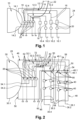
- a hydrogen supply device 28 comprises at least one hydrogen tank 30 as well as at least one hydrogen circuit 32.1 to 32.4 having at least one upstream end 34.1 to 34.2 connected to the hydrogen tank 30 and at least one downstream end 36.1 to 36.4 connected for example to at least one hydrogen engine or to at least one fuel cell.
- the hydrogen tank 30 comprises a cylindrical side wall 30.1 as well as end walls positioned at each end of the cylindrical side wall 30.1.
- the hydrogen tank 30 is not described further because it may be identical to those of the prior art.
- a hydrogen circuit 32.1 to 32.4 may comprise one or more upstream end(s) 34.1, 34.2. Several hydrogen circuits 32.1 to 32.4 may have the same upstream end 34.1, 34.2. Similarly, a hydrogen circuit 32.1 to 32.4 may comprise one or more downstream end(s) 36.1 to 36.4. Several hydrogen circuits 32.1 to 32.4 may have the same downstream end.
- the hydrogen supply device 28 comprises four hydrogen circuits 32.1 to 32.4 which each have a downstream end 36.1 to 36.4, the first and second hydrogen circuits 32.1, 32.1 having the same upstream end 34.1, the third and fourth hydrogen circuits 32.3, 32.4 having the same upstream end 34.2.
- the hydrogen supply device 28 comprises first and second equipments 38, 40 as well as conduits 42 connecting the first and second equipments 38, 40 and making it possible, for each hydrogen circuit 32.1 to 32.4, to convey the hydrogen from the upstream end 34.1, 34.2 to the downstream end 36.1 to 36.4 by passing through the first and second equipments 38, 40.
- the first and second pieces of equipment 38, 40 are chosen from a list of equipment including in particular valves, sensors, pumps, heat exchangers, evaporators, connection systems or others. This list is not exhaustive.
- the first pieces of equipment 38 like certain valves for example, belong to a first category of equipment and are configured to ensure a high level of safety in terms of hydrogen leakage.
- each first piece of equipment 38 comprises at least one sealed housing as well as at least one component, in contact with the fluid in operation, positioned in the sealed housing.
- the second equipment 40 such as certain pumps for example, belongs to a second category of equipment and is not configured to ensure a high level of safety in terms of hydrogen leakage.
- each hydrogen circuit 32.1 to 32.4 comprises at least one first equipment 38 as well as at least one second equipment 40.
- the hydrogen circuits may be distinct, have at least one common section and/or be connected by connecting conduits.
- the hydrogen supply device 28 comprises at least one upstream container 46 secured to the hydrogen tank 30, at least one removable downstream container 48, the upstream and downstream containers 46, 48 respectively comprising upstream and downstream joining faces 46.1, 48.1 at a joining zone 50, the upstream and downstream containers 46, 48 being configured to occupy an assembled state in which the downstream joining face 48.1 of the downstream container 48 and the upstream joining face 46.1 of the upstream container 46 are brought together (or even in contact with each other), as well as a detached state in which the downstream joining face 48.1 of the downstream container 48 and the upstream joining face 46.1 of the upstream container 46 are separated.
- Each of the upstream and downstream containers 46, 48 comprises at least one wall delimiting an inner zone and an outer zone.
- Each of the upstream and downstream containers 46, 48 is gas-tight and contains a protective atmosphere at least when the upstream and downstream containers 46, 48 are in the assembled state.
- the protective atmosphere may be a high vacuum level or an inert gas for example.
- the hydrogen supply device 28 comprises at least one first detachable connection 52 making it possible to maintain the downstream container 48 in the assembled state.
- the hydrogen supply device 28 may comprise at least one seal 54 inserted between the upstream and downstream containers 46, 48, more particularly between the upstream and downstream junction faces 46.1, 48.1.
- the upstream container 46 is pressed against the cylindrical side wall 30.1 of the hydrogen tank 30. According to another arrangement, the upstream container 46 is positioned in the extension of the hydrogen tank 30 and pressed against an end wall of said hydrogen tank.
- the hydrogen supply device 28 comprises a single upstream container 46 and two downstream containers 48.
- the invention is not limited to this configuration concerning the number of upstream and downstream containers 46, 48.
- each downstream container 48 has a substantially parallelepiped shape and a face which corresponds to the downstream junction face 48.1.
- the invention is not limited to this geometry for the downstream containers 48.
- the upstream container 46 comprises a body 56, substantially parallelepiped, attached to the hydrogen tank 30 and connected to the latter in a gas-tight manner as well as an extension 58 communicating with the body 56 and forming with the latter a recess 60 configured to house the downstream containers 48.
- the face of the extension 58 oriented towards the recess 60 forms the upstream junction face 46.1 of the upstream container 46.
- the invention is not limited to this geometry for the upstream container 46.
- the upstream and downstream containers 46, 48 are configured to obtain a compact assembly.
- At least one of the hydrogen circuits 32.1 to 32.4 comprises an upstream section 62 positioned in an upstream container 46, a downstream section 64 positioned in a downstream container 48 as well as a first connection system 66, connecting the upstream and downstream sections 62, 64, positioned at the junction zone 50 of the upstream and downstream containers 46, 48 when the latter are in the assembled state.
- all the hydrogen circuits 32.1 to 32.4 of the hydrogen supply device 28 each comprise an upstream section 62 positioned in an upstream container 46, a downstream section 64 positioned in a downstream container 48 as well as a first connection system 66 connecting the upstream and downstream sections 62, 64 and positioned at the level of the junction zone 50 of the upstream and downstream containers 46, 48 when the latter are in the assembled state.
- the upstream sections 62 of all the hydrogen circuits 32.1 to 32.4 are positioned in the same upstream container 46.
- the downstream sections 64 of the first and second hydrogen circuits 32.1, 32.2 are positioned in a first downstream container 48 and the downstream sections 64 of the third and fourth hydrogen circuits 32.3, 32.4 are positioned in a second downstream container 48.
- each upstream section 62 does not include any equipment 40 of the second category of equipment.
- Each upstream section 62 includes at least one equipment 38 of the first category of equipment.
- each downstream section 64 includes at least one equipment 40 of the second category of equipment.
- each downstream section 64 may include at least one equipment 38 of the first category of equipment.
- the hydrogen supply device 28 comprises at least one removable intermediate container 68 interposed between the upstream and downstream containers 46, 48.
- the upstream and intermediate containers 46, 68 respectively comprise an upstream junction face 46.1 and a first intermediate junction face 68.1 positioned at a first junction zone 50.
- the downstream and intermediate containers 48, 68 respectively comprise a downstream junction face 48.1 and a second intermediate junction face 68.2 positioned at a second junction zone 50'.
- the upstream and intermediate containers 46, 68 are configured to occupy an assembled state in which the upstream and intermediate containers 46, 68 (and more particularly the first intermediate joining face 68.1 of the intermediate container 68 and the upstream joining face 46.1 of the upstream container 46) are brought together (or even in contact with each other) in the first joining zone 50 as well as a detached state in which the upstream and intermediate containers 46, 68 (and more particularly the first intermediate joining face 68.1 of the intermediate container 68 and the upstream joining face 46.1 of the upstream container 46) are separated.
- the downstream and intermediate containers 48, 68 are configured to occupy an assembled state in which the downstream and intermediate containers 48, 68 (and more particularly the downstream joining face 48.1 of the downstream container 48 and the second intermediate joining face 68.2 of the intermediate container 68) are brought together (or even in contact with each other) in the second junction zone 50' as well as a detached state in which the downstream and intermediate containers 48, 68 (and more particularly the downstream junction face 48.1 of the downstream container 48 and the second intermediate junction face 68.2 of the intermediate container 68) are separated.
- each intermediate container 68 comprises at least one wall delimiting an interior zone and an exterior zone.
- each intermediate container 68 is gas-tight and contains a protective atmosphere at least when the upstream, intermediate and downstream containers 46, 68, 48 are in the assembled state.
- This protective atmosphere may be a high vacuum level or an inert gas for example.
- the hydrogen supply device 28 comprises at least one first detachable connection 52 making it possible to connect the downstream and intermediate containers 48, 68 and to keep them in the assembled state.
- the hydrogen supply device 28 comprises at least one second detachable connection making it possible to connect the upstream and intermediate containers 46, 68 and to keep them in the assembled state.
- the hydrogen supply device 28 comprises at least one first seal 54 inserted between the downstream and intermediate containers 48, 68, more particularly between the downstream junction face 48.1 and the second intermediate junction face 68.2.
- the hydrogen supply device 28 may comprise at least one second seal inserted between the upstream and intermediate containers 46, 68, more particularly between the upstream junction face 46.1 and the first intermediate junction face 68.1.
- the upstream container 46 is substantially parallelepipedal and has a face which corresponds to the upstream junction face 46.1.
- the intermediate container 68 has a substantially peripheral shape. It is positioned against upstream and downstream containers 46, 48 and comprises a face comprising a first part which forms the first intermediate junction face 68.1 (facing the upstream junction face 46.1) and a second part which forms the second intermediate junction face 68.2 (facing the downstream junction face 48.1).
- At least one of the hydrogen circuits 32.1 to 32.4 comprises an upstream section 62 positioned in an upstream container 46, a downstream section 64 positioned in a downstream container 48, an intermediate section 70 interposed between the upstream and downstream sections 62, 64 and positioned in an intermediate container 68, a first connection system 66, connecting the upstream and intermediate sections 62, 70, positioned at a first junction zone 50 (when the upstream and intermediate containers 46, 68 are in the assembled state) as well as a second connection system 66', connecting the downstream and intermediate sections 64, 70, positioned at a second junction zone 50' (when the downstream and intermediate containers 48, 68 are in the assembled state).
- all the hydrogen circuits 32.1 to 32.4 of the hydrogen supply device 28 each comprise an upstream section 62 positioned in an upstream container 46, a downstream section 64 positioned in a downstream container 48, an intermediate section 70 interposed between the upstream and downstream sections 62, 64 and positioned in an intermediate container 68, a first connection system 66, connecting the upstream and intermediate sections 62, 70, positioned at a first junction zone 50 (when the upstream and intermediate containers 46, 68 are in the assembled state) as well as a second connection system 66', connecting the downstream and intermediate sections 64, 70, positioned at a second junction zone 50' (when the downstream and intermediate containers 48, 68 are in the assembled state).
- each intermediate section 70 only comprises conduits 42.
- Each intermediate section 70 does not comprise any equipment 40 from the second category of equipment.
- the hydrogen supply device 28 comprises at least one upstream container 46 secured to the hydrogen tank 30 as well as at least one removable downstream container 48, the upstream and downstream containers 46, 48 being configured to occupy an assembled state in which the upstream and downstream containers 46, 48 are connected (directly or via an intermediate container 68), and a detached state in which the upstream and downstream containers 46, 48 are disconnected.
- the hydrogen supply device 28 comprises at least one electric cable 72 comprising at least one section 72.1, 72.2.
- Each of these electric cables 72 has a first end connected to a first or second piece of equipment 38, 40 as well as a second end connected to an element (not shown) located outside the upstream, downstream and intermediate containers 46, 48, 68.
- each electric cable 72 passes in a sealed manner through the wall of one of the upstream containers, downstream and intermediate 46, 48, 68.
- an electric cable 72 comprises several sections 72.1, 72.2, one section for each container among the upstream, downstream and intermediate containers 46, 48, 68 in which the electric cable 72 is present as well as a connector 74 connecting the sections two by two, one connector 74 for each junction zone 50, 50' crossed.
- each connection system 66, 66' comprises a first part 76.1 secured to a first section T1 among an upstream section 62, a downstream section 64 and an intermediate section 70 as well as a second part 76.2 secured to a second section T2 among an upstream section 62, a downstream section 64 and an intermediate section 70; the first and second parts 76.1, 76.2 being configured to occupy a connected state in which they cooperate and ensure fluid continuity between the first and second sections T1, T2 as well as a disconnected state in which they are separated.
- Each junction zone 50, 50' comprises a first wall 78.1 belonging to a first container C1 among the upstream, downstream and intermediate containers 46, 48, 68 and having a face which corresponds to one of the faces among the upstream junction face 46.1, the downstream junction face 48.1, the first and second intermediate junction faces 68.1, 68.2 as well as a second wall 78.1 belonging to a second container C2 among the upstream, downstream and intermediate containers 46, 48, 68 and having a face which corresponds to one of the faces among the upstream junction face 46.1, the downstream junction face 48.1, the first and second intermediate junction faces 68.1, 68.2.
- the first and second walls 78.1, 78.2 are brought together (or even in contact with each other) when the first and second containers C1, C2 are in the assembled state.
- each connection system 66, 66' is positioned at the first wall 78.1 and connected in a sealed manner to the latter.
- the second part 76.2 of each connection system 66, 66' is positioned at the second wall 78.2 and connected in a sealed manner to the latter.
- each connector 74 comprises a first part 74.1 positioned at the first wall 78.1 and connected in a sealed manner to the latter and a second part 74.2 positioned at the second wall 78.2 and connected in a sealed manner to the latter, the first and second parts 74.1, 74.2 being configured to occupy a first connected state in which they cooperate and ensure electrical continuity as well as a disconnected state in which they are separated.
- the first and second parts 76.1, 76.2 of each connection system 66, 66' as well as the first and second parts 74.1, 74.2 of each connector 74 are arranged so that, when the containers 46, 48, 68 associated with the first and second walls 78.1, 78.2 are in the assembled state, the first and second parts 76.1, 76.2, 74.1, 74.2 of each connection system 66, 66' and of each connector 74 are in the connected state.
- connection system 66, 66' of at least one junction zone 50, 50' its first part 76.1 is positioned outside the first container C1 and the first section T1 connected to this first part 76.1 passes through the first wall 78.1 in a sealed manner.
- first part 74.1 is positioned outside the first container C1, the cable connected to this first part 74.1 passing through the first wall 78.1 in a sealed manner.
- connection system 66, 66' its second part 76.2 is positioned inside the second container C2.
- second part 74.2 is also positioned inside the second container C2.
- the second wall 78.2 of the second container C2 comprises at least one through-orifice 80 (a through-orifice 80 dedicated to each connection system 66, 66' and each connector 74 or a single through-orifice 80 for all the connection systems 66, 66' and the connectors 74) configured to allow the first part of each connection system 66, 66' and each connector 74 to penetrate into the second container C2.
- the hydrogen supply device 28 may comprise a seal 54 interposed between the first and second walls 78.1, 78.2, around the through-orifice 80 in question.
- the second container C2 comprises at least one opening 82 positioned so as to be able to access the connection systems 66, 66' and the connectors 74 from the exterior zone of the second container C2 as well as a hatch 84 configured to occupy a closed state in which it seals the opening 82 and an open state in which it clears the opening 82.
- the first container C1 is positioned relative to the second container so that the first parts 76.1, 74.1 of the connection systems 66, 66' and of the connectors 74 are positioned facing the single through-orifice 80 or each facing the through-orifice 80 dedicated to it, as illustrated in part (A) of the Figure 4 .
- first and second containers C1, C2 are assembled, then the first and second parts 76.1, 74.1, 76.2, 74.2 of the connection systems 66, 66' and of the connector(s) 74 are connected, as illustrated in part (B) of the Figure 4 .
- the hatch 84 With the hatch 84 in the open state, it is possible to access the first and second parts 76.1, 74.1, 76.2, 74.2 to connect them.
- the hatch 84 is closed and a protective atmosphere can be put in place in the second container C2 by creating an appropriate vacuum or by injecting an inert gas.
- the first container C1 corresponds to the upstream or downstream container 46, 48 and the second container C2 corresponds to the intermediate container 68.
- the upstream and downstream containers 46, 48 are perfectly sealed and each contain a protective atmosphere.
- the intermediate container 68 only contains double-walled conduits and connection systems 66, 66' of the first category of equipment (ensuring a high level of safety in terms of hydrogen leakage), it does not need to be perfectly sealed and contain a protective atmosphere.
- connection system 66, 66' for each connection system 66, 66', its first part 76.1 is positioned outside the first container C1 and the first section T1 connected to this first part 76.1 passes in a sealed manner through the first wall 78.1 of the first container C1.
- first part 74.1 is positioned outside the first container C1, the cable connected to this first part 74.1 passing through the first wall 78.1 in a sealed manner.
- connection system 66, 66' its second part 76.2 is positioned inside the second container C2.
- second part 74.2 is positioned inside the second container C2.
- the second wall 78.2 of the second container C2 comprises a through-hole 80 sized to allow the first container C1 to pass through the through-hole 80 in order to be positioned in the second container C2.
- the hydrogen supply device 28 comprises at least one structure 86 to which the first container C1 is connected as well as a plate 88 secured to the structure 86 and configured to close the through-orifice 80 in a gas-tight manner when the first container C1 is positioned in the second container C2.
- the hydrogen supply device does not comprise a structure 86 but only a plate 88 connected or not to the first container C1 and configured to close the through-orifice 80 in a gas-tight manner, in particular when the first container C1 is positioned in the second container C2.
- the second container C2 comprises at least one opening 82 positioned so as to be able to access the connection systems 66, 66' and the connectors 74 from the exterior zone of the second container C2 as well as a hatch 84 configured to occupy a closed state in which it seals the opening 82 and an open state in which it clears the opening 82.
- a seal 90 may be inserted between the plate 88 and the second wall 78.2 of the second container C2, around the through-orifice 80, to reinforce the seal.
- the first container C1 corresponds to the downstream container 48 and the second container C2 corresponds to the intermediate container 68.
- the upstream container 46 and the intermediate container 68 are connected in the same way as for the embodiment visible on the Figures 3 and 4 .
- the first container C1 comprises a partition 92 substantially parallel to the first wall 78.1, dividing the first container C1 into a first compartment 94.1 located between the partition 92 and the first wall 78.1 as well as a second compartment 94.2 distant from the first wall 78.1. All the equipment 38, 40 positioned in the first container C1 are located in the second compartment 94.2.
- connection system 66, 66' For each connection system 66, 66', its first part 76.1 is positioned in the first compartment 94.1 and the first section T1 connected to this first part 76.1 passes through the partition 92 in a sealed manner. In the presence of a connector 74, the first part 74.1 is also positioned in the first compartment 94.1, the cable connected to this first part 74.1 passing through the partition 92 in a sealed manner.
- the first wall 78.1 comprises at least one through-hole 80 to allow the second part 76.2, 74.2 of each connection system 66, 66' and of each connector 74 of the second container C2 to penetrate into the first compartment 94.1.
- the first container C1 comprises at least one first opening 82 positioned so as to be able to access, from the external zone of the first container C1, the connection systems 66, 66' and the connector(s) 74 located in the first compartment 94.1 as well as a first hatch 84 configured to occupy a closed state in which it seals the first opening 82 and an open state in which it clears the first opening 82.
- connection system 66, 66' its second part 76.2 is positioned in the outer zone of the second container C2 and the second section T2 passes through the second wall 78.2 of the second container C2 in a sealed manner.
- second part 74.2 is positioned outside the second container C2, the cable connected to this second part 74.2 passing through the second wall 78.2 in a sealed manner.
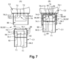
- the hydrogen supply device 28 comprises, for each first container C1, a housing 96 secured to the second container C2, positioned outside the latter and in which the second part 76.2, 74.2 of each connection system 66, 66' and of each connector 74 is positioned.
- the housing 96 is configured to house a part of the first container C1, more particularly its first compartment 94.1.
- the housing 96 comprises at least one second opening 82' positioned in line with the first opening 82 when the first and second containers C1, C2 are in the assembled state as well as a second hatch 84' configured to occupy a closed state in which it seals the second opening 82' and an open state in which it clears the second opening 82'.
- the hydrogen supply device 28 comprises at least one seal 98 interposed between, on the one hand, the first container C1 and, on the other hand, the second container C2 and/or the housing 96.
- the first container C1 is positioned facing the housing 96, as illustrated in part (A) of the Figure 7
- the first and second hatches 84, 84' are in the open state and clear the first and second openings 82, 82'.
- first container C1 is introduced into the housing 96 and then the first and second containers C1, C2 are assembled.
- the first and second parts 76.1, 74.1, 76.2, 74.2 of each connection system 66, 66' and of each connector 74 are connected, as illustrated in part (B) of the Figure 7 .
- the first and second hatches 84, 84' being in the open state, it is possible to access the first and second parts 76.1, 74.1, 76.2, 74.2 of each connection system 66, 66' and of each connector 74.
- first and second hatches 84, 84' are closed and a protective atmosphere is put in place in the first compartment 94.1 of the first container 94 by creating an appropriate vacuum or by injecting an inert gas.
- downstream containers 48 in which the second equipment 40 of the second category of equipment is positioned can be dismantled and removed from the aircraft without it being necessary to dismantle the hydrogen tank 30.
- This solution contributes to improving the maintenance of the downstream containers 48 and, ultimately, of the hydrogen supply device 28.
- connection systems 66, 66' and the connectors 74 outside the upstream and downstream containers 46, 48 makes it possible to ensure the sealing of the upstream and downstream containers 46 before their assembly. Since the conduits 42 and the connection systems 66, 66' present in the intermediate container 68 are all configured to ensure a high level of safety in terms of hydrogen leakage, the intermediate container 68 does not need to have a high seal and contain a protective atmosphere.
Landscapes
- Engineering & Computer Science (AREA)
- Aviation & Aerospace Engineering (AREA)
- Mechanical Engineering (AREA)
- General Engineering & Computer Science (AREA)
- Filling Or Discharging Of Gas Storage Vessels (AREA)
Claims (15)
- Luftfahrzeug mit wenigstens einer Wasserstoffversorgungsvorrichtung, die wenigstens einen mit dem Luftfahrzeug verbundenen Wasserstofftank (30), wenigstens eine Wasserstoffleitung (32.1 bis 32.4) sowie wenigstens einen mit dem Wasserstofftank (30) fest verbundenen stromaufwärts gelegenen Behälter (46) aufweist, dadurch gekennzeichnet, dass die Wasserstoffversorgungsvorrichtung wenigstens einen abnehmbaren stromabwärts gelegenen Behälter (48) aufweist, wobei die stromaufwärts und stromabwärts gelegenen Behälter (46, 48) so eingerichtet sind, dass sie einen zusammengebauten Zustand einnehmen, in dem die stromaufwärts und stromabwärts gelegenen Behälter (46, 48) miteinander verbunden sind, und einen abgebauten Zustand einnehmen, in dem die stromaufwärts und stromabwärts gelegenen Behälter (46, 48) voneinander getrennt sind, wobei die Wasserstoffleitung (32.1 bis 32.4) einen stromaufwärts gelegenen Abschnitt (62), der in dem stromaufwärts gelegenen Behälter (46) angeordnet ist, einen stromabwärts gelegenen Abschnitt (64), der in dem stromabwärts gelegenen Behälter (48) angeordnet ist, sowie ein erstes Verbindungssystem (66, 66') aufweist, das den stromaufwärts und den stromabwärts gelegenen Abschnitt (62, 64) verbindet, wenn sich der stromaufwärts und der stromabwärts gelegenen Behälter (46, 48) in dem zusammengebauten Zustand befinden.
- Luftfahrzeug nach Anspruch 1, dadurch gekennzeichnet, dass die stromaufwärts und stromabwärts gelegenen Behälter (46, 48) jeweils stromaufwärts und stromabwärts gelegene Verbindungsflächen (46.1, 48.1) aufweisen, die in einem Verbindungsbereich (50) angeordnet sind und im zusammengebauten Zustand nahe beieinander liegen, wobei das erste Verbindungssystem (66) nahe dem Verbindungsbereich (50) angeordnet ist, wenn sich die stromaufwärts und stromabwärts gelegenen Behälter (46, 48) im zusammengebauten Zustand befinden.
- Luftfahrzeug nach Anspruch 1, dadurch gekennzeichnet, dass die Wasserstoffversorgungsvorrichtung (28) wenigstens einen dazwischenliegenden Behälter (68) aufweist, der abnehmbar ist und zwischen den stromaufwärts und stromabwärts gelegenen Behältern (46, 48) angeordnet ist, wobei die stromaufwärts gelegenen und dazwischenliegende Behälter (46, 68) so eingerichtet sind, dass sie einen zusammengebauten Zustand einnehmen, in dem die stromaufwärts gelegenen und dazwischenliegenden Behälter (46, 68) in einem ersten Verbindungsbereich (50) aneinander angenähert sind, sowie einen abgebauten Zustand einnehmen, in dem die stromaufwärts gelegenen und dazwischenliegenden Behälter (46, 68) voneinander entfernt sind, wobei die stromabwärts gelegenen und dazwischenliegenden Behälter (48, 68) so eingerichtet sind, dass sie einen zusammengebauten Zustand einnehmen, in dem die stromabwärts gelegene und dazwischenliegenden Behälter (48, 68) in einem zweiten Verbindungsbereich (50') aneinander angenähert sind, sowie einen abgebauten Zustand einnehmen, in dem die stromabwärts gelegenen und dazwischenliegenden Behälter (48, 68) voneinander entfernt sind, wobei die Wasserstoffleitung (32.1 bis 32.4) einen dazwischenliegenden Abschnitt (70), der zwischen den stromaufwärts und stromabwärts gelegenen Abschnitten (62, 64) und in dem dazwischenliegenden Behälter (68) angeordnet ist, ein erstes Verbindungssystem (66), das den stromaufwärts gelgenen und den dazwischenliegenden Abschnitt (62, 70) verbindet und in dem ersten Verbindungsbereich (50) angeordnet ist, sowie ein zweites Verbindungssystem (66') aufweist, das den stromabwärts gelegenen und den dazwischenliegenden Abschnitt (64, 70) verbindet und in dem zweiten Verbindungsbereich (50') angeordnet ist.
- Luftfahrzeug nach dem vorhergehenden Anspruch, dadurch gekennzeichnet, dass die Wasserstoffversorgungseinrichtung wenigstens ein elektrisches Kabel (72) mit einem Abschnitt (72.1, 72.2) für jeden Behälter unter den stromaufwärts, stromabwärts und dazwischen liegenden Behältern (46, 48, 68), in dem das elektrische Kabel (72) vorhanden ist, sowie einen Verbinder (74) aufweist, der die verschiedenen Abschnitte (72.1, 72.2) paarweise verbindet.
- Luftfahrzeug nach einem der vorhergehenden Ansprüche, dadurch gekennzeichnet, dass jeder der stromaufwärts und stromabwärts gelegenen Behälter (46, 48) gasdicht ist und eine Schutzatmosphäre enthält.
- Luftfahrzeug nach einem der vorhergehenden Ansprüche, dadurch gekennzeichnet, dass für wenigstens einen Verbindungsbereich (50, 50') jedes Verbindungssystem (66, 66') einen ersten Teil (76.1) aufweist, der fest mit einem ersten Abschnitt (T1) aus einem stromaufwärts gelegenen Abschnitt (62), einem stromabwärts gelegenen Abschnitt (64) und, falls vorhanden, einem dazwischenliegenden Abschnitt (70) verbunden ist, der in einem ersten Behälter (C1) aus einem stromaufwärts gelegenen Behälter (46), einem stromabwärts gelegenen Behälter (48) und, falls vorhanden, einem dazwischenliegenden Behälter (68) angeordnet ist, sowie einem zweiten Teil (76.2) aufweist, der fest mit einem zweiten Abschnitt (T2) aus einem stromaufwärts gelegenen Abschnitt (62), einem stromabwärts gelegenen Abschnitt (64) und, falls vorhanden, einem dazwischenliegenden Abschnitt (70) verbunden ist, der in einem zweiten Behälter (C2) aus einem stromaufwärts gelegenen Behälter (46), einem stromabwärts gelegenen Behälter (48) und, falls vorhanden, einem dazwischenliegenden Behälter (68) angeordnet ist; wobei der erste und der zweite Teil (76.1, 76.2) so eingerichtet sind, dass sie einen verbundenen Zustand einnehmen, in dem der erste und der zweite Teil (76.1, 76.2) zusammenwirken und eine Fluidkontinuität zwischen dem ersten und dem zweiten Abschnitt (T1, T2) sicherstellen, sowie einen unverbundenen Zustand einnehmen, in dem der erste und der zweite Teil (76.1, 76.2) beabstandet sind, und dass der erste und der zweite Behälter (C1, C2) eine erste und eine zweite Wand aufweisen, die aneinander angenähert sind, wenn sich der erste und der zweite Behälter (C1, C2) in einem zusammengebauten Zustand befinden.
- Luftfahrzeug nach dem vorhergehenden Anspruch, dadurch gekennzeichnet, dass der erste Teil (76.1) jedes Verbindungssystems (66, 66') an der ersten Wand (78.1) angeordnet und dicht mit dieser verbunden ist, und dass der zweite Teil (76.2) jedes Verbindungssystems (66, 66') an der zweiten Wand (78.2) angeordnet und dicht mit dieser verbunden ist.
- Luftfahrzeug nach Anspruch 6, dadurch gekennzeichnet, dass der erste Teil (76.1) jedes Verbindungssystems (66, 66') außerhalb des ersten Behälters (C1) angeordnet ist, wobei der erste Abschnitt (T1), der mit dem ersten Teil (76.1) verbunden ist, dicht durch die erste Wand (78.1) hindurchgeht, und dass der zweite Teil (76.2) jedes Verbindungssystems (66, 66') innerhalb des zweiten Behälters (C2) angeordnet ist, wobei die zweite Wand (78.2) des zweiten Behälters (C2) wenigstens eine Öffnung (80) aufweist, die so eingerichtet ist, dass der erste Teil (76.1) jedes Verbindungssystems (66, 66') in den zweiten Behälter (C2) eindringen kann.
- Luftfahrzeug nach Anspruch 6, dadurch gekennzeichnet, dass der erste Teil (76.1) jedes Verbindungssystems (66, 66') außerhalb des ersten Behälters (C1) angeordnet ist, wobei der erste Abschnitt (T1), der mit dem ersten Teil (76.1) verbunden ist, dicht durch die erste Wand (78.1) hindurchgeht, dass der zweite Teil (76.2) jedes Verbindungssystems (66, 66') innerhalb des zweiten Behälters (C2) angeordnet ist, wobei die zweite Wand (78.2) des zweiten Behälters (C2) wenigstens eine Öffnung (80) aufweist, die so eingerichtet ist, dass der erste Behälter (C1) in dem zweiten Behälter (C2) angeordnet werden kann, und dass die Wasserstoffversorgungsvorrichtung eine Platte (88) umfasst, die so eingerichtet ist, dass sie die Öffnung (80) gasdicht verschließt.
- Luftfahrzeug nach Anspruch 8 oder 9, dadurch gekennzeichnet, dass der zweite Behälter (C2) wenigstens eine Öffnung (82) aufweist, die so angeordnet ist, dass sie von einem äußeren Bereich des zweiten Behälters (C2) zu den Verbindungssystemen (66, 66') Zugang gewährt, sowie eine Klappe (84) umfasst, die so eingerichtet ist, dass sie einen geschlossenen Zustand einnimmt, in dem die Klappe (84) die Öffnung (82) dicht verschließt, und einen offenen Zustand einnimmt, in dem die Klappe (84) die Öffnung (82) freigibt.
- Luftfahrzeug nach Anspruch 6, dadurch gekennzeichnet, dass der erste Behälter (C1) eine Trennwand (92) aufweist, die den ersten Behälter (C1) in eine erste Kammer (94.1), die sich zwischen der Trennwand (92) und der ersten Wand (78.1) befindet, sowie eine zweite Kammer (94.2) unterteilt, die von der ersten Wand (78.1) beabstandet ist, dass der erste Teil (76.1) jedes Verbindungssystems (66, 66') in der ersten Kammer (94.1) angeordnet ist, wobei der erste Abschnitt (T1), der mit dem ersten Teil (76.1) verbunden ist, dicht durch die Trennwand (92) verläuft, und dass die erste Wand (78.1) wenigstens eine Öffnung (80) aufweist, um es dem zweiten Teil (76.2) jedes Verbindungssystems (66, 66') des zweiten Behälters (C2) zu ermöglichen, in die erste Kammer (94.1) einzudringen.
- Luftfahrzeug nach dem vorhergehenden Anspruch, dadurch gekennzeichnet, dass der erste Behälter (C1) wenigstens eine erste Öffnung (82) aufweist, die so angeordnet ist, dass sie von einem äußeren Bereich des ersten Behälters (C1) Zugang zu den Verbindungssystemen (66, 66') gewährt, sowie eine erste Klappe (84) aufweist, die so eingerichtet ist, dass sie einen geschlossenen Zustand einnimmt, in dem die erste Klappe (84) die erste Öffnung (82) dicht verschließt, und einen offenen Zustand einnimmt, in dem die erste Klappe (84) die erste Öffnung (82) freigibt.
- Luftfahrzeug nach Anspruch 11 oder 12, dadurch gekennzeichnet, dass die Wasserstoffversorgungseinrichtung für jeden ersten Behälter (C1) eine Aufnahme (96) aufweist, die fest mit dem zweiten Behälter (C2) verbunden ist und in der der zweite Teil (76.2) jedes Verbindungssystems (66, 66') angeordnet ist, wobei diese Aufnahme (96) so eingerichtet ist, dass sie einen Teil des ersten Behälters (C1) aufnimmt.
- Luftfahrzeug nach den Ansprüchen 12 und 13, dadurch gekennzeichnet, dass das Gehäuse (96) wenigstens eine zweite Öffnung (82') aufweist, die am Ort der ersten Öffnung (82) angeordnet ist, wenn sich der erste und der zweite Behälter (C1, C2) im zusammengebauten Zustand befinden, sowie eine zweite Klappe (84') aufweist, die so eingerichtet ist, dass sie einen geschlossenen Zustand einnimmt, in dem die zweite Klappe (84') die zweite Öffnung (82') dicht verschließt, und einen offenen Zustand einnimmt, in dem die zweite Klappe (84') die zweite Öffnung (82') freigibt.
- Luftfahrzeug nach Anspruch 13 oder 14, dadurch gekennzeichnet, dass die Wasserstoffversorgungsvorrichtung wenigstens eine Dichtung (98) aufweist, die zwischen einerseits dem ersten Behälter (C1) und andererseits dem zweiten Behälter (C2) und/oder dem Gehäuse (96) eingefügt ist.
Applications Claiming Priority (1)
| Application Number | Priority Date | Filing Date | Title |
|---|---|---|---|
| FR2212738 | 2022-12-05 |
Publications (2)
| Publication Number | Publication Date |
|---|---|
| EP4382433A1 EP4382433A1 (de) | 2024-06-12 |
| EP4382433B1 true EP4382433B1 (de) | 2025-06-18 |
Family
ID=85122128
Family Applications (1)
| Application Number | Title | Priority Date | Filing Date |
|---|---|---|---|
| EP23209277.5A Active EP4382433B1 (de) | 2022-12-05 | 2023-11-11 | Luftfahrzeug mit mindestens einer wasserstoffversorgungsvorrichtung mit einem wasserstoffspeicher sowie in mindestens einem speicherfesten behälter und mindestens einem abnehmbaren behälter verteilt angeordneten einrichtungen |
Country Status (3)
| Country | Link |
|---|---|
| US (1) | US12565965B2 (de) |
| EP (1) | EP4382433B1 (de) |
| CN (1) | CN118149273A (de) |
Family Cites Families (5)
| Publication number | Priority date | Publication date | Assignee | Title |
|---|---|---|---|---|
| GB201105340D0 (en) * | 2011-03-30 | 2011-05-11 | Airbus Operations Ltd | Conduit protection system and method |
| DE102012023531B4 (de) * | 2012-11-30 | 2014-07-31 | Diehl Aerospace Gmbh | Verfahren zur Versorgung der Kabine eines Fahrzeugs mit einem Betriebsstoff |
| WO2015040268A1 (en) * | 2013-09-20 | 2015-03-26 | Wärtsilä Finland Oy | Novel arrangement of access to lng fuel storage compartment |
| FR3094070B1 (fr) * | 2019-03-21 | 2021-10-15 | Air Liquide | Dispositif et procédé de stockage et de fourniture de carburant fluide. |
| FR3119489A1 (fr) * | 2021-01-29 | 2022-08-05 | Airbus Operations (S.A.S.) | Dispositif de regroupement de piles à combustible comportant un support configuré pour alimenter en fluide les piles à combustible, aéronef comportant au moins un tel dispositif de regroupement de piles à combustible |
-
2023
- 2023-11-11 EP EP23209277.5A patent/EP4382433B1/de active Active
- 2023-11-30 CN CN202311625839.XA patent/CN118149273A/zh active Pending
- 2023-12-01 US US18/525,938 patent/US12565965B2/en active Active
Also Published As
| Publication number | Publication date |
|---|---|
| CN118149273A (zh) | 2024-06-07 |
| EP4382433A1 (de) | 2024-06-12 |
| US20240183493A1 (en) | 2024-06-06 |
| US12565965B2 (en) | 2026-03-03 |
Similar Documents
| Publication | Publication Date | Title |
|---|---|---|
| EP4174357B1 (de) | Optimierte verbindungsanordnung zwischen zwei abschnitten einer rohrleitung zum transport eines kryogenen fluids mit einer zusätzlichen wärmedämmkammer und einer flüssigkeitsexpansionskammer | |
| EP4129827B1 (de) | Luftfahrzeug mit mindestens einer vorrichtung zur wasserstoffversorgung sowie mindestens einem dichten behälter, in dem mindestens ein ausrüstungsteil der vorrichtung zur wasserstoffversorgung positioniert ist | |
| EP4155597B1 (de) | Wasserstoffleitung mit doppelter wand mit mindestens einem system zur erkennung von lecks an mindestens einem verbindungssystem, luftfahrzeug mit mindestens einer solchen leitung | |
| EP1265035B1 (de) | Doppelbefestigung einer Turbinenbrennkammer aus keramischem Matrix-Verbundwerkstoff | |
| EP2534406A1 (de) | Verbundtank und anordnung mit einem solchen tank sowie element zur aufnahme und/oder ausgabe von gas | |
| CA2880859C (fr) | Rampe d'injection modulaire a double circuit | |
| EP1607682B1 (de) | Gasturbine | |
| FR2698914A1 (fr) | Moteur-fusée à ergols liquides à flux dérivé et générateur de gaz intégré. | |
| WO2003040524A1 (fr) | Stator pour turbomachine | |
| EP4130635B1 (de) | Wärmetauscher, der das risiko einer kontamination zwischen zwei fluiden begrenzt, und luftfahrzeug mit mindestens einem solchen wärmetauscher | |
| FR2706540A1 (fr) | Pompe liquide cryogénique intégrée amovible et autorefroidie. | |
| FR2658578A1 (fr) | Dispositif a soupape d'arret evitant les fuites. | |
| EP0895017A1 (de) | Tank für unter Druck stehende Fluide | |
| EP4382433B1 (de) | Luftfahrzeug mit mindestens einer wasserstoffversorgungsvorrichtung mit einem wasserstoffspeicher sowie in mindestens einem speicherfesten behälter und mindestens einem abnehmbaren behälter verteilt angeordneten einrichtungen | |
| EP0374020B1 (de) | Kompakte Hochdruckturbopumpe zur Versorgung eines Raketenmotors mit Treibstoff | |
| EP4083489B1 (de) | Anschluss | |
| WO2021255000A1 (fr) | Dôme liquide d'une cuve de stockage pour gaz liquéfié | |
| FR2735085A1 (fr) | Systeme de tuyauterie pour le remplissage en carburant liquide d'une cuve enterree et pour le transfert de ce carburant vers un poste de distribution | |
| EP3642115B1 (de) | Verbesserter tank für raumfahrzeugtriebwerk | |
| FR2998634A1 (fr) | Vanne a obturateur spherique, notamment pour turbine a gaz | |
| EP4455021B1 (de) | Flugzeug mit mindestens einer wasserstoffversorgungsvorrichtung mit mindestens einem gasabführungssystem im falle eines lecks | |
| EP3388661B1 (de) | Deckel für kraftstoffeinfüllstutzen mit kraftstoffrücklauf | |
| EP4361492B1 (de) | Vorrichtung zur lagerung einer kryogenen flüssigkeit | |
| EP4174355B1 (de) | Optimierte verbindungsanordnung zwischen zwei teilen einer kryogenen rohrleitung mit doppelter dichtungsbarriere, flüssigkeitsexpansionskammer und einem sensor zur bestimmung der flüssigkeit in dieser kammer | |
| FR2869367A1 (fr) | Dispositif de raccordement d'un tube d'injection de carburant sous pression |
Legal Events
| Date | Code | Title | Description |
|---|---|---|---|
| PUAI | Public reference made under article 153(3) epc to a published international application that has entered the european phase |
Free format text: ORIGINAL CODE: 0009012 |
|
| STAA | Information on the status of an ep patent application or granted ep patent |
Free format text: STATUS: THE APPLICATION HAS BEEN PUBLISHED |
|
| AK | Designated contracting states |
Kind code of ref document: A1 Designated state(s): AL AT BE BG CH CY CZ DE DK EE ES FI FR GB GR HR HU IE IS IT LI LT LU LV MC ME MK MT NL NO PL PT RO RS SE SI SK SM TR |
|
| STAA | Information on the status of an ep patent application or granted ep patent |
Free format text: STATUS: REQUEST FOR EXAMINATION WAS MADE |
|
| 17P | Request for examination filed |
Effective date: 20241125 |
|
| RBV | Designated contracting states (corrected) |
Designated state(s): AL AT BE BG CH CY CZ DE DK EE ES FI FR GB GR HR HU IE IS IT LI LT LU LV MC ME MK MT NL NO PL PT RO RS SE SI SK SM TR |
|
| RIC1 | Information provided on ipc code assigned before grant |
Ipc: F17C 13/08 20060101ALI20241211BHEP Ipc: F17C 13/00 20060101ALI20241211BHEP Ipc: B64D 37/32 20060101ALI20241211BHEP Ipc: B64D 37/30 20060101ALI20241211BHEP Ipc: B64D 37/20 20060101AFI20241211BHEP |
|
| GRAP | Despatch of communication of intention to grant a patent |
Free format text: ORIGINAL CODE: EPIDOSNIGR1 |
|
| STAA | Information on the status of an ep patent application or granted ep patent |
Free format text: STATUS: GRANT OF PATENT IS INTENDED |
|
| INTG | Intention to grant announced |
Effective date: 20250128 |
|
| GRAS | Grant fee paid |
Free format text: ORIGINAL CODE: EPIDOSNIGR3 |
|
| GRAA | (expected) grant |
Free format text: ORIGINAL CODE: 0009210 |
|
| STAA | Information on the status of an ep patent application or granted ep patent |
Free format text: STATUS: THE PATENT HAS BEEN GRANTED |
|
| AK | Designated contracting states |
Kind code of ref document: B1 Designated state(s): AL AT BE BG CH CY CZ DE DK EE ES FI FR GB GR HR HU IE IS IT LI LT LU LV MC ME MK MT NL NO PL PT RO RS SE SI SK SM TR |
|
| REG | Reference to a national code |
Ref country code: GB Ref legal event code: FG4D Free format text: NOT ENGLISH |
|
| REG | Reference to a national code |
Ref country code: CH Ref legal event code: EP |
|
| REG | Reference to a national code |
Ref country code: DE Ref legal event code: R096 Ref document number: 602023004096 Country of ref document: DE |
|
| REG | Reference to a national code |
Ref country code: CH Ref legal event code: EP |
|
| REG | Reference to a national code |
Ref country code: IE Ref legal event code: FG4D Free format text: LANGUAGE OF EP DOCUMENT: FRENCH |
|
| PG25 | Lapsed in a contracting state [announced via postgrant information from national office to epo] |
Ref country code: FI Free format text: LAPSE BECAUSE OF FAILURE TO SUBMIT A TRANSLATION OF THE DESCRIPTION OR TO PAY THE FEE WITHIN THE PRESCRIBED TIME-LIMIT Effective date: 20250618 |
|
| REG | Reference to a national code |
Ref country code: LT Ref legal event code: MG9D |
|
| PG25 | Lapsed in a contracting state [announced via postgrant information from national office to epo] |
Ref country code: GR Free format text: LAPSE BECAUSE OF FAILURE TO SUBMIT A TRANSLATION OF THE DESCRIPTION OR TO PAY THE FEE WITHIN THE PRESCRIBED TIME-LIMIT Effective date: 20250919 Ref country code: NO Free format text: LAPSE BECAUSE OF FAILURE TO SUBMIT A TRANSLATION OF THE DESCRIPTION OR TO PAY THE FEE WITHIN THE PRESCRIBED TIME-LIMIT Effective date: 20250918 |
|
| PG25 | Lapsed in a contracting state [announced via postgrant information from national office to epo] |
Ref country code: BG Free format text: LAPSE BECAUSE OF FAILURE TO SUBMIT A TRANSLATION OF THE DESCRIPTION OR TO PAY THE FEE WITHIN THE PRESCRIBED TIME-LIMIT Effective date: 20250618 |
|
| PG25 | Lapsed in a contracting state [announced via postgrant information from national office to epo] |
Ref country code: HR Free format text: LAPSE BECAUSE OF FAILURE TO SUBMIT A TRANSLATION OF THE DESCRIPTION OR TO PAY THE FEE WITHIN THE PRESCRIBED TIME-LIMIT Effective date: 20250618 |
|
| PG25 | Lapsed in a contracting state [announced via postgrant information from national office to epo] |
Ref country code: RS Free format text: LAPSE BECAUSE OF FAILURE TO SUBMIT A TRANSLATION OF THE DESCRIPTION OR TO PAY THE FEE WITHIN THE PRESCRIBED TIME-LIMIT Effective date: 20250918 |
|
| REG | Reference to a national code |
Ref country code: NL Ref legal event code: MP Effective date: 20250618 |
|
| PG25 | Lapsed in a contracting state [announced via postgrant information from national office to epo] |
Ref country code: LV Free format text: LAPSE BECAUSE OF FAILURE TO SUBMIT A TRANSLATION OF THE DESCRIPTION OR TO PAY THE FEE WITHIN THE PRESCRIBED TIME-LIMIT Effective date: 20250618 |
|
| PG25 | Lapsed in a contracting state [announced via postgrant information from national office to epo] |
Ref country code: NL Free format text: LAPSE BECAUSE OF FAILURE TO SUBMIT A TRANSLATION OF THE DESCRIPTION OR TO PAY THE FEE WITHIN THE PRESCRIBED TIME-LIMIT Effective date: 20250618 |
|
| PG25 | Lapsed in a contracting state [announced via postgrant information from national office to epo] |
Ref country code: PT Free format text: LAPSE BECAUSE OF FAILURE TO SUBMIT A TRANSLATION OF THE DESCRIPTION OR TO PAY THE FEE WITHIN THE PRESCRIBED TIME-LIMIT Effective date: 20251020 |
|
| REG | Reference to a national code |
Ref country code: AT Ref legal event code: MK05 Ref document number: 1803997 Country of ref document: AT Kind code of ref document: T Effective date: 20250618 |
|
| PG25 | Lapsed in a contracting state [announced via postgrant information from national office to epo] |
Ref country code: IS Free format text: LAPSE BECAUSE OF FAILURE TO SUBMIT A TRANSLATION OF THE DESCRIPTION OR TO PAY THE FEE WITHIN THE PRESCRIBED TIME-LIMIT Effective date: 20251018 |
|
| PGFP | Annual fee paid to national office [announced via postgrant information from national office to epo] |
Ref country code: DE Payment date: 20251119 Year of fee payment: 3 |
|
| PG25 | Lapsed in a contracting state [announced via postgrant information from national office to epo] |
Ref country code: AT Free format text: LAPSE BECAUSE OF FAILURE TO SUBMIT A TRANSLATION OF THE DESCRIPTION OR TO PAY THE FEE WITHIN THE PRESCRIBED TIME-LIMIT Effective date: 20250618 Ref country code: SM Free format text: LAPSE BECAUSE OF FAILURE TO SUBMIT A TRANSLATION OF THE DESCRIPTION OR TO PAY THE FEE WITHIN THE PRESCRIBED TIME-LIMIT Effective date: 20250618 |
|
| PGFP | Annual fee paid to national office [announced via postgrant information from national office to epo] |
Ref country code: FR Payment date: 20251126 Year of fee payment: 3 |
|
| PG25 | Lapsed in a contracting state [announced via postgrant information from national office to epo] |
Ref country code: CZ Free format text: LAPSE BECAUSE OF FAILURE TO SUBMIT A TRANSLATION OF THE DESCRIPTION OR TO PAY THE FEE WITHIN THE PRESCRIBED TIME-LIMIT Effective date: 20250618 |
|
| PG25 | Lapsed in a contracting state [announced via postgrant information from national office to epo] |
Ref country code: PL Free format text: LAPSE BECAUSE OF FAILURE TO SUBMIT A TRANSLATION OF THE DESCRIPTION OR TO PAY THE FEE WITHIN THE PRESCRIBED TIME-LIMIT Effective date: 20250618 |
|
| PG25 | Lapsed in a contracting state [announced via postgrant information from national office to epo] |
Ref country code: EE Free format text: LAPSE BECAUSE OF FAILURE TO SUBMIT A TRANSLATION OF THE DESCRIPTION OR TO PAY THE FEE WITHIN THE PRESCRIBED TIME-LIMIT Effective date: 20250618 |
|
| PG25 | Lapsed in a contracting state [announced via postgrant information from national office to epo] |
Ref country code: SK Free format text: LAPSE BECAUSE OF FAILURE TO SUBMIT A TRANSLATION OF THE DESCRIPTION OR TO PAY THE FEE WITHIN THE PRESCRIBED TIME-LIMIT Effective date: 20250618 |
|
| PG25 | Lapsed in a contracting state [announced via postgrant information from national office to epo] |
Ref country code: ES Free format text: LAPSE BECAUSE OF FAILURE TO SUBMIT A TRANSLATION OF THE DESCRIPTION OR TO PAY THE FEE WITHIN THE PRESCRIBED TIME-LIMIT Effective date: 20250618 |
|
| PG25 | Lapsed in a contracting state [announced via postgrant information from national office to epo] |
Ref country code: RO Free format text: LAPSE BECAUSE OF FAILURE TO SUBMIT A TRANSLATION OF THE DESCRIPTION OR TO PAY THE FEE WITHIN THE PRESCRIBED TIME-LIMIT Effective date: 20250618 |