EP4155597B1 - Wasserstoffleitung mit doppelter wand mit mindestens einem system zur erkennung von lecks an mindestens einem verbindungssystem, luftfahrzeug mit mindestens einer solchen leitung - Google Patents
Wasserstoffleitung mit doppelter wand mit mindestens einem system zur erkennung von lecks an mindestens einem verbindungssystem, luftfahrzeug mit mindestens einer solchen leitung Download PDFInfo
- Publication number
- EP4155597B1 EP4155597B1 EP22194723.7A EP22194723A EP4155597B1 EP 4155597 B1 EP4155597 B1 EP 4155597B1 EP 22194723 A EP22194723 A EP 22194723A EP 4155597 B1 EP4155597 B1 EP 4155597B1
- Authority
- EP
- European Patent Office
- Prior art keywords
- upstream
- downstream
- pipeline
- annular seal
- section
- Prior art date
- Legal status (The legal status is an assumption and is not a legal conclusion. Google has not performed a legal analysis and makes no representation as to the accuracy of the status listed.)
- Active
Links
Images

Classifications
-
- F—MECHANICAL ENGINEERING; LIGHTING; HEATING; WEAPONS; BLASTING
- F16—ENGINEERING ELEMENTS AND UNITS; GENERAL MEASURES FOR PRODUCING AND MAINTAINING EFFECTIVE FUNCTIONING OF MACHINES OR INSTALLATIONS; THERMAL INSULATION IN GENERAL
- F16L—PIPES; JOINTS OR FITTINGS FOR PIPES; SUPPORTS FOR PIPES, CABLES OR PROTECTIVE TUBING; MEANS FOR THERMAL INSULATION IN GENERAL
- F16L51/00—Expansion-compensation arrangements for pipe-lines
-
- B—PERFORMING OPERATIONS; TRANSPORTING
- B64—AIRCRAFT; AVIATION; COSMONAUTICS
- B64D—EQUIPMENT FOR FITTING IN OR TO AIRCRAFT; FLIGHT SUITS; PARACHUTES; ARRANGEMENT OR MOUNTING OF POWER PLANTS OR PROPULSION TRANSMISSIONS IN AIRCRAFT
- B64D37/00—Arrangements in connection with fuel supply for power plant
- B64D37/005—Accessories not provided for in the groups B64D37/02 - B64D37/28
-
- B—PERFORMING OPERATIONS; TRANSPORTING
- B64—AIRCRAFT; AVIATION; COSMONAUTICS
- B64D—EQUIPMENT FOR FITTING IN OR TO AIRCRAFT; FLIGHT SUITS; PARACHUTES; ARRANGEMENT OR MOUNTING OF POWER PLANTS OR PROPULSION TRANSMISSIONS IN AIRCRAFT
- B64D37/00—Arrangements in connection with fuel supply for power plant
- B64D37/30—Fuel systems for specific fuels
-
- B—PERFORMING OPERATIONS; TRANSPORTING
- B64—AIRCRAFT; AVIATION; COSMONAUTICS
- B64D—EQUIPMENT FOR FITTING IN OR TO AIRCRAFT; FLIGHT SUITS; PARACHUTES; ARRANGEMENT OR MOUNTING OF POWER PLANTS OR PROPULSION TRANSMISSIONS IN AIRCRAFT
- B64D37/00—Arrangements in connection with fuel supply for power plant
- B64D37/32—Safety measures not otherwise provided for, e.g. preventing explosive conditions
-
- F—MECHANICAL ENGINEERING; LIGHTING; HEATING; WEAPONS; BLASTING
- F16—ENGINEERING ELEMENTS AND UNITS; GENERAL MEASURES FOR PRODUCING AND MAINTAINING EFFECTIVE FUNCTIONING OF MACHINES OR INSTALLATIONS; THERMAL INSULATION IN GENERAL
- F16J—PISTONS; CYLINDERS; SEALINGS
- F16J15/00—Sealings
- F16J15/02—Sealings between relatively-stationary surfaces
- F16J15/06—Sealings between relatively-stationary surfaces with solid packing compressed between sealing surfaces
- F16J15/08—Sealings between relatively-stationary surfaces with solid packing compressed between sealing surfaces with exclusively metal packing
- F16J15/0887—Sealings between relatively-stationary surfaces with solid packing compressed between sealing surfaces with exclusively metal packing the sealing effect being obtained by elastic deformation of the packing
-
- F—MECHANICAL ENGINEERING; LIGHTING; HEATING; WEAPONS; BLASTING
- F16—ENGINEERING ELEMENTS AND UNITS; GENERAL MEASURES FOR PRODUCING AND MAINTAINING EFFECTIVE FUNCTIONING OF MACHINES OR INSTALLATIONS; THERMAL INSULATION IN GENERAL
- F16J—PISTONS; CYLINDERS; SEALINGS
- F16J15/00—Sealings
- F16J15/02—Sealings between relatively-stationary surfaces
- F16J15/06—Sealings between relatively-stationary surfaces with solid packing compressed between sealing surfaces
- F16J15/10—Sealings between relatively-stationary surfaces with solid packing compressed between sealing surfaces with non-metallic packing
- F16J15/104—Sealings between relatively-stationary surfaces with solid packing compressed between sealing surfaces with non-metallic packing characterised by structure
- F16J15/106—Sealings between relatively-stationary surfaces with solid packing compressed between sealing surfaces with non-metallic packing characterised by structure homogeneous
-
- F—MECHANICAL ENGINEERING; LIGHTING; HEATING; WEAPONS; BLASTING
- F16—ENGINEERING ELEMENTS AND UNITS; GENERAL MEASURES FOR PRODUCING AND MAINTAINING EFFECTIVE FUNCTIONING OF MACHINES OR INSTALLATIONS; THERMAL INSULATION IN GENERAL
- F16J—PISTONS; CYLINDERS; SEALINGS
- F16J15/00—Sealings
- F16J15/46—Sealings with packing ring expanded or pressed into place by fluid pressure, e.g. inflatable packings
- F16J15/48—Sealings with packing ring expanded or pressed into place by fluid pressure, e.g. inflatable packings influenced by the pressure within the member to be sealed
-
- F—MECHANICAL ENGINEERING; LIGHTING; HEATING; WEAPONS; BLASTING
- F16—ENGINEERING ELEMENTS AND UNITS; GENERAL MEASURES FOR PRODUCING AND MAINTAINING EFFECTIVE FUNCTIONING OF MACHINES OR INSTALLATIONS; THERMAL INSULATION IN GENERAL
- F16L—PIPES; JOINTS OR FITTINGS FOR PIPES; SUPPORTS FOR PIPES, CABLES OR PROTECTIVE TUBING; MEANS FOR THERMAL INSULATION IN GENERAL
- F16L17/00—Joints with packing adapted to sealing by fluid pressure
- F16L17/02—Joints with packing adapted to sealing by fluid pressure with sealing rings arranged between outer surface of pipe and inner surface of sleeve or socket
- F16L17/03—Joints with packing adapted to sealing by fluid pressure with sealing rings arranged between outer surface of pipe and inner surface of sleeve or socket having annular axial lips
- F16L17/035—Joints with packing adapted to sealing by fluid pressure with sealing rings arranged between outer surface of pipe and inner surface of sleeve or socket having annular axial lips the sealing rings having two lips parallel to each other
-
- F—MECHANICAL ENGINEERING; LIGHTING; HEATING; WEAPONS; BLASTING
- F16—ENGINEERING ELEMENTS AND UNITS; GENERAL MEASURES FOR PRODUCING AND MAINTAINING EFFECTIVE FUNCTIONING OF MACHINES OR INSTALLATIONS; THERMAL INSULATION IN GENERAL
- F16L—PIPES; JOINTS OR FITTINGS FOR PIPES; SUPPORTS FOR PIPES, CABLES OR PROTECTIVE TUBING; MEANS FOR THERMAL INSULATION IN GENERAL
- F16L17/00—Joints with packing adapted to sealing by fluid pressure
- F16L17/06—Joints with packing adapted to sealing by fluid pressure with sealing rings arranged between the end surfaces of the pipes or flanges or arranged in recesses in the pipe ends or flanges
-
- F—MECHANICAL ENGINEERING; LIGHTING; HEATING; WEAPONS; BLASTING
- F16—ENGINEERING ELEMENTS AND UNITS; GENERAL MEASURES FOR PRODUCING AND MAINTAINING EFFECTIVE FUNCTIONING OF MACHINES OR INSTALLATIONS; THERMAL INSULATION IN GENERAL
- F16L—PIPES; JOINTS OR FITTINGS FOR PIPES; SUPPORTS FOR PIPES, CABLES OR PROTECTIVE TUBING; MEANS FOR THERMAL INSULATION IN GENERAL
- F16L39/00—Joints or fittings for double-walled or multi-channel pipes or pipe assemblies
- F16L39/005—Joints or fittings for double-walled or multi-channel pipes or pipe assemblies for concentric pipes
-
- F—MECHANICAL ENGINEERING; LIGHTING; HEATING; WEAPONS; BLASTING
- F16—ENGINEERING ELEMENTS AND UNITS; GENERAL MEASURES FOR PRODUCING AND MAINTAINING EFFECTIVE FUNCTIONING OF MACHINES OR INSTALLATIONS; THERMAL INSULATION IN GENERAL
- F16L—PIPES; JOINTS OR FITTINGS FOR PIPES; SUPPORTS FOR PIPES, CABLES OR PROTECTIVE TUBING; MEANS FOR THERMAL INSULATION IN GENERAL
- F16L51/00—Expansion-compensation arrangements for pipe-lines
- F16L51/02—Expansion-compensation arrangements for pipe-lines making use of a bellows or an expansible folded or corrugated tube
- F16L51/025—Expansion-compensation arrangements for pipe-lines making use of a bellows or an expansible folded or corrugated tube with several corrugations
-
- G—PHYSICS
- G01—MEASURING; TESTING
- G01M—TESTING STATIC OR DYNAMIC BALANCE OF MACHINES OR STRUCTURES; TESTING OF STRUCTURES OR APPARATUS, NOT OTHERWISE PROVIDED FOR
- G01M3/00—Investigating fluid-tightness of structures
- G01M3/02—Investigating fluid-tightness of structures by using fluid or vacuum
- G01M3/26—Investigating fluid-tightness of structures by using fluid or vacuum by measuring rate of loss or gain of fluid, e.g. by pressure-responsive devices, by flow detectors
- G01M3/28—Investigating fluid-tightness of structures by using fluid or vacuum by measuring rate of loss or gain of fluid, e.g. by pressure-responsive devices, by flow detectors for pipes, cables or tubes; for pipe joints or seals; for valves ; for welds
- G01M3/2807—Investigating fluid-tightness of structures by using fluid or vacuum by measuring rate of loss or gain of fluid, e.g. by pressure-responsive devices, by flow detectors for pipes, cables or tubes; for pipe joints or seals; for valves ; for welds for pipes
- G01M3/2815—Investigating fluid-tightness of structures by using fluid or vacuum by measuring rate of loss or gain of fluid, e.g. by pressure-responsive devices, by flow detectors for pipes, cables or tubes; for pipe joints or seals; for valves ; for welds for pipes using pressure measurements
-
- G—PHYSICS
- G01—MEASURING; TESTING
- G01M—TESTING STATIC OR DYNAMIC BALANCE OF MACHINES OR STRUCTURES; TESTING OF STRUCTURES OR APPARATUS, NOT OTHERWISE PROVIDED FOR
- G01M3/00—Investigating fluid-tightness of structures
- G01M3/02—Investigating fluid-tightness of structures by using fluid or vacuum
- G01M3/26—Investigating fluid-tightness of structures by using fluid or vacuum by measuring rate of loss or gain of fluid, e.g. by pressure-responsive devices, by flow detectors
- G01M3/28—Investigating fluid-tightness of structures by using fluid or vacuum by measuring rate of loss or gain of fluid, e.g. by pressure-responsive devices, by flow detectors for pipes, cables or tubes; for pipe joints or seals; for valves ; for welds
- G01M3/2807—Investigating fluid-tightness of structures by using fluid or vacuum by measuring rate of loss or gain of fluid, e.g. by pressure-responsive devices, by flow detectors for pipes, cables or tubes; for pipe joints or seals; for valves ; for welds for pipes
- G01M3/283—Investigating fluid-tightness of structures by using fluid or vacuum by measuring rate of loss or gain of fluid, e.g. by pressure-responsive devices, by flow detectors for pipes, cables or tubes; for pipe joints or seals; for valves ; for welds for pipes for double-walled pipes
-
- F—MECHANICAL ENGINEERING; LIGHTING; HEATING; WEAPONS; BLASTING
- F16—ENGINEERING ELEMENTS AND UNITS; GENERAL MEASURES FOR PRODUCING AND MAINTAINING EFFECTIVE FUNCTIONING OF MACHINES OR INSTALLATIONS; THERMAL INSULATION IN GENERAL
- F16L—PIPES; JOINTS OR FITTINGS FOR PIPES; SUPPORTS FOR PIPES, CABLES OR PROTECTIVE TUBING; MEANS FOR THERMAL INSULATION IN GENERAL
- F16L17/00—Joints with packing adapted to sealing by fluid pressure
- F16L17/06—Joints with packing adapted to sealing by fluid pressure with sealing rings arranged between the end surfaces of the pipes or flanges or arranged in recesses in the pipe ends or flanges
- F16L17/067—Plastics sealing rings
- F16L17/073—Plastics sealing rings the sealing rings having two lips parallel to each other
-
- F—MECHANICAL ENGINEERING; LIGHTING; HEATING; WEAPONS; BLASTING
- F16—ENGINEERING ELEMENTS AND UNITS; GENERAL MEASURES FOR PRODUCING AND MAINTAINING EFFECTIVE FUNCTIONING OF MACHINES OR INSTALLATIONS; THERMAL INSULATION IN GENERAL
- F16L—PIPES; JOINTS OR FITTINGS FOR PIPES; SUPPORTS FOR PIPES, CABLES OR PROTECTIVE TUBING; MEANS FOR THERMAL INSULATION IN GENERAL
- F16L2201/00—Special arrangements for pipe couplings
- F16L2201/30—Detecting leaks
-
- F—MECHANICAL ENGINEERING; LIGHTING; HEATING; WEAPONS; BLASTING
- F16—ENGINEERING ELEMENTS AND UNITS; GENERAL MEASURES FOR PRODUCING AND MAINTAINING EFFECTIVE FUNCTIONING OF MACHINES OR INSTALLATIONS; THERMAL INSULATION IN GENERAL
- F16L—PIPES; JOINTS OR FITTINGS FOR PIPES; SUPPORTS FOR PIPES, CABLES OR PROTECTIVE TUBING; MEANS FOR THERMAL INSULATION IN GENERAL
- F16L27/00—Adjustable joints; Joints allowing movement
- F16L27/12—Adjustable joints; Joints allowing movement allowing substantial longitudinal adjustment or movement
-
- Y—GENERAL TAGGING OF NEW TECHNOLOGICAL DEVELOPMENTS; GENERAL TAGGING OF CROSS-SECTIONAL TECHNOLOGIES SPANNING OVER SEVERAL SECTIONS OF THE IPC; TECHNICAL SUBJECTS COVERED BY FORMER USPC CROSS-REFERENCE ART COLLECTIONS [XRACs] AND DIGESTS
- Y02—TECHNOLOGIES OR APPLICATIONS FOR MITIGATION OR ADAPTATION AGAINST CLIMATE CHANGE
- Y02T—CLIMATE CHANGE MITIGATION TECHNOLOGIES RELATED TO TRANSPORTATION
- Y02T90/00—Enabling technologies or technologies with a potential or indirect contribution to GHG emissions mitigation
- Y02T90/40—Application of hydrogen technology to transportation, e.g. using fuel cells
Definitions
- the present application relates to a double-skinned hydrogen pipeline comprising at least one leak detection system at at least one connection system as well as to an aircraft comprising at least one such pipeline.
- a hydrogen-powered aircraft comprises at least one hydrogen tank, hydrogen pipes connecting the hydrogen tank and hydrogen turbojets or fuel cells powering electric motors. These hydrogen pipes must be configured to convey hydrogen in liquid form, at a temperature of the order of -270°C, and be perfectly sealed to avoid any contact between the hydrogen and the oxygen.
- the hydrogen is conveyed in double-skinned pipes each comprising an outer conduit and an inner conduit positioned in the outer conduit, the intercalary space between the inner and outer conduits being evacuated to isolate the hydrogen channeled in the inner conduit and the air located outside the outer conduit.
- the latter comprises a valve for stopping the flow of hydrogen in the inner conduit as well as at least one pressure sensor configured to measure the pressure in the intercalary space.
- the pipelines each comprise several sections placed end to end.
- the document KR20100136238 describes a pipeline comprising at least first and second sections as well as at least one connection system connecting the first and second sections, each of the first and second sections comprising an external conduit, an internal conduit positioned in the external conduit and an intermediate space located between the external and internal conduits and containing a first atmosphere, the connection system comprising at least one downstream crown connected to at least one of the external and internal conduits of the first section, at least one upstream crown connected to at least external and internal conduits of the second section as well as connecting elements connecting the upstream and downstream crowns.
- connection system comprises first and second annular seals interposed between the upstream and downstream crowns and configured to delimit with the upstream and downstream crowns a buffer space containing a second atmosphere, the pipeline comprising a leak detection system configured to determine at least one characteristic of the second atmosphere.
- a first crown among the upstream and downstream crowns comprises on a front face, for each annular seal, a groove for radially immobilizing the annular seal.
- the first crown comprises a conduit opening onto the front face, between the annular seals, connected to the leak detection system.
- the present invention aims to propose a solution to this problem.
- the invention relates to a pipeline comprising at least first and second sections as well as at least one connection system connecting the first and second sections, each of the first and second sections comprising an external conduit, an internal conduit positioned in the external conduit, an intermediate space located between the external and internal conduits and containing a first atmosphere, the pipeline comprising at least one leak detection system configured to determine a characteristic of the first atmosphere, the connection system comprising at least one downstream ring connected to at least one of the external and internal conduits of the first section, at least one upstream ring connected to at least external and internal conduits of the second section as well as connection elements connecting the upstream and downstream rings, the connection system comprising first and second annular seals interposed between the upstream and downstream rings and configured to delimit with the upstream and downstream rings a first atmosphere. downstream a buffer space containing a second atmosphere, the pipeline comprising at least one leak detection system configured to determine at least one characteristic of the second atmosphere.
- the connection system comprises at least one stop for keeping the first and second annular seals apart, the first annular seal having an inside diameter, the second annular seal being positioned inside the first annular seal and having an outside diameter.
- the stop is a circular rib secured to a first crown among the upstream and downstream crowns, the circular rib having an outside diameter substantially equal to the inside diameter of the first annular seal and an inside diameter substantially equal to the outside diameter of the second annular seal, the connection system comprising at least one orifice passing through a second crown, different from the first crown, among the upstream and downstream crowns, to communicate the buffer space and one of the intermediate spaces of the first and second sections.
- connection system comprises at least one spacer inserted between the upstream and downstream crowns to keep them spaced apart.
- each spacer is a tube configured to house one of the connecting elements.
- first and second annular seals are sigma cross-section seals.
- connection system comprises, for at least one of the first and second sections, a first crown connected to the external conduit, a second crown connected to the internal conduit as well as a sealed connection connecting the first and second crowns.
- the sealed connection comprises at least one spacer inserted between the first and second crowns to keep them apart, connecting elements connecting the first and second crowns as well as an annular seal inserted between the first and second crowns.
- At least one of the external and internal conduits of at least one of the first and second sections comprises a system for compensating for expansion phenomena.
- the invention also relates to an aircraft comprising at least one pipe according to one of the preceding characteristics.
- a pipe 10 is configured to pipe a fluid 12 in a flow direction 14.
- an aircraft comprises at least one such pipe 10 for pipetting hydrogen in the liquid state or in the gaseous state.
- a longitudinal direction is a direction parallel to the flow direction 14.
- upstream and downstream refer to the flow direction 14 of the fluid 12 in the pipe 10, the fluid flowing from upstream to downstream.
- the pipeline 10 comprises several sections, in particular first, second and third sections 16.1, 16.2, 16.3 positioned end to end, the first section 16.1 corresponding to an upstream section positioned upstream of the second section 16.2, the third section 16.3 corresponding to a downstream section positioned downstream of the second section 16.2.
- the first, second and third sections 16.1, 16.2, 16.3 are identical.
- the invention is not limited to this number of sections.
- the pipeline 10 comprises at least two sections.
- Each section comprises an upstream end 18 and a downstream end 20.
- the upstream end 18 is connected to the downstream end of the upstream section by a first connection system 22 and the downstream end 20 is connected to the upstream end of the downstream section by a second connection system 24.
- the first and second connection systems 22, 24 are identical.
- Each section 16.1, 16.2, 16.3 comprises an external conduit 26, an internal conduit 28 configured to channel the fluid 12 and positioned inside the external conduit 26.
- the external and internal conduits 26, 28 are cylindrical and have axes parallel to each other and to the longitudinal direction. According to one arrangement, the external and internal conduits 26 are coaxial.
- the section 16.2 comprises at least one spacer 30 holding the external and internal conduits 26, 28 spaced over their entire circumference.
- the section 16.2 comprises two spacers 30 spaced in the longitudinal direction.
- Each spacer 30 comprises a crown which has an internal diameter substantially equal to the external diameter of the internal conduit 28 and an external diameter substantially equal to the internal diameter of the external conduit 26.
- the invention is not limited to this embodiment concerning the spacer(s) 30.
- Each section 16.1, 16.2, 16.3 comprises an intermediate space 32 located between the external and internal conduits 26, 28 and containing an atmosphere.
- the pipeline 10 comprises at least one leak detection system 34 configured to determine at least one characteristic of the atmosphere of the intermediate space 32.
- Each section 16.1, 16.2, 16.3 comprises at least one leak detection system 34. According to one application, this leak detection system 34 is used to control a valve for cutting off the flow of fluid in the pipeline 10.
- the intermediate space 32 has a given vacuum level.
- the section 16.2 comprises a connector 36 configured to connect a vacuum device and extract the gas present in the intermediate space 32 in order to obtain the given vacuum level.
- the leak detection system 34 comprises at least one pressure sensor 38 configured to measure a pressure in the intermediate space 32.
- the intermediate space 32 contains an inerting gas at a given pressure.
- the section 16.2 comprises a connector 36 configured to connect a vacuum device in order to extract the gas present in the intermediate space 32 and then a supply of inerting gas in order to fill the intermediate space 32 with inerting gas at a given pressure.
- the leak detection system 34 comprises a sensor for measuring a concentration of oxygen or hydrogen in the intermediate space 32.
- At least one section 16.1, 16.2, 16.3 comprises an upstream crown 40 connecting the external and internal conduits 26, 28 at the upstream end 18 and a downstream crown 42 connecting the external and internal conduits 26, 28 at the downstream end 20.
- the upstream and downstream crowns 40, 42 are identical and each take the form of a plate positioned in a plane approximately perpendicular to the longitudinal direction.
- Each upstream or downstream crown 40, 42 has an internal diameter substantially equal to the internal diameter of the internal conduit 28 and an external diameter greater than the external diameter of the external conduit 26.
- the upstream and downstream crowns 40, 42 are connected to the external and internal conduits 26, 28 in a sealed manner.
- Each of the upstream and downstream crowns 40, 42 has a peripheral zone 40.1, 42.1 which extends beyond the external conduit 26.
- the first connection system 22 comprises first through holes 22.1 positioned in the peripheral zone 40.1 of the crown. upstream 40 of the considered section 16.2 as well as second through-holes 22.2 positioned in the peripheral zone 42.1 of the downstream crown 42 of the upstream section 16.1, each of the first through-holes 22.1 being positioned at right angles to a second through-hole 22.2.
- the first connection system 22 comprises first connecting elements 22.3 connecting the upstream and downstream crowns 40, 42, housed in the first and second through-holes 22.1, 22.2.
- the second connection system 24 comprises first through-holes 24.1 positioned in the peripheral zone 42.1 of the downstream crown 42 of the considered section 16.2 as well as second through-holes 24.2 positioned in the peripheral zone 40.1 of the upstream crown 40 of the downstream section 16.3, each of the first through-holes 24.1 being positioned in line with a second through-hole 24.2.
- the second connection system 24 comprises second connecting elements 24.3, connecting the upstream and downstream crowns 40, 42, housed in the first and second through-holes 24.1, 24.2.
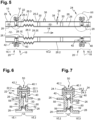
- connection system 24 comprises a first downstream crown 42 (or upstream) connected to the external conduit 26, a second downstream crown 42' (or upstream) connected to the internal conduit 28 as well as a sealed connection 44 connecting the first and second downstream crowns 42, 42' (or upstream).
- first and second downstream crowns 42, 42' are pressed against each other over their entire circumference and kept pressed by connecting elements.
- the sealed connection 44 comprises at least one spacer 44.1 inserted between the first and second downstream rings 42, 42' (or upstream) in order to keep them separated in the longitudinal direction over their entire circumference, connecting elements connecting the first and second downstream rings 42, 42' (or upstream) as well as an annular seal 44.2 inserted between the first and second downstream rings 42, 42' (or upstream).
- the connecting elements of the sealed connection 44 are those of the connection system 24.
- the sealed connection 44 comprises several spacers 44.1 distributed over the circumference of the first and second downstream rings 42, 42' (or upstream). Each spacer 44.1 is in the form of a tube crossed by one of the connecting elements.
- the sealed connection 44 may comprise a spacer 44.1 for each connecting element.
- the annular seal 44.2 has an internal diameter substantially equal to the external diameter of the external conduit 26.
- the sealed connection 44 comprises at least one stop 44.3, integral with one of the first and second downstream rings 42, 42' (or upstream), configured according to the pressure difference between the outside of the external conduit 26 and the intermediate space 32.
- the pressure outside the external conduit 26 being significantly higher than that inside the intermediate space 32, the stop 44.3 is tubular, connected to the first downstream ring 42, positioned in the extension of the external conduit 26 and inside the annular seal 44.2.
- the annular seal 44.2 is a seal with a sigma ⁇ cross section, oriented so that the pressure difference on either side of the annular seal 44.2 reinforces the seal.
- connection system 22, 24 comprises at least one downstream crown 42 connected to at least one of the external and internal conduits 26, 28 of a first section, at least one upstream crown 40 connected to at least external and internal conduits 26, 28 of a second section as well as connecting elements 22.3, 24.3 connecting the upstream and downstream crowns 40, 42.
- the internal conduit 28 comprises a first portion 28.1 which extends from the upstream crown 40 to a first end 28.1E and a second portion 28.2 which extends from the downstream crown 42 to a second end 28.2E, the first and second ends 28.1E, 28.2E being configured to slide one inside the other.
- the first end 28.1E slides in the second end 28.2E which has an enlarged cross-section.
- the internal conduit 28 has at least one annular seal 46 interposed between the first and second ends 28.1E, 28.2E, positioned in the overlap zone of the first and second ends 28.1E, 28.2E.
- the internal conduit 28 comprises at least one stop 48 for holding the annular seal 46 in place between the first and second ends 28.1E, 28.2E, configured as a function of the pressure difference between the inside of the internal conduit 28 and the intermediate space 32.
- the pressure inside the internal conduit 28 being significantly higher than that inside the intermediate space 32, the stop 48 comprises a rim 48.1 connected to the second part 28.2 of the internal conduit 28 and positioned at the second end 28.2E.
- the annular seal 46 is a seal of sigma ⁇ cross section, oriented so that the pressure difference on either side of the annular seal 46 reinforces the seal.
- the internal conduit 28 comprises a part 28.1 which extends from the upstream crown 40 to a first end 28.1E, a second part 28.2 which extends from the downstream crown 42 to a second end 28.2E as well as a bellows 28.3 connecting the first and second parts 28.1, 28.2 and more particularly their first and second ends 28.1E, 28.2E.
- the external conduit 26 may comprise first and second parts 26.1, 26.2 as well as a bellows 26.3 connecting the first and second parts 26.1, 26.2.
- the invention is not limited to these embodiments, at least one of the external and internal conduits of at least one section comprising a system for compensating for expansion phenomena in the longitudinal direction.
- At least one connection system 22, 24 comprises at least one spacer 50 interposed between the upstream and downstream crowns 40, 42 to keep them spaced apart and create a buffer space 52 between the upstream and downstream crowns 40, 42.
- connection system 22, 24 comprises several spacers 50 distributed over the entire circumference of the upstream and downstream rings 40, 42.
- Each spacer 50 is a tube configured to house one of the connection elements 22.3, 24.3.
- the connection system 22, 24 comprises as many spacers 50 as there are connection elements 22.3, 24.3.
- the spacers 50 all have the same length (dimension taken in the longitudinal direction).
- the connection system 22, 24 comprises first and second annular seals 54, 56, interposed between the upstream and downstream rings 40, 42, positioned so as to isolate the buffer space 52 from the inside of the internal conduit 28 and from the outside of the external conduit 26.
- the first annular seal 54 is positioned in the extension of the external conduits 26 and the second annular seal 56 is positioned inside the first annular seal 54, in the extension of the internal conduits 28.
- the first and second annular seals 54, 56 are seals with a sigma ⁇ cross section, oriented so that the pressure difference on either side of the annular seals 54, 56 reinforces the seal.
- the first and second annular seals 54, 56 delimit with the upstream and downstream rings 40, 42 a buffer space 52 which makes it possible to detect a possible leak at the level of the connection system 22, 24.
- the connection system 22, 24 may not include a spacer 50 if the first and second annular seals are configured to ensure the function of spacer 50.
- each connection system 22, 24 comprises at least one spacer 50 for keeping the upstream and downstream rings 40, 42 spaced apart as well as first and second annular seals 54, 56 delimiting with the upstream and downstream rings 40, 42 a buffer space 52 containing an atmosphere.
- connection system 22, 24 comprises at least one stop 58 for keeping the first and second annular seals 54, 56 apart.
- This (or these) stop(s) 58 is (are) configured as a function of the pressure difference between, on the one hand, the buffer space 52 and, on the other hand, the interior of the internal conduit 28 and the exterior of the external conduit 26.
- connection system 22, 24 comprises a stop 58, interposed between the first and second annular seals 54, 56, preventing the latter from coming together.
- the stop 58 is a circular rib secured to the upstream crown 40 which has an external diameter substantially equal to the internal diameter of the first annular seal 54 and an internal diameter substantially equal to the external diameter of the second annular seal 56. The latter could be secured to the downstream crown 42.
- At least one of the stops 58 has a dimension, in a longitudinal direction, less than the length of the spacers 50.
- the pipeline 10 comprises at least one leak detection system configured to determine at least one characteristic of the atmosphere of the buffer space 52.
- the buffer space 52 has a given vacuum level.
- the leak detection system comprises at least one pressure sensor for measuring the pressure in the buffer space 52 in order to detect a leak.
- the buffer space 52 contains an inerting gas at a given pressure.
- the leak detection system of the connection system 22, 24 includes at least one sensor configured to detect a concentration of hydrogen or oxygen in the buffer space 52 to detect a leak.
- connection system 22, 24 comprises at least one orifice 60 passing through the upstream or downstream crown 40, 42 to communicate the buffer space 52 with one of the intermediate spaces 32 of the upstream and downstream sections.
- the buffer space 52 and the intermediate space 32 have the same atmosphere, the same pressure and a single leak detection system 34, such as a pressure sensor 38 for detecting a leak in the intermediate and buffer spaces 32, 52.
- connection system 22, 24 comprises several orifices 60 distributed over the circumference of the upstream or downstream crown 40, 42. Providing several orifices improves the detection of a leak in the buffer space 52 by a leak detection system positioned at the intermediate space 32. These orifices 60 are regularly distributed over the entire circumference of the upstream or downstream crown 40, 42. The orifices 60 are provided on the upstream crown 40 of the downstream section. However, they could be positioned on the downstream crown 42 of the upstream section.
- the stop 58 is integral with a first crown among the upstream and downstream crowns 40, 42 and the orifice(s) is (or are) positioned on a second crown among the upstream and downstream crowns 40, 42 different from the first crown.
Landscapes
- Engineering & Computer Science (AREA)
- General Engineering & Computer Science (AREA)
- Mechanical Engineering (AREA)
- Physics & Mathematics (AREA)
- Aviation & Aerospace Engineering (AREA)
- Fluid Mechanics (AREA)
- General Physics & Mathematics (AREA)
- Architecture (AREA)
- Examining Or Testing Airtightness (AREA)
- Pipeline Systems (AREA)
- Measuring Fluid Pressure (AREA)
Claims (8)
- Rohrleitung mit wenigstens einem ersten und einem zweiten Abschnitt (16.1, 16.2) sowie mit wenigstens einem Verbindungssystem (22, 24), das den ersten und den zweiten Abschnitt (16.1, 16.2) miteinander verbindet, wobei jeder der ersten und zweiten Abschnitte (16.1, 16.2) eine äußere Leitung (26), eine innere Leitung (28), die in der äußeren Leitung (26) angeordnet ist, und einen Zwischenraum (32) aufweist, der sich zwischen der äußeren und der inneren Leitung (26, 28) befindet und eine erste Atmosphäre enthält, wobei die Rohrleitung wenigstens ein Leckdetektionssystem (34) aufweist, das so eingerichtet ist, dass es eine Eigenschaft der ersten Atmosphäre bestimmt, wobei das Verbindungssystem (22, 24) wenigstens einen stromabwärtigen Ring (42) aufweist, der mit wenigstens einer der äußeren und inneren Leitungen (26, 28) des ersten Abschnitts (16.1) verbunden ist, wenigstens einen stromaufwärtigen Ring (40) aufweist, der mit wenigstens einer der äußeren und inneren Leitung (26, 28) des zweiten Abschnitts (16.2) verbunden ist, sowie Verbindungselemente (22.3, 24.3) aufweist, die den stromaufwärtigen und den stromabwärtigen Ring (40, 42) miteinander verbinden, wobei das Verbindungssystem (22, 24) erste und zweite ringförmige Dichtungen (54, 56) aufweist, die zwischen den stromaufwärts und stromabwärts gelegenen Ringen (40, 42) angeordnet und so eingerichtet sind, dass sie mit den stromaufwärts und stromabwärts gelegenen Ringen (40, 42) einen Pufferraum (52) begrenzen, der eine zweite Atmosphäre enthält, wobei die Rohrleitung wenigstens ein Leckdetektionssystem aufweist, das so eingerichtet ist, dass es wenigstens eine Eigenschaft der zweiten Atmosphäre bestimmt, wobei das Verbindungssystem (22, 24) wenigstens einen Anschlag (58) aufweist, um die erste und die zweite Ringdichtung (54, 56) voneinander beabstandet zu halten, und wobei die erste Ringdichtung (54) einen Innendurchmesser aufweist, die zweite ringförmige Dichtung (56) innerhalb der ersten ringförmigen Dichtung (54) angeordnet ist und einen Außendurchmesser aufweist und der Anschlag (58) eine kreisförmige Rippe ist, die fest mit einem ersten Ring aus den stromaufwärts und stromabwärts gelegenen Ringen (40, 42) verbunden ist und einen Außendurchmesser aufweist, der im Wesentlichen gleich dem Innendurchmesser der ersten ringförmigen Dichtung (54) ist, und einen Innendurchmesser aufweist, der im Wesentlichen gleich dem Außendurchmesser der zweiten ringförmigen Dichtung (56) ist, und wobei das Verbindungssystem (22, 24) wenigstens eine Öffnung (60) aufweist, die durch einen vom ersten Ring verschiedenen zweiten Ring aus den stromaufwärts und stromabwärts gelegenenen Ringen (40, 42) verläuft, um den Pufferraum (52) und einen der Zwischenräume (32) des ersten und zweiten Abschnitts (16.1, 16.2) in Verbindung zu bringen.
- Rohrleitung nach Anspruch 1, dadurch gekennzeichnet, dass das Verbindungssystem (22, 24) wenigstens einen Abstandshalter (50) aufweist, der zwischen den stromaufwärts und stromabwärts gelegenen Ringen (40, 42) eingefügt ist, um diese voneinander beabstandet zu halten.
- Rohrleitung nach dem vorhergehenden Anspruch, dadurch gekennzeichnet, dass jeder Abstandshalter ein Rohr ist, das so eingerichtet ist, dass es eines der Verbindungselemente (22.3, 24.3) aufnimmt.
- Rohrleitung nach einem der vorhergehenden Ansprüche, dadurch gekennzeichnet, dass die erste und die zweite Ringdichtung (54, 56) Dichtungen mit Sigma-Querschnitt (Σ) sind.
- Rohrleitungen nach einem der vorhergehenden Ansprüche, dadurch gekennzeichnet, dass das Verbindungssystem (22, 24) für wenigstens einen der ersten und zweiten Abschnitte (16.1, 16.2) einen ersten Ring (42), der mit der äußeren Leitung (26) verbunden ist, einen zweiten Ring (42'), der mit der inneren Leitung (28) verbunden ist, sowie eine dichte Verbindung (44) aufweist, die den ersten und zweiten Ring (42, 42') miteinander verbindet.
- Rohrleitung nach dem vorhergehenden Anspruch, dadurch gekennzeichnet, dass die dichte Verbindung (44) wenigstens einen Abstandshalter (44.1), der zwischen dem ersten und dem zweiten Ring (42, 42') eingefügt ist, um sie auseinanderzuhalten, Verbindungselemente, die den ersten und den zweiten Ring (42, 42') verbinden, sowie eine ringförmige Dichtung (44.2) aufweist, die zwischen dem ersten und dem zweiten Ring (42, 42') eingefügt ist.
- Rohrleitung nach einem der vorhergehenden Ansprüche, dadurch gekennzeichnet, dass wenigstens eine der äußeren und inneren Leitungen (26, 28) von wenigstens einem der ersten und zweiten Abschnitte (16.1, 16.2) ein System zur Kompensation von Dehnungserscheinungen aufweist.
- Luftfahrzeug mit wenigstens einer Rohrleitung nach einem der vorhergehenden Ansprüche.
Applications Claiming Priority (1)
| Application Number | Priority Date | Filing Date | Title |
|---|---|---|---|
| FR2110236A FR3127543A1 (fr) | 2021-09-28 | 2021-09-28 | Canalisation d’hydrogène à double peau comprenant au moins un système de détection de fuite au niveau d’au moins un système de raccordement, aéronef comprenant au moins une telle canalisation |
Publications (2)
| Publication Number | Publication Date |
|---|---|
| EP4155597A1 EP4155597A1 (de) | 2023-03-29 |
| EP4155597B1 true EP4155597B1 (de) | 2024-11-06 |
Family
ID=79270205
Family Applications (1)
| Application Number | Title | Priority Date | Filing Date |
|---|---|---|---|
| EP22194723.7A Active EP4155597B1 (de) | 2021-09-28 | 2022-09-08 | Wasserstoffleitung mit doppelter wand mit mindestens einem system zur erkennung von lecks an mindestens einem verbindungssystem, luftfahrzeug mit mindestens einer solchen leitung |
Country Status (4)
| Country | Link |
|---|---|
| US (1) | US12319429B2 (de) |
| EP (1) | EP4155597B1 (de) |
| CN (1) | CN115875618A (de) |
| FR (1) | FR3127543A1 (de) |
Families Citing this family (10)
| Publication number | Priority date | Publication date | Assignee | Title |
|---|---|---|---|---|
| NL2024894B1 (en) * | 2020-02-13 | 2021-09-15 | Ddc Eng B V | Hose |
| EP4249380B1 (de) * | 2022-03-21 | 2025-07-30 | Zero Emissions Aerospace Limited | Kraftstoffleitungs-sicherheitsschutzsystem |
| EP4455021B1 (de) | 2023-04-26 | 2025-10-29 | Airbus Operations (S.A.S.) | Flugzeug mit mindestens einer wasserstoffversorgungsvorrichtung mit mindestens einem gasabführungssystem im falle eines lecks |
| CN116817050B (zh) * | 2023-06-29 | 2025-11-07 | 河北宾宏石化设备有限公司 | 一种可调节密封绝缘接头 |
| FR3151074B1 (fr) * | 2023-07-12 | 2025-07-18 | Eti Group | Système de transfert de fluide, dispositif joint tournant comportant un tel système, empilement de dispositifs joint tournant et installation d’exploitation de fluides |
| GB2632126B (en) * | 2023-07-24 | 2025-08-27 | Airbus Operations Ltd | Double-wall pipe for an aircraft fuel system |
| US20250100705A1 (en) * | 2023-09-22 | 2025-03-27 | General Electric Company | Methods and apparatus for leak detection and mitigation for hydrogen fueled aircraft |
| FR3159595A1 (fr) * | 2024-02-27 | 2025-08-29 | Safran Aircraft Engines | Système de sécurisation d’un circuit de fluide à risque d’aéronef, procédé de montage et procédé d’utilisation associés |
| FR3160003A1 (fr) * | 2024-03-06 | 2025-09-12 | Airbus Operations | Conduit à triple peau, aéronef comprenant au moins un tel conduit à triple peau |
| US20250305606A1 (en) * | 2024-03-28 | 2025-10-02 | Tai-Yang Research Company | Modular Cryogenic Fluid High Voltage Transfer Line |
Family Cites Families (10)
| Publication number | Priority date | Publication date | Assignee | Title |
|---|---|---|---|---|
| US3068026A (en) * | 1958-06-13 | 1962-12-11 | Gen Motors Corp | Cryogenic fluid transfer line coupling |
| US3797564A (en) * | 1972-04-17 | 1974-03-19 | H Dickinson | Adjustable soft packing seal |
| US4723441A (en) * | 1985-11-07 | 1988-02-09 | Ply-Flow Engineering, Inc. | Piping system for hazardous fluids |
| US5088774A (en) * | 1990-05-07 | 1992-02-18 | Tylan General, Inc. | Coupling for interconnection of coaxial tubing |
| US6848720B2 (en) * | 2002-08-09 | 2005-02-01 | The Boeing Company | Shrouded fluid-conducting apparatus |
| GB0523573D0 (en) * | 2005-11-18 | 2005-12-28 | Airbus Uk Ltd | Aircraft fuel pipe coupling |
| US7942452B2 (en) * | 2007-11-20 | 2011-05-17 | The Boeing Company | Flange fitting with leak sensor port |
| KR101049429B1 (ko) * | 2009-06-18 | 2011-07-15 | 한국수력원자력 주식회사 | 불활성가스를 이용한 누설감지용 이중배관 플랜지 커플러 |
| EP2927471A1 (de) * | 2014-04-04 | 2015-10-07 | Caterpillar Motoren GmbH & Co. KG | Doppelwandiges Kraftstoffversorgungsleitungselement und Anschlussflansch dafür |
| JP7152857B2 (ja) * | 2017-12-28 | 2022-10-13 | 川崎重工業株式会社 | 流体荷役継手および流体荷役装置 |
-
2021
- 2021-09-28 FR FR2110236A patent/FR3127543A1/fr active Pending
-
2022
- 2022-09-08 EP EP22194723.7A patent/EP4155597B1/de active Active
- 2022-09-26 US US17/952,411 patent/US12319429B2/en active Active
- 2022-09-27 CN CN202211183176.6A patent/CN115875618A/zh active Pending
Also Published As
| Publication number | Publication date |
|---|---|
| EP4155597A1 (de) | 2023-03-29 |
| US20230102097A1 (en) | 2023-03-30 |
| CN115875618A (zh) | 2023-03-31 |
| US12319429B2 (en) | 2025-06-03 |
| FR3127543A1 (fr) | 2023-03-31 |
Similar Documents
| Publication | Publication Date | Title |
|---|---|---|
| EP4155597B1 (de) | Wasserstoffleitung mit doppelter wand mit mindestens einem system zur erkennung von lecks an mindestens einem verbindungssystem, luftfahrzeug mit mindestens einer solchen leitung | |
| EP1561991B1 (de) | Schnellkupplungsmuffe und Schnellkupplung mit solcher Schnellkupplungsmuffe | |
| EP0432013B1 (de) | Rohrverbindung mit einer Vorrichtung zur Ableitung von Lecken | |
| FR2883599A1 (fr) | Dispositif de liaison entre une enceinte de passage d'air de refroidissement et un aubage de distributeur dans une turbomachine | |
| EP0207015A2 (de) | Belüfteter Kollektor für ein Gasverteilungsnetz für Haushalt- oder andere Benutzer | |
| EP4215791A1 (de) | Vorrichtung zum verbinden zweier doppelwandleitungen und wasserstoffleitung mit dieser verbindungsvorrichtung | |
| EP3601985B1 (de) | Vorrichtung zur dichtungsprüfung, rohrverbindung und entsprechende verwendung | |
| WO2020225262A1 (fr) | Tête de réservoir pour gaz sous pression | |
| EP4173962A1 (de) | Gehäuse mit inertisierungsgas und mit einem flüssigkeitsausstosssystem, flugzeug mit einem solchen gehäuse | |
| FR2998634A1 (fr) | Vanne a obturateur spherique, notamment pour turbine a gaz | |
| EP2365295B1 (de) | Zähler mit normierter Ultraschall-Messzelle vom Kapseltyp | |
| WO2020038862A1 (fr) | Dispositif de raccordement étanche d'un premier tuyau à un deuxième tuyau | |
| EP1004806B1 (de) | Abgedichtete drehbare Verbindungsvorrichtung die Bewegungen erlaubt | |
| EP1248029A1 (de) | Schnellkupplung für die lösbare Verbindung zweier Rohrleitungen und ihre Verwendung | |
| EP3204679B1 (de) | Kupplung zur kräuselung auf mindestens ein rohr, rohrsatz mit solch einer kupplung und verfahren zur montage eines rohres mit solch einer kupplung | |
| FR3000133A1 (fr) | Ligne d'echappement de vehicule automobile comportant une rotule perfectionnee | |
| EP4455021A1 (de) | Flugzeug mit mindestens einer wasserstoffversorgungsvorrichtung mit mindestens einem gasabführungssystem im falle eines lecks | |
| FR3044158A1 (fr) | Assemblage de penetration electrique de cuve d'un reacteur nucleaire | |
| EP1090245A1 (de) | Anordnungsverfahren zum verbinden einer armatur mit einem rohrelement und ein neuer typ kupplung zur duerchführung des verfahrens | |
| WO2021191529A1 (fr) | Dispositif d'etancheite dynamique pour sonde de turbomachine | |
| EP3685087B1 (de) | Verfahren zur detektion eines lecks in einem verbindungssystem zwischen einem ausgabeelement und einem aufnahmeelement | |
| EP4382433B1 (de) | Luftfahrzeug mit mindestens einer wasserstoffversorgungsvorrichtung mit einem wasserstoffspeicher sowie in mindestens einem speicherfesten behälter und mindestens einem abnehmbaren behälter verteilt angeordneten einrichtungen | |
| FR2961577A1 (fr) | Embout de raccordement d'une conduite flexible de transport d'un fluide cryogenique | |
| FR3153646A3 (fr) | Tourelle à gaz pour pompe à vide | |
| FR3066009A1 (fr) | Canne de prevaporisation pour une turbomachine |
Legal Events
| Date | Code | Title | Description |
|---|---|---|---|
| PUAI | Public reference made under article 153(3) epc to a published international application that has entered the european phase |
Free format text: ORIGINAL CODE: 0009012 |
|
| STAA | Information on the status of an ep patent application or granted ep patent |
Free format text: STATUS: THE APPLICATION HAS BEEN PUBLISHED |
|
| AK | Designated contracting states |
Kind code of ref document: A1 Designated state(s): AL AT BE BG CH CY CZ DE DK EE ES FI FR GB GR HR HU IE IS IT LI LT LU LV MC MK MT NL NO PL PT RO RS SE SI SK SM TR |
|
| STAA | Information on the status of an ep patent application or granted ep patent |
Free format text: STATUS: REQUEST FOR EXAMINATION WAS MADE |
|
| 17P | Request for examination filed |
Effective date: 20230921 |
|
| RBV | Designated contracting states (corrected) |
Designated state(s): AL AT BE BG CH CY CZ DE DK EE ES FI FR GB GR HR HU IE IS IT LI LT LU LV MC MK MT NL NO PL PT RO RS SE SI SK SM TR |
|
| GRAP | Despatch of communication of intention to grant a patent |
Free format text: ORIGINAL CODE: EPIDOSNIGR1 |
|
| STAA | Information on the status of an ep patent application or granted ep patent |
Free format text: STATUS: GRANT OF PATENT IS INTENDED |
|
| RIC1 | Information provided on ipc code assigned before grant |
Ipc: F16L 27/12 20060101ALN20240417BHEP Ipc: F16L 17/073 20060101ALN20240417BHEP Ipc: G01M 3/28 20060101ALI20240417BHEP Ipc: B64D 37/32 20060101ALI20240417BHEP Ipc: B64D 37/30 20060101ALI20240417BHEP Ipc: F16J 15/48 20060101ALI20240417BHEP Ipc: F16J 15/10 20060101ALI20240417BHEP Ipc: F16J 15/08 20060101ALI20240417BHEP Ipc: F16L 51/02 20060101ALI20240417BHEP Ipc: F16L 51/00 20060101ALI20240417BHEP Ipc: F16L 17/06 20060101ALI20240417BHEP Ipc: F16L 17/035 20060101ALI20240417BHEP Ipc: F16L 39/00 20060101AFI20240417BHEP |
|
| INTG | Intention to grant announced |
Effective date: 20240502 |
|
| GRAS | Grant fee paid |
Free format text: ORIGINAL CODE: EPIDOSNIGR3 |
|
| GRAA | (expected) grant |
Free format text: ORIGINAL CODE: 0009210 |
|
| STAA | Information on the status of an ep patent application or granted ep patent |
Free format text: STATUS: THE PATENT HAS BEEN GRANTED |
|
| AK | Designated contracting states |
Kind code of ref document: B1 Designated state(s): AL AT BE BG CH CY CZ DE DK EE ES FI FR GB GR HR HU IE IS IT LI LT LU LV MC MK MT NL NO PL PT RO RS SE SI SK SM TR |
|
| REG | Reference to a national code |
Ref country code: GB Ref legal event code: FG4D Free format text: NOT ENGLISH |
|
| REG | Reference to a national code |
Ref country code: CH Ref legal event code: EP |
|
| REG | Reference to a national code |
Ref country code: DE Ref legal event code: R096 Ref document number: 602022007420 Country of ref document: DE |
|
| REG | Reference to a national code |
Ref country code: IE Ref legal event code: FG4D Free format text: LANGUAGE OF EP DOCUMENT: FRENCH |
|
| REG | Reference to a national code |
Ref country code: LT Ref legal event code: MG9D |
|
| REG | Reference to a national code |
Ref country code: NL Ref legal event code: MP Effective date: 20241106 |
|
| PG25 | Lapsed in a contracting state [announced via postgrant information from national office to epo] |
Ref country code: IS Free format text: LAPSE BECAUSE OF FAILURE TO SUBMIT A TRANSLATION OF THE DESCRIPTION OR TO PAY THE FEE WITHIN THE PRESCRIBED TIME-LIMIT Effective date: 20250306 Ref country code: HR Free format text: LAPSE BECAUSE OF FAILURE TO SUBMIT A TRANSLATION OF THE DESCRIPTION OR TO PAY THE FEE WITHIN THE PRESCRIBED TIME-LIMIT Effective date: 20241106 Ref country code: PT Free format text: LAPSE BECAUSE OF FAILURE TO SUBMIT A TRANSLATION OF THE DESCRIPTION OR TO PAY THE FEE WITHIN THE PRESCRIBED TIME-LIMIT Effective date: 20250306 |
|
| PG25 | Lapsed in a contracting state [announced via postgrant information from national office to epo] |
Ref country code: FI Free format text: LAPSE BECAUSE OF FAILURE TO SUBMIT A TRANSLATION OF THE DESCRIPTION OR TO PAY THE FEE WITHIN THE PRESCRIBED TIME-LIMIT Effective date: 20241106 Ref country code: NL Free format text: LAPSE BECAUSE OF FAILURE TO SUBMIT A TRANSLATION OF THE DESCRIPTION OR TO PAY THE FEE WITHIN THE PRESCRIBED TIME-LIMIT Effective date: 20241106 |
|
| REG | Reference to a national code |
Ref country code: AT Ref legal event code: MK05 Ref document number: 1739674 Country of ref document: AT Kind code of ref document: T Effective date: 20241106 |
|
| PG25 | Lapsed in a contracting state [announced via postgrant information from national office to epo] |
Ref country code: BG Free format text: LAPSE BECAUSE OF FAILURE TO SUBMIT A TRANSLATION OF THE DESCRIPTION OR TO PAY THE FEE WITHIN THE PRESCRIBED TIME-LIMIT Effective date: 20241106 |
|
| PG25 | Lapsed in a contracting state [announced via postgrant information from national office to epo] |
Ref country code: ES Free format text: LAPSE BECAUSE OF FAILURE TO SUBMIT A TRANSLATION OF THE DESCRIPTION OR TO PAY THE FEE WITHIN THE PRESCRIBED TIME-LIMIT Effective date: 20241106 |
|
| PG25 | Lapsed in a contracting state [announced via postgrant information from national office to epo] |
Ref country code: NO Free format text: LAPSE BECAUSE OF FAILURE TO SUBMIT A TRANSLATION OF THE DESCRIPTION OR TO PAY THE FEE WITHIN THE PRESCRIBED TIME-LIMIT Effective date: 20250206 |
|
| PG25 | Lapsed in a contracting state [announced via postgrant information from national office to epo] |
Ref country code: LV Free format text: LAPSE BECAUSE OF FAILURE TO SUBMIT A TRANSLATION OF THE DESCRIPTION OR TO PAY THE FEE WITHIN THE PRESCRIBED TIME-LIMIT Effective date: 20241106 Ref country code: GR Free format text: LAPSE BECAUSE OF FAILURE TO SUBMIT A TRANSLATION OF THE DESCRIPTION OR TO PAY THE FEE WITHIN THE PRESCRIBED TIME-LIMIT Effective date: 20250207 Ref country code: AT Free format text: LAPSE BECAUSE OF FAILURE TO SUBMIT A TRANSLATION OF THE DESCRIPTION OR TO PAY THE FEE WITHIN THE PRESCRIBED TIME-LIMIT Effective date: 20241106 |
|
| PG25 | Lapsed in a contracting state [announced via postgrant information from national office to epo] |
Ref country code: PL Free format text: LAPSE BECAUSE OF FAILURE TO SUBMIT A TRANSLATION OF THE DESCRIPTION OR TO PAY THE FEE WITHIN THE PRESCRIBED TIME-LIMIT Effective date: 20241106 |
|
| PG25 | Lapsed in a contracting state [announced via postgrant information from national office to epo] |
Ref country code: RS Free format text: LAPSE BECAUSE OF FAILURE TO SUBMIT A TRANSLATION OF THE DESCRIPTION OR TO PAY THE FEE WITHIN THE PRESCRIBED TIME-LIMIT Effective date: 20250206 |
|
| PG25 | Lapsed in a contracting state [announced via postgrant information from national office to epo] |
Ref country code: SM Free format text: LAPSE BECAUSE OF FAILURE TO SUBMIT A TRANSLATION OF THE DESCRIPTION OR TO PAY THE FEE WITHIN THE PRESCRIBED TIME-LIMIT Effective date: 20241106 |
|
| PG25 | Lapsed in a contracting state [announced via postgrant information from national office to epo] |
Ref country code: DK Free format text: LAPSE BECAUSE OF FAILURE TO SUBMIT A TRANSLATION OF THE DESCRIPTION OR TO PAY THE FEE WITHIN THE PRESCRIBED TIME-LIMIT Effective date: 20241106 |
|
| PG25 | Lapsed in a contracting state [announced via postgrant information from national office to epo] |
Ref country code: EE Free format text: LAPSE BECAUSE OF FAILURE TO SUBMIT A TRANSLATION OF THE DESCRIPTION OR TO PAY THE FEE WITHIN THE PRESCRIBED TIME-LIMIT Effective date: 20241106 |
|
| PG25 | Lapsed in a contracting state [announced via postgrant information from national office to epo] |
Ref country code: RO Free format text: LAPSE BECAUSE OF FAILURE TO SUBMIT A TRANSLATION OF THE DESCRIPTION OR TO PAY THE FEE WITHIN THE PRESCRIBED TIME-LIMIT Effective date: 20241106 |
|
| PG25 | Lapsed in a contracting state [announced via postgrant information from national office to epo] |
Ref country code: SK Free format text: LAPSE BECAUSE OF FAILURE TO SUBMIT A TRANSLATION OF THE DESCRIPTION OR TO PAY THE FEE WITHIN THE PRESCRIBED TIME-LIMIT Effective date: 20241106 |
|
| PG25 | Lapsed in a contracting state [announced via postgrant information from national office to epo] |
Ref country code: CZ Free format text: LAPSE BECAUSE OF FAILURE TO SUBMIT A TRANSLATION OF THE DESCRIPTION OR TO PAY THE FEE WITHIN THE PRESCRIBED TIME-LIMIT Effective date: 20241106 |
|
| PG25 | Lapsed in a contracting state [announced via postgrant information from national office to epo] |
Ref country code: IT Free format text: LAPSE BECAUSE OF FAILURE TO SUBMIT A TRANSLATION OF THE DESCRIPTION OR TO PAY THE FEE WITHIN THE PRESCRIBED TIME-LIMIT Effective date: 20241106 |
|
| REG | Reference to a national code |
Ref country code: DE Ref legal event code: R097 Ref document number: 602022007420 Country of ref document: DE |
|
| PG25 | Lapsed in a contracting state [announced via postgrant information from national office to epo] |
Ref country code: SE Free format text: LAPSE BECAUSE OF FAILURE TO SUBMIT A TRANSLATION OF THE DESCRIPTION OR TO PAY THE FEE WITHIN THE PRESCRIBED TIME-LIMIT Effective date: 20241106 |
|
| PLBE | No opposition filed within time limit |
Free format text: ORIGINAL CODE: 0009261 |
|
| STAA | Information on the status of an ep patent application or granted ep patent |
Free format text: STATUS: NO OPPOSITION FILED WITHIN TIME LIMIT |
|
| PGFP | Annual fee paid to national office [announced via postgrant information from national office to epo] |
Ref country code: DE Payment date: 20250919 Year of fee payment: 4 |
|
| 26N | No opposition filed |
Effective date: 20250807 |
|
| PGFP | Annual fee paid to national office [announced via postgrant information from national office to epo] |
Ref country code: FR Payment date: 20250922 Year of fee payment: 4 |