EP4382011A1 - Systeme de moulin à café - Google Patents
Systeme de moulin à café Download PDFInfo
- Publication number
- EP4382011A1 EP4382011A1 EP23215393.2A EP23215393A EP4382011A1 EP 4382011 A1 EP4382011 A1 EP 4382011A1 EP 23215393 A EP23215393 A EP 23215393A EP 4382011 A1 EP4382011 A1 EP 4382011A1
- Authority
- EP
- European Patent Office
- Prior art keywords
- coffee grinder
- drive
- drive device
- housing
- coupled
- Prior art date
- Legal status (The legal status is an assumption and is not a legal conclusion. Google has not performed a legal analysis and makes no representation as to the accuracy of the status listed.)
- Pending
Links
- 230000008878 coupling Effects 0.000 claims description 77
- 238000010168 coupling process Methods 0.000 claims description 77
- 238000005859 coupling reaction Methods 0.000 claims description 77
- 238000003780 insertion Methods 0.000 claims description 12
- 230000037431 insertion Effects 0.000 claims description 12
- 238000000034 method Methods 0.000 claims description 12
- 230000008569 process Effects 0.000 claims description 12
- 210000003813 thumb Anatomy 0.000 claims description 8
- 241000533293 Sesbania emerus Species 0.000 claims description 7
- 230000008901 benefit Effects 0.000 description 11
- 229920001971 elastomer Polymers 0.000 description 5
- 239000000806 elastomer Substances 0.000 description 4
- 238000012423 maintenance Methods 0.000 description 2
- 239000000843 powder Substances 0.000 description 2
- 230000008439 repair process Effects 0.000 description 2
- 238000004140 cleaning Methods 0.000 description 1
- 238000010276 construction Methods 0.000 description 1
- 230000000694 effects Effects 0.000 description 1
- 210000003811 finger Anatomy 0.000 description 1
- 230000009931 harmful effect Effects 0.000 description 1
- 230000007257 malfunction Effects 0.000 description 1
- 239000000463 material Substances 0.000 description 1
- 230000007246 mechanism Effects 0.000 description 1
Images

Classifications
-
- A—HUMAN NECESSITIES
- A47—FURNITURE; DOMESTIC ARTICLES OR APPLIANCES; COFFEE MILLS; SPICE MILLS; SUCTION CLEANERS IN GENERAL
- A47J—KITCHEN EQUIPMENT; COFFEE MILLS; SPICE MILLS; APPARATUS FOR MAKING BEVERAGES
- A47J42/00—Coffee mills; Spice mills
- A47J42/38—Parts or details
- A47J42/46—Driving mechanisms; Coupling to drives
-
- A—HUMAN NECESSITIES
- A47—FURNITURE; DOMESTIC ARTICLES OR APPLIANCES; COFFEE MILLS; SPICE MILLS; SUCTION CLEANERS IN GENERAL
- A47J—KITCHEN EQUIPMENT; COFFEE MILLS; SPICE MILLS; APPARATUS FOR MAKING BEVERAGES
- A47J42/00—Coffee mills; Spice mills
- A47J42/02—Coffee mills; Spice mills having grinding cones
- A47J42/04—Coffee mills; Spice mills having grinding cones hand driven
-
- A—HUMAN NECESSITIES
- A47—FURNITURE; DOMESTIC ARTICLES OR APPLIANCES; COFFEE MILLS; SPICE MILLS; SUCTION CLEANERS IN GENERAL
- A47J—KITCHEN EQUIPMENT; COFFEE MILLS; SPICE MILLS; APPARATUS FOR MAKING BEVERAGES
- A47J42/00—Coffee mills; Spice mills
- A47J42/02—Coffee mills; Spice mills having grinding cones
- A47J42/06—Coffee mills; Spice mills having grinding cones mechanically driven
-
- A—HUMAN NECESSITIES
- A47—FURNITURE; DOMESTIC ARTICLES OR APPLIANCES; COFFEE MILLS; SPICE MILLS; SUCTION CLEANERS IN GENERAL
- A47J—KITCHEN EQUIPMENT; COFFEE MILLS; SPICE MILLS; APPARATUS FOR MAKING BEVERAGES
- A47J42/00—Coffee mills; Spice mills
- A47J42/32—Coffee mills; Spice mills with other grinding or pulverising members
- A47J42/34—Coffee mills; Spice mills with other grinding or pulverising members hand driven
-
- A—HUMAN NECESSITIES
- A47—FURNITURE; DOMESTIC ARTICLES OR APPLIANCES; COFFEE MILLS; SPICE MILLS; SUCTION CLEANERS IN GENERAL
- A47J—KITCHEN EQUIPMENT; COFFEE MILLS; SPICE MILLS; APPARATUS FOR MAKING BEVERAGES
- A47J42/00—Coffee mills; Spice mills
- A47J42/32—Coffee mills; Spice mills with other grinding or pulverising members
- A47J42/36—Coffee mills; Spice mills with other grinding or pulverising members mechanically driven
Definitions
- the invention relates to a coffee grinder system with a coffee grinder which includes a housing and a grinder arranged in the housing, and with a drive device for driving the grinder.
- Coffee grinder systems of the type mentioned above are usually designed in such a way that the housing contains the drive device in the form of an electric drive motor.
- the drive device is installed in the housing at the factory and is precisely adjusted in a complex manner relative to the grinder, which is also installed in the housing. If the adjustment is not completely correct, this will lead to a reduced service life, malfunctions such as sudden jamming, and/or damage. Since simple disassembly into components for maintenance and repair purposes is usually not provided for and usually not possible with such coffee grinder systems, a repair is generally not worthwhile if the problems mentioned above occur.
- a coffee grinder system of the type mentioned at the outset which is characterized in that the coffee grinder can be or is coupled to the drive device in a movable and/or self-centering manner.
- the coffee grinder system according to the invention has the very special advantage that forces that could cause increased wear of components of the coffee grinder system and/or jamming of the connection between the drive device and the coffee grinder cannot take effect, in particular because the movable connection allows the relevant components to move relative to one another and/or such forces do not occur at all due to the self-centering.
- the drive device can advantageously have an electric drive motor.
- the drive device can have at least one gear that is connected downstream of the electric drive motor.
- the drive motor and the gear can in particular be arranged coaxially to one another.
- the drive device has a manually operable operating element, such as a crank or an operating lever pivoted back and forth, wherein at least one gear can be connected downstream of the manually operable operating element.
- a manually operable operating element such as a crank or an operating lever pivoted back and forth, wherein at least one gear can be connected downstream of the manually operable operating element.
- the coffee grinder has a rotatably mounted drive element for introducing a torque into the grinder.
- the drive device has an output element, in particular one that is rotatably mounted about an output rotation axis and/or driven to rotate, which is or can be connected to the drive element in a torque-transmitting manner.
- the drive element in particular a drive shaft of the drive element, is connected in a rotationally fixed manner to a grinding rotor, in particular a grinding cone of the grinder.
- a grinding stator of the grinder for example a grinding ring, can be arranged in a rotationally fixed manner relative to the housing.
- the coffee grinder coupled to the drive device is movable in a plane perpendicular to the drive rotation axis and/or in a plane perpendicular to the output rotation axis.
- the coffee grinder coupled to the drive device can be linearly movable in a direction perpendicular to the drive rotation axis and/or in a direction perpendicular to the drive rotation axis.
- it can advantageously be provided that the coffee grinder coupled to the drive device is immobile in the direction of the drive rotation axis.
- the coupling device by means of which the housing of the coffee grinder can be coupled to the drive device, is designed such that it allows a movement of the coffee grinder coupled to the drive device in a plane perpendicular to the drive rotation axis and/or in a plane perpendicular to the output rotation axis.
- the coupling device can be designed such that it allows a linear movement of the coffee grinder coupled to the drive device in a direction perpendicular to the drive rotation axis and/or in a direction perpendicular to the output rotation axis.
- the coupling device by means of which the housing of the coffee grinder can be coupled to the drive device can be designed in such a way that it does not prevent any movement of the drive device in the direction of the drive rotation axis and/or in the direction of the output rotation axis. It has been recognized that increased wear of components of the coffee grinder system and/or jamming of the connection between the drive device and the coffee grinder can be avoided even if no movement of the coffee grinder coupled to the drive device in the direction of the drive rotation axis and/or in the direction of the output rotation axis is possible. Nevertheless, the provision of such mobility is not fundamentally excluded.
- the coffee grinder coupled to the drive device can be pivoted about a pivot axis that is not parallel and not coaxial to the drive rotation axis and/or about a pivot axis that is not parallel and not coaxial to the output rotation axis.
- the coffee grinder coupled to the drive device can be pivoted about a pivot axis that is perpendicular to the drive rotation axis and/or about a pivot axis that is perpendicular to the output rotation axis.
- the coupling device by means of which the housing of the coffee grinder can be coupled to the drive device, is designed in such a way that it allows a pivoting movement of the coffee grinder coupled to the drive device about a pivot axis that is not parallel and not coaxial to the drive rotation axis and/or about a pivot axis that is not parallel and not coaxial to the output rotation axis.
- the coupling device can be designed in such a way that it allows a pivoting movement of the coffee grinder coupled to the drive device about a pivot axis that is perpendicular to the drive rotation axis and/or about a pivot axis that is perpendicular to the output rotation axis. swivel axis.
- the coffee grinder coupled to the drive device can be coupled or is coupled to the drive device in a self-centering manner in relation to a direction different from the direction of the drive rotation axis and/or in relation to a direction different from the direction of the output rotation axis.
- the coffee grinder can be coupled or is coupled to the drive device in a self-centering manner in relation to a direction perpendicular to the direction of the drive rotation axis and/or in relation to a direction perpendicular to the direction of the output rotation axis.
- the coupling device by means of which the housing of the coffee grinder can be coupled to the drive device, is designed in such a way that it allows self-centering of the coffee grinder coupled to the drive device in a direction different from the direction of the drive rotation axis and/or in a direction different from the direction of the output rotation axis.
- the coupling device can be designed in such a way that it allows self-centering of the coffee grinder coupled to the drive device in a direction perpendicular to the direction of the drive rotation axis and/or in a direction perpendicular to the direction of the output rotation axis.
- the torque-transmitting connection is designed in such a way that it can be made by the user without tools. Alternatively or additionally, it can advantageously be provided that the torque-transmitting connection can be released again without tools.
- These designs have the very special advantage that the coffee grinder system can be easily disassembled and reassembled by the user, for example for cleaning or maintenance purposes.
- these designs have the very special advantage that the drive device can be easily uncoupled in order to be able to connect another, in particular different, drive device or a hand crank instead.
- a design in which the torque-transmitting connection is designed as a compensating coupling or has a compensating coupling is particularly robust and not susceptible to damage.
- the compensating coupling can, for example, be designed in such a way that an offset, in particular an axial offset, of the drive element and the output element, in particular a drive shaft of the drive element and an output shaft of the output element, is compensated.
- the compensating coupling can, for example, be designed according to the principle of an Oldham coupling.
- the compensating coupling it is also possible for the compensating coupling to be designed to compensate for an angular error of the drive element relative to the output element, in particular an angular error of a drive shaft of the drive element relative to an output shaft of the output element.
- the compensating coupling can, for example, be designed according to the principle of a universal joint.
- the compensating coupling can be formed by the drive element and the output element. It is also possible for the compensating coupling to contain the drive element and/or the output element.
- the drive element can have a driver bar arranged transversely to a drive shaft.
- the driver bar can be arranged perpendicular to the axis of rotation of the drive shaft.
- the driver bar has the function of interacting with at least one component of the output element in order to transmit a torque.
- the output element can have, for example, a fork with tines, in particular aligned in the direction of the axis of rotation of the drive element and/or in the direction of the axis of rotation of the output element.
- the tines can rest directly on the driver bar in order to transmit a torque from the output element to the drive element.
- Such a design of the coffee bean system has the very special advantage that the coffee grinder automatically centers itself relative to the drive device during the drive process, in particular when the housing is movably held on the drive device, in particular on a stand of the drive device.
- the driver bar can, for example, run through a through hole in the drive shaft.
- at least one fastening element in particular a clamping screw, can advantageously be present, by means of which the driver bar can be fixed relative to the drive shaft.
- the housing is secured by means of a Coupling device movably coupled or coupled to the drive device.
- the drive element and the output element are designed and arranged in such a way that the torque-transmitting connection is automatically established when the housing is attached to the drive device by means of the coupling device.
- the coupling device has a first coupling element of the drive device and a second coupling element that is arranged on the housing, wherein the coupling elements, the drive element and the output element are designed and positioned in such a way that the drive element and the output element automatically and preferably inevitably come into operative connection with one another when an operative connection is established between the first coupling element and the second coupling element.
- Such an embodiment has the very special advantage that the user can easily couple the coffee grinder to the drive device without having to create several coupling connections in a complex manner.
- the coupling device is preferably designed and arranged to support a torque introduced into the grinder via the drive element.
- the coupling device prevents the housing from rotating when a torque is introduced into the drive element via the output element.
- the coupling device is designed in such a way that movements of the housing, in particular those movements that are required for a centering process, in particular a self-centering process, are possible.
- the coupling device is designed to permit a pivoting movement, in particular a pivoting movement about an axis perpendicular to the axis of rotation of the drive shaft, and/or a linear movement, in particular a linear movement in a plane perpendicular to the axis of rotation of the drive shaft, during a drive process.
- a pivoting movement in particular a pivoting movement about an axis perpendicular to the axis of rotation of the drive shaft
- a linear movement in particular a linear movement in a plane perpendicular to the axis of rotation of the drive shaft
- the coupling device can, for example, have two coupling elements, one of which is part of the drive device and the other of which is arranged on the housing and which can be operatively connected to one another in order to couple the housing to the drive device in a rotationally fixed manner.
- one of the coupling elements can, for example, be designed as a plug pin, while the other of the coupling elements is designed as a plug pin receptacle.
- the coupling element arranged on the housing can be arranged in such a way that it can function as a torque support when the coffee grinder is driven with a hand crank instead of the drive device.
- the coupling element arranged on the housing can be positioned in such a way that it rests on the thumb, in particular on the tip of the thumb, of the user's hand, which completely or partially grasps the preferably circular-cylindrical housing. In this way, the user can support the torque that acts on the housing when the hand crank is operated simply by means of his thumb, in particular in a form-fitting manner, while being able to hold the housing relatively loosely.
- the coupling element arranged on the housing preferably functions as a stop element and the thumb as a counter-stop element.
- the coupling device has a plug pin arranged on the housing, which can be inserted along an insertion direction into a plug pin receptacle of the drive device.
- the drive device has a plug pin that can be inserted along an insertion direction into a plug pin receptacle arranged on the housing.
- the coupling element arranged on the housing can in particular be manufactured in one piece with the housing.
- the coupling element arranged on the housing can be firmly connected to the housing by means of a material connection.
- the coupling element it is also possible for the coupling element to be fastened to the housing in a form-fitting and/or friction-fitting manner, for example by means of at least one screw connection.
- the coupling element is attached to the housing by means of at least one clamp which surrounds the housing.
- a fastening device for fastening the coupling element to the housing can advantageously be provided.
- the fastening device can in particular be designed such that the coupling element can be fastened to the housing without damaging the housing.
- the fastening device can advantageously be designed such that it is possible to retrofit existing coffee grinders that do not have a coupling device for coupling to a drive device.
- the fastening device can advantageously have at least one clamp that surrounds the housing.
- such a coupling device can be designed in such a way that the housing in the coupled state can be pivoted relative to the drive device about the central axis of the plug pin running in the insertion direction and/or that the housing in the coupled state can be displaced relative to the drive device along the central axis of the plug pin running in the insertion direction.
- Such an embodiment is an example of how the coupling device can be designed to enable movements of the housing, in particular those movements that are required for a centering process, in particular a self-centering process.
- the coffee grinder system has a hand crank.
- the coffee grinder is designed to be coupled either to the drive device or to the hand crank.
- the user has the choice of operating the coffee grinder either with the hand crank or coupling the coffee grinder to the, preferably electric, drive device.
- the Users have the option of taking the coffee grinder with them and the hand crank when travelling and using it, while using the coffee grinder at home in combination with the drive device.
- a particularly advantageous design is one in which the coffee grinder can be coupled to the hand crank without tools and/or can be detachably coupled again without tools.
- Plug and clamp connections can be provided for this purpose.
- the hand crank is designed to be inserted into the through hole of the drive shaft instead of the driver bar.
- the hand crank has the same cross section, in particular the same diameter, as the driver bar, at least in the end region.
- the hand crank can be fixed relative to the drive shaft by means of a clamping screw, in particular one that is screwed in axially.
- the housing can advantageously be tubular. Such a design has the particular advantage that it is particularly compact and stable.
- a filling opening can be formed, for example, by an upper tube opening.
- the housing can be cylindrical, in particular circular-cylindrical, at least in sections.
- the housing has a circular outer contour and/or a circular inner contour in a cross-sectional plane perpendicular to its longitudinal extension direction.
- the housing can contain a drive shaft that extends in the longitudinal direction of the, in particular tubular, housing.
- the housing can have at least one bearing block, by means of which at least one mill element, in particular the drive element or at least the drive shaft of the drive element or a component of the grinding mechanism, such as a grinding cone, is mounted so as to be rotatable relative to the housing.
- the housing has a filling opening for coffee beans to be ground and a dispensing opening for the coffee powder.
- the dispensing opening can be formed, for example, by a lower tube opening if the housing is tubular.
- the housing surrounds a receiving space for coffee beans to be ground.
- This type of design has the very special advantage that a supply of coffee beans to be ground can be filled in and, if necessary, can remain in the receiving space for a longer period of time.
- this type of design has the very special advantage that essentially no additional components are required to form the receiving space.
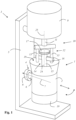
- Fig.1 shows an embodiment of a coffee grinder system according to the invention in a perspective view.
- the coffee grinder system has a coffee grinder 1 which includes a housing 2 and a grinder (not shown) arranged in the housing 2.
- the coffee grinder system also has a drive device 3 for driving the grinder.
- the coffee grinder 1 is coupled to the drive device 3 in a movable and self-centering manner.
- the housing 2 is movably coupled to a stand 5 of the drive device 3 by means of a coupling device 4.
- the coupling device 4 has two coupling elements, one of which is designed, for example, as a plug pin 6, while the other of the coupling elements is designed as a plug pin receptacle 8.
- the coupling device 4 has a plug pin 6 arranged on the housing 2, which is inserted along an insertion direction 7 into a plug pin receptacle 8 of the drive device 3.
- the coffee grinder system allows a particularly simple coupling of the housing 2 to the drive device 3 by inserting the plug pin 6 into the plug pin receptacle 8.
- the coffee grinder 1 is in the In the coupled state shown, it is pivotable relative to the drive device 3 about the central axis of the plug pin 6 running in the insertion direction 7 and is held displaceable relative to the drive device 3 along the central axis of the plug pin 6 running in the insertion direction 7.
- the drive device 3 has an electric drive unit 9 with an electric drive motor (not shown).
- the electric drive unit 9 is firmly connected to the stand 5.
- the electric drive unit 9 can have at least one gear connected downstream of the electric drive motor.
- the electric drive unit 9 has an output element 10.
- the output element 10 includes an output shaft 11 and a fork 12 connected in a rotationally fixed manner to the output shaft 11 with tines 13 aligned in the direction of the output rotation axis 25 of the output element 10.
- the coffee grinder 1 has a drive element 14 which includes a drive shaft 15.
- the drive shaft 15 of the drive element 14 is connected in a rotationally fixed manner to a grinding rotor (not shown) of the grinder (not shown).
- the drive element 14 has a driver bar 16 which is arranged transversely to the drive shaft 15 and is arranged perpendicular to the drive rotation axis 24 of the drive shaft 15.
- the driver bar 16 runs through a through hole in the drive shaft 15 and is fixed relative to the drive shaft with an axially arranged clamping screw 17 which is screwed into an axial threaded hole in the drive shaft 15 on the front side.
- the clamping screw 17 is arranged spatially between the tines 13.
- the driver beam 16 has the function of interacting with the output element 10 to transmit a torque.
- the tines 13 lie directly on the driver beam 16 in order to To transmit torque from the output element 10 to the drive element 14.
- the drive element 14 of the coffee grinder 1 and the output element 10 of the drive device 3 are designed and arranged such that the torque-transmitting connection between them is automatically established when the housing 2 is movably attached to the drive device 3 by means of the coupling device 4.
- the housing 2 is essentially tubular, with a filling opening 18 for the coffee beans to be ground being formed at the upper end.
- the housing 2 is coupled at the lower end to a collecting container 19 for the coffee powder that can be removed without tools.
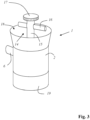
- FIG 2 shows the drive device 3 of the embodiment of a coffee grinder system according to the invention with the coffee grinder 1 removed, while the Figure 3 showing the removed coffee grinder 1.
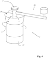
- FIG 4 shows the coffee grinder 1 of the embodiment, to which a hand crank 20 is coupled.
- the clamping screw 17 is first loosened in order to be able to pull the driver bar 16 out of the through hole of the drive shaft 15.
- a coupling end of the hand crank 20 is inserted into the through hole of the drive shaft 15 and fixed by means of the clamping screw 17.
- the coffee grinder 1 can be operated manually using the hand crank 20 instead of the drive device 3, by the user holding the housing 2 in one hand while operating the hand crank 20 with his other hand.
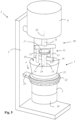
- FIG. 5 shows another embodiment of a coffee grinder system according to the invention in a perspective view.
- the Coffee grinder system differs from that in the Figures 1 and 2
- the coffee grinder system shown in FIG. 1 is characterized in that the coupling device 4 has a rigid retaining ring 22 in which an elastomer ring 21, which can be a rubber ring, for example, is fastened.
- the elastomer ring 21 surrounds the housing 2 of the coffee grinder 1.
- the retaining ring 22 is fastened to the stand 5 by means of a bayonet connection 23.
- the bayonet connection 23 is preferably designed in such a way that the coffee grinder 1 can be detached from the stand 5 and secured to the stand 5 without tools.
- the coffee grinder 1 is coupled to the drive device in a movable and/or self-centering manner.
- the coupling device 4 can be designed in such a way that no movement of the coffee grinder 1 coupled to the drive device 3 in the direction of the drive rotation axis 25 and/or in the direction of the output rotation axis 24 is possible.
- stops (not shown) can be present on the housing 2 for this purpose, which are supported on the retaining ring 22 and thus prevent such a movement.
Landscapes
- Engineering & Computer Science (AREA)
- Mechanical Engineering (AREA)
- Food Science & Technology (AREA)
- Apparatus For Making Beverages (AREA)
Applications Claiming Priority (1)
| Application Number | Priority Date | Filing Date | Title |
|---|---|---|---|
| LU503169A LU503169B1 (de) | 2022-12-09 | 2022-12-09 | Kaffeemühlensystem |
Publications (1)
| Publication Number | Publication Date |
|---|---|
| EP4382011A1 true EP4382011A1 (fr) | 2024-06-12 |
Family
ID=85227383
Family Applications (1)
| Application Number | Title | Priority Date | Filing Date |
|---|---|---|---|
| EP23215393.2A Pending EP4382011A1 (fr) | 2022-12-09 | 2023-12-08 | Systeme de moulin à café |
Country Status (3)
| Country | Link |
|---|---|
| US (1) | US20240225360A1 (fr) |
| EP (1) | EP4382011A1 (fr) |
| LU (1) | LU503169B1 (fr) |
Citations (3)
| Publication number | Priority date | Publication date | Assignee | Title |
|---|---|---|---|---|
| US20170258272A1 (en) * | 2016-03-09 | 2017-09-14 | Chung-Jen Pai | Grinder |
| WO2018021604A1 (fr) * | 2016-07-29 | 2018-02-01 | 이진수 | Mixeur manuel |
| US11432677B2 (en) * | 2018-08-14 | 2022-09-06 | Misaine Trade, Inc. | Modular coffee grinder system |
-
2022
- 2022-12-09 LU LU503169A patent/LU503169B1/de active IP Right Grant
-
2023
- 2023-12-07 US US18/531,791 patent/US20240225360A1/en active Pending
- 2023-12-08 EP EP23215393.2A patent/EP4382011A1/fr active Pending
Patent Citations (3)
| Publication number | Priority date | Publication date | Assignee | Title |
|---|---|---|---|---|
| US20170258272A1 (en) * | 2016-03-09 | 2017-09-14 | Chung-Jen Pai | Grinder |
| WO2018021604A1 (fr) * | 2016-07-29 | 2018-02-01 | 이진수 | Mixeur manuel |
| US11432677B2 (en) * | 2018-08-14 | 2022-09-06 | Misaine Trade, Inc. | Modular coffee grinder system |
Also Published As
| Publication number | Publication date |
|---|---|
| US20240225360A1 (en) | 2024-07-11 |
| LU503169B1 (de) | 2024-06-10 |
Similar Documents
| Publication | Publication Date | Title |
|---|---|---|
| DE69516057T2 (de) | Gelenkiger Arm zur Halterung von Werkzeugen | |
| EP0491149B1 (fr) | Mandrin notamment pour perceuse chirurgicale | |
| EP1889578B1 (fr) | Instrument médical à tige cylindrique | |
| EP2241416A1 (fr) | Robot doté d'une cinématique delta | |
| DE102014206657B4 (de) | Vorrichtung zum Einstellen eines Kameraobjektivs | |
| EP0013714B1 (fr) | Agencement pour un instrument à main dentaire en deux parties pouvant être connectées axialement | |
| DE10109956B4 (de) | Handwerkzeugmaschine mit einem Vorsatzgerät | |
| EP4382011A1 (fr) | Systeme de moulin à café | |
| DE102022132876A1 (de) | Kaffeemühlensystem | |
| EP3185742A1 (fr) | Buse d'aspiration et appareil d'aspiration de surfaces dures | |
| LU506140B1 (de) | Mühle | |
| WO2021122808A1 (fr) | Entraînement linéaire avec moteur électrique pouvant être installé facilement | |
| DE19819251B4 (de) | Handnietgerät zum Setzen von Blindnietmuttern | |
| EP1362559B1 (fr) | Pièce à main à moteur | |
| DE3545705A1 (de) | Handstueck fuer drehantreibbare werkzeuge | |
| DE1260098B (de) | Fernhandhabe | |
| DE102005061254B4 (de) | Fahrzeugsitz | |
| DE1942341B2 (de) | Transportables Rohrreinigungsgerät | |
| DE3616731C2 (fr) | ||
| DE102024101207A1 (de) | Mühle | |
| DE10015186A1 (de) | Objektivfassung | |
| EP1731265B1 (fr) | Dispositif d'alimentation pour outils motorisés d'enfoncement d'éléments de fixation | |
| DE2023573B2 (de) | Vorrichtung zum axialverstellen eines ruehrgeraeterohres | |
| EP3595608B1 (fr) | Bras de support médical avec pivot verrouillable | |
| AT403640B (de) | Schnellkupplung zum anbau eines arbeitsgerätes an einem schlepper |
Legal Events
| Date | Code | Title | Description |
|---|---|---|---|
| PUAI | Public reference made under article 153(3) epc to a published international application that has entered the european phase |
Free format text: ORIGINAL CODE: 0009012 |
|
| STAA | Information on the status of an ep patent application or granted ep patent |
Free format text: STATUS: THE APPLICATION HAS BEEN PUBLISHED |
|
| AK | Designated contracting states |
Kind code of ref document: A1 Designated state(s): AL AT BE BG CH CY CZ DE DK EE ES FI FR GB GR HR HU IE IS IT LI LT LU LV MC ME MK MT NL NO PL PT RO RS SE SI SK SM TR |
|
| STAA | Information on the status of an ep patent application or granted ep patent |
Free format text: STATUS: REQUEST FOR EXAMINATION WAS MADE |
|
| 17P | Request for examination filed |
Effective date: 20241212 |