EP4382007A1 - Neue vorrichtung zur herstellung von kohlensäurehaltigem wasser - Google Patents
Neue vorrichtung zur herstellung von kohlensäurehaltigem wasser Download PDFInfo
- Publication number
- EP4382007A1 EP4382007A1 EP22946483.9A EP22946483A EP4382007A1 EP 4382007 A1 EP4382007 A1 EP 4382007A1 EP 22946483 A EP22946483 A EP 22946483A EP 4382007 A1 EP4382007 A1 EP 4382007A1
- Authority
- EP
- European Patent Office
- Prior art keywords
- gas
- cavity
- rod
- gas vent
- lock
- Prior art date
- Legal status (The legal status is an assumption and is not a legal conclusion. Google has not performed a legal analysis and makes no representation as to the accuracy of the status listed.)
- Pending
Links
Images


Classifications
-
- A—HUMAN NECESSITIES
- A47—FURNITURE; DOMESTIC ARTICLES OR APPLIANCES; COFFEE MILLS; SPICE MILLS; SUCTION CLEANERS IN GENERAL
- A47J—KITCHEN EQUIPMENT; COFFEE MILLS; SPICE MILLS; APPARATUS FOR MAKING BEVERAGES
- A47J31/00—Apparatus for making beverages
- A47J31/40—Beverage-making apparatus with dispensing means for adding a measured quantity of ingredients, e.g. coffee, water, sugar, cocoa, milk, tea
-
- A—HUMAN NECESSITIES
- A23—FOODS OR FOODSTUFFS; TREATMENT THEREOF, NOT COVERED BY OTHER CLASSES
- A23L—FOODS, FOODSTUFFS OR NON-ALCOHOLIC BEVERAGES, NOT OTHERWISE PROVIDED FOR; PREPARATION OR TREATMENT THEREOF
- A23L2/00—Non-alcoholic beverages; Dry compositions or concentrates therefor; Preparation or treatment thereof
- A23L2/52—Adding ingredients
- A23L2/54—Mixing with gases
-
- A—HUMAN NECESSITIES
- A47—FURNITURE; DOMESTIC ARTICLES OR APPLIANCES; COFFEE MILLS; SPICE MILLS; SUCTION CLEANERS IN GENERAL
- A47J—KITCHEN EQUIPMENT; COFFEE MILLS; SPICE MILLS; APPARATUS FOR MAKING BEVERAGES
- A47J31/00—Apparatus for making beverages
- A47J31/44—Parts or details or accessories of beverage-making apparatus
- A47J31/4403—Constructional details
-
- A—HUMAN NECESSITIES
- A47—FURNITURE; DOMESTIC ARTICLES OR APPLIANCES; COFFEE MILLS; SPICE MILLS; SUCTION CLEANERS IN GENERAL
- A47J—KITCHEN EQUIPMENT; COFFEE MILLS; SPICE MILLS; APPARATUS FOR MAKING BEVERAGES
- A47J31/00—Apparatus for making beverages
- A47J31/44—Parts or details or accessories of beverage-making apparatus
- A47J31/58—Safety devices
-
- B—PERFORMING OPERATIONS; TRANSPORTING
- B01—PHYSICAL OR CHEMICAL PROCESSES OR APPARATUS IN GENERAL
- B01F—MIXING, e.g. DISSOLVING, EMULSIFYING OR DISPERSING
- B01F23/00—Mixing according to the phases to be mixed, e.g. dispersing or emulsifying
- B01F23/20—Mixing gases with liquids
- B01F23/23—Mixing gases with liquids by introducing gases into liquid media, e.g. for producing aerated liquids
- B01F23/236—Mixing gases with liquids by introducing gases into liquid media, e.g. for producing aerated liquids specially adapted for aerating or carbonating beverages
- B01F23/2361—Mixing gases with liquids by introducing gases into liquid media, e.g. for producing aerated liquids specially adapted for aerating or carbonating beverages within small containers, e.g. within bottles
-
- B—PERFORMING OPERATIONS; TRANSPORTING
- B01—PHYSICAL OR CHEMICAL PROCESSES OR APPARATUS IN GENERAL
- B01F—MIXING, e.g. DISSOLVING, EMULSIFYING OR DISPERSING
- B01F23/00—Mixing according to the phases to be mixed, e.g. dispersing or emulsifying
- B01F23/20—Mixing gases with liquids
- B01F23/23—Mixing gases with liquids by introducing gases into liquid media, e.g. for producing aerated liquids
- B01F23/236—Mixing gases with liquids by introducing gases into liquid media, e.g. for producing aerated liquids specially adapted for aerating or carbonating beverages
- B01F23/2364—Mixing gases with liquids by introducing gases into liquid media, e.g. for producing aerated liquids specially adapted for aerating or carbonating beverages using security elements, e.g. valves, for relieving overpressure
-
- Y—GENERAL TAGGING OF NEW TECHNOLOGICAL DEVELOPMENTS; GENERAL TAGGING OF CROSS-SECTIONAL TECHNOLOGIES SPANNING OVER SEVERAL SECTIONS OF THE IPC; TECHNICAL SUBJECTS COVERED BY FORMER USPC CROSS-REFERENCE ART COLLECTIONS [XRACs] AND DIGESTS
- Y02—TECHNOLOGIES OR APPLICATIONS FOR MITIGATION OR ADAPTATION AGAINST CLIMATE CHANGE
- Y02W—CLIMATE CHANGE MITIGATION TECHNOLOGIES RELATED TO WASTEWATER TREATMENT OR WASTE MANAGEMENT
- Y02W10/00—Technologies for wastewater treatment
- Y02W10/10—Biological treatment of water, waste water, or sewage
Definitions
- the invention relates to the field of soda, and in particular to a new soda machine.
- a soda machine is a device for preparing soda.
- the present soda machine has a single function, and a soda bottle and a carbon dioxide gas cylinder need to be mounted on the soda machine from the bottom of a connection port at a specified angle, resulting in a small space for a gripper and mounting inconvenience.
- the soda bottle is completely in communication with the external environment, which leads to a certain risk. That is, if the gas pressure in the soda bottle is too high, the bottle body may easily collapse or explode, or the carbon dioxide gas may be directly sprayed to human body and accordingly harm a user, so the safety factor is low; moreover, two independent buttons are required to control gas inletting and gas venting, which leads to a complicated structure.
- the present invention aims to provide a soda machine that is conveniently mounted with a carbon dioxide gas cylinder and a soda bottle, is safer and can control gas inlet and gas vent at the same time by a pressing surface cover.
- the technical solution adopted by the present invention to solve the problems is a new soda machine, comprising:
- a gas vent holder located at the rear end of the gas path body and facing the gas vent hole is provided in the mounting cavity, and the gas vent holder is pivoted on the body mounting support so as to swing transversely relative to the gas path body; a first resetting member is provided on the gas vent holder, and a normal-state abutting position and a reciprocating settling groove located below the normal-state abutting position and smoothly transitioning from the normal-state abutting position are provided on the surface of the gas vent holder; a lower position is provided in the reciprocating settling groove; the gas vent valve comprises a gas vent valve body, a gas vent valve head located at the front end of the gas vent valve body and used for blocking the gas vent passage, and a gas vent valve rod located at the rear end of the gas vent valve body and penetrating the gas vent hole to extend to the outer side of the gas path body; the gas vent valve rod is abutted against the normal-state abutting position under a normal
- the reciprocating settling groove comprises a first slide and a second slide located at an end of the first slide and in communication with the first slide; the front end of the first slide is lower than the surface of the gas vent holder to form a first non-return surface, and an end of the first slide is higher than a starting end of the second slide to form a second non-return surface; and an end of the second slide is smoothly guided to the normal-state abutting position.
- a protective door track located in the body is provided at an upper end of the opening/closing door; the opening/closing door moves transversely relative to the body to open/close the soda cavity; the protective door track is provided with a limit groove hole; a gas pressure lock is provided in the mounting cavity and the gas pressure lock comprises a lock cavity and a lock body located in the lock cavity; a gas-guiding passage extending to the intercommunication area is provided at the front end of the lock cavity, and a gas outlet hole is provided at the rear end of the lock cavity; a front lock head is provided at the front end of the lock body, and a rear lock head used for closing the gas outlet hole is provided at the rear end of the lock body; a lock rod inserted in the gas vent hole and extending to an outer side of the gas pressure lock is provided at the middle portion of the rear end of the lock body; a second resetting member connected to the lock body and driving the lock body to move toward the front end of the lock cavity is provided in the lock cavity
- a limit part is provided on the gas inlet pressure rod, and a gas-filling limit block is pivoted in the mounting cavity;
- the gas-filling limit block comprises a driving end at the front end and a limit end at the rear end, and the limit end movably accesses below the limit part under the swinging action of the driving end;
- the driving end is located on the movement path of the protective door track and partially overlaps with the protective door track in a height direction;
- the protective door track is abutted against the driving end and lifts up the driving end during movement; and a third resetting member driving the driving end to reset downward is provided on the gas-filling limit block.
- a lock notch is provided on the protective door track
- a mechanical door latch located on the movement path of the protective door track and used for being clamped into a latch fastener is provided at the front end of the driving rod
- a guide surface is provided at an edge of the mechanical door latch
- a connecting frame is provided at a lower end of the pressing surface cover
- an upper lifting rod located at the front end of a driving tube and used for lifting up the front end of the driving rod is provided on the connecting frame.
- a track located at an upper end of an opening of the soda cavity is provided on the body, and the protective door track is inserted in the track;
- an opening/closing door bracket is provided at the bottom of the body and is connected with a lower end of the opening/closing door, and an end portion of the opening/closing door bracket is pivoted at the bottom of the body so as to assist the opening/closing door to swing transversely on the body so as to open/close the soda cavity;
- a reset torsion spring connected to the opening/closing door bracket is provided on the body;
- a gear groove is provided on the opening/closing door bracket, a rack is provided on the gear groove, and a one-way damping gear engaged with the rack is provided in the body; and
- a protective door hiding cavity located at a side of a protective door and configured for the protective door to enter therein is provided on the body.
- pivot frames are provided on two sides of the first mounting hole, and first pivot shafts pivoted on the pivot frames are provided on two sides of the gas path body; a swing track is provided on one side of the pivot frame toward the gas path body, and at least two locating holes smoothly transitioning from an inner surface of the track are provided on an inner surface of the swing track; mounting channels are provided on two sides of the gas path body, and a dial shaft with a cambered front end is provided in the mounting channel; and an ejection spring located at the rear end of the dial shaft is provided in the mounting channel, and the front end of the dial shaft is inserted in the swing track and can access the locating hole under the action of an external force.
- second pivot holes located on two sides of the second mounting hole and having upper openings are provided on the body mounting support, and second pivot shafts mounted in the second pivot holes along the upper openings are provided on two sides of the gas inlet body;
- a connecting rod bracket capped on an upper end of the second pivot hole is provided on the body mounting support, an elastic rod extending into the second mounting hole is provided at a lower end of the connecting rod bracket, and an elastic hook facing the gas inlet body is provided at an end portion of the elastic rod;
- a groove is vertically provided on a rear end surface of the gas inlet body, a raised limit stopper is provided on the bottom surface of the groove, and two side surfaces of the elastic hook are fitted with two side surfaces of the limit stopper to jointly form an inclined abutting-pushing surface that drives the elastic rod to deform toward an outer side of the gas inlet body; the gas inlet body during a swinging process enables the elastic hook to be respectively located on two sides of the limit stopper; and an upper end of the gas
- a gravity cavity is vertically provided on the gas path body, and a gravity hole extending to the intercommunication area is provided at the bottom of the gravity cavity; a gravity vent hole is provided at the top of the gravity cavity, and a gravity valve body liftable in the gravity cavity is provided in the gravity cavity; a gas guide gap is formed between the gravity valve body and a side wall of the gravity cavity; and a gravity valve head enclosing the gravity vent hole when the gravity valve body is jacked up is provided at the top of the gravity valve body, and a gas guide groove is provided at the bottom of the gravity valve body and/or on the bottom surface of the gravity cavity.
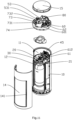
- the beneficial effects of the present invention are as follows: by pivoting the gas path body and the gas inlet body to the body mounting support, the water bottle joint and the gas cylinder interface can swing forward and backward relative to the body, so that the carbon dioxide gas cylinder and the soda bottle are obliquely mounted on the gas cylinder interface and the water bottle joint, and then the carbon dioxide gas cylinder and the soda bottle are swung to be reset into the gas cylinder cavity and the soda cavity, thereby achieving a larger space for a gripper and more convenient mounting.
- the soda machine allows the soda bottle to be closed in the soda cavity in the soda preparation process.
- the pressing surface cover provided on the top of the body can respectively drive the gas inlet pressure rod to allow the gas inlet rod to start the carbon dioxide gas cylinder for the gas supply of the soda bottle, or drive the driving rod to allow the gas vent valve to move in the gas vent cavity and thus open the gas vent passage and the gas vent hole for the gas venting of the soda bottle, thereby achieving simpler and more convenient operations.
- orientation statements such as orientation or position relationships indicated by up, down, front, back, left, right, etc., are based on the orientation or position relationships shown in the accompanying drawings and are only to facilitate the statement of the present invention and simplify the statement, rather than indicate or imply that the device or element referred to must have a specific orientation, be constructed and operate in a specific orientation, and therefore should not be understood as a limitation to the present invention.
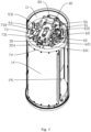
- a new soda machine comprises:
- the water bottle joint 37 and the gas cylinder interface 41 can swing forward and backward relative to the body 10, so that the carbon dioxide gas cylinder and the soda bottle are obliquely mounted on the gas cylinder interface 41 and the water bottle joint 37, and then the carbon dioxide gas cylinder and the soda bottle are swung to be restored into the gas cylinder cavity 13 and the soda cavity 12, thereby achieving a larger space for a gripper and more convenient mounting.
- the soda machine allows the soda bottle to be closed in the soda cavity 12 in the soda preparation process.
- the pressing surface cover 15 provided on the top of the body 10 can respectively drive the gas inlet pressure rod 53 to allow the gas inlet rod 45 to start the carbon dioxide gas cylinder for the gas supply of the soda bottle, or drive the driving rod 60 to allow the gas vent valve 32 to move in the gas vent cavity 31 and thus open the gas vent passage 311 and the gas vent hole 312 for the gas venting of the soda bottle, thereby achieving simpler and more convenient operations.
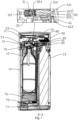
- a gas vent holder 61 located at the rear end of the gas path body 30 and facing the gas vent hole 312 is provided in the mounting cavity 11, and the gas vent holder 61 is pivoted on the body mounting support 20 so as to swing transversely relative to the gas path body 30; a first resetting member is provided on the gas vent holder 61, and a normal-state abutting position 611 and a reciprocating settling groove 613 located below the normal-state abutting position 611 and smoothly transitioning from the normal-state abutting position 611 are provided on the surface of the gas vent holder 61; a lower position is provided in the reciprocating settling groove 613; the gas vent valve 32 comprises a gas vent valve body 321, a gas vent valve head 322 located at the front end of the gas vent valve body 321 and used for blocking the gas vent passage 311, and a gas vent valve rod 323 located at the rear end of the gas vent valve body 321 and penetrating the gas vent hole 312 to extend to the
- the gas vent valve rod 323 Under a normal state, the gas vent valve rod 323 is abutted against the normal-state abutting position 611, so that the gas vent valve head 322 is jacked up at a port of the gas vent passage 311, thereby closing the gas vent passage 311. At this moment, the gas cannot be vented by the gas vent passage 311.
- one corresponding side of the pressing surface cover 15 is pressed to lift up the front end of the driving rod 60 and press downward the rear end of the driving rod.
- the gas vent holder 61 Since the driving rod 60 is pivoted in the mounting cavity 11 to be limited for supporting and vertical lifting, the gas vent holder 61 is driven to swing by the oblique driving pressure tank 612 so as to enable the gas vent valve rod 323 to enter the reciprocating settling groove 613 from the normal-state abutting position 611 and move to a lower point.
- the high gas pressure in the soda bottle pushes the gas vent valve 32 to move in the gas vent cavity 31, so that the gas vent valve head 322 leaves away from the gas vent passage 311 to open the gas vent passage 311.
- the gas in the soda bottle is vented for pressure relief along the gas vent passage 311-the gas vent cavity 31-the gas vent hole 312.
- the gas vent holder 61 is reset under the action of the first resetting member to enable the gas vent valve rod 323 to move and reset to the normal-state abutting position 611 along the reciprocating settling groove 613, thereby re-blocking the gas vent passage 311.
- the reciprocating settling groove 613 comprises a first slide 6131 and a second slide 6132 located at an end of the first slide 6131 and in communication with the first slide 6131; the front end of the first slide 6131 is lower than the surface of the gas vent holder 61 to form a first non-return surface, and an end of the first slide 6131 is higher than a starting end of the second slide 6132 to form a second non-return surface; an end of the second slide 6132 is smoothly guided to the normal-state abutting position 611, so that the user needs to enable the gas vent valve rod 323 to enter the second slide 6132 along the first slide 6131 before it is reset to the normal-state abutting position 611, thereby ensuring the gas venting efficiency.
- the user needs to completely press one end of the pressing surface cover 15 to drive an end portion of the gas vent valve rod 323 to enter the second slide 6132 so as to reset the gas vent valve 32 in the gas vent cavity 31.
- the front end of the gas vent valve head 322 is quasi-conically shaped.
- a fourth resetting member 602 is provided at the bottom of the rear end of the driving rod 60 so as to better drive the driving rod 60 and the gas vent holder 61 to reset.
- an elastic member 324 is provided between the gas vent valve body 321 and the gas vent valve head 322.
- the elastic member 324 provides a force toward the gas vent passage 311 to the gas vent valve head 322, so that after the gas pressure in the soda bottle is completely vented, the elastic member 324 can slightly push the gas vent valve head 322 onto the gas vent passage 311 and meanwhile reversely push the gas vent valve rod 323, thereby ensuring that the gas vent valve rod 323 is always abutted against the surface of the gas vent holder 61.
- a protective door track 70 located in the body 10 is provided at an upper end of the opening/closing door 14; the opening/closing door 14 moves transversely relative to the body 10 to open/close the soda cavity 12; the protective door track 70 is provided with a limit groove hole 71; a gas pressure lock is provided in the mounting cavity 11 and is preferably directly provided on the gas path body 30, and the gas pressure lock comprises a lock cavity 34 and a lock body 35 located in the lock cavity 34; a gas-guiding passage 341 extending to the intercommunication area is provided at the front end of the lock cavity 34, and a gas outlet hole 342 is provided at the rear end of the lock cavity 34; a front lock head 352 is provided at the front end of the lock body 35, and a rear lock head 353 used for closing the gas outlet hole 342 is provided at the rear end of the lock body 35; a lock rod 354 inserted in the gas vent hole 312 and extending to an outer side of the gas pressure lock is provided at the middle portion of the rear
- the carbon dioxide gas in the soda bottle forms a high pressure, it will be vented along the lock cavity 34 and the gas outlet hole 342, so that the high pressure state cannot be formed in the soda bottle to prepare soda.
- the protective door track 70 moves to the limit groove hole 71 and faces the lock rod 354.
- the lock rod 354 overlaps with the position of the limit groove hole 71 to push the lock rod 354 to be inserted into the limit groove hole 71 under the action of the gas pressure, so that the lock body 35 has a sufficient movement distance and the rear lock head 353 closes the gas outlet hole 342 along an inner side of the lock cavity 34.
- the gas in the soda bottle will no longer escape, thus forming the high pressure for preparing soda.
- This structure ensures that the soda machine cannot be operated normally when the opening/closing door 14 is not closed, thereby further ensuring safety.
- a limit part is provided on the gas inlet pressure rod 53, and a gas-filling limit block 73 is pivoted in the mounting cavity 11;
- the gas-filling limit block 73 comprises a driving end 731 at the front end and a limit end 732 at the rear end, and the limit end 732 movably accesses below the limit part under the swinging action of the driving end 731;
- the driving end 731 is located on the movement path of the protective door track 70 and partially overlaps with the protective door track 70 in a height direction;
- the protective door track 70 is abutted against the driving end 731 and lifts up the driving end 731 during movement; and a third resetting member driving the driving end 731 to reset downward is provided on the gas-filling limit block 73.
- the protective door track 70 moves to overlap with the driving end 731 to lift up the driving end 731, so that the limit end 732 of the gas-filling limit block 73 is displaced in the horizontal direction to enter a lower end of the limit part of the gas inlet pressure rod 53 and thus limit the downward press of the gas inlet pressure rod 53. Therefore, the gas inlet pressure rod 53 cannot open the carbon dioxide gas cylinder and accordingly cannot enter a gas inlet mode.
- the limit part is a limit plate 531 independently provided on the gas inlet pressure rod 53.
- a lock notch 72 is provided on the protective door track 70
- a mechanical door latch 601 located on the movement path of the protective door track 70 and used for being clamped into a latch fastener is provided at the front end of the driving rod 60
- a guide surface is provided at an edge of the mechanical door latch 601
- a connecting frame 62 is provided at a lower end of the pressing surface cover 15, and an upper lifting rod 621 located at the front end of a driving tube and used for lifting up the front end of the driving rod 60 is provided on the connecting frame 62.
- the mechanical door latch 601 moves along the surface of the protective door track 70 to be clamped into the lock notch 72, thereby locking the opening/closing door 14 and preventing the opening/closing door 14 from being opened when the soda machine is operated.
- the pressing surface cover 15 is pressed to lift up the front end of the driving rod 60 to operate the gas vent valve 32.
- the driving rod 60 synchronously lifts up the mechanical door latch 601 from the lock notch 72.
- the second resetting member 351 drives the lock body 35 to move toward the front end of the lock cavity 34 to detach the lock rod 354 from the limit groove hole 71, so that the opening/closing door 14 can be opened normally.
- the opening/closing door 14 cannot be opened when the soda machine is operated.
- the track 74 located at an upper end and/or a lower end of the opening of the soda cavity 12 is provided on the body 10, and an upper end and/or a lower end of the opening/closing door 14 is mounted on the track 74 so as to more smoothly slide to open/close the soda cavity 12.
- the track 74 is located at the upper end of the opening of the soda cavity 12.
- a first notch corresponding to the limit groove hole 71, a second notch corresponding to the driving end 731 and configured for locating the driving end 731 therein and a third notch corresponding to the lock notch 72 are provided on the track 74.
- the protective door track 70 is inserted into the track 74, and the opening/closing door bracket 75 is provided at the bottom of the body 10.
- the opening/closing door bracket 75 is connected to a lower end of the opening/closing door 14, and an end portion of the opening/closing door bracket 75 is pivoted to the bottom of the body 10 to assist the opening/closing door 14 to swing transversely on the body 10 to open/close the soda cavity 12.
- the reset torsion spring 76 connected to the opening/closing door bracket 75 is provided on the body 10, the gear groove 77 is provided on the opening/closing door bracket 75, and the rack 78 is provided on the gear groove 77.
- a one-way damping gear 79 engaged with the rack 78 is provided in the body 10, and a protective door hiding cavity located at a side of a protective door and configured for the protective door to enter therein is provided on the body 10.
- the reset torsion spring 76 drives the opening/closing door bracket 75 to rotate, thereby driving the opening/closing door 14 to be automatically transversely opened, and the single damping gear 79 buffers and limits the opening speed of the opening/closing door 14, thereby slowing down the opening speed of the opening/closing door 14 and reducing the impact effect generated when the opening/closing door 14 is opened.
- soft cushioning rubber pads used for being abutted against the edge of the opening/closing door 14 are provided at an inner side of the opening of the soda cavity 12 and an inner side wall of the opening/closing door hiding cavity.
- a handle 141 is provided on the surface of the opening/closing door 14 to facilitate the operation of the opening/closing door 14.
- the track 74 may not be provided, but two sets of opening/closing door brackets 75 arranged above and below the body 10 are used for limiting and assisting the movement trajectory of the opening/closing door 14.
- pivot frames 23 are provided on two sides of the first mounting hole, and first pivot shafts 39 pivoted on the pivot frames 23 are provided on two sides of the gas path body 30.
- the method for pivoting the gas path body 30 on the first mounting hole can be also as follows: shaft holes are provided at a side wall of the first mounting hole and a side wall of the gas path body 30, and one rotating shaft is inserted into the shaft hole members of the side wall of the first mounting hole and the side wall of the gas path body to achieve the pivoting effect.
- a swing track 24 is provided on one side of the pivot frame 23 toward the gas path body, and at least two locating holes 25 smoothly transitioning from an inner surface of the track 74 are provided on an inner surface of the swing track 24; mounting channels 391 are provided on two sides of the gas path body 30, and a dial shaft 392 with a cambered front end is provided in the mounting channel 391; and an ejection spring located at the rear end of the dial shaft 392 is provided in the mounting channel 391, and the front end of the dial shaft 392 is inserted in the swing track 24 and can access the locating hole 25 under the action of an external force.
- the swing track 24 can limit the swinging range of the gas path body 30 and meanwhile play a role in assisting the gas path body 30 to swing.
- a limit groove is provided at the rear end of the inner wall of the mounting channel 391, and a limit boss inserted into the limit groove is provided on the rear end surface of the dial shaft 392.
- the limit boss is inserted into the limit groove, thereby limiting the movement distance of the dial shaft 392 in the mounting channel 391 and preventing the dial shaft 392 from being detached from the mounting channel 391.
- the limiting boss has a wedge shape that gradually thickens from the rear end of the dial shaft 392 toward the front end.
- the dial shaft 392 is implemented as a spherical roll ball.
- the body mounting support 20 comprises a main frame and a sub-frame 21 mounted on the main frame.
- the first mounting hole and the pivot frame 23 are both provided on the sub-frame 21.
- the gas path body 30 is mounted on the sub-frame 21, and then the sub-frame 21 is mounted at the bottom of the main frame, thereby facilitating production and mounting.
- an upper protective cover covered on the upper end of the gas path body 30 is provided on the body mounting support 20.
- second pivot holes 22 located on two sides of the second mounting hole and having upper openings are provided on the body mounting support 20, and second pivot shafts 42 mounted in the second pivot holes 22 along the upper openings are provided on two sides of the gas inlet body 40;
- a connecting rod bracket 50 capped on an upper end of the second pivot hole 22 is provided on the body mounting support 20, an elastic rod 51 extending into the second mounting hole is provided at a lower end of the connecting rod bracket 50, and an elastic hook 52 facing the gas inlet body 40 is provided at an end portion of the elastic rod 51;
- a groove 43 is vertically provided on a rear end surface of the gas inlet body 40, a raised limit stopper 44 is provided on the bottom surface of the groove 43, and two side surfaces of the elastic hook 52 are fitted with two side surfaces of the limit stopper 44 to jointly form an inclined abutting-pushing surface that drives the elastic rod 51 to deform toward an outer side of the gas inlet body 40; the gas inlet body 40 during a swinging process enables the elastic hook 52 to be respectively
- the limit block 44 is driven to swing synchronously, so that the limit block 44 squeezes the elastic hook 52 and thus drives the elastic rod 51 to deform in a direction away from the gas inlet body 40, thereby causing the elastic hook 52 to cross the limit block 44 to the other side.
- the gas inlet body 40 is provided with two modes for fixation, respectively a normal operating mode in which the gas inlet body 40 is under a vertical state and a gas cylinder mounting mode in which the gas inlet body 40 is under an oblique state.
- the angle between the two side surfaces of the limit block 44 and the inner surface of the groove 43 is an obtuse angle.
- the front end of the gas inlet pressure rod 53 is located below the front end of the pressing surface cover 15. When the front end of the pressing surface cover 15 is pressed, the front end of the pressing surface cover 15 synchronously drives the gas inlet pressure rod 53 to be pressed downward, and then the carbon dioxide gas cylinder is started for gas inletting by the gas inlet rod 45.
- the pressing surface cover 15 is not in contact with the front end of the driving rod 60, but when the rear end of the pressing surface cover 15 is pressed, the front end of the pressing surface cover 15 is tilted upward and thus the connecting frame 62 drives the driving rod 60 to swing so as to perform gas venting.
- a pressing needle 532 located directly above the gas inlet rod 45 is provided at the bottom of the gas inlet pressure rod 53. Only when the gas inlet body 40 is under the normal operating mode, the gas inlet rod 45 is just at the bottom of the pressing needle 532 and thus can be driven by the gas inlet pressure rod 53 to be pressed downward. When the gas inlet body 40 swings toward the outer side of the body to be used for mounting the carbon dioxide gas cylinder, the gas inlet rod 45 and the pressing needle 532 are misaligned at this moment, so that the gas inlet rod 45 cannot be pressed downward.
- a clamping notch 131 for fixing the carbon dioxide gas cylinder is provided at the bottom of the gas cylinder cavity 13, so that the carbon dioxide gas cylinder can be further fixed by the clamping notch 131.
- a gravity cavity 33 is vertically provided on the gas path body 30, and a gravity hole 331 extending to the intercommunication area is provided at the bottom of the gravity cavity 33; a gravity vent hole 332 is provided at the top of the gravity cavity 33, and a gravity valve body 333 liftable in the gravity cavity 33 is provided in the gravity cavity 33; a gas guide gap is formed between the gravity valve body 333 and a side wall of the gravity cavity 33; and a gravity valve head 3331 enclosing the gravity vent hole 332 when the gravity valve body 333 is jacked up is provided at the top of the gravity valve body 333, and a gas guide groove 3332 is provided at the bottom of the gravity valve body 333 and/or on the bottom surface of the gravity cavity 33.
- a gravity valve Due to the existence of a gravity valve, in the process of mounting the soda bottle on the soda machine for storage, if the carbon dioxide gas cylinder has gas leakage by the gas inlet body 40, the gas pressure generated by the slowly leaking carbon dioxide gas is insufficient to jack up the gravity valve body 333, so that the carbon dioxide gas is naturally vented along the gravity hole 331-the gravity cavity 33-the gravity vent hole 332, thereby preventing the soda bottle from forming a high-pressure state due to gas leakage during storage.
- the high-pressure gas jacks up the gravity valve body 333, causing the gravity valve head 3331 to block the gravity vent hole 332, so that the gas pressure in the soda bottle can be increased normally.
- the function of a gas guide groove 3332 is to enable the gas to flow better when the gravity valve body 333 falls on the bottom of the gravity cavity 33 due to gravity.
- a pressure relief cavity 36 is provided on the gas path body 30.
- a pressure relief channel 361 extending to the intercommunication area and a pressure relief hole 362 in communication with the outer side of the gas path body 30 are provided at two ends of the pressure relief cavity 36, respectively.
- a pressure relief valve 363 is provided in the pressure relief cavity 36, and a pressure relief gap is formed between the pressure relief valve 363 and the pressure relief hole 362.
- a head of the pressure relief valve 363 used for closing the pressure relief channel 361 is provided at an end of the pressure relief valve 363.
- a fifth resetting member 364 used for pressing the pressure relief valve 363 on the pressure relief channel 361 is provided on an end portion of the pressure relief valve 363.
- the gas pressure in the soda bottle When the gas pressure in the soda bottle is too high, the gas pressure in the soda bottle pushes the pressure relief valve 363 to conquer the resetting pressure of the fifth resetting member 364, thereby opening the pressure relief channel 361 and venting the gas in the soda bottle along the pressure relief hole 362. Dynamic balance is formed between the fifth resetting member 364 and the gas pressure in the soda bottle, thereby ensuring the gas pressure in the soda bottle.
- a limit bracket 80 is mounted on the body mounting support 20.
- a reset push rod 81 used for being abutted against the bottom surface of the pressing surface cover 15 is provided on the limit bracket 80.
- a reset spring used for driving the reset push rod 81 to move upward is provided at the bottom of the reset push rod.
- the gas inlet pressure rod 53 may indirectly drive the gas inlet pressure rod 45 to be pressed downward.
- an inching switch is provided at the lower end of the gas inlet pressure rod 53.
- the inching switch is electrically connected to a driving motor, and the driving motor is connected to the gas inlet rod 45, so that when the gas inlet pressure rod 53 is pressed downward to touch the inching switch, the driving motor drives the gas inlet rod 45 to be pressed downward.
- the first resetting member, the second resetting member 351, the third resetting member, the fourth resetting member 602 and the fifth resetting member 364 are all preferably in the implementation form of springs, and may also be selected as elastic columns, a group of mutually exclusive magnets and other implementation forms.
Landscapes
- Engineering & Computer Science (AREA)
- Food Science & Technology (AREA)
- Chemical & Material Sciences (AREA)
- Chemical Kinetics & Catalysis (AREA)
- Health & Medical Sciences (AREA)
- Nutrition Science (AREA)
- Life Sciences & Earth Sciences (AREA)
- Polymers & Plastics (AREA)
- Pressure Vessels And Lids Thereof (AREA)
- Accommodation For Nursing Or Treatment Tables (AREA)
- Toys (AREA)
Applications Claiming Priority (2)
| Application Number | Priority Date | Filing Date | Title |
|---|---|---|---|
| CN202210692748.7A CN114983233B (zh) | 2022-06-17 | 2022-06-17 | 一种气泡水机 |
| PCT/CN2022/118177 WO2023240810A1 (zh) | 2022-06-17 | 2022-09-09 | 一种新型气泡水机 |
Publications (2)
| Publication Number | Publication Date |
|---|---|
| EP4382007A1 true EP4382007A1 (de) | 2024-06-12 |
| EP4382007A4 EP4382007A4 (de) | 2025-08-27 |
Family
ID=83034851
Family Applications (1)
| Application Number | Title | Priority Date | Filing Date |
|---|---|---|---|
| EP22946483.9A Pending EP4382007A4 (de) | 2022-06-17 | 2022-09-09 | Neue vorrichtung zur herstellung von kohlensäurehaltigem wasser |
Country Status (3)
| Country | Link |
|---|---|
| EP (1) | EP4382007A4 (de) |
| CN (1) | CN114983233B (de) |
| WO (1) | WO2023240810A1 (de) |
Families Citing this family (1)
| Publication number | Priority date | Publication date | Assignee | Title |
|---|---|---|---|---|
| CN121288400B (zh) * | 2025-12-11 | 2026-02-27 | 宁波龙巍环境科技有限公司 | 一种用于净水器的滤芯安装结构 |
Family Cites Families (20)
| Publication number | Priority date | Publication date | Assignee | Title |
|---|---|---|---|---|
| US5870944A (en) * | 1997-01-03 | 1999-02-16 | International Home Beverage Supply Co., Inc. | Carbonated beverage making apparatus and method |
| JP2005245475A (ja) * | 2004-03-01 | 2005-09-15 | Tiger Vacuum Bottle Co Ltd | 飲料用粉茶等排出器 |
| JP2006034919A (ja) * | 2004-07-26 | 2006-02-09 | Seisuke Takeshita | 電気コーヒーメーカー |
| IT1398056B1 (it) * | 2010-02-04 | 2013-02-07 | De Longhi Appliances Srl | Macchina da caffe' automatica |
| EP3000363A1 (de) * | 2014-09-24 | 2016-03-30 | Qbo Coffee GmbH | Milchschäumergerät, Getränkezubereitungssystem und Getränkezubereitungsmaschine |
| JP2019051288A (ja) * | 2017-09-14 | 2019-04-04 | アイリスオーヤマ株式会社 | 密閉容器 |
| CN211066194U (zh) * | 2019-11-25 | 2020-07-24 | 佛山市南海喜泡科技有限公司 | 一种操作简易并具有隐藏式排气键的气泡水机 |
| CN211632831U (zh) * | 2019-12-25 | 2020-10-09 | 苏州依卡蒂运动器材有限公司 | 一种气泡水机智能安全保护装置 |
| CN213097517U (zh) * | 2020-08-06 | 2021-05-04 | 唯赛勃环保设备有限公司 | 一种气泡水打气结构 |
| CN112386110B (zh) * | 2020-11-30 | 2024-09-03 | 江门市伊科迈特电子科技有限公司 | 一种气泡水制造机 |
| DE202021100698U1 (de) * | 2021-02-11 | 2021-03-01 | Delta-Sport Handelskontor Gmbh | Vorrichtung zum Versetzen einer Flüssigkeit mit einem Gas |
| CN113116141B (zh) * | 2021-03-30 | 2022-06-10 | 绍兴摩纳净水科技有限公司 | 一种气泡机 |
| CN112890595B (zh) * | 2021-04-08 | 2025-07-25 | 珠海格力电器股份有限公司 | 气泡水机 |
| CN216494863U (zh) * | 2021-08-31 | 2022-05-13 | 佛山市顺德区美的饮水机制造有限公司 | 气泡水模块和具有其的多功能饮水机 |
| CN113598603B (zh) * | 2021-09-18 | 2025-03-25 | 珠海格力电器股份有限公司 | 气泡水机 |
| CN216652045U (zh) * | 2021-10-13 | 2022-06-03 | 浙江鸿丰精工科技有限公司 | 一种气泡水机上的进气控制机构 |
| CN217185673U (zh) * | 2021-11-17 | 2022-08-16 | 江门市伊科迈特电子科技有限公司 | 一种具有自动加气和余量检测功能的气泡水机 |
| CN217185697U (zh) * | 2022-03-24 | 2022-08-16 | 江门市伊科迈特电子科技有限公司 | 一种便于加气的气泡水机 |
| CN217827523U (zh) * | 2022-06-17 | 2022-11-18 | 江门市伊科迈特电子科技有限公司 | 一种新型气泡水机 |
| CN114983229B (zh) * | 2022-06-17 | 2025-06-20 | 江门市伊科迈特电子科技有限公司 | 一种按压式排气进气的气泡水机 |
-
2022
- 2022-06-17 CN CN202210692748.7A patent/CN114983233B/zh active Active
- 2022-09-09 WO PCT/CN2022/118177 patent/WO2023240810A1/zh not_active Ceased
- 2022-09-09 EP EP22946483.9A patent/EP4382007A4/de active Pending
Also Published As
| Publication number | Publication date |
|---|---|
| CN114983233A (zh) | 2022-09-02 |
| WO2023240810A1 (zh) | 2023-12-21 |
| CN114983233B (zh) | 2025-06-10 |
| EP4382007A4 (de) | 2025-08-27 |
Similar Documents
| Publication | Publication Date | Title |
|---|---|---|
| EP4382007A1 (de) | Neue vorrichtung zur herstellung von kohlensäurehaltigem wasser | |
| CN109361983A (zh) | 无线耳机充电盒 | |
| CN209413460U (zh) | 一种隐藏弹出机构及使用该机构的门把手 | |
| CN108438936B (zh) | 一种能够降低粮食破碎率的粮食入仓缓冲装置 | |
| US20240001313A1 (en) | Carbonator of user-friendly design and method of carbonating a beverage | |
| CN217827523U (zh) | 一种新型气泡水机 | |
| CN210788706U (zh) | 一种金属板折弯装置 | |
| CN112141861B (zh) | 一种家用电梯自动平开门 | |
| CN114983229A (zh) | 一种按压式排气进气的气泡水机 | |
| CN212839698U (zh) | 一种矿用自锁式球阀 | |
| CN211900215U (zh) | 人行通道自动门装置 | |
| CN220374408U (zh) | 一种双控翻转扶手箱机构及工程机械 | |
| CN211524552U (zh) | 一种推拉平开两用铝合金门 | |
| CN217792544U (zh) | 一种按压式排气进气的气泡水机 | |
| CN218942905U (zh) | 具有防爆联动保护功能的气泡水机 | |
| CN111042665B (zh) | 一种语音识别防盗锁 | |
| CN114916823B (zh) | 一种具有安全门的气泡水机 | |
| CN208761957U (zh) | 物料提升机 | |
| CN111569341A (zh) | 一种消防灭火水带固定设备 | |
| KR20010049427A (ko) | 승강식 수납 유닛 | |
| CN218434424U (zh) | 用于电梯门的关门保持装置 | |
| CN221089665U (zh) | 一种防掉落的卡位机构及成型机 | |
| CN215704770U (zh) | 一种防爆钢化玻璃 | |
| CN113251274A (zh) | 一种液晶显示屏辅助固定装置 | |
| CN113028129A (zh) | 一种具有防盗机构的缓冲型闸阀 |
Legal Events
| Date | Code | Title | Description |
|---|---|---|---|
| STAA | Information on the status of an ep patent application or granted ep patent |
Free format text: STATUS: THE INTERNATIONAL PUBLICATION HAS BEEN MADE |
|
| PUAI | Public reference made under article 153(3) epc to a published international application that has entered the european phase |
Free format text: ORIGINAL CODE: 0009012 |
|
| STAA | Information on the status of an ep patent application or granted ep patent |
Free format text: STATUS: REQUEST FOR EXAMINATION WAS MADE |
|
| 17P | Request for examination filed |
Effective date: 20240308 |
|
| AK | Designated contracting states |
Kind code of ref document: A1 Designated state(s): AL AT BE BG CH CY CZ DE DK EE ES FI FR GB GR HR HU IE IS IT LI LT LU LV MC MK MT NL NO PL PT RO RS SE SI SK SM TR |
|
| REG | Reference to a national code |
Ref country code: DE Ref legal event code: R079 Free format text: PREVIOUS MAIN CLASS: A47J0031400000 Ipc: B01F0023236000 |
|
| A4 | Supplementary search report drawn up and despatched |
Effective date: 20250730 |
|
| RIC1 | Information provided on ipc code assigned before grant |
Ipc: B01F 23/236 20220101AFI20250724BHEP Ipc: B01F 23/2361 20220101ALI20250724BHEP Ipc: A23L 2/54 20060101ALI20250724BHEP |
|
| DAV | Request for validation of the european patent (deleted) | ||
| DAX | Request for extension of the european patent (deleted) |