EP4381256B1 - Auf einem müllwagen installierbares system zum wiegen von müllbehältern, zugehörige verwendung und müllwagen - Google Patents
Auf einem müllwagen installierbares system zum wiegen von müllbehältern, zugehörige verwendung und müllwagen Download PDFInfo
- Publication number
- EP4381256B1 EP4381256B1 EP22812576.1A EP22812576A EP4381256B1 EP 4381256 B1 EP4381256 B1 EP 4381256B1 EP 22812576 A EP22812576 A EP 22812576A EP 4381256 B1 EP4381256 B1 EP 4381256B1
- Authority
- EP
- European Patent Office
- Prior art keywords
- pick
- garbage
- comb
- load cell
- arm
- Prior art date
- Legal status (The legal status is an assumption and is not a legal conclusion. Google has not performed a legal analysis and makes no representation as to the accuracy of the status listed.)
- Active
Links
Images


Classifications
-
- G—PHYSICS
- G01—MEASURING; TESTING
- G01G—WEIGHING
- G01G19/00—Weighing apparatus or methods adapted for special purposes not provided for in the preceding groups
- G01G19/08—Weighing apparatus or methods adapted for special purposes not provided for in the preceding groups for incorporation in vehicles
- G01G19/083—Weighing apparatus or methods adapted for special purposes not provided for in the preceding groups for incorporation in vehicles lift truck scale
-
- B—PERFORMING OPERATIONS; TRANSPORTING
- B65—CONVEYING; PACKING; STORING; HANDLING THIN OR FILAMENTARY MATERIAL
- B65F—GATHERING OR REMOVAL OF DOMESTIC OR LIKE REFUSE
- B65F3/00—Vehicles particularly adapted for collecting refuse
- B65F3/02—Vehicles particularly adapted for collecting refuse with means for discharging refuse receptacles thereinto
- B65F3/04—Linkages, pivoted arms, or pivoted carriers for raising and subsequently tipping receptacles
- B65F3/041—Pivoted arms or pivoted carriers
-
- B—PERFORMING OPERATIONS; TRANSPORTING
- B65—CONVEYING; PACKING; STORING; HANDLING THIN OR FILAMENTARY MATERIAL
- B65F—GATHERING OR REMOVAL OF DOMESTIC OR LIKE REFUSE
- B65F3/00—Vehicles particularly adapted for collecting refuse
- B65F3/02—Vehicles particularly adapted for collecting refuse with means for discharging refuse receptacles thereinto
- B65F2003/022—Vehicles particularly adapted for collecting refuse with means for discharging refuse receptacles thereinto the discharging means comprising a device for determining the weight of the content of refuse receptacles
-
- B—PERFORMING OPERATIONS; TRANSPORTING
- B65—CONVEYING; PACKING; STORING; HANDLING THIN OR FILAMENTARY MATERIAL
- B65F—GATHERING OR REMOVAL OF DOMESTIC OR LIKE REFUSE
- B65F3/00—Vehicles particularly adapted for collecting refuse
- B65F3/02—Vehicles particularly adapted for collecting refuse with means for discharging refuse receptacles thereinto
- B65F2003/0223—Vehicles particularly adapted for collecting refuse with means for discharging refuse receptacles thereinto the discharging means comprising elements for holding the receptacle
- B65F2003/024—Means for locking the rim
-
- B—PERFORMING OPERATIONS; TRANSPORTING
- B65—CONVEYING; PACKING; STORING; HANDLING THIN OR FILAMENTARY MATERIAL
- B65F—GATHERING OR REMOVAL OF DOMESTIC OR LIKE REFUSE
- B65F3/00—Vehicles particularly adapted for collecting refuse
- B65F3/02—Vehicles particularly adapted for collecting refuse with means for discharging refuse receptacles thereinto
- B65F2003/0223—Vehicles particularly adapted for collecting refuse with means for discharging refuse receptacles thereinto the discharging means comprising elements for holding the receptacle
- B65F2003/0243—Means for locking the side, e.g. via spigots or trunnion pins
Definitions
- the present disclosure concerns a system installable on a garbage truck for weighing garbage containers, particularly for weighing a plurality of garbage container pickup (pick-up, pick up) types.
- the present disclosure also concerns a related use of said system, and a garbage truck comprising said system.
- the present disclosure relates to systems (machinery) and methods for picking up or collecting garbage (trash) and the like, involving weighing the garbage.
- garbage trucks which integrate systems for measuring the weight of garbage containers being picked up by the garbage truck. Weighing a garbage container serves the purpose of measuring or estimating the weight of the garbage in the container, as is often required by the authorities and/or the regulations or norms related to the garbage collection process. It is also known that there exist several types of garbage containers which differ from each other by their physical features which allow for the garbage container in each case to be picked up, i.e. be held and raised, by a garbage truck.
- such features of said garbage containers include the garbage container having a particular shape for fitting a collection mechanism of the garbage truck, or include the garbage truck having at its surface other features such as protrusions, recessions or other metallic or plastic parts, so that said features can be coupled to corresponding parts of the pick-up (lifting) mechanism of a garbage truck.
- Said garbage container's features which define the way by which the garbage truck can pick up the garbage container define the pick-up type of the garbage container.
- the garbage container may also be of two or more pick-up (pick up) types, i.e. the container may comprise features which may allow the pick-up of the container by two or more, respectively, types of lifting mechanisms.
- each of the previously known garbage trucks which have a lifting mechanism which is capable of weighing is able to pick up only one pick-up type of garbage containers. This is an important problem considering that a garbage truck may have to operate inside or between different areas which have garbage containers of different pickup (pick-up) types.
- the respective systems which pick up and weigh the containers are permanently integrated in the truck's structure, it is not easy adapt said trucks when there is need of changing the pick-up type of the containers that need to be processed, and this is an important problem.
- the present disclosure solves the aforementioned problems because it offers a system which simultaneously, i) is capable of weighing and picking up two pickup (pick-up) types of garbage containers; ii) it may be used with existing garbage trucks for allowing said trucks to weighing garbage containers of different pick-up types; iii) it may improve the operability and reliability of the garbage truck so that it can still be operable, at least to some extent, when due to a damage of the system it cannot be operated with containers of one pickup type. Solving said problems may in turn reduce the costs associated with the garbage collection process involving said system, improve the procedural efficiency and reduce the time required for the garbage collection process, and positively impact the environment, at least due to the improved functionality that the system confers to the garbage trucks with which the system is used.
- the present invention in its first aspect concerns a system which is installable on a garbage truck for weighing a plurality of garbage container types, and comprises: an arm configured for supporting a garbage container of a plurality of types; a pick-up device located at an end of the arm and configured to engage and hold a trunnion of a garbage container of a first pickup type; a pick-up comb configured to engage and hold a lip of a garbage container of a second pick-up type; at least two load cells of which a first one is connected to the pick-up device and the second one is connected to the pick-up comb, wherein the first load cell is configured to measure a weight exerted on the pick-up device when the latter engages the garbage container of the first pickup type, and the second load cell is configured to measure a weight exerted on the pick-up comb when the latter engages the garbage container of the second pickup type; at least one motion sensor configured to record movement related to a collection of the garbage container of the first or second pickup type by the
- the pick-up comb is attached either along the arm or at another end of the arm opposite the end where the pick-up device is located. It is noted that the pickup device may also be called trunnion adapter, and the pick-up comb may also be called comb lifting device or comb.
- the invention can provide excellent weighing accuracy, as it can be adapted to the point of contact with the garbage, as a result of which it is possible to avoid adding to the measurements the weight of the rest of the collection mechanism of the truck, and also, the system allows for preferably using load cells with a relatively small measurement range, increasing the accuracy and resolution of the measurement.
- the aforementioned system can advantageously be used with a garbage container of the first or of the second pickup type. Likewise, it can be used with a garbage container which comprises both the aforementioned lip and trunnion and, hence, is both of the first and second pickup type.
- the load cells of the system generally allow for measuring the weight of the garbage container, and hence, for estimating the weight of the garbage (trash) which is contained in the garbage container.
- this functionality is available regardless of whether the garbage container is engaged using the pick-up device or the pick-up (pickup) comb, and therefore, said functionality is not compromised when having to switch between using the pick-up device and the pick-up (pickup) comb.
- the measurements offered by the motion sensor and the inclination sensor may be used for monitoring the pickup process, in particular the action of turning over the garbage container as is usually done during pickup depending on the types of said garbage container and truck.
- said motion and inclination (tilt) measurements may be used for enabling or improving the accuracy of the weight measurements because the latter may depend on factors such as the inclination of the vehicle relatively to the ground, the position or inclination of the garbage container at the time of the measurement, the potential movement of the garbage inside the container during the handling of the container by the garbage truck, or another factor. Said factors may be taken into account by using appropriate algorithms which in some preferred embodiments of the invention are processed using the electronic device.
- the at least one electronic device is operationally connected to at least a corresponding one of each of the at least one motion sensor, the at least two load cells, and the at least one inclination sensor.
- the electronic device is operationally connected to the sensors and includes a logic that provides the measured of estimated weights
- the data related to said measurements may be processed in another controller or logic, and then passed to the aforementioned electronic device, in which case, the electronic device primarily serves its important functionality of transmitting the data.
- the data may most preferably relate to the measurements from the sensors or may be or include other type of data related to the operation of the system.
- the transmission of the data preferably said transmission being a wireless one, may allow for the system's user(s) to gather and further process said data.
- the system further comprises a third load cell connected to the pick-up comb, wherein the third load cell is configured to measure a weight exerted on the pick-up comb when the latter engages the garbage container of the second pickup type, the third load cell being at a distance from the second load cell such that the second and the third load cells can measure a load distribution along the pick-up comb. Measuring the load distribution along the pick-up comb may improve the accuracy of the weight measurement, especially when the garbage is unevenly distributed within the garbage container.
- the system further comprises a bar which is located and configured to contact and push the garbage container of the first or second pickup type at a point of the container, such that, when the garbage container is at an operational position on a ground and is engaged by the pick-up device or the pick-up comb, said point of the container contacting the bar is located lower with respect to the points of contact of the container with said pick-up device or pick-up comb, respectively.
- Said bar can be called pushing pad, and is useful for turning over the container during the garbage collection process, because it may push said container from the container's part that is initially closer to the ground.
- the system further comprises an additional load cell connected to the bar and configured to measure a weight exerted on the bar when the latter pushes the garbage container.
- the load cell at the bar can aid monitoring the process which causes the weight distribution in the container to change.
- the system further comprises two or more load cell distortion limiters, and each load cell is connected to a corresponding one of the load cell distortion limiters, each load cell distortion limiter supporting and being configured to limit the distortion of the corresponding load cell when said distortion is above a threshold value.
- the distortion limiter generally serves the purpose of avoiding, preventing or simply reducing the possibility of damaging the load cell to which the distortion limiter is connected.
- the threshold value is usually provided by the manufacturer of the load cell and/or of the load cell distortion limiter.
- the load cell distortion limiter is also known as "overload protection" which is a term often used by manufacturers of load cells which are often coupled and being provided with some type of overload protection.
- the system's at least one motion sensor comprises any of an inertial measurement unit, an accelerometer, a gyroscope, an inclinometer, a magnetometer, or another type of sensor.
- the system comprises an inertial measurement unit which may comprise or act as the at least one motion sensor and the at least one inclinometer of the system.
- the use of the inertial measurement unit may advantageously offer accurate motion and tilt measurements, and may facilitate the fabrication of the system, and in particular, may facilitate the fabrication and integration in the system of the components related to the aforementioned motion and inclination measurements.
- the at least one motion sensor comprises an inertial measurement unit, or the system comprises an inertial measurement unit (IMU) which comprises the motion and/or the inclination sensor.
- the system may optionally comprise two or more IMUs, e.g. the system may have one IMU at the pick-up device, and a second IMU at the pick-up comb.
- the system further comprises one or more Radio-frequency identification (RFID) readers which is/are part of, or is/are operationally connected to, the at least one electronic device.
- RFID Radio-frequency identification
- the system comprises one RFID reader which is integrated with/in a tooth of the pick-up comb.
- the system comprises two RFID readers of which one is integrated with the tooth of the pick-up comb and the other is integrated with the arm.
- the system comprises an RFID reader which is integrated with the pick-up comb or within a tooth of the pick-up comb, and comprises two antennas which are pointed (directed) towards two respective direction which are normal to each other.
- the first of said two antennas is directed towards a first direction that is towards a part of the garbage container when the pick-up comb engages the garbage container
- the second antenna is directed to a second direction that is normal or, more generally, forms a non-zero angle with the first direction, so that said second direction is towards said part of the garbage container when the latter is engaged by the pick-up device.
- the fist antenna is directed towards the container's lip that is engageable by the pick-up comb (the comb lifting device)
- the second antenna may be directed towards a different part of the container and serves to identify the container when the latter is engaged by the pickup device (the trunnion adapter).
- the garbage container's part(s) towards which said antennas are directed have RFID tag(s) for identifying the container.
- the system's electronic device is connectable with, or comprises, preferably within a housing of the electronic device, any of an RFID reader for bin identification, means for identifying bins, means for GNSS satellite positioning, means for wireless communication (e.g. via a GSM system), means for interfacing with and downloading data from a tachograph, means for interfacing with and downloading data from a CAN bus (a Controller Area Nextwork), means for interfacing with and downloading data from an on-board diagnostics, an on board diagnostics (OBD) system, or a combination thereof.
- GSM Global System for Mobile Communications
- CAN bus a Controller Area Nextwork
- OBD on board diagnostics
- the system further comprises one or more electronic units.
- Each electronic unit may comprise one or more of each of the at least one electronic device, the at least one inclination sensor and the at least one electronic device of the system.
- the electronic unit comprises at least a set of an inclination sensor, a motion sensor and an electronic device of the system.
- the components of the electronic unit are preferably within a case of said electronic unit, so that the latter is compact and can be installed as a whole on the pick-up device, or on the pick-up comb or elsewhere at the system.
- the aforementioned electronic unit further comprises an RFID reader which is part of, or is operationally connected to, the electronic device, and this RFID reader may be as described further above.
- the system comprises an electronic unit, and the latter also comprises an RFID reader which comprises two antennas. These two antennas may be directed towards different directions as described further above.
- said electronic unit having the two antennas is (located) at a tooth of the pick-up comb.
- the system comprises two electronic units of which one is integrated with the pick-up comb, or the arm, or the pick-up device.
- the at least one motion sensor includes an accelerometer and an inertial measurement unit.
- the pick-up comb is integrated with the arm.
- the pick-up comb is removably attached to the arm.
- Said arm may be already installed to the garbage truck before attaching to it the pickup comb.
- the second load cell may be at a connection between the pick-up comb and the arm or maybe at an optionally present additional structure or frame which may be configured to support the pick-up comb and/or the arm.
- Said additional structure or frame may be an optional part of the pick-up comb.
- the system further comprises a base connected to the arm, the base and the pick-up device being at opposed ends of the arm, the base preferably comprising a pin and a bushing configured to enable a rotation of the arm.
- the base is located at said additional structure or frame such that it allows that the arm can rotate or pivot about the base. This way the pick-up device attached to the rotatable arm may move closer to, or away from, the pick-up comb, depending on whether the system is to engage the garbage truck using the pick-up comb or the pick-up device, respectively.
- the pick-up comb is attached along the arm, the latter and the pick-up comb are lengthwise substantially parallel to each other.
- the system further comprising a proximity sensor.
- the system comprises said optional proximity sensor
- the latter is configured to detect a rotation, a closure or a retraction of the arm towards a garbage truck when the system is operationally installed on the garbage truck, preferably the proximity sensor being operationally connected to the electronic device.
- the system comprises said optional proximity sensor
- the latter is an inductive sensor.
- the proximity sensor may be very useful when the arm can pivot about a base, as for example is described further above, for detecting whether the arm is at a first position where the garbage container can be engaged by the trunnion adapter (the pick-up device), or is at second position where said container can be engaged by the pick-up comb.
- said proximity sensor can be used for triggering the electronic device to stop or start using the load cells attached to the pick-up comb or the pick-up device for measuring the weight of the garbage container.
- the latter is configured to detect a locking of the garbage container by the system, said locking comprising the system applying a pressure on the garbage container, and the proximity sensor is further configured to trigger the electronic device to disregard or prevent weight measurements during said locking process.
- the system may optionally comprise a locking bar which during the collection process may press against the container so the latter does not fall off the system when and if the container is turned over for being emptied.
- the pick-up device comprises a trigger which is configured to be activated when the pickup device engages the trunnion, and to trigger the electronic device or the first load cell.
- the electronic device of the system is configured (e.g. is programmed) to measure a first weight of the garbage container during a lifting exercised on the container by the system installed on a collection mechanism of the truck and in operation, measure a second weight of the garbage container during a lowering exercised on the container by the system, and the electronic device is further configured to estimate a weight of a content of the garbage container as a difference between the first and the second weights.
- the weight of the garbage in the container can be estimated.
- the weight could be estimated from a single measurement, if the weight of the container itself (i.e. when is emptied) is known (e.g. registered) in advance.
- a second aspect of the present invention concerns the use of the system of the first aspect, in a garbage collection process.
- a third aspect of the present invention concerns a garbage truck comprising a system which is according to the first aspect of the invention.
- the truck comprises a lifting mechanism configured for lifting garbage containers, and the system is installed at, or is part of, said lifting mechanism.
- system is installed at a rear of the garbage truck.
- Table 1 lists terms used herein for describing the features which are indicated with the respective numerical signs in FIG. 1-13 , and also lists some alternative technical terms which are also used for describing the same features.
- Table 1 Numerical Sign in FIG. 1-13 Technical Term Alternative Technical Term 10
- Pick-up device Trunnion adapter, grab, gripper 10b Arm, Trunnion pick-up system, pick-up arm, collection arm, harvesting arm 11 pin
- Safety mechanism Trunnion locking system , safety 15 RFID Reader RFID identification reader, RFID 16 bearing with sealing rings Bushings with sealing ring 17
- Electronic device electronic data processing device 18 trigger Trunnion trigger 19
- Support screws Supports - Bolts 20
- Load cell touch pad Load cell touch pad
- Second load cell Comp Load cell, two comb dynamometer cells 22
- Support bolts Supports - Bolts 23 support screws
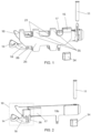
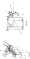
- FIG. 1-13 An embodiment of the system according to the invention is presented in FIG. 1, 2 , 3 and 11 , while FIG. 4 , 5 , 6 and 12 further aid for understanding how the system can be used for picking up and weighing garbage containers.
- FIG. 1 shows a system installable on a garbage truck for weighing a plurality of garbage container types 30, 33, the system comprising: an arm 10b configured for supporting a garbage container 30, 33 of a plurality of types; a pick-up device 10 located at an end of the arm and configured to engage and hold a trunnion 29 of a garbage container of a first pickup type 30; a pick-up comb 25 attached along the arm 10b, or at another end of the arm 10b opposite the end where the pick-up device is located, and configured to engage and hold a lip 32 of a garbage container of a second pickup type 33; at least two load cells 21, 26 of which a first one 26 is connected to the pick-up device 10 and the second one 21 is connected to the pick-up comb 25, wherein the first load cell 26 is configured to measure a weight exerted on the pick-up device 10 when the latter engages the garbage container of the first pickup type 30, and the second load cell 26 is configured to measure a weight exerted on the pick-up comb
- the inclination sensor and the motion sensor are within the electronic device's 17 shown casing which, in that case, defines an electronic unit that comprises the electronic device, the motion sensor and the inclination (tilt) sensor.
- FIG. 1 and 2 can be used for weighing garbage containers 30 whose pickup point is the trunnion 29.
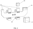
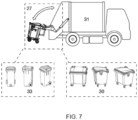
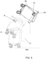
- FIG. 7 , 8 and 9 show a process of lifting the garbage container 30, wherein the container passes through different positions 28a, 28, 26 as it is lifted and rotated by a truck's lifting/collection mechanism 31 to which the system is installed.
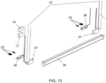
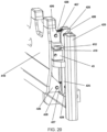
- the arms 10b of a rear-loading garbage truck lifting system are held by means of a base bearing a pin 11 and bushings 13, the bushings 13 allowing for the arm's 10b support and rotation.
- the system shown in FIG. 1 comprises the pick-up device 10, a hook to secure the waste bins (garbage containers) in the system during collection, and a safety mechanism 14 of the pick-up device 10 which is activated during movement and advantageously aids locking the waste bin so that it remains in the lifting system throughout the collection process.
- the pick-up device 10 is a mechanical system which comprises a trigger 18 so that it can touch the bucket throughout the lifting.
- the trigger 18 cooperates with a pivot pin 12 and a bearing with sealing rings 16 in order to transfer forces from the contact with the bucket to the first load cell 26.
- the force is transferred to the load cell 26 through load cell contact 20.
- the placement of the load cell 26 is in such a preferred way as to advantageously always ensure a correct measurement of applied force.
- an RFID reader 34 applied to a suitable point of the lifting system provides identification of the bin (garbage container), when the point of contact of the bin is the grab 10 of the pick-up arm 10b.
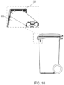
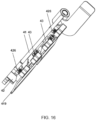
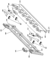
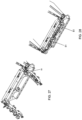
- the collection arm 10b can additionally carry on it the collection comb 25 (pick-up comb) which has the purpose of weighing bins whose point of contact with the lifting mechanism of the garbage truck is their lip 32 as the one shown in FIG. 10 .
- the collection comb 25 pick-up comb
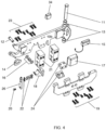
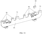
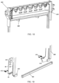
- FIG. 4 , 6 and 12 on the pick-up arm 10b there are mounted two comb load cells (second load cells) 21 with support screws 23 and on the other side the pick-up comb 25 which in turn is screwed with support screws 19 which are according to the specific specifications of the respective load cell manufacturer.
- the shown comb 25 includes three pick-up teeth 35 spaced to specifications to work with buckets (garbage containers) which are according to European or other specifications.
- the comb 25 additionally has a fourth tooth position specially designed to accept an RFID identification reader 15 to provide bin identification.
- a system which can be called load cell overload system or load cell distortion limiter 24, for limiting the torsion or distortion of the load cells, which, due to its design, allows the system to be used without affecting it, and can, in conditions of excessive distortion due to the heavy weight which is outside the specifications of the load cells, to stop the load cells' distortion in order to prevent the possibility of their rupture.
- the system advantageously provides additional safety, for example in the event of rupture or destruction of the load cells the comb can remain in place, preventing accidents without interrupting the operation of the garbage collection.
- the configuration for weighing (measurement of weight) on the comb 25 of the shown embodiments can act as an autonomous weighing system regardless of its position in the lifting system of the rear-loading garbage truck on which the system according to the first aspect of the invention can be installed.
- the weighing on the comb 25 may work in parallel and independently of the weighing on the grab 10 of the harvesting arm 10b.
- the system according to the invention may be autonomous and independent from the lifting system 31 of the garbage truck, may have no common characteristics with existing weighing systems, and may be such that it can be placed in any rear loading lifting system.
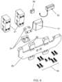
- the system comprises also a lower push/rotate bar 36 which can push the container for turning it over during the collection process, and on the lower push/rotate bar 36 at one or more suitable points, there are installed and appropriately supported one or more additional load cells 38 with distortion limiter(s) 37.
- an electronic data processing device 17 which can also be called or be a part of an electronic unit.
- the electronic device 17 can include one or more sensors for recording the pickup movement consisting of an inertial unit, either an accelerometer, a gyroscope, an inclinometer, or a magnetometer, or another for the for this purpose sensor, inclination sensor of the rear loading garbage truck 31 and typically has a processor, storage memory, wireless communication system and power supply system.
- the readings of each comb load cell 21, grab load cell 26, lower push/swing bar load cell 36 and sensors included or connected to the electronic data processing device/unit 17, may be taken together to measure the bucket weight and the weight of the contents of the bin. This data can be recorded, averaged and/or calculated in the data processing device (unit) 17 and sent wirelessly.
- the electronic data processing and sending device 17 can be interconnected or include within its housing an RFID reader or other wireless or optical means of unique identification of the bins, satellite GNSS positioning, tachograph data reception and CAN bus data reception or OBD.
- a preferred embodiment of a method for weighing using the system according to the invention is as follows. For the accurate weighing of the container (bucket), there are performed a series of mechanical movements and measurements of sensors installed in/with the electronic data processing device 17.
- the system according to a first aspect of the invention is automatically activated by placing the pickup center of gravity pin (trunnion) 29 of the bucket 30 on the aforementioned optional trigger 18 of the system, or placing the bucket lip 32 of the bucket 33 on the pickup comb 25 without the need for intervention of any operator or electronic switch.
- the electronic device or central unit 17 takes continuous weighing measurements (i.e. weight measurement) where at specific times and through the positions between the points A and B shown in FIG. 9 , and in relation to the position and the specific lifting angle, it gives the final highly accurate weighing result.
- the system's components can enable absolute measurement without interference from the rest of the mechanism of the waste lifting system.
- the combination of the arm 10b with the pick-up device 10 and the autonomous comb 25, the pick-up device preferably comprising the trigger 18, can enable accurate measurements when the system is in contact with the waste bin.
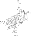
- a load cell arrangement is installed on the arm bases 41.
- a pick-up device (gripper) 42 and through the gripper pin 44, the gripper bushing 45 and the gripper washers 46, which ensure good rotation of the gripper (pickup device) 42 without considerable resistance, the pick-up device can follow a circular motion and come into contact at an appropriate point through a load cell contact 411 with a load cell 43, which is supported on a specially designed base - limiter of distortion (distortion limiter) 418 by means of load cell washers 410 and load cell support screws 412.
- the bucket pin 422 the trunnion of the garbage container
- FIG. 14-17 can be installed on a vehicle 431 by replacing an existing arm of the vehicle, through the arm pin 415 (see FIG. 17 and 23 ) which moves through the arm bearings 47.
- the pick-up comb 419 to which the lip of the bucket (garbage container) is fixed during removal, is supported by a mobile mechanism of heavy-duty multi-point chain links 427 advantageously enabling always carrying the bucket load in a direction perpendicular to the load cell 43.
- Heavy-duty chain anchors 426 are attached to both ends of the multi-point heavy-duty chain 427 with chain pins (links) 428.
- load cells 43 are attached to the base of the arm 41 or to pick-up mechanism 420, and said load cells 43 are supported on a specially designed base - distortion limiter 418 by means of load cell washers 410 and load cell support screws 12, which are independent of the bucket lip gripper 419, through special load cell contacts 411 that advantageously ensure that the movement and load will be transferred to the load cell 43.
- the bottom of the bucket lip gripper (pick-up comb) 419 holds the bucket (garbage container) off the lower push/rotate bar 423) (see FIG. 19 ) during the initial bucket removal (collection) stage.
- a load cell assembly 43 is installed on the lower push/rotate bar 423 of the bucket.
- one or more load cells 43 are installed which are supported in a desired way on the bar.
- each load cell 43 that is connected to the bar is attached to the extraction mechanism 420 either with suitable support screws 412 or in any other suitable way, and is equipped with a distortion limiter 418.
- the aforementioned load cell contacts 411 can be a metal plate, a specially shaped screw or other suitable component, so that, advantageously, it rests on the load cell without being affected by different load directions other than the direction of the measured weight.
- the aforementioned heavy duty chain anchors 426 can be of different sizes and types as shown in FIG. 14 , 16 (one type) and FIG. 20 , 21 (different type).
- the arm grabber (pick-up device) 42 or bin lip grabber (pick-up comb) 419 mechanisms can work independently of the load cells 43, thereby giving the system the ability to operate safely and carry out removals of containers in the event of a problem, damage, rupture or even removal of the load cells 43.
- the pickup device and/or the pick-up comb are configured to engage and support or lift the garbage container independently of whether the respective first and/or load cell is damaged, ruptured or removed from the system.
- all load cells 43 arrangements have a cable 49 protected by a protective tube 48 and possibly (depending on the vehicle) a cover 414 which is fixed with cover support screws 413 (see FIG. 17 ) and adjusted on it in an appropriate way in order to advantageously protect the system and its electronic parts from pressure, washing, shocks or any other external influencing factor, also advantageously, contributing to providing correct operation.
- a cover 414 which is fixed with cover support screws 413 (see FIG. 17 ) and adjusted on it in an appropriate way in order to advantageously protect the system and its electronic parts from pressure, washing, shocks or any other external influencing factor, also advantageously, contributing to providing correct operation.
- one or more sensors 416 are installed to record the pick-up movement (see FIG.
- a tilt sensor (inclination sensor) 425 of the bin collection vehicle is installed at a suitable point on the bin collection vehicle (see FIG. 22 ) or is attached to or integrated in a component, e.g. a mechanical or electronic component, of the system of the first aspect of the invention.
- the measurements from the load cells 43, the inclination sensor 425 and the motion sensor 416 are recorded in an electronic device 417 for processing and sending the data, and the electronic device 417 has a processor, memory storage, wireless communication system and power supply system.
- the readings from the load cells 43, the vehicle inclination sensor 425 and the sensors 416 for recording the collection movement are taken into account to measure the weight of the bin (garbage container) and the weight of the contents of the bin.
- the data is recorded, averaged and/or calculated in the data processing and sending device 417, and sent wirelessly.
- the push/rotate bar 423 of the bucket has supports where friction limiting wheels 421 (see FIG. 22 ) of suitable material are placed to reduce the friction of the contact of the bucket with the push/swivel bar 423.
- the electronic device 417 for processing and sending the data is interconnected or includes within a housing of it an RFID reader or other wireless or optical means of unique identification of the bins, satellite GNSS positioning, receiving tachograph data, receiving CAN bus data or OBD.
- the pick-up motion recording sensor 416, the electronic data processing and sending device 417 and the vehicle inclination sensor 425 are integrated into one device or electronic unit.
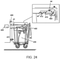
- the system's comb 25 has a tooth, also called RFID tooth 51, wherein an RFID reader is integrated.
- the range 52 of the RFID reader's antenna is such that it covers the position of an RFID tag 53 that preferably is attached to or is integrated in the garbage container (bin) 30. Said range 52 in FIG.25 is indicated by the dashed lines.
- the RFID reader of the embodiment shown in FIG. 25 and 26 has two antennas directed at different directions with respect to each other. The first antenna is directed towards a first direction towards the RFID tag 53 of the bin 30, so that the RFID reader can read the tag when the system engages the trunnion 29 of the container via the system's pick-up device, as shown in FIG.
- the second antenna is directed towards a second direction, which can be substantially normal to the first one, so that it is directed and can read said tag 53 when the system engages the lip of the bin 30 via the comb, as is shown in FIG. 26 .
- the system of FIG. 25 and 26 has two arms each of which having a pick-up device and a comb, as shown in FIG. 27 and 28 wherein the garbage container has been omitted. Each of the arms also has a respective RFID tooth, wherein the RFID reader is integrated in an electronic unit comprising the required electronic components such as the device for processing and transmitting data and an inertial measurement unit (IMU) which is configured (i.e. has the appropriate sensors) to sense/detect motion and tilt (inclination).
- IMU inertial measurement unit
- the system can engage the trunnions of the garbage container via the two system's (one system in each arm) pickup devices.
- the system can engage the lip of the garbage container via the two systems' (one system in each arm) pick-up combs.
- FIG. 29 schematically shows some components of an embodiment of an electronic unit 61 installable on a system, preferably or in a comb's tooth, the unit comprising an electronic device 417 configured for processing and transmitting data, an inertial measurement unit 440 which comprises an inclination sensor 425 and a motion sensor 416, and an RFID reader 441 which comprises two antennas 442, 443, a battery acting as a power source 444 of the unit, and an electronic interface 445 for operationally communicating or controlling the load cells.
- an electronic device 417 configured for processing and transmitting data
- an inertial measurement unit 440 which comprises an inclination sensor 425 and a motion sensor 416
- an RFID reader 441 which comprises two antennas 442, 443, a battery acting as a power source 444 of the unit
- an electronic interface 445 for operationally communicating or controlling the load cells.
Landscapes
- Physics & Mathematics (AREA)
- General Physics & Mathematics (AREA)
- Engineering & Computer Science (AREA)
- Mechanical Engineering (AREA)
- Refuse-Collection Vehicles (AREA)
- Arrangements For Transmission Of Measured Signals (AREA)
Claims (15)
- Auf einem Müllwagen installierbares System zum Wiegen einer Vielzahl von Müllbehältertypen, wobei das System Folgendes umfasst:einen Arm (10b, 41), der dazu konfiguriert ist, einen Müllbehälter (30, 33, 430) einer Vielzahl von Typen zu tragen;eine Aufnahmevorrichtung (10, 42), die sich an einem Ende des Arms befindet und dazu konfiguriert ist, mit einem Zapfen (29, 422) eines Müllbehälters (430, 30, 33) eines ersten Aufnahmetyps in Eingriff zu kommen und diesen zu halten;einen Aufnahmekamm (25, 419), der entlang des Arms (10b, 41) oder an einem anderen Ende des Arms (10b, 41) gegenüber dem Ende, an dem sich die Aufnahmevorrichtung befindet, angebracht ist und dazu konfiguriert ist, mit einer Lippe (32) eines Müllbehälters (430, 30, 33) eines zweiten Aufnahmetyps in Eingriff zu kommen und diese zu halten;mindestens zwei Wägezellen (21, 26, 43), von denen eine erste (26, 43) mit der Aufnahmevorrichtung (10, 42) verbunden ist und die zweite (21, 43) mit dem Aufnahmekamm (25, 419) verbunden ist, wobei die erste Wägezelle (26, 43) dazu konfiguriert ist, ein Gewicht zu messen, das auf die Aufnahmevorrichtung (10, 42) ausgeübt wird, wenn letztere mit dem Müllbehälter (430, 30, 33) des ersten Aufnahmetyps in Eingriff kommt, und die zweite Wägezelle (21, 43) dazu konfiguriert ist, ein Gewicht zu messen, das auf den Aufnahmekamm (25, 419) ausgeübt wird, wenn letzterer mit dem Müllbehälter (430, 30, 33) des zweiten Aufnahmetyps in Eingriff kommt;mindestens einen Bewegungssensor (416), der dazu konfiguriert ist, eine Bewegung im Zusammenhang mit einer Sammlung des Müllbehälters (430, 30, 33) des ersten oder zweiten Aufnahmetyps durch das System aufzuzeichnen;mindestens einen Neigungssensor (425), der dazu konfiguriert ist, eine Neigung eines Müllwagens zu erfassen, wenn das System auf dem Müllwagen (431) installiert ist; mindestens eine elektronische Vorrichtung (417), die dazu konfiguriert ist, Daten zu verarbeiten und zu übertragen; und eine oder mehrere elektronische Einheiten (61), wobei jede elektronische Einheit eine oder mehrere von jeder der mindestens einen elektronischen Vorrichtung (417), des mindestens einen Neigungssensors (425) und des mindestens einen Bewegungssensors (416) umfasst, wobei vorzugsweise jede elektronische Einheit (61) ferner ein RFID-Lesegerät (441) umfasst, das Teil der elektronischen Vorrichtung ist oder betriebsmäßig mit dieser verbunden ist;wobei eine der einen oder mehreren elektronischen Einheiten (61) in den Aufnahmekamm (25, 419), den Arm (10b, 41) oder die Aufnahmevorrichtung (10, 42) integriert ist; und wobei das System vorzugsweise zwei elektronische Einheiten (61) umfasst.
- System nach Anspruch 1, das ferner eine dritte Wägezelle (21, 43) umfasst, die mit dem Aufnahmekamm (25, 419) verbunden ist, wobei die dritte Wägezelle (21, 43) dazu konfiguriert ist, ein Gewicht zu messen, das auf den Aufnahmekamm (25, 419) ausgeübt wird, wenn letzterer mit dem Müllbehälter (430, 30, 33) des zweiten Aufnahmetyps in Eingriff kommt, wobei die dritte Wägezelle (21, 43) sich in einem Abstand von der zweiten Wägezelle (21, 43) befindet, so dass die zweite und die dritte Wägezelle (21, 43) zum Messen der Lastverteilung entlang des Aufnahmekamms (25, 419); und/oder das ferner eine Stange (36, 423) umfasst, die dazu angeordnet und konfiguriert ist, mit dem Müllbehälter (430, 30, 33) des ersten oder zweiten Aufnahmetyps an einem Punkt des Behälters in Kontakt zu kommen und diesen zu schieben, so dass, wenn sich der Müllbehälter (430, 30, 33) in einer Betriebsposition auf einem Boden befindet und mit der Aufnahmevorrichtung (10, 42) oder dem Aufnahmekamm (25, 419) in Eingriff steht, der Punkt des Behälters (430, 30, 33), der mit der Stange (36, 423) in Kontakt steht, in Bezug auf die Kontaktpunkte des Behälters mit der Aufnahmevorrichtung (10, 42) oder dem Aufnahmekamm (25, 419) jeweils tiefer liegt, wobei das System vorzugsweise ferner eine oder mehrere zusätzliche Wägezellen (38, 43) umfasst, die mit der Stange (36, 423) verbunden und dazu konfiguriert sind, ein Gewicht zu messen, das auf die Stange (36, 423) ausgeübt wird, wenn letztere den Müllbehälter schiebt.
- System nach einem der vorhergehenden Ansprüche, wobei die mindestens eine elektronische Vorrichtung (417) betriebsmäßig mit mindestens einem entsprechenden von jedem von dem mindestens einen Bewegungssensor (416), den mindestens zwei Wägezellen (21, 26, 43) und dem mindestens einen Neigungssensor (425) verbunden ist.
- System nach einem der vorhergehenden Ansprüche, das ferner zwei oder mehr Wägezellen-Verzerrungsbegrenzer (24, 37, 418) umfasst, und wobei jede Wägezelle (21, 26, 43, 38) mit einem entsprechenden von den Wägezellen-Verzerrungsbegrenzern (24, 37) verbunden ist, wobei jeder Wägezellen-Verzerrungsbegrenzer (24, 37, 418) dazu konfiguriert ist, die Verzerrung der entsprechenden Wägezelle (21, 26, 38, 43) zu begrenzen, wenn die Verzerrung über einem Schwellenwert liegt, und wobei vorzugsweise jeder der Wägezellen-Verzerrungsbegrenzer (24, 37, 418), der mit einer entsprechenden von den Wägezellen (21, 26, 43, 38) verbunden ist, auch entsprechend mit einem von den Wägezellen, der Aufnahmevorrichtung (10, 42), dem Aufnahmekamm (25, 419) oder der Stange (36, 423), die mit der entsprechenden Wägezelle (21, 26, 43, 38) verbunden ist, verbunden ist, und dazu konfiguriert ist, im Falle eines Ausfalls dieser zu stützen.
- System nach einem der vorhergehenden Ansprüche, wobei der mindestens eine Bewegungssensor (416) einen beliebigen von einer Trägheitsmesseinheit (440), einem Beschleunigungsmesser, einem Gyroskop, einem Neigungsmesser (425), einem Magnetometer oder einem anderen Typ von Sensor umfasst und/oder wobei vorzugsweise der mindestens eine Bewegungssensor einen Beschleunigungsmesser und eine Trägheitsmesseinheit beinhaltet.
- System nach einem der vorhergehenden Ansprüche, wobei das System eine Trägheitsmesseinheit (440) umfasst, die den mindestens einen Bewegungssensor (416) und/oder den mindestens einen Neigungssensor (425) umfasst.
- System nach einem der vorhergehenden Ansprüche, das ferner mindestens ein RFID-Lesegerät (441) umfasst, das Teil der mindestens einen elektronischen Vorrichtung (417) ist oder betriebsmäßig mit dieser verbunden ist, wobei das System vorzugsweise entweder ein RFID-Lesegerät (441), das in einen Zahn (51) des Aufnahmekamms (25, 419) integriert ist, oder zwei RFID-Lesegeräte (441) umfasst, von denen eines in den Zahn (51) des Aufnahmekamms (25, 419) integriert ist und das andere in den Arm (10b, 41) integriert ist, und wobei vorzugsweise das mindestens eine RFID-Lesegerät (441) zwei Antennen (442, 443) umfasst, die in zwei jeweilige Richtungen zeigen, die sich voneinander unterscheiden.
- System nach einem der vorhergehenden Ansprüche, wobei die elektronische Vorrichtung (417) mit einem beliebigen von einem RFID-Lesegerät (441) zur Mülleimeridentifizierung, Mitteln zum Identifizieren von Mülleimern, Mitteln zur GNSS-Satellitenortung, Mitteln zum Herstellen einer Schnittstelle mit einem Fahrtenschreiber und zum Herunterladen von Daten von diesem, Mitteln zum Herstellen einer Schnittstelle mit einem CAN-Bus und zum Herunterladen von Daten von diesem, Mitteln zum Herstellen einer Schnittstelle mit einem On-Board-, OBD-Diagnosesystem und zum Herunterladen von Daten von diesem, einem Kommunikationssystem oder einer Kombination davon verbindbar ist oder diese umfasst, vorzugsweise in einem Gehäuse davon.
- System nach einem der vorhergehenden Ansprüche, wobei eine elektronische Einheit (61) an einem Zahn (51) des Aufnahmekamms (25, 419) vorhanden ist und/oder der Aufnahmekamm (25, 419) in den Arm (10b, 41) integriert oder vorzugsweise abnehmbar am Arm (10b, 41) angebracht ist.
- System nach einem der vorhergehenden Ansprüche, wobei das System ferner eine Basis umfasst, die mit dem Arm (10b, 41) verbunden ist, wobei sich die Basis (10b, 41) und die Aufnahmevorrichtung (10, 42) an gegenüberliegenden Enden des Arms (10b, 41) befinden, wobei die Basis einen Stift (11, 415) und eine Buchse (13, 47) umfasst, die dazu konfiguriert sind, eine Drehung des Arms (10b, 41) zu ermöglichen.
- System nach einem der vorhergehenden Ansprüche, wobei der Aufnahmekamm (25, 419) und der Arm (10b, 41) in Längsrichtung parallel zueinander sind.
- System nach einem der vorhergehenden Ansprüche, das ferner einen Näherungssensor umfasst, wobei der Näherungssensor vorzugsweise ein induktiver Sensor ist und vorzugsweise zu Folgendem konfiguriert ist:(i) Erkennen einer Verriegelung des Müllbehälters durch das System, wobei die Verriegelung das Ausüben von Druck auf den Müllbehälter durch das System umfasst und der Näherungssensor ferner dazu konfiguriert ist, die elektronische Vorrichtung auszulösen, um Gewichtsmessungen während des Verriegelungsvorgangs zu ignorieren oder zu verhindern; oder(ii) Erkennen einer Drehung, eines Schließens oder eines Zurückziehens des Arms in Richtung eines Müllwagens, wenn das System betriebsmäßig auf dem Müllwagen installiert ist, wobei vorzugsweise der Näherungssensor betriebsmäßig mit der elektronischen Vorrichtung (417) verbunden ist.
- System nach einem der vorhergehenden Ansprüche, wobei die Aufnahmevorrichtung (10, 42) einen Auslöser (18) umfasst, der dazu konfiguriert ist, aktiviert zu werden, wenn die Aufnahmevorrichtung (10, 42) mit dem Zapfen (29, 422) in Eingriff kommt, und die elektronische Vorrichtung (417) oder die erste Wägezelle (26, 43) auszulösen.
- System nach einem der vorhergehenden Ansprüche, wobei die elektronische Vorrichtung programmierbar und dazu konfiguriert ist, eine Reihe von Gewichtsmessungen zu überwachen, eine Abweichung innerhalb der Reihe zu identifizieren und entsprechend der Abweichung einige der Gewichtsmessungen der Reihe zu ignorieren.
- Müllwagen, der ein System nach einem der Ansprüche 1-14 umfasst, wobei der Müllwagen vorzugsweise einen Mechanismus (27, 31) umfasst, der dazu konfiguriert ist, Müllbehälter anzuheben, und wobei das System an dem Hebemechanismus (27, 31) installiert ist oder einen Teil davon bildet und/oder wobei das System vorzugsweise an einem Heck des Müllwagens installiert ist.
Priority Applications (1)
| Application Number | Priority Date | Filing Date | Title |
|---|---|---|---|
| HRP20250953TT HRP20250953T1 (hr) | 2021-10-31 | 2022-10-31 | Sustav koji se može ugraditi na kamion za otpad za mjerenje kontejnera za otpad, povezanu uporabu i kamion za otpad |
Applications Claiming Priority (3)
| Application Number | Priority Date | Filing Date | Title |
|---|---|---|---|
| GR20210100754A GR1010566B (el) | 2021-10-31 | 2021-10-31 | Συστημα μετρησης βαρους καδων αποκομιδης ενσωματωμενο στο μηχανισμο αποκομιδης οχηματων |
| GR20220100444A GR20220100444A (el) | 2022-05-27 | 2022-05-27 | Συστημα διαδικτυου των αντικειμενων (ιοτ) μετρησης βαρους καδων αποκομιδης προς προσαρμογη σε ανυψωτικους μηχανισμους οχηματων οπισθιας φορτωσης με περιορισμο στρεβλωσης δυναμοκυψελων |
| PCT/EP2022/080368 WO2023073230A1 (en) | 2021-10-31 | 2022-10-31 | A system installable on a garbage truck for weighing garbage containers, a related use and a garbage truck |
Publications (3)
| Publication Number | Publication Date |
|---|---|
| EP4381256A1 EP4381256A1 (de) | 2024-06-12 |
| EP4381256C0 EP4381256C0 (de) | 2025-05-07 |
| EP4381256B1 true EP4381256B1 (de) | 2025-05-07 |
Family
ID=84362062
Family Applications (1)
| Application Number | Title | Priority Date | Filing Date |
|---|---|---|---|
| EP22812576.1A Active EP4381256B1 (de) | 2021-10-31 | 2022-10-31 | Auf einem müllwagen installierbares system zum wiegen von müllbehältern, zugehörige verwendung und müllwagen |
Country Status (6)
| Country | Link |
|---|---|
| EP (1) | EP4381256B1 (de) |
| ES (1) | ES3037644T3 (de) |
| HR (1) | HRP20250953T1 (de) |
| HU (1) | HUE072308T2 (de) |
| PL (1) | PL4381256T3 (de) |
| WO (1) | WO2023073230A1 (de) |
Families Citing this family (1)
| Publication number | Priority date | Publication date | Assignee | Title |
|---|---|---|---|---|
| US12540030B2 (en) * | 2023-11-21 | 2026-02-03 | Perkins Manufacturing Co. | Container washer lifter for rear load vehicle |
Family Cites Families (2)
| Publication number | Priority date | Publication date | Assignee | Title |
|---|---|---|---|---|
| DE3405997C2 (de) * | 1984-02-20 | 1987-01-08 | Zöller-Kipper GmbH, 6500 Mainz | Vorrichtung zum Entleeren von Behältern, insbesondere von Müllbehältern in Sammelbehälter |
| JP3779140B2 (ja) * | 2000-09-05 | 2006-05-24 | 極東開発工業株式会社 | 塵芥収集車の塵芥投入装置 |
-
2022
- 2022-10-31 PL PL22812576.1T patent/PL4381256T3/pl unknown
- 2022-10-31 WO PCT/EP2022/080368 patent/WO2023073230A1/en not_active Ceased
- 2022-10-31 EP EP22812576.1A patent/EP4381256B1/de active Active
- 2022-10-31 ES ES22812576T patent/ES3037644T3/es active Active
- 2022-10-31 HU HUE22812576A patent/HUE072308T2/hu unknown
- 2022-10-31 HR HRP20250953TT patent/HRP20250953T1/hr unknown
Also Published As
| Publication number | Publication date |
|---|---|
| PL4381256T3 (pl) | 2025-09-22 |
| EP4381256A1 (de) | 2024-06-12 |
| WO2023073230A1 (en) | 2023-05-04 |
| HRP20250953T1 (hr) | 2025-10-10 |
| HUE072308T2 (hu) | 2025-11-28 |
| EP4381256C0 (de) | 2025-05-07 |
| ES3037644T3 (en) | 2025-10-03 |
Similar Documents
| Publication | Publication Date | Title |
|---|---|---|
| CA2798525C (en) | Load-measuring, fleet asset tracking and data management system for load-lifting vehicles | |
| EP0535339B1 (de) | Lastmomentanzeigevorrichtung | |
| US20210078799A1 (en) | Refuse Vehicle Dump Verification System and Apparatus | |
| EP4381256B1 (de) | Auf einem müllwagen installierbares system zum wiegen von müllbehältern, zugehörige verwendung und müllwagen | |
| JPH0572023A (ja) | 荷重の運転中に荷重の重量を決定するための計量装置およびその方法 | |
| JPS61215923A (ja) | 容器から集収車へ空けられる材料の重量検出法と装置 | |
| CN102735318A (zh) | 用于物料传送车辆的测量系统 | |
| US5215155A (en) | Weighing device for containers to be moved by an arm system | |
| US6486787B2 (en) | Heavy goods vehicle with an overload security device | |
| EP2305578A1 (de) | Vorrichtung zum Sammeln von Müll, wie beispielsweise ein Müllsammelfahrzeug | |
| EP3409635A1 (de) | Wiegesystem für eine hebevorrichtung | |
| AU2022206697A1 (en) | Container rotator with improved side wall support | |
| GB2454993A (en) | Load cell unit having a planar antenna | |
| GR1010239B (el) | Συστημα μετρησης βαρους καδων αποκομιδης ενσωματωμενο στο μηχανισμο αποκομιδης οχηματων | |
| JPH07209063A (ja) | 廃物収集作業車 | |
| JP3171521B2 (ja) | 廃物収集装置の安全装置 | |
| JPH0459572B2 (de) | ||
| GR1010566B (el) | Συστημα μετρησης βαρους καδων αποκομιδης ενσωματωμενο στο μηχανισμο αποκομιδης οχηματων | |
| GR20220100444A (el) | Συστημα διαδικτυου των αντικειμενων (ιοτ) μετρησης βαρους καδων αποκομιδης προς προσαρμογη σε ανυψωτικους μηχανισμους οχηματων οπισθιας φορτωσης με περιορισμο στρεβλωσης δυναμοκυψελων | |
| GB2064794A (en) | Weighing apparatus | |
| JP2003176002A (ja) | 回収箱からの所定物品収集装置およびその収集方法 | |
| JP3102617B2 (ja) | 廃物収集作業車 | |
| GB2368438A (en) | Data acquisition systems | |
| CN111874492A (zh) | 车载称重传感器 | |
| JP3606849B2 (ja) | 大型運搬車両 |
Legal Events
| Date | Code | Title | Description |
|---|---|---|---|
| REG | Reference to a national code |
Ref country code: HR Ref legal event code: TUEP Ref document number: P20250953T Country of ref document: HR |
|
| STAA | Information on the status of an ep patent application or granted ep patent |
Free format text: STATUS: UNKNOWN |
|
| STAA | Information on the status of an ep patent application or granted ep patent |
Free format text: STATUS: THE INTERNATIONAL PUBLICATION HAS BEEN MADE |
|
| PUAI | Public reference made under article 153(3) epc to a published international application that has entered the european phase |
Free format text: ORIGINAL CODE: 0009012 |
|
| STAA | Information on the status of an ep patent application or granted ep patent |
Free format text: STATUS: REQUEST FOR EXAMINATION WAS MADE |
|
| 17P | Request for examination filed |
Effective date: 20240304 |
|
| AK | Designated contracting states |
Kind code of ref document: A1 Designated state(s): AL AT BE BG CH CY CZ DE DK EE ES FI FR GB GR HR HU IE IS IT LI LT LU LV MC ME MK MT NL NO PL PT RO RS SE SI SK SM TR |
|
| GRAP | Despatch of communication of intention to grant a patent |
Free format text: ORIGINAL CODE: EPIDOSNIGR1 |
|
| STAA | Information on the status of an ep patent application or granted ep patent |
Free format text: STATUS: GRANT OF PATENT IS INTENDED |
|
| RIC1 | Information provided on ipc code assigned before grant |
Ipc: B65F 3/02 20060101ALI20241126BHEP Ipc: B65F 3/04 20060101ALI20241126BHEP Ipc: G01G 19/08 20060101AFI20241126BHEP |
|
| DAV | Request for validation of the european patent (deleted) | ||
| DAX | Request for extension of the european patent (deleted) | ||
| INTG | Intention to grant announced |
Effective date: 20241205 |
|
| GRAS | Grant fee paid |
Free format text: ORIGINAL CODE: EPIDOSNIGR3 |
|
| GRAA | (expected) grant |
Free format text: ORIGINAL CODE: 0009210 |
|
| STAA | Information on the status of an ep patent application or granted ep patent |
Free format text: STATUS: THE PATENT HAS BEEN GRANTED |
|
| AK | Designated contracting states |
Kind code of ref document: B1 Designated state(s): AL AT BE BG CH CY CZ DE DK EE ES FI FR GB GR HR HU IE IS IT LI LT LU LV MC ME MK MT NL NO PL PT RO RS SE SI SK SM TR |
|
| REG | Reference to a national code |
Ref country code: GB Ref legal event code: FG4D |
|
| REG | Reference to a national code |
Ref country code: CH Ref legal event code: EP |
|
| REG | Reference to a national code |
Ref country code: DE Ref legal event code: R096 Ref document number: 602022014448 Country of ref document: DE |
|
| REG | Reference to a national code |
Ref country code: IE Ref legal event code: FG4D |
|
| U01 | Request for unitary effect filed |
Effective date: 20250606 |
|
| U07 | Unitary effect registered |
Designated state(s): AT BE BG DE DK EE FI FR IT LT LU LV MT NL PT RO SE SI Effective date: 20250616 |
|
| REG | Reference to a national code |
Ref country code: ES Ref legal event code: FG2A Ref document number: 3037644 Country of ref document: ES Kind code of ref document: T3 Effective date: 20251003 |
|
| REG | Reference to a national code |
Ref country code: HR Ref legal event code: T1PR Ref document number: P20250953 Country of ref document: HR |
|
| PG25 | Lapsed in a contracting state [announced via postgrant information from national office to epo] |
Ref country code: RS Free format text: LAPSE BECAUSE OF FAILURE TO SUBMIT A TRANSLATION OF THE DESCRIPTION OR TO PAY THE FEE WITHIN THE PRESCRIBED TIME-LIMIT Effective date: 20250807 |
|
| PG25 | Lapsed in a contracting state [announced via postgrant information from national office to epo] |
Ref country code: IS Free format text: LAPSE BECAUSE OF FAILURE TO SUBMIT A TRANSLATION OF THE DESCRIPTION OR TO PAY THE FEE WITHIN THE PRESCRIBED TIME-LIMIT Effective date: 20250907 |
|
| REG | Reference to a national code |
Ref country code: GR Ref legal event code: EP Ref document number: 20250401580 Country of ref document: GR Effective date: 20251009 |
|
| REG | Reference to a national code |
Ref country code: CH Ref legal event code: U11 Free format text: ST27 STATUS EVENT CODE: U-0-0-U10-U11 (AS PROVIDED BY THE NATIONAL OFFICE) Effective date: 20251101 |
|
| REG | Reference to a national code |
Ref country code: HU Ref legal event code: AG4A Ref document number: E072308 Country of ref document: HU |
|
| U20 | Renewal fee for the european patent with unitary effect paid |
Year of fee payment: 4 Effective date: 20251027 |
|
| REG | Reference to a national code |
Ref country code: HR Ref legal event code: ODRP Ref document number: P20250953 Country of ref document: HR Payment date: 20251031 Year of fee payment: 4 |
|
| PGFP | Annual fee paid to national office [announced via postgrant information from national office to epo] |
Ref country code: HU Payment date: 20251107 Year of fee payment: 4 |
|
| PGFP | Annual fee paid to national office [announced via postgrant information from national office to epo] |
Ref country code: NO Payment date: 20251029 Year of fee payment: 4 |
|
| PG25 | Lapsed in a contracting state [announced via postgrant information from national office to epo] |
Ref country code: SM Free format text: LAPSE BECAUSE OF FAILURE TO SUBMIT A TRANSLATION OF THE DESCRIPTION OR TO PAY THE FEE WITHIN THE PRESCRIBED TIME-LIMIT Effective date: 20250507 |
|
| PGFP | Annual fee paid to national office [announced via postgrant information from national office to epo] |
Ref country code: HR Payment date: 20251031 Year of fee payment: 4 |
|
| PGFP | Annual fee paid to national office [announced via postgrant information from national office to epo] |
Ref country code: GR Payment date: 20251031 Year of fee payment: 4 |
|
| PGFP | Annual fee paid to national office [announced via postgrant information from national office to epo] |
Ref country code: CH Payment date: 20251101 Year of fee payment: 4 |
|
| PGFP | Annual fee paid to national office [announced via postgrant information from national office to epo] |
Ref country code: CZ Payment date: 20251103 Year of fee payment: 4 |
|
| PGFP | Annual fee paid to national office [announced via postgrant information from national office to epo] |
Ref country code: PL Payment date: 20251031 Year of fee payment: 4 |
|
| PG25 | Lapsed in a contracting state [announced via postgrant information from national office to epo] |
Ref country code: SK Free format text: LAPSE BECAUSE OF FAILURE TO SUBMIT A TRANSLATION OF THE DESCRIPTION OR TO PAY THE FEE WITHIN THE PRESCRIBED TIME-LIMIT Effective date: 20250507 |
|
| PGFP | Annual fee paid to national office [announced via postgrant information from national office to epo] |
Ref country code: ES Payment date: 20251112 Year of fee payment: 4 |