EP4375682A1 - Verfahren zur erkennung der frequenz eines stromnetzes, vorrichtung, verfahren zur einstellung der frequenz eines stromnetzes und vorrichtung - Google Patents
Verfahren zur erkennung der frequenz eines stromnetzes, vorrichtung, verfahren zur einstellung der frequenz eines stromnetzes und vorrichtung Download PDFInfo
- Publication number
- EP4375682A1 EP4375682A1 EP22871530.6A EP22871530A EP4375682A1 EP 4375682 A1 EP4375682 A1 EP 4375682A1 EP 22871530 A EP22871530 A EP 22871530A EP 4375682 A1 EP4375682 A1 EP 4375682A1
- Authority
- EP
- European Patent Office
- Prior art keywords
- power grid
- grid frequency
- voltage
- frequency
- decoupled
- Prior art date
- Legal status (The legal status is an assumption and is not a legal conclusion. Google has not performed a legal analysis and makes no representation as to the accuracy of the status listed.)
- Pending
Links
Images


Classifications
-
- H—ELECTRICITY
- H02—GENERATION; CONVERSION OR DISTRIBUTION OF ELECTRIC POWER
- H02J—ELECTRIC POWER NETWORKS; CIRCUIT ARRANGEMENTS OR SYSTEMS FOR SUPPLYING OR DISTRIBUTING ELECTRIC POWER; SYSTEMS FOR STORING ELECTRIC ENERGY
- H02J3/00—Circuit arrangements for AC mains or AC distribution networks
- H02J3/38—Arrangements for feeding a single network from two or more generators or sources in parallel; Arrangements for feeding already energised networks from additional generators or sources in parallel
- H02J3/46—Controlling the sharing of generated power between the generators, sources or networks
- H02J3/48—Controlling the sharing of active power
-
- G—PHYSICS
- G01—MEASURING; TESTING
- G01R—MEASURING ELECTRIC VARIABLES; MEASURING MAGNETIC VARIABLES
- G01R19/00—Arrangements for measuring currents or voltages or for indicating presence or sign thereof
- G01R19/25—Arrangements for measuring currents or voltages or for indicating presence or sign thereof using digital measurement techniques
- G01R19/2513—Arrangements for monitoring electric power systems, e.g. power lines or loads; Logging
-
- G—PHYSICS
- G01—MEASURING; TESTING
- G01R—MEASURING ELECTRIC VARIABLES; MEASURING MAGNETIC VARIABLES
- G01R21/00—Arrangements for measuring electric power or power factor
- G01R21/001—Measuring real or reactive component; Measuring apparent energy
- G01R21/002—Measuring real component
-
- G—PHYSICS
- G01—MEASURING; TESTING
- G01R—MEASURING ELECTRIC VARIABLES; MEASURING MAGNETIC VARIABLES
- G01R23/00—Arrangements for measuring frequencies; Arrangements for analysing frequency spectra
- G01R23/02—Arrangements for measuring frequency, e.g. pulse repetition rate; Arrangements for measuring period of current or voltage
-
- G—PHYSICS
- G01—MEASURING; TESTING
- G01R—MEASURING ELECTRIC VARIABLES; MEASURING MAGNETIC VARIABLES
- G01R23/00—Arrangements for measuring frequencies; Arrangements for analysing frequency spectra
- G01R23/16—Spectrum analysis; Fourier analysis
- G01R23/165—Spectrum analysis; Fourier analysis using filters
-
- G—PHYSICS
- G01—MEASURING; TESTING
- G01R—MEASURING ELECTRIC VARIABLES; MEASURING MAGNETIC VARIABLES
- G01R25/00—Arrangements for measuring phase angle between a voltage and a current or between voltages or currents
-
- G—PHYSICS
- G01—MEASURING; TESTING
- G01R—MEASURING ELECTRIC VARIABLES; MEASURING MAGNETIC VARIABLES
- G01R31/00—Arrangements for testing electric properties; Arrangements for locating electric faults; Arrangements for electrical testing characterised by what is being tested not provided for elsewhere
- G01R31/34—Testing dynamo-electric machines
-
- H—ELECTRICITY
- H02—GENERATION; CONVERSION OR DISTRIBUTION OF ELECTRIC POWER
- H02J—ELECTRIC POWER NETWORKS; CIRCUIT ARRANGEMENTS OR SYSTEMS FOR SUPPLYING OR DISTRIBUTING ELECTRIC POWER; SYSTEMS FOR STORING ELECTRIC ENERGY
- H02J3/00—Circuit arrangements for AC mains or AC distribution networks
- H02J3/001—Arrangements for handling faults or abnormalities, e.g. emergencies or contingencies
- H02J3/0014—Arrangements for handling faults or abnormalities, e.g. emergencies or contingencies for preventing or reducing power oscillations in networks
- H02J3/00142—Oscillations concerning frequency
-
- H—ELECTRICITY
- H02—GENERATION; CONVERSION OR DISTRIBUTION OF ELECTRIC POWER
- H02J—ELECTRIC POWER NETWORKS; CIRCUIT ARRANGEMENTS OR SYSTEMS FOR SUPPLYING OR DISTRIBUTING ELECTRIC POWER; SYSTEMS FOR STORING ELECTRIC ENERGY
- H02J3/00—Circuit arrangements for AC mains or AC distribution networks
- H02J3/38—Arrangements for feeding a single network from two or more generators or sources in parallel; Arrangements for feeding already energised networks from additional generators or sources in parallel
- H02J3/381—Dispersed generators
-
- H—ELECTRICITY
- H02—GENERATION; CONVERSION OR DISTRIBUTION OF ELECTRIC POWER
- H02J—ELECTRIC POWER NETWORKS; CIRCUIT ARRANGEMENTS OR SYSTEMS FOR SUPPLYING OR DISTRIBUTING ELECTRIC POWER; SYSTEMS FOR STORING ELECTRIC ENERGY
- H02J2101/00—Supply or distribution of decentralised, dispersed or local electric power generation
- H02J2101/20—Dispersed power generation using renewable energy sources
- H02J2101/28—Wind energy
-
- Y—GENERAL TAGGING OF NEW TECHNOLOGICAL DEVELOPMENTS; GENERAL TAGGING OF CROSS-SECTIONAL TECHNOLOGIES SPANNING OVER SEVERAL SECTIONS OF THE IPC; TECHNICAL SUBJECTS COVERED BY FORMER USPC CROSS-REFERENCE ART COLLECTIONS [XRACs] AND DIGESTS
- Y02—TECHNOLOGIES OR APPLICATIONS FOR MITIGATION OR ADAPTATION AGAINST CLIMATE CHANGE
- Y02E—REDUCTION OF GREENHOUSE GAS [GHG] EMISSIONS, RELATED TO ENERGY GENERATION, TRANSMISSION OR DISTRIBUTION
- Y02E10/00—Energy generation through renewable energy sources
- Y02E10/70—Wind energy
- Y02E10/72—Wind turbines with rotation axis in wind direction
-
- Y—GENERAL TAGGING OF NEW TECHNOLOGICAL DEVELOPMENTS; GENERAL TAGGING OF CROSS-SECTIONAL TECHNOLOGIES SPANNING OVER SEVERAL SECTIONS OF THE IPC; TECHNICAL SUBJECTS COVERED BY FORMER USPC CROSS-REFERENCE ART COLLECTIONS [XRACs] AND DIGESTS
- Y02—TECHNOLOGIES OR APPLICATIONS FOR MITIGATION OR ADAPTATION AGAINST CLIMATE CHANGE
- Y02E—REDUCTION OF GREENHOUSE GAS [GHG] EMISSIONS, RELATED TO ENERGY GENERATION, TRANSMISSION OR DISTRIBUTION
- Y02E10/00—Energy generation through renewable energy sources
- Y02E10/70—Wind energy
- Y02E10/76—Power conversion electric or electronic aspects
Definitions
- the present disclosure generally relates to the field of power technology, and in particular to a method and apparatus for detecting a power grid frequency, and a method and apparatus for regulating a power grid frequency.
- inertia response and primary frequency regulation are required for connecting a wind farm to a power grid.
- a large wind turbine is connected to the power grid through an inverter, and has an advantages of flexible control and fast response as compared to a synchronous generator (e.g., generators for thermal power and a hydropower) for the traditional power grid.
- a method for the wind turbine to participate in inertia support and power grid frequency regulation mainly includes a method for controlling kinetic energy of a rotor and a method for controlling a standby power. Detecting the power grid frequency with high-precision is a foundation for achieving inertia response and primary frequency regulation.
- Embodiments of the present disclosure are to provide a method and an apparatus for detecting a power grid frequency and a method and an apparatus for regulating a power grid frequency that can conveniently, quickly, and accurately detect the power grid frequency and effectively regulate the power grid frequency.
- a method for detecting a power grid frequency includes: converting a collected three-phase voltage at a point of common coupling into a two-phase voltage; transforming the two-phase voltage based on a phase angle of a specific frequency to obtain a positive sequence component to be decoupled and a voltage negative sequence component to be decoupled; decoupling the voltage positive sequence component to be decoupled and the voltage negative sequence component to be decoupled based on the phase angle, and filtering a decoupled voltage positive sequence component to obtain a voltage positive sequence fundamental component; performing inverse transformation on the voltage positive sequence fundamental component based on the phase angle to obtain a set of orthogonal voltage components in a two-phase stationary coordinate system; obtaining a phase angle of a power grid based on the set of orthogonal voltage components; and obtaining a power grid frequency based on the phase angle of the power grid.
- a method for regulating a power grid frequency includes: determining whether there is a disturbance in an amplitude of a three-phase voltage at a point of common coupling; determining whether a response condition for power grid frequency regulation is met based on a detected power grid frequency and/or a change rate of the power grid frequency when there is no disturbance; controlling a power of a wind turbine based on the power grid frequency and/or the change rate of the power grid frequency to regulate the power grid frequency when the response condition for power grid frequency regulation is met; and where the power grid frequency and/or the change rate of the power grid frequency are obtained by performing the method for detecting a power grid frequency as described above.
- an apparatus for detecting a power grid frequency includes: a two-phase voltage acquisition unit configured to convert a collected three-phase voltage at a point of common coupling into a two-phase voltage; a transformation unit configured to transform the two-phase voltage based on a phase angle of a specific frequency to obtain a voltage positive sequence component to be decoupled and a voltage negative sequence component to be decoupled; a decoupling and filtering unit configured to decouple the voltage positive sequence component to be decoupled and the voltage negative sequence component to be decoupled based on the phase angle, and to filter a decoupled voltage positive sequence component to obtain a voltage positive sequence fundamental component; an inverse transformation unit configured to perform inverse transformation on the voltage positive sequence fundamental component based on the phase angle to obtain a set of orthogonal voltage components in a two-phase stationary coordinate system; a power grid phase angle acquisition unit configured to obtain a phase angle of the power grid based on the set of orthogonal voltage components;
- an apparatus for regulating a power grid frequency includes: a voltage disturbance determination unit configured to determine whether there is a disturbance in an amplitude of a three-phase voltage at a point of common coupling; a response condition determination unit configured to determine whether a response condition for power grid frequency regulation is met based on a detected power grid frequency and/or a change rate of the power grid frequency when there is no disturbance; a power grid frequency regulation unit configured to control a power of a wind turbine based on the grid frequency and/or the change rate of the power grid frequency to regulate the power grid frequency when the response condition for power grid frequency regulation is met; and where the power grid frequency and/or the change rate of the power grid frequency are obtained through the apparatus for detecting a power grid frequency as described above.
- a computer-readable storage medium storing a computer program.
- the computer program when executed by a processor, causes the processor to perform the method for detecting a power grid frequency as described above and/or the method for regulating a power grid frequency as described above.
- an electronic device includes: a processor; a memory, storing a computer program, where the computer program, when executed by the processor, causes the processor to perform the method for detecting a power grid frequency as described above and/or the method for regulating a power grid frequency as described above.
- the power grid frequency and the change rate thereof can be detected with high-precision and high response speed, so that the detection accuracy of the power grid frequency and the change rate thereof meets the required technical indicators, and the time for detecting the power grid frequency and the change rate thereof becomes short. Moreover, it has a good power grid imbalance adaptability, harmonics adaptability, voltage offset adaptability, and frequency offset adaptability .
- the method for detecting a power grid frequency and the method for regulating a power grid frequency according to the present disclosure can be implemented without adding additional hardware to the wind turbine, thereby achieving rapid development, application of new models, and on-site modification.
- the active power increment is calculate based on the detected power grid frequency and the change rate thereof in combination with the virtual inertia equation, and the active power increment is converted into a motor control torque command to complete power control, and thus achieve the inertia response and primary frequency regulation of the wind turbine.
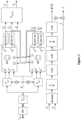
- Figure 1 shows a flowchart of a method for detecting a power grid frequency according to an embodiment of the present disclosure.
- the method for detecting a power grid frequency can be performed by a converter (such as a controller of the converter) of a wind turbine.
- the method for detecting a power grid frequency can be performed periodically according to a preset detection cycle T of a power grid frequency.
- step S101 a collected three-phase voltage at a point of common coupling is converted into a two-phase voltage.
- the method for detecting a power grid frequency may further include: collecting a three-phase voltage at a point of common coupling with a high frequency to achieve high-precision and high response speed requirements for detecting a power grid frequency and a change rate thereof.
- the collected three-phase voltages v a , v b , and v c (for convenience of description, the three-phase voltages are represented by v abc ) at the point of common coupling may be filtered first. Then, Clark equiamplitude transformation (for example, T ⁇ in Figure 2 represents a Clark transformation matrix) is performed on the filtered three-phase voltage to obtain a two-phase voltage to achieve dimensionality reduction.
- band-pass filtering for example, BPF in Figure 2 represents a band-pass filter
- BPF in Figure 2 represents a band-pass filter
- a center frequency of the band-pass filtering may be a rated frequency of a power grid or a power grid frequency detected during a previous detection period of a power grid frequency (i.e., a power grid frequency detected during the previous detection period of the power grid frequency by performing the method for detecting a power grid frequency according to an embodiment of the present disclosure).
- the main function of band-pass filtering is to filter high-frequency stray signals, all integer harmonics, and subsynchronous harmonics out of a three-phase voltage sampling signal, in order to obtain a relatively pure voltage fundamental component.
- a three-phase voltage digital signal collected with a high frequency may be filtered by a digital band-pass filter, where a center frequency of the band-pass filter may be adaptively adjusted based on an instantaneous frequency of the power grid detected through the method for detecting a power grid frequency or may be fixed to a rated frequency of the power grid.
- the main function of the filter is to filter high-frequency stray signals, all integer harmonics, and subsynchronous harmonics out of a three-phase voltage sampling signal, in order to obtain a relatively pure voltage fundamental component.
- the band-pass filter may be implemented through a hardware circuit, or may be obtained by subtracting a value of an original signal filtered by a band-stop filter from an original signal, or may be implemented through a low-pass filter plus a high-pass filter.
- the implementation of the band-pass filter is not limited in the present disclosure.
- step S102 the two-phase voltage is transformed based on a phase angle of a specific frequency to obtain a voltage positive sequence component to be decoupled and a voltage negative sequence component to be decoupled.
- the phase angle ⁇ may be obtained by integrating a specific angular velocity, wherein a frequency corresponding to the specific angular velocity is the specific frequency.
- a phase angle (i.e., the phase angle) used in a current detection cycle of the power grid frequency is an angle obtained by superimposing T*w to a phase angle used in a previous detection cycle of the power grid frequency, where T is a length of the detection cycle of the power grid frequency and w is the specific angular velocity (i.e., 2 ⁇ f, wherein f is the specific frequency).
- T is a length of the detection cycle of the power grid frequency
- w is the specific angular velocity (i.e., 2 ⁇ f, wherein f is the specific frequency).
- 2 ⁇ may be subtracted to keep the phase angle always within a range of 0 to 2 ⁇ .
- the specific angular velocity may be a rated angular velocity of the power grid (i.e., the specific frequency is the rated frequency of the power grid). It should be understood that the specific angular velocity may also be another fixed angular velocity. For example, a frequency corresponding to the fixed angular velocity needs to be greater than a cut-off frequency of a LPF in a "BSF+LPF" module shown in Figure 2 , in order to improve the accuracy of the power grid frequency calculation.
- the rapidity and stability of the power grid frequency detection can be improved by using the method for obtaining the phase angle above, in order to avoid affecting a response time for detecting the power grid frequency and the change rate thereof, and the stability under special working conditions.
- the phase angle may be used to perform Park transformation on the two-phase voltage obtained by the Clark equiamplitude transformation to obtain a voltage positive sequence component to be decoupled and a voltage negative sequence component to be decoupled.
- positive and negative sequence rotation coordinate transformation may be performed on the two-phase voltage based on the phase angle, to obtain a voltage positive sequence component to be decoupled in a positive sequence rotation coordinate system and a voltage negative sequence component to be decoupled in a negative sequence rotation coordinate system.
- the positive sequence rotation coordinate system and the negative sequence rotation coordinate system form a dual synchronous rotation coordinate system.
- T dq in Figure 2 represents a Park transformation matrix.
- step S103 the voltage positive sequence component to be decoupled and the voltage negative sequence component to be decoupled are decoupled based on the phase angle, and the decoupled voltage positive sequence component is filtered to obtain a voltage positive sequence fundamental component.
- the method for detecting a power grid frequency may further include: filtering the decoupled voltage negative sequence component to obtain a voltage negative sequence fundamental component.
- the voltage negative sequence fundamental component obtained from the previous detection cycle of the power grid frequency can be used to perform cross feedback decoupling on the voltage positive sequence component to be decoupled, to obtain a decoupled voltage positive sequence component (including a positive sequence voltage d-axis component and a positive sequence voltage q-axis component decoupled).
- the voltage positive sequence fundamental component obtained from the previous detection cycle of the power grid frequency is used to perform cross feedback decoupling on the voltage negative sequence component to be decoupled, to obtain a decoupled voltage negative sequence component (including a negative sequence voltage d-axis component and a negative sequence voltage q-axis component decoupled).
- n represents a number of positive sequence components
- m represents a number of negative sequence components
- d n represents the n th of positive sequence d-axis components
- q n represents n th of positive sequence q-axis components
- d m represents the m th of negative sequence d-axis components
- q m represents the m th of negative sequence q-axis components
- d n* represents decoupled the n th of positive sequence d-axis components
- q n* represents decoupled the n th of positive sequence q-axis components
- d m* represents decoupled the m th of negative sequence d-axis components
- q m* represents decoupled the m th of negative sequence q-axis components
- ⁇ d n ⁇ represents the n th of positive sequence voltage d-axis components
- ⁇ q n ⁇ represents the n th of negative sequence q-axi
- the voltage positive sequence component and the voltage negative sequence component obtained from Park transformation may be decoupled based on equations (1) and (2).
- the values of m and n may be set to other values based on the calculation performance of a controller. The larger the value is, the more accurate the calculation is.
- band-stop BSF filtering and low-pass LPF filtering may be performed on the decoupled voltage positive sequence component to obtain a voltage positive sequence fundamental component.
- band-stop BSF filtering and low-pass LPF filtering may be performed on the decoupled voltage negative sequence component to obtain a voltage negative sequence fundamental component.
- a center frequency of band-stop filtering may be a rated frequency of the power grid or a power grid frequency detected during a previous detection cycle of the power grid frequency, and be used to filter out positive sequence second harmonics in the power grid, positive sequence second harmonics closer to a power grid fundamental frequency, and high-frequency interference signals generated by a negative sequence voltage to a positive sequence voltage.
- the specific frequency may be higher than the cut-off frequency of the low-pass filter here.
- Low-pass filtering can filter out the influence of the negative sequence component on the positive sequence component and other high-frequency signals, in order to obtain a positive sequence fundamental d-axis component and a positive sequence fundamental q-axis component.
- the "BSF+LPF" module represents a band-stop filter and a low-pass filter.
- ⁇ ⁇ d n ⁇ represents the n th of positive sequence voltage d-axis components after filtered
- ⁇ ⁇ q n ⁇ represents the n th of positive sequence voltage q-axis components after filtered
- ⁇ ⁇ d m ⁇ represents the m th of negative sequence voltage d-axis components after filtered
- ⁇ ⁇ q m ⁇ represents the m th of negative sequence voltage q-axis components after filtered.
- step S104 an inverse transformation is performed on the voltage positive sequence fundamental component based on the phase angle to obtain a set of orthogonal voltage components in a two-phase stationary coordinate system.
- an inverse Park transform may be performed on the d-axis component and q-axis component of the positive sequence fundamental based on the phase angle ⁇ to obtain a set of orthogonal signals ⁇ ⁇ + and ⁇ ⁇ + , where T dq / a ⁇ represents an inverse Park transform matrix, ⁇ ⁇ + represents a ⁇ -axis component of a stationary coordinate system, and v + ⁇ represents a ⁇ -axis component of a stationary coordinate system.
- step S105 a phase angle of the power grid is obtained based on the set of orthogonal voltage components.
- arctangent or arc cotangent of the orthogonal voltage component may be calculated to obtain the phase angle of the power grid.
- a value of Arctan v ⁇ / v ⁇ may be used as the phase angle of the power grid.
- step S106 a power grid frequency is obtained based on the phase angle of the power grid.
- the method for detecting a power grid frequency may further include obtaining a change rate of the power grid frequency based on the phase angle of the power grid.
- the power grid frequency may be obtained by performing differential calculation (for example, d dt shown in Figure 2 represents a differentiator) on the phase angle of the power grid.
- an adaptive dynamic sliding window filter e.g., VFA shown in Figure 2 represents an adaptive dynamic sliding window filter
- the change rate of the power grid frequency is calculated by differentiating the filtered power grid frequency.
- a low-pass filter e.g., LPF shown in Figure 2 represents a low-pass filter
- a filtering result may be used as the final detected change rate df / dt of the power grid frequency.
- differential calculation may be first performed on the phase angle of the power grid to obtain a first frequency. Then, the first frequency is filtered to obtain a second frequency. Next, the power grid frequency is obtained based on the second frequency. For example, adaptive dynamic sliding window filtering and/or low-pass filtering may be performed on the first frequency.
- differential calculation may be performed on the second frequency to obtain a change rate of the second frequency, and the change rate of the second frequency is filtered to obtain a change rate of the power grid frequency.
- low-pass filtering may be performed on the change rate of the second frequency.
- a product of the change rate of the power grid frequency and a frequency compensation coefficient K may be superimposed onto the second frequency, and a superimposed result may be used as the final detected power grid frequency f .
- Compensating the power grid frequency based on the detected change rate of the power grid frequency can further improve the accuracy and response time of the power grid frequency detection.
- the detected power grid frequency may be compensated by using other methods, which is not limited in the present disclosure.
- the detected power grid frequency may be compensated by adding a fixed value.
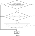
- Figure 3 shows a flowchart of a method for regulating a power grid frequency according to an embodiment of the present disclosure.
- the method for regulating a power grid frequency can be applied to a direct-drive wind turbine and/or a semi-direct-drive wind turbine for regulating the power grid frequency.
- the method for regulating a power grid frequency may be performed by a converter (such as a controller of the converter) of a wind turbine.
- step S201 it is determined whether there is a disturbance in an amplitude of a three-phase voltage at a point of common coupling.
- the decoupled voltage positive sequence component and the filtered voltage positive sequence fundamental component are obtained by performing the method for detecting a power grid frequency described with reference to Figure 1 .
- an amplitude of a high-frequency signal in the decoupled voltage positive sequence component may be obtained based on the decoupled voltage positive sequence component and the filtered voltage positive sequence fundamental component.
- the amplitude of the high-frequency signal is greater than a preset threshold, it is determined that there is a disturbance in the amplitude of the three-phase voltage at the point of common coupling.
- the amplitude of the high-frequency signal may be obtained by calculating the amplitude of pre-filtered and post-filtered signals to thereby determine whether the disturbance occurs.
- equations (3) or (4) can be used to calculate the amplitude ⁇ of the high-frequency signal in the decoupled voltage positive sequence component.
- a disturbance amount may be calculated by using equation (3) so that a high-frequency disturbance component can be effectively extracted while avoiding the influence of a low-frequency component on the calculation.
- the calculation may also be carried out according to equation (4).
- ⁇ ′ ⁇ d n ⁇ + ⁇ q n ⁇ 2 ⁇ ⁇ ⁇ d n ⁇ + ⁇ ⁇ q n ⁇ 2
- a disturbance amount may be calculated by using equation (3) so that a high-frequency disturbance component can be effectively extracted while avoiding the influence of a low-frequency component on the calculation.
- the calculation may also be carried out according to equation (4) or using other variants of the four variables in equation (3).
- a change and fluctuation in the three-phase voltage at the point of common coupling caused by the switching of a filter capacitor can cause a disturbance in the detection of the frequency and the change rate thereof.
- the method for detecting a power grid frequency according to the present disclosure is based on the three-phase voltage at the point of common coupling t. Therefore, when some actions of the wind turbine cause a fluctuation and disturbance in the voltage at the point of common coupling, it will cause a disturbance in the detection of the power grid frequency.
- this disturbance is not a disturbance in the frequency of the power grid itself, but rather a disturbance presented in the detected power grid frequency caused by the disturbance of the voltage at the point of common coupling of the wind turbine.
- step S202 is performed to determine whether a response condition for power grid frequency regulation is met based on a detected power grid frequency and/or a change rate of the power grid frequency.
- the power grid frequency and/or the change rate of the power grid frequency are detected by performing the method for detecting a power grid frequency described with reference to Figure 1 .
- step S201 may be performed based on intermediate variables (such as the decoupled voltage positive sequence component and the filtered voltage positive sequence fundamental component) in the process of detecting a power grid frequency this time.
- steps S202 and S203 are performed based on a detection result of the power grid frequency this time (i.e., the power grid frequency and the change rate thereof).
- the response condition for power grid frequency regulation may include: an inertia response condition and/or a primary frequency regulation response condition.
- step S203 is performed to control a power of a wind turbine to regulate the power grid frequency based on the power grid frequency and/or the change rate of the power grid frequency.
- the inertia response when only the inertia response condition is met, the inertia response may be performed by controlling the power of the wind turbine based on the change rate of the power grid frequency.
- the primary frequency regulation when only the primary frequency regulation response condition is met, the primary frequency regulation may be performed by controlling the power of the wind turbine based on the power grid frequency and the change rate thereof.
- the inertia response when both the inertia response condition and the primary frequency regulation response condition are met, the inertia response may be preferentially performed by controlling the power of the wind turbine based on the change rate of the power grid frequency to provide active support for grid inertia.
- the inertia response when both the inertia response condition and the primary frequency regulation response condition are met, the inertia response is preferentially performed, that is, the inertia response rather than the primary frequency regulation response is performed first at present.
- the inertia response of the power grid often occurs before the primary frequency regulation. Moreover, the inertia response has a high time requirement of a millisecond level and has a short duration. While the primary frequency regulation response has a low time requirement of a second level, and has a long duration. Therefore, it is proposed in the present disclosure that, if the current power grid frequency or the change rate thereof meets the response condition, an active power increment shall be calculated based on the principle of preferentially performing the inertia response.
- the power grid frequency and the change rate thereof are greater than a dead zone.
- a current power of the wind turbine is greater than 20% Pn.
- the response condition for power grid frequency regulation is met. Then, the active power increment at the current power grid frequency and the change rate thereof may be calculated based on an virtual inertia equation.
- the inertia response condition may be set according to specific test standards, such as a determination condition for whether the inertia response acts is as shown in equation (5) below.
- ⁇ f f - f N
- f represents a detected power grid frequency
- f N represents a rated frequency of the power grid
- df 0 represents a threshold of dead zone of the change rate of the frequency.
- the primary frequency regulation response condition may also be set according to standard requirements. For example, as required by the national standard, in a case that the wind turbine is operating under a limited power frequency regulation condition and the active output is greater than 20% Pn, the wind turbine should be able to participate in system frequency regulation and allow system frequency recovery when a frequency deviation at a test point exceeds a threshold (recommended ⁇ 0.2Hz).
- the active power increment for the inertia response may be calculated according to equation (6) (as required by the national standard, the active power increment should be calculated according to the equation (6) to achieve the active support for the inertia response). It should be understood that the active power increment may be a positive value or a negative value.
- ⁇ P ⁇ T J ⁇ N d ⁇ dt P N
- T J represents an inertia time constant
- P N represents a rated power of the generator set
- f N represents a rated frequency of the power grid
- df / dt represents a detected change rate of the power grid frequency.
- the active power increment may also be calculated according to the standard requirements for primary frequency regulation.
- a target value of the active power increment for the wind turbine may be determined based on the power grid frequency and/or the change rate of the power grid frequency; an additional torque value of the generator is calculated based on the target value of the active power increment and a rotation speed of the generator; a target torque value of the generator is calculate based on a torque value and the additional torque value of the generator; and a torque of the generator is controlled based on the target torque value of the generator to control the power of the wind turbine.
- the calculated target value of the active power increment may be uploaded to a main controller of the wind turbine (or a machine-side controller of the converter); the additional torque is calculated by the main controller of the wind turbine or the machine-side controller of the converter based on the target value of the active power increment and the rotation speed of the generator; the current torque can be superimposed by the main controller of the wind turbine or the machine-side controller of the converter to the additional torque value and the superimposed torque is sent to the machine-side controller of the converter for execution.
- the active power support increment may be calculated based on the power grid frequency detection with high-precision and the change rate thereof, and the whole generation set performs the power control based on the value of the active power increment.
- the active output of the wind turbine may be changed by using a control method of converting the active power increment into a kinetic energy of an impeller and a rotor to provide the active support for the inertia of the power grid.
- the active output of the generation set may be changed by using a control method of converting the active power increment into a torque of a motor to provide the active support for the inertia of the power grid.
- the active output of the wind turbine may be changed by the following two methods: (1) a method of adjusting an energy captured by the wind turbine to a wind energy by controlling a pitch angle, to allow the system to execute a demand value of the active power increment; (2) a control method of converting the active power increment into a kinetic energy of an impeller and a rotor, to provide the active support for the power grid frequency regulation.
- the active support for the primary frequency regulation may be achieved by a combination of the two methods. A longer response time is required when the active support for the primary frequency regulation is performed.
- the active support is provided with the kinetic energy of the rotor, that is, the active support is achieved by controlling the torque of the generator, sacrificing the stability of the rotation speed of the generator.
- the active support may be achieved by changing an aerodynamic power of a wind turbine by pitching.
- the target value of the active power increment for the wind turbine may be determined based on the power grid frequency and/or the change rate of the power grid frequency; the value of the active power increment that needs to be regulated for each of multiple control cycles is determined based on the target value of the active power increment; and then, the power of the wind turbine is controlled based on the value of the active power increment that needs to be regulated for each control cycle.
- the multiple control cycles include a current control cycle and a certain number of subsequent control cycles. A sum of the values of the active power increment that need to be regulated for the multiple control cycles is the target value of the active power increment.
- the target value of the active power increment may be set according to a slope (i.e., regulating the power of the wind turbine in a small amount for multiple times), reducing the impact of power shock on the detection of the power grid frequency, and solving the problem of oscillation of the change rage of the power grid frequency and the active support due to the disturbance of the inertia response for the wind turbine during the active support on the frequency detection.
- setting the slope for the active power may also be achieved through low-pass filtering.
- the calculated target value of the active power increment may also be limited in amplitude, and the target value of the active power increment may be set according to the slope.
- the impact of power shock on the detection of the power grid frequency may be reduced by limiting the active power increment in amplitude and setting the active power increment according to the slope.
- the method for regulating a power grid frequency may further include: determining whether to exit a control mode of the inertia response and/or primary frequency regulation based on the power grid frequency and the change rate thereof. If it is determined to exit the control mode of the inertia response and/or primary frequency regulation, the target value of the active power increment may be set to 0, and the target value of the active power increment may be set according to the slope.
- Figure 4 shows a flowchart of a method for regulating a power grid frequency according to another embodiment of the present disclosure.
- step S301 a collected three-phase voltage at a point of common coupling is converted into a two-phase voltage.
- step S302 the two-phase voltage is transformed based on a phase angle of a specific frequency to obtain a voltage positive sequence component to be decoupled and a voltage negative sequence component to be decoupled.
- step S303 the voltage positive sequence component to be decoupled and the voltage negative sequence component to be decoupled are decoupled based on the phase angle, and the decoupled voltage positive sequence component is filtered to obtain a voltage positive sequence fundamental component.
- step S304 an inverse transformation is performed on the voltage positive sequence fundamental component based on the phase angle to obtain a set of orthogonal voltage components in a two-phase stationary coordinate system.
- step S305 a phase angle of the power grid is obtained based on the set of orthogonal voltage components.
- step S306 a power grid frequency and a change rate of the power grid frequency are obtained based on the phase angle of the power grid.
- step S307 it is determined whether there is a disturbance in an amplitude of the three-phase voltage at the point of common coupling.
- step S308 is performed to determine whether a response condition for power grid frequency regulation is met based on the detected power grid frequency and/or the change rate of the power grid frequency.
- step S309 is performed to control a power of the wind turbine based on the power grid frequency and/or the change rate of the power grid frequency to regulate the power grid frequency.
- the detection accuracy of the power grid frequency and the change rate of the power grid frequency may meet the following requirements: a measurement accuracy of the frequency is less than 0.001Hz and a measurement accuracy of the rate change of the frequency is less than 0.002Hz/s.
- the response time for the power grid frequency and the change rate of the power grid frequency may meet the following requirements: a detection time for the frequency and the change rate of the frequency is less than 100ms, and a total time for the inertia response is less than 500ms.
- a frequency offset may be adapted to a range of 40Hz to 70Hz for accurate detection.
- a voltage offset may be adapted to a range of 10% pu to 150% pu of the power grid voltage for accurate detection.
- a three-phase unevenness may be adapted to a case that the two-phase voltage drops to 10%pu, or the two-phase voltage rises to 150%pu, with the requirements for the detection accuracy of the frequency and the change rate of the frequency and the response time met.
- a voltage harmonic may be adapted to a case that a content of a single voltage harmonic of the 2nd, the 3rd, the 5th, the 7th and the like is less than 5%, or a total content of the harmonic is less than 5%, with the requirements for the detection accuracy of the frequency and the change rate of the frequency and the response time met.
- the adaptability of phase mutation may meet the requirements for the detection accuracy of the frequency and the change rate of the frequency and the response time.
- An accuracy of the active power control has an absolute value of an error not exceeding 2% Pn.
- the problem of the misresponse of the inertia and the primary frequency regulation caused by the disturbance generated during the switching of a filter capacitor, sudden power increase, high-voltage ride-through, and low-voltage ride-through in detecting the frequency and the change rate thereof based on the three-phase voltage signal of the power grid has been solved.
- the proposed method may be performed in the controller of the converter to achieve rapid development, application to new models, and on-site modification.
- the problem of oscillation of the change rate of the power grid frequency and the active support due to the disturbance of the inertia response for the wind turbine during the active support on the frequency detection is solved.
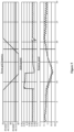
- the change rate of the power grid frequency is -0.5Hz/s.
- the calculated active power increment is 0.07Pn
- the actual waveform is a second waveform of Figure 5 , where the active power increment increases from 0.85Pn to 0.92Pn.
- the active support is achieved through kinetic energy of a rotor, a rotation speed slowly decreases during the active support process, as shown in a third waveform of Figure 5 .
- the response condition is not met, and thus the active output for the generator set remains unchanged.
- a target value of the active power increment is -0.16Pn according to the requirements for the active power
- the actual waveform is a second waveform of Figure 6 , where the active power increment increases from 0.81Pn to 0.65Pn.
- the rotation speed reaches a stable value, as shown in a third waveform of Figure 6 .
- Figure 7 shows a structural block diagram of an apparatus for detecting a power grid frequency according to an embodiment of the present disclosure.
- the apparatus for detecting a power grid frequency includes: a two-phase voltage acquisition unit 101, a transformation unit 102, a decoupling and filtering unit 103, an inverse transformation unit 104, a power grid phase angle acquisition unit 105, and a power grid frequency acquisition unit 106.
- the two-phase voltage acquisition unit 101 is configured to convert a collected three-phase voltage at a point of common coupling into a two-phase voltage.
- the transformation unit 102 is configured to transform the two-phase voltage based on a phase angle of a specific frequency to obtain a voltage positive sequence component to be decoupled and a voltage negative sequence component to be decoupled.
- the decoupling and filtering unit 103 is configured to decouple the voltage positive sequence component to be decoupled and the voltage negative sequence component to be decoupled based on the phase angle, and to filter the decoupled voltage positive sequence component to obtain a voltage positive sequence fundamental component.
- the inverse transformation unit 104 is configured to perform inverse transformation on the voltage positive sequence fundamental component based on the phase angle to obtain a set of orthogonal voltage components in a two-phase stationary coordinate system.
- the power grid phase angle acquisition unit 105 is configured to obtain a phase angle of the power grid based on the set of orthogonal voltage components.
- the power grid frequency acquisition unit 106 is configured to obtain a power grid frequency based on the phase angle of the power grid.
- the phase angle may be obtained by integrating a specific angular velocity.
- the frequency corresponding to the specific angular velocity is the specific frequency.
- the two-phase voltage acquisition unit 101 may be configured to perform bandpass filtering on the collected three-phase voltage at the point of common coupling; and perform Clark equiamplitude transformation on the three-phase voltage subjected to bandpass filtering to obtain a two-phase voltage.
- a central frequency of the bandpass filtering is a rated frequency of the power grid or the power grid frequency detected during a previous detection cycle of the power grid frequency.
- the transformation unit 102 may be configured to perform positive and negative sequence rotation coordinate transformation on the two-phase voltage based on the phase angle, to obtain a voltage positive sequence component to be decoupled in a positive sequence rotation coordinate system and a voltage negative sequence component to be decoupled in a negative sequence rotation coordinate system.
- the positive sequence rotation coordinate system and the negative sequence rotation coordinate system form a dual synchronous rotation coordinate system.
- the decoupling and filtering unit 103 may be configured to filter the decoupled voltage negative sequence component to obtain a voltage negative sequence fundamental component.
- the decoupling and filtering unit 103 may be configured to perform cross feedback decoupling on the voltage positive sequence component to be decoupled based on the phase angle using the voltage negative sequence fundamental component obtained from a previous detection cycle of the power grid frequency to obtain a decoupled voltage positive sequence component, and perform cross feedback decoupling on the voltage negative sequence component to be decoupled based on the phase angle using the voltage positive sequence fundamental component obtained from a previous detection cycle of the power grid frequency to obtain a decoupled voltage negative sequence component.
- the decoupling and filtering unit 103 may be configured to perform band-stop filtering and low-pass filtering on the decoupled voltage positive sequence component to obtain the voltage positive sequence fundamental component.
- a central frequency of the band-stop filtering is a rated frequency of the power grid or the power grid frequency detected during a previous detection cycle of the power grid frequency.
- the specific frequency is higher than a cut-off frequency of the low-pass filtering.
- the power grid frequency acquisition unit 106 may be configured to perform differential calculation on the phase angle of the power grid to obtain a first frequency, filter the first frequency to obtain a second frequency, and obtain the power grid frequency based on the second frequency.
- the apparatus for detecting a power grid frequency may further include: an acquisition unit(not shown) for a change rate of the power grid frequency.
- the acquisition unit is configured to perform differential calculation on the second frequency to obtain a change rate of the second frequency; and filter the change rate of the second frequency to obtain a change rate of the power grid frequency.
- the power grid frequency acquisition unit 106 may be configured to superimpose a product of the change rate of the power grid frequency and a frequency compensation coefficient onto the second frequency, and use a superimposed result as the power grid frequency.
- Figure 8 shows a structural block diagram of an apparatus for regulating a power grid frequency according to an embodiment of the present disclosure.
- the apparatus for regulating a power grid frequency includes: a voltage disturbance determination unit 201, a response condition determination unit 202, and a power grid frequency regulation unit 203.
- the voltage disturbance determination unit 201 is configured to determine whether there is a disturbance in an amplitude of a three-phase voltage at a point of common coupling.
- the response condition determination unit 202 is configured to determine whether a response condition for grid frequency regulation is met based on the detected power grid frequency and/or the change rate of the power grid frequency when there is no disturbance.
- the power grid frequency regulation unit 203 is configured to control a power of a wind turbine based on the power grid frequency and/or the change rate of the power grid frequency when the response condition for grid frequency regulation is met, in order to regulate the power grid frequency.
- the power grid frequency and/or the change rate of the power grid frequency are obtained through the apparatus for detecting a power grid frequency as described in the above embodiment.
- the voltage disturbance determination unit 201 may be configured to determine whether there is a disturbance in the amplitude of the three-phase voltage at the point of common coupling based on the decoupled voltage positive sequence component and the voltage positive sequence fundamental component obtained by filtering the decoupled voltage positive sequence component.
- the decoupled voltage positive sequence component and the filtered voltage positive sequence fundamental component are obtained through the apparatus for detecting a power grid frequency as described in the above embodiment.
- the voltage disturbance determination unit 201 may be configured to obtain an amplitude of a high-frequency signal in the decoupled voltage positive sequence component based on the decoupled voltage positive sequence component and the filtered voltage positive sequence fundamental component, and determine that there is a disturbance in the amplitude of the three-phase voltage at the point of common coupling when the amplitude of the high-frequency signal is greater than a preset threshold.
- the response condition for power grid frequency regulation may include an inertia response condition and a primary frequency regulation response condition.
- the response condition determination unit 202 may be configured to determine whether the inertia response condition is met based on the power grid frequency and the change rate of the power grid frequency, determine whether the primary frequency regulation response condition is met based on the power grid frequency.
- the power grid frequency regulation unit 203 may be configured to preferentially control a power of the wind turbine to perform the inertia response based on the change rate of the power grid frequency when both the inertia response condition and the primary frequency regulation response condition are met.
- the grid frequency regulation unit 203 may be configured to determine a target value of an active power increment for the wind turbine based on the power grid frequency and/or the change rate of the power grid frequency; calculate an additional torque value of the generator based on the target value of the active power increment and a rotation speed of the generator; calculate a target torque value of the generator based on a torque value and the additional torque value of the generator; and control the torque of the generator based on the target torque value of the generator to control a power of the wind turbine.
- the grid frequency regulation unit 203 may be configured to determine a target value of an active power increment for the wind turbine based on the power grid frequency and/or the change rate of the power grid frequency; determine a value of the active power increment that needs to be regulated for each of multiple control cycles based on the target value of the active power increment, where the multiple control cycles include a current control cycle and a subsequent control cycle; and control a power of the wind turbine based on the value of the active power increment that needs to be regulated for each control cycle, where a sum of values of the active power increment that needs to be regulated for the multiple control cycles is the target value of the active power increment.
- various units in the apparatus for detecting a power grid frequency and the apparatus for regulating a power grid frequency may be implemented in hardware components and/or software components. These skilled in the art may implement the various units for example by utilizing a field programmable gate array (FPGA) or an application specific integrated circuit (ASIC) based on the processes performed by various defined units.
- FPGA field programmable gate array
- ASIC application specific integrated circuit
- a computer-readable storage medium storing a computer program is provided according to an embodiment of the present disclosure.
- the computer program when executed by a processor, causes the processor to execute the method for detecting a power grid frequency and the method for regulating a power grid frequency as described in the above embodiment.
- the computer readable storage medium may be any data storage apparatus capable of storing data that is read by a computer system. Examples of the computer readable storage medium include: a read only memory, a random access memory, a read only optical disc, a magnetic tape, a floppy disk, an optical data storage apparatus, and a carrier wave (such as data transmission through the Internet via a wired or wireless transmission path).
- the electronic device includes a processor (not shown) and a memory (not shown).
- the memory stores a computer program that, when executed by the processor, causes the processor to execute the method for detecting a power grid frequency and the method for regulating a power grid frequency as described in the above embodiment.
- the electronic device may be a controller of the wind turbine or a converter (e.g.,, a controller of the converter).
- a computer program downloadable from a communication network and/or stored on a machine readable storage medium is provided according to an embodiment of the present disclosure.
- the computer program includes program code instructions for implementing the method for detecting a power grid frequency as described in the above embodiment and/or for implementing the method for regulating a power grid frequency as described in the above embodiment.
Landscapes
- Engineering & Computer Science (AREA)
- Power Engineering (AREA)
- Physics & Mathematics (AREA)
- General Physics & Mathematics (AREA)
- Mathematical Physics (AREA)
- Supply And Distribution Of Alternating Current (AREA)
- Control Of Eletrric Generators (AREA)
Applications Claiming Priority (2)
| Application Number | Priority Date | Filing Date | Title |
|---|---|---|---|
| CN202111136677.4A CN114280363B (zh) | 2021-09-27 | 2021-09-27 | 电网频率检测方法和装置及电网频率调节方法和装置 |
| PCT/CN2022/102858 WO2023045469A1 (zh) | 2021-09-27 | 2022-06-30 | 电网频率检测方法和装置及电网频率调节方法和装置 |
Publications (2)
| Publication Number | Publication Date |
|---|---|
| EP4375682A1 true EP4375682A1 (de) | 2024-05-29 |
| EP4375682A4 EP4375682A4 (de) | 2025-01-22 |
Family
ID=80868574
Family Applications (1)
| Application Number | Title | Priority Date | Filing Date |
|---|---|---|---|
| EP22871530.6A Pending EP4375682A4 (de) | 2021-09-27 | 2022-06-30 | Verfahren zur erkennung der frequenz eines stromnetzes, vorrichtung, verfahren zur einstellung der frequenz eines stromnetzes und vorrichtung |
Country Status (6)
| Country | Link |
|---|---|
| US (1) | US20240429718A1 (de) |
| EP (1) | EP4375682A4 (de) |
| KR (1) | KR20240050378A (de) |
| CN (1) | CN114280363B (de) |
| AU (1) | AU2022349378B2 (de) |
| WO (1) | WO2023045469A1 (de) |
Families Citing this family (4)
| Publication number | Priority date | Publication date | Assignee | Title |
|---|---|---|---|---|
| CN114280363B (zh) * | 2021-09-27 | 2024-05-10 | 金风科技股份有限公司 | 电网频率检测方法和装置及电网频率调节方法和装置 |
| US12142922B2 (en) | 2022-09-01 | 2024-11-12 | Caterpillar Inc. | Techniques for limiting power using an active front end |
| CN115980444A (zh) * | 2022-11-25 | 2023-04-18 | 贵州电网有限责任公司 | 一种自适应瞬时频率及频率变换率测量系统及方法 |
| CN117269654B (zh) * | 2023-11-17 | 2024-03-15 | 中国电力科学研究院有限公司 | 构网型变流器相位跳变有功响应特性测试评估方法及装置 |
Family Cites Families (18)
| Publication number | Priority date | Publication date | Assignee | Title |
|---|---|---|---|---|
| CN102305886B (zh) * | 2011-05-31 | 2013-07-24 | 浙江大学 | 电网电压谐波畸变及不平衡时基波电压同步信号检测方法 |
| JP5721645B2 (ja) * | 2012-02-06 | 2015-05-20 | 三菱重工業株式会社 | 風力発電装置の制御装置、風力発電装置、及び風力発電装置の制御方法 |
| CN102735938A (zh) * | 2012-07-09 | 2012-10-17 | 华北电力大学(保定) | 一种电网电压基波正序相角的快速检测方法 |
| KR101438042B1 (ko) * | 2013-03-25 | 2014-09-04 | 엘에스산전 주식회사 | 계통 연계형 인버터 및 그의 제어 방법 |
| JP6423757B2 (ja) * | 2015-06-04 | 2018-11-14 | 株式会社ダイヘン | 周波数検出装置、周波数検出方法、および、検出された周波数を用いるインバータ装置 |
| CN106300386B (zh) * | 2015-06-10 | 2019-06-04 | 特变电工新疆新能源股份有限公司 | 基于svg动态抑制电网次同步振荡的频率闭环控制方法 |
| CN105162137B (zh) * | 2015-09-12 | 2018-04-10 | 南昌航空大学 | 复杂电网下无功及谐波电流检测算法 |
| CN105633986B (zh) * | 2016-03-03 | 2017-10-31 | 甘肃省电力公司风电技术中心 | 基于动态同步信号定向的并网变换器暂态控制方法 |
| CN105914776B (zh) * | 2016-04-13 | 2019-05-24 | 上海交通大学 | 具有电网故障自愈能力的快速智能反孤岛系统和方法 |
| CN106533238A (zh) * | 2016-12-09 | 2017-03-22 | 国网辽宁省电力有限公司营口供电公司 | 一种基于电压补偿的船舶电气系统并网逆变器的控制方法 |
| CN107831365A (zh) * | 2017-07-03 | 2018-03-23 | 中国农业大学 | 一种基于移动平均滤波器对电网相角检测的开环同步方法 |
| CN109358228B (zh) * | 2018-11-09 | 2020-12-15 | 哈工大(张家口)工业技术研究院 | 基于双增强型锁相环的电网电压正负序分量实时估计方法 |
| CN109659983B (zh) * | 2018-11-26 | 2020-07-07 | 合肥科威尔电源系统股份有限公司 | 基于idft的软件锁相环实现方法及装置 |
| CN109474011B (zh) * | 2018-11-26 | 2020-09-08 | 华中科技大学 | 一种三相并网集成充电器的电流控制方法及控制系统 |
| CN110365018B (zh) * | 2019-07-18 | 2022-03-29 | 国电南瑞科技股份有限公司 | 一种自适应宽频带正负序分离方法 |
| CN111030193A (zh) * | 2019-12-06 | 2020-04-17 | 国网电力科学研究院有限公司 | 一种风电场参与电网快速调频调压的控制方法、装置和系统 |
| CN113381452B (zh) * | 2021-07-16 | 2022-11-25 | 苏州大学 | 一种基于四采样法转换延时的锁频方法及装置 |
| CN114280363B (zh) * | 2021-09-27 | 2024-05-10 | 金风科技股份有限公司 | 电网频率检测方法和装置及电网频率调节方法和装置 |
-
2021
- 2021-09-27 CN CN202111136677.4A patent/CN114280363B/zh active Active
-
2022
- 2022-06-30 AU AU2022349378A patent/AU2022349378B2/en active Active
- 2022-06-30 EP EP22871530.6A patent/EP4375682A4/de active Pending
- 2022-06-30 KR KR1020247008817A patent/KR20240050378A/ko active Pending
- 2022-06-30 WO PCT/CN2022/102858 patent/WO2023045469A1/zh not_active Ceased
- 2022-06-30 US US18/684,738 patent/US20240429718A1/en active Pending
Also Published As
| Publication number | Publication date |
|---|---|
| KR20240050378A (ko) | 2024-04-18 |
| CN114280363B (zh) | 2024-05-10 |
| AU2022349378A1 (en) | 2024-03-07 |
| AU2022349378B2 (en) | 2026-02-05 |
| WO2023045469A1 (zh) | 2023-03-30 |
| US20240429718A1 (en) | 2024-12-26 |
| EP4375682A4 (de) | 2025-01-22 |
| CN114280363A (zh) | 2022-04-05 |
Similar Documents
| Publication | Publication Date | Title |
|---|---|---|
| EP4375682A1 (de) | Verfahren zur erkennung der frequenz eines stromnetzes, vorrichtung, verfahren zur einstellung der frequenz eines stromnetzes und vorrichtung | |
| US20200335978A1 (en) | Adaptive Control Method for Output Feedback of Virtual Synchronous Generator | |
| US10084403B2 (en) | Power supply system and control method therefor | |
| US9941828B2 (en) | System and method for stabilizing sub-synchronous interaction of a wind turbine generator | |
| CN107634524B (zh) | 一种应用于虚拟同步发电机控制器的附加阻尼控制方法 | |
| US11296629B2 (en) | Method, device for sub synchronous oscillation suppression and controller for converter | |
| CN106981878A (zh) | 一种基于自抗扰控制的双馈风机抑制电网低频振荡的方法 | |
| CN113098033B (zh) | 基于柔性直流输电系统的自适应虚拟惯量控制系统及方法 | |
| CN112542855A (zh) | 一种双馈风力发电系统相量模型建模及仿真方法 | |
| CN115719975A (zh) | 一种风电场等效虚拟惯量常数在线评估方法、装置及存储介质 | |
| CN113675862B (zh) | 一种双馈风机等效惯量评估方法及系统 | |
| CN114629112A (zh) | 基于二阶广义积分器的锁频环及其控制方法 | |
| CN103208817B (zh) | 一种基于二阶滑模的dfig控制方法 | |
| He et al. | Novel adaptive power control of a Direct-drive PM wind generation system in a micro grid | |
| CN120454177A (zh) | 一种基于虚拟同步发电机的并网逆变器故障穿越方法及相关设备 | |
| Long et al. | Analysis of sub-synchronous oscillations on hybrid wind farms with DFIG and PMSG | |
| CN116031900A (zh) | 风火储送出系统在短路故障下的频率特性分析方法及系统 | |
| Dinesh et al. | Independent operation of DFIG-based WECS using resonant feedback compensators under unbalanced grid voltage conditions | |
| CN115085271B (zh) | 基于故障穿越过程的直驱风机的有功功率计算方法及系统 | |
| EP4572064A1 (de) | Verfahren zur dämpfung von stromschwingungen in einem stromnetz | |
| Liu et al. | Analysis of direct power control strategies applied to doubly fed induction generator | |
| Zhang et al. | Online Identification Based on Time-Frequency Transformation for Equivalent Virtual Inertia Constant of Wind Farm | |
| Hashemnia et al. | A New Method for DFIG Control under Unbalanced Grid Voltage Conditions | |
| Li et al. | Control Strategy and Simulation Analysis of Direct-Drive Fan and Weak Power Grid based on RTDS | |
| CN120150169A (zh) | 一种不对称故障时正负序分离控制方法 |
Legal Events
| Date | Code | Title | Description |
|---|---|---|---|
| STAA | Information on the status of an ep patent application or granted ep patent |
Free format text: STATUS: THE INTERNATIONAL PUBLICATION HAS BEEN MADE |
|
| PUAI | Public reference made under article 153(3) epc to a published international application that has entered the european phase |
Free format text: ORIGINAL CODE: 0009012 |
|
| STAA | Information on the status of an ep patent application or granted ep patent |
Free format text: STATUS: REQUEST FOR EXAMINATION WAS MADE |
|
| 17P | Request for examination filed |
Effective date: 20240212 |
|
| AK | Designated contracting states |
Kind code of ref document: A1 Designated state(s): AL AT BE BG CH CY CZ DE DK EE ES FI FR GB GR HR HU IE IS IT LI LT LU LV MC MK MT NL NO PL PT RO RS SE SI SK SM TR |
|
| DAV | Request for validation of the european patent (deleted) | ||
| DAX | Request for extension of the european patent (deleted) | ||
| A4 | Supplementary search report drawn up and despatched |
Effective date: 20241220 |
|
| RIC1 | Information provided on ipc code assigned before grant |
Ipc: H02J 3/48 20060101ALI20241217BHEP Ipc: H02J 3/38 20060101ALI20241217BHEP Ipc: H02J 3/24 20060101ALI20241217BHEP Ipc: G01R 19/25 20060101ALI20241217BHEP Ipc: G01R 23/02 20060101AFI20241217BHEP |