EP4375540A1 - Triebstrang für pumpen, energieerzeugungsanlagen oder dergleichen und verfahren zum anfahren eines solchen triebstranges - Google Patents
Triebstrang für pumpen, energieerzeugungsanlagen oder dergleichen und verfahren zum anfahren eines solchen triebstranges Download PDFInfo
- Publication number
- EP4375540A1 EP4375540A1 EP23179757.2A EP23179757A EP4375540A1 EP 4375540 A1 EP4375540 A1 EP 4375540A1 EP 23179757 A EP23179757 A EP 23179757A EP 4375540 A1 EP4375540 A1 EP 4375540A1
- Authority
- EP
- European Patent Office
- Prior art keywords
- drive
- differential
- machine
- gear
- speed
- Prior art date
- Legal status (The legal status is an assumption and is not a legal conclusion. Google has not performed a legal analysis and makes no representation as to the accuracy of the status listed.)
- Pending
Links
- 238000000034 method Methods 0.000 title claims description 26
- 230000005540 biological transmission Effects 0.000 claims description 20
- 230000001360 synchronised effect Effects 0.000 claims description 20
- 239000010687 lubricating oil Substances 0.000 claims description 7
- 230000002706 hydrostatic effect Effects 0.000 claims description 5
- 238000002485 combustion reaction Methods 0.000 claims description 4
- 210000000078 claw Anatomy 0.000 claims description 2
- 230000010363 phase shift Effects 0.000 claims 1
- 230000001105 regulatory effect Effects 0.000 description 8
- 230000006978 adaptation Effects 0.000 description 7
- 230000008878 coupling Effects 0.000 description 7
- 238000010168 coupling process Methods 0.000 description 7
- 238000005859 coupling reaction Methods 0.000 description 7
- 230000007257 malfunction Effects 0.000 description 6
- 230000007704 transition Effects 0.000 description 4
- 238000005516 engineering process Methods 0.000 description 3
- 230000008569 process Effects 0.000 description 3
- 230000003313 weakening effect Effects 0.000 description 3
- 230000008901 benefit Effects 0.000 description 2
- 230000007423 decrease Effects 0.000 description 2
- 238000010586 diagram Methods 0.000 description 2
- 238000005461 lubrication Methods 0.000 description 2
- 230000002123 temporal effect Effects 0.000 description 2
- XLYOFNOQVPJJNP-UHFFFAOYSA-N water Substances O XLYOFNOQVPJJNP-UHFFFAOYSA-N 0.000 description 2
- 230000001133 acceleration Effects 0.000 description 1
- 230000004913 activation Effects 0.000 description 1
- 238000006243 chemical reaction Methods 0.000 description 1
- 230000009849 deactivation Effects 0.000 description 1
- 230000008030 elimination Effects 0.000 description 1
- 238000003379 elimination reaction Methods 0.000 description 1
- 239000012530 fluid Substances 0.000 description 1
- 238000012423 maintenance Methods 0.000 description 1
Images


Classifications
-
- F—MECHANICAL ENGINEERING; LIGHTING; HEATING; WEAPONS; BLASTING
- F16—ENGINEERING ELEMENTS AND UNITS; GENERAL MEASURES FOR PRODUCING AND MAINTAINING EFFECTIVE FUNCTIONING OF MACHINES OR INSTALLATIONS; THERMAL INSULATION IN GENERAL
- F16H—GEARING
- F16H3/00—Toothed gearings for conveying rotary motion with variable gear ratio or for reversing rotary motion
- F16H3/44—Toothed gearings for conveying rotary motion with variable gear ratio or for reversing rotary motion using gears having orbital motion
- F16H3/72—Toothed gearings for conveying rotary motion with variable gear ratio or for reversing rotary motion using gears having orbital motion with a secondary drive, e.g. regulating motor, in order to vary speed continuously
- F16H3/724—Toothed gearings for conveying rotary motion with variable gear ratio or for reversing rotary motion using gears having orbital motion with a secondary drive, e.g. regulating motor, in order to vary speed continuously using external powered electric machines
-
- B—PERFORMING OPERATIONS; TRANSPORTING
- B60—VEHICLES IN GENERAL
- B60K—ARRANGEMENT OR MOUNTING OF PROPULSION UNITS OR OF TRANSMISSIONS IN VEHICLES; ARRANGEMENT OR MOUNTING OF PLURAL DIVERSE PRIME-MOVERS IN VEHICLES; AUXILIARY DRIVES FOR VEHICLES; INSTRUMENTATION OR DASHBOARDS FOR VEHICLES; ARRANGEMENTS IN CONNECTION WITH COOLING, AIR INTAKE, GAS EXHAUST OR FUEL SUPPLY OF PROPULSION UNITS IN VEHICLES
- B60K6/00—Arrangement or mounting of plural diverse prime-movers for mutual or common propulsion, e.g. hybrid propulsion systems comprising electric motors and internal combustion engines ; Control systems therefor, i.e. systems controlling two or more prime movers, or controlling one of these prime movers and any of the transmission, drive or drive units Informative references: mechanical gearings with secondary electric drive F16H3/72; arrangements for handling mechanical energy structurally associated with the dynamo-electric machine H02K7/00; machines comprising structurally interrelated motor and generator parts H02K51/00; dynamo-electric machines not otherwise provided for in H02K see H02K99/00
- B60K6/20—Arrangement or mounting of plural diverse prime-movers for mutual or common propulsion, e.g. hybrid propulsion systems comprising electric motors and internal combustion engines ; Control systems therefor, i.e. systems controlling two or more prime movers, or controlling one of these prime movers and any of the transmission, drive or drive units Informative references: mechanical gearings with secondary electric drive F16H3/72; arrangements for handling mechanical energy structurally associated with the dynamo-electric machine H02K7/00; machines comprising structurally interrelated motor and generator parts H02K51/00; dynamo-electric machines not otherwise provided for in H02K see H02K99/00 the prime-movers consisting of electric motors and internal combustion engines, e.g. HEVs
- B60K6/42—Arrangement or mounting of plural diverse prime-movers for mutual or common propulsion, e.g. hybrid propulsion systems comprising electric motors and internal combustion engines ; Control systems therefor, i.e. systems controlling two or more prime movers, or controlling one of these prime movers and any of the transmission, drive or drive units Informative references: mechanical gearings with secondary electric drive F16H3/72; arrangements for handling mechanical energy structurally associated with the dynamo-electric machine H02K7/00; machines comprising structurally interrelated motor and generator parts H02K51/00; dynamo-electric machines not otherwise provided for in H02K see H02K99/00 the prime-movers consisting of electric motors and internal combustion engines, e.g. HEVs characterised by the architecture of the hybrid electric vehicle
- B60K6/48—Parallel type
-
- B—PERFORMING OPERATIONS; TRANSPORTING
- B60—VEHICLES IN GENERAL
- B60K—ARRANGEMENT OR MOUNTING OF PROPULSION UNITS OR OF TRANSMISSIONS IN VEHICLES; ARRANGEMENT OR MOUNTING OF PLURAL DIVERSE PRIME-MOVERS IN VEHICLES; AUXILIARY DRIVES FOR VEHICLES; INSTRUMENTATION OR DASHBOARDS FOR VEHICLES; ARRANGEMENTS IN CONNECTION WITH COOLING, AIR INTAKE, GAS EXHAUST OR FUEL SUPPLY OF PROPULSION UNITS IN VEHICLES
- B60K6/00—Arrangement or mounting of plural diverse prime-movers for mutual or common propulsion, e.g. hybrid propulsion systems comprising electric motors and internal combustion engines ; Control systems therefor, i.e. systems controlling two or more prime movers, or controlling one of these prime movers and any of the transmission, drive or drive units Informative references: mechanical gearings with secondary electric drive F16H3/72; arrangements for handling mechanical energy structurally associated with the dynamo-electric machine H02K7/00; machines comprising structurally interrelated motor and generator parts H02K51/00; dynamo-electric machines not otherwise provided for in H02K see H02K99/00
- B60K6/20—Arrangement or mounting of plural diverse prime-movers for mutual or common propulsion, e.g. hybrid propulsion systems comprising electric motors and internal combustion engines ; Control systems therefor, i.e. systems controlling two or more prime movers, or controlling one of these prime movers and any of the transmission, drive or drive units Informative references: mechanical gearings with secondary electric drive F16H3/72; arrangements for handling mechanical energy structurally associated with the dynamo-electric machine H02K7/00; machines comprising structurally interrelated motor and generator parts H02K51/00; dynamo-electric machines not otherwise provided for in H02K see H02K99/00 the prime-movers consisting of electric motors and internal combustion engines, e.g. HEVs
- B60K6/22—Arrangement or mounting of plural diverse prime-movers for mutual or common propulsion, e.g. hybrid propulsion systems comprising electric motors and internal combustion engines ; Control systems therefor, i.e. systems controlling two or more prime movers, or controlling one of these prime movers and any of the transmission, drive or drive units Informative references: mechanical gearings with secondary electric drive F16H3/72; arrangements for handling mechanical energy structurally associated with the dynamo-electric machine H02K7/00; machines comprising structurally interrelated motor and generator parts H02K51/00; dynamo-electric machines not otherwise provided for in H02K see H02K99/00 the prime-movers consisting of electric motors and internal combustion engines, e.g. HEVs characterised by apparatus, components or means specially adapted for HEVs
- B60K6/36—Arrangement or mounting of plural diverse prime-movers for mutual or common propulsion, e.g. hybrid propulsion systems comprising electric motors and internal combustion engines ; Control systems therefor, i.e. systems controlling two or more prime movers, or controlling one of these prime movers and any of the transmission, drive or drive units Informative references: mechanical gearings with secondary electric drive F16H3/72; arrangements for handling mechanical energy structurally associated with the dynamo-electric machine H02K7/00; machines comprising structurally interrelated motor and generator parts H02K51/00; dynamo-electric machines not otherwise provided for in H02K see H02K99/00 the prime-movers consisting of electric motors and internal combustion engines, e.g. HEVs characterised by apparatus, components or means specially adapted for HEVs characterised by the transmission gearings
- B60K6/365—Arrangement or mounting of plural diverse prime-movers for mutual or common propulsion, e.g. hybrid propulsion systems comprising electric motors and internal combustion engines ; Control systems therefor, i.e. systems controlling two or more prime movers, or controlling one of these prime movers and any of the transmission, drive or drive units Informative references: mechanical gearings with secondary electric drive F16H3/72; arrangements for handling mechanical energy structurally associated with the dynamo-electric machine H02K7/00; machines comprising structurally interrelated motor and generator parts H02K51/00; dynamo-electric machines not otherwise provided for in H02K see H02K99/00 the prime-movers consisting of electric motors and internal combustion engines, e.g. HEVs characterised by apparatus, components or means specially adapted for HEVs characterised by the transmission gearings with the gears having orbital motion
-
- B—PERFORMING OPERATIONS; TRANSPORTING
- B60—VEHICLES IN GENERAL
- B60K—ARRANGEMENT OR MOUNTING OF PROPULSION UNITS OR OF TRANSMISSIONS IN VEHICLES; ARRANGEMENT OR MOUNTING OF PLURAL DIVERSE PRIME-MOVERS IN VEHICLES; AUXILIARY DRIVES FOR VEHICLES; INSTRUMENTATION OR DASHBOARDS FOR VEHICLES; ARRANGEMENTS IN CONNECTION WITH COOLING, AIR INTAKE, GAS EXHAUST OR FUEL SUPPLY OF PROPULSION UNITS IN VEHICLES
- B60K6/00—Arrangement or mounting of plural diverse prime-movers for mutual or common propulsion, e.g. hybrid propulsion systems comprising electric motors and internal combustion engines ; Control systems therefor, i.e. systems controlling two or more prime movers, or controlling one of these prime movers and any of the transmission, drive or drive units Informative references: mechanical gearings with secondary electric drive F16H3/72; arrangements for handling mechanical energy structurally associated with the dynamo-electric machine H02K7/00; machines comprising structurally interrelated motor and generator parts H02K51/00; dynamo-electric machines not otherwise provided for in H02K see H02K99/00
- B60K6/20—Arrangement or mounting of plural diverse prime-movers for mutual or common propulsion, e.g. hybrid propulsion systems comprising electric motors and internal combustion engines ; Control systems therefor, i.e. systems controlling two or more prime movers, or controlling one of these prime movers and any of the transmission, drive or drive units Informative references: mechanical gearings with secondary electric drive F16H3/72; arrangements for handling mechanical energy structurally associated with the dynamo-electric machine H02K7/00; machines comprising structurally interrelated motor and generator parts H02K51/00; dynamo-electric machines not otherwise provided for in H02K see H02K99/00 the prime-movers consisting of electric motors and internal combustion engines, e.g. HEVs
- B60K6/22—Arrangement or mounting of plural diverse prime-movers for mutual or common propulsion, e.g. hybrid propulsion systems comprising electric motors and internal combustion engines ; Control systems therefor, i.e. systems controlling two or more prime movers, or controlling one of these prime movers and any of the transmission, drive or drive units Informative references: mechanical gearings with secondary electric drive F16H3/72; arrangements for handling mechanical energy structurally associated with the dynamo-electric machine H02K7/00; machines comprising structurally interrelated motor and generator parts H02K51/00; dynamo-electric machines not otherwise provided for in H02K see H02K99/00 the prime-movers consisting of electric motors and internal combustion engines, e.g. HEVs characterised by apparatus, components or means specially adapted for HEVs
- B60K6/38—Arrangement or mounting of plural diverse prime-movers for mutual or common propulsion, e.g. hybrid propulsion systems comprising electric motors and internal combustion engines ; Control systems therefor, i.e. systems controlling two or more prime movers, or controlling one of these prime movers and any of the transmission, drive or drive units Informative references: mechanical gearings with secondary electric drive F16H3/72; arrangements for handling mechanical energy structurally associated with the dynamo-electric machine H02K7/00; machines comprising structurally interrelated motor and generator parts H02K51/00; dynamo-electric machines not otherwise provided for in H02K see H02K99/00 the prime-movers consisting of electric motors and internal combustion engines, e.g. HEVs characterised by apparatus, components or means specially adapted for HEVs characterised by the driveline clutches
- B60K6/387—Actuated clutches, i.e. clutches engaged or disengaged by electric, hydraulic or mechanical actuating means
-
- F—MECHANICAL ENGINEERING; LIGHTING; HEATING; WEAPONS; BLASTING
- F03—MACHINES OR ENGINES FOR LIQUIDS; WIND, SPRING, OR WEIGHT MOTORS; PRODUCING MECHANICAL POWER OR A REACTIVE PROPULSIVE THRUST, NOT OTHERWISE PROVIDED FOR
- F03D—WIND MOTORS
- F03D15/00—Transmission of mechanical power
-
- F—MECHANICAL ENGINEERING; LIGHTING; HEATING; WEAPONS; BLASTING
- F16—ENGINEERING ELEMENTS AND UNITS; GENERAL MEASURES FOR PRODUCING AND MAINTAINING EFFECTIVE FUNCTIONING OF MACHINES OR INSTALLATIONS; THERMAL INSULATION IN GENERAL
- F16H—GEARING
- F16H3/00—Toothed gearings for conveying rotary motion with variable gear ratio or for reversing rotary motion
- F16H3/44—Toothed gearings for conveying rotary motion with variable gear ratio or for reversing rotary motion using gears having orbital motion
- F16H3/72—Toothed gearings for conveying rotary motion with variable gear ratio or for reversing rotary motion using gears having orbital motion with a secondary drive, e.g. regulating motor, in order to vary speed continuously
-
- H—ELECTRICITY
- H02—GENERATION; CONVERSION OR DISTRIBUTION OF ELECTRIC POWER
- H02K—DYNAMO-ELECTRIC MACHINES
- H02K7/00—Arrangements for handling mechanical energy structurally associated with dynamo-electric machines, e.g. structural association with mechanical driving motors or auxiliary dynamo-electric machines
- H02K7/10—Structural association with clutches, brakes, gears, pulleys or mechanical starters
- H02K7/116—Structural association with clutches, brakes, gears, pulleys or mechanical starters with gears
-
- H—ELECTRICITY
- H02—GENERATION; CONVERSION OR DISTRIBUTION OF ELECTRIC POWER
- H02P—CONTROL OR REGULATION OF ELECTRIC MOTORS, ELECTRIC GENERATORS OR DYNAMO-ELECTRIC CONVERTERS; CONTROLLING TRANSFORMERS, REACTORS OR CHOKE COILS
- H02P5/00—Arrangements specially adapted for regulating or controlling the speed or torque of two or more electric motors
- H02P5/74—Arrangements specially adapted for regulating or controlling the speed or torque of two or more electric motors controlling two or more ac dynamo-electric motors
- H02P5/747—Arrangements specially adapted for regulating or controlling the speed or torque of two or more electric motors controlling two or more ac dynamo-electric motors mechanically coupled by gearing
- H02P5/753—Differential gearing
-
- B—PERFORMING OPERATIONS; TRANSPORTING
- B60—VEHICLES IN GENERAL
- B60K—ARRANGEMENT OR MOUNTING OF PROPULSION UNITS OR OF TRANSMISSIONS IN VEHICLES; ARRANGEMENT OR MOUNTING OF PLURAL DIVERSE PRIME-MOVERS IN VEHICLES; AUXILIARY DRIVES FOR VEHICLES; INSTRUMENTATION OR DASHBOARDS FOR VEHICLES; ARRANGEMENTS IN CONNECTION WITH COOLING, AIR INTAKE, GAS EXHAUST OR FUEL SUPPLY OF PROPULSION UNITS IN VEHICLES
- B60K6/00—Arrangement or mounting of plural diverse prime-movers for mutual or common propulsion, e.g. hybrid propulsion systems comprising electric motors and internal combustion engines ; Control systems therefor, i.e. systems controlling two or more prime movers, or controlling one of these prime movers and any of the transmission, drive or drive units Informative references: mechanical gearings with secondary electric drive F16H3/72; arrangements for handling mechanical energy structurally associated with the dynamo-electric machine H02K7/00; machines comprising structurally interrelated motor and generator parts H02K51/00; dynamo-electric machines not otherwise provided for in H02K see H02K99/00
- B60K6/20—Arrangement or mounting of plural diverse prime-movers for mutual or common propulsion, e.g. hybrid propulsion systems comprising electric motors and internal combustion engines ; Control systems therefor, i.e. systems controlling two or more prime movers, or controlling one of these prime movers and any of the transmission, drive or drive units Informative references: mechanical gearings with secondary electric drive F16H3/72; arrangements for handling mechanical energy structurally associated with the dynamo-electric machine H02K7/00; machines comprising structurally interrelated motor and generator parts H02K51/00; dynamo-electric machines not otherwise provided for in H02K see H02K99/00 the prime-movers consisting of electric motors and internal combustion engines, e.g. HEVs
- B60K6/22—Arrangement or mounting of plural diverse prime-movers for mutual or common propulsion, e.g. hybrid propulsion systems comprising electric motors and internal combustion engines ; Control systems therefor, i.e. systems controlling two or more prime movers, or controlling one of these prime movers and any of the transmission, drive or drive units Informative references: mechanical gearings with secondary electric drive F16H3/72; arrangements for handling mechanical energy structurally associated with the dynamo-electric machine H02K7/00; machines comprising structurally interrelated motor and generator parts H02K51/00; dynamo-electric machines not otherwise provided for in H02K see H02K99/00 the prime-movers consisting of electric motors and internal combustion engines, e.g. HEVs characterised by apparatus, components or means specially adapted for HEVs
- B60K6/26—Arrangement or mounting of plural diverse prime-movers for mutual or common propulsion, e.g. hybrid propulsion systems comprising electric motors and internal combustion engines ; Control systems therefor, i.e. systems controlling two or more prime movers, or controlling one of these prime movers and any of the transmission, drive or drive units Informative references: mechanical gearings with secondary electric drive F16H3/72; arrangements for handling mechanical energy structurally associated with the dynamo-electric machine H02K7/00; machines comprising structurally interrelated motor and generator parts H02K51/00; dynamo-electric machines not otherwise provided for in H02K see H02K99/00 the prime-movers consisting of electric motors and internal combustion engines, e.g. HEVs characterised by apparatus, components or means specially adapted for HEVs characterised by the motors or the generators
- B60K2006/268—Electric drive motor starts the engine, i.e. used as starter motor
-
- B—PERFORMING OPERATIONS; TRANSPORTING
- B60—VEHICLES IN GENERAL
- B60K—ARRANGEMENT OR MOUNTING OF PROPULSION UNITS OR OF TRANSMISSIONS IN VEHICLES; ARRANGEMENT OR MOUNTING OF PLURAL DIVERSE PRIME-MOVERS IN VEHICLES; AUXILIARY DRIVES FOR VEHICLES; INSTRUMENTATION OR DASHBOARDS FOR VEHICLES; ARRANGEMENTS IN CONNECTION WITH COOLING, AIR INTAKE, GAS EXHAUST OR FUEL SUPPLY OF PROPULSION UNITS IN VEHICLES
- B60K6/00—Arrangement or mounting of plural diverse prime-movers for mutual or common propulsion, e.g. hybrid propulsion systems comprising electric motors and internal combustion engines ; Control systems therefor, i.e. systems controlling two or more prime movers, or controlling one of these prime movers and any of the transmission, drive or drive units Informative references: mechanical gearings with secondary electric drive F16H3/72; arrangements for handling mechanical energy structurally associated with the dynamo-electric machine H02K7/00; machines comprising structurally interrelated motor and generator parts H02K51/00; dynamo-electric machines not otherwise provided for in H02K see H02K99/00
- B60K6/20—Arrangement or mounting of plural diverse prime-movers for mutual or common propulsion, e.g. hybrid propulsion systems comprising electric motors and internal combustion engines ; Control systems therefor, i.e. systems controlling two or more prime movers, or controlling one of these prime movers and any of the transmission, drive or drive units Informative references: mechanical gearings with secondary electric drive F16H3/72; arrangements for handling mechanical energy structurally associated with the dynamo-electric machine H02K7/00; machines comprising structurally interrelated motor and generator parts H02K51/00; dynamo-electric machines not otherwise provided for in H02K see H02K99/00 the prime-movers consisting of electric motors and internal combustion engines, e.g. HEVs
- B60K6/42—Arrangement or mounting of plural diverse prime-movers for mutual or common propulsion, e.g. hybrid propulsion systems comprising electric motors and internal combustion engines ; Control systems therefor, i.e. systems controlling two or more prime movers, or controlling one of these prime movers and any of the transmission, drive or drive units Informative references: mechanical gearings with secondary electric drive F16H3/72; arrangements for handling mechanical energy structurally associated with the dynamo-electric machine H02K7/00; machines comprising structurally interrelated motor and generator parts H02K51/00; dynamo-electric machines not otherwise provided for in H02K see H02K99/00 the prime-movers consisting of electric motors and internal combustion engines, e.g. HEVs characterised by the architecture of the hybrid electric vehicle
- B60K6/48—Parallel type
- B60K2006/4816—Electric machine connected or connectable to gearbox internal shaft
-
- B—PERFORMING OPERATIONS; TRANSPORTING
- B60—VEHICLES IN GENERAL
- B60K—ARRANGEMENT OR MOUNTING OF PROPULSION UNITS OR OF TRANSMISSIONS IN VEHICLES; ARRANGEMENT OR MOUNTING OF PLURAL DIVERSE PRIME-MOVERS IN VEHICLES; AUXILIARY DRIVES FOR VEHICLES; INSTRUMENTATION OR DASHBOARDS FOR VEHICLES; ARRANGEMENTS IN CONNECTION WITH COOLING, AIR INTAKE, GAS EXHAUST OR FUEL SUPPLY OF PROPULSION UNITS IN VEHICLES
- B60K6/00—Arrangement or mounting of plural diverse prime-movers for mutual or common propulsion, e.g. hybrid propulsion systems comprising electric motors and internal combustion engines ; Control systems therefor, i.e. systems controlling two or more prime movers, or controlling one of these prime movers and any of the transmission, drive or drive units Informative references: mechanical gearings with secondary electric drive F16H3/72; arrangements for handling mechanical energy structurally associated with the dynamo-electric machine H02K7/00; machines comprising structurally interrelated motor and generator parts H02K51/00; dynamo-electric machines not otherwise provided for in H02K see H02K99/00
- B60K6/20—Arrangement or mounting of plural diverse prime-movers for mutual or common propulsion, e.g. hybrid propulsion systems comprising electric motors and internal combustion engines ; Control systems therefor, i.e. systems controlling two or more prime movers, or controlling one of these prime movers and any of the transmission, drive or drive units Informative references: mechanical gearings with secondary electric drive F16H3/72; arrangements for handling mechanical energy structurally associated with the dynamo-electric machine H02K7/00; machines comprising structurally interrelated motor and generator parts H02K51/00; dynamo-electric machines not otherwise provided for in H02K see H02K99/00 the prime-movers consisting of electric motors and internal combustion engines, e.g. HEVs
- B60K6/42—Arrangement or mounting of plural diverse prime-movers for mutual or common propulsion, e.g. hybrid propulsion systems comprising electric motors and internal combustion engines ; Control systems therefor, i.e. systems controlling two or more prime movers, or controlling one of these prime movers and any of the transmission, drive or drive units Informative references: mechanical gearings with secondary electric drive F16H3/72; arrangements for handling mechanical energy structurally associated with the dynamo-electric machine H02K7/00; machines comprising structurally interrelated motor and generator parts H02K51/00; dynamo-electric machines not otherwise provided for in H02K see H02K99/00 the prime-movers consisting of electric motors and internal combustion engines, e.g. HEVs characterised by the architecture of the hybrid electric vehicle
- B60K6/48—Parallel type
- B60K2006/4825—Electric machine connected or connectable to gearbox input shaft
-
- B—PERFORMING OPERATIONS; TRANSPORTING
- B60—VEHICLES IN GENERAL
- B60K—ARRANGEMENT OR MOUNTING OF PROPULSION UNITS OR OF TRANSMISSIONS IN VEHICLES; ARRANGEMENT OR MOUNTING OF PLURAL DIVERSE PRIME-MOVERS IN VEHICLES; AUXILIARY DRIVES FOR VEHICLES; INSTRUMENTATION OR DASHBOARDS FOR VEHICLES; ARRANGEMENTS IN CONNECTION WITH COOLING, AIR INTAKE, GAS EXHAUST OR FUEL SUPPLY OF PROPULSION UNITS IN VEHICLES
- B60K6/00—Arrangement or mounting of plural diverse prime-movers for mutual or common propulsion, e.g. hybrid propulsion systems comprising electric motors and internal combustion engines ; Control systems therefor, i.e. systems controlling two or more prime movers, or controlling one of these prime movers and any of the transmission, drive or drive units Informative references: mechanical gearings with secondary electric drive F16H3/72; arrangements for handling mechanical energy structurally associated with the dynamo-electric machine H02K7/00; machines comprising structurally interrelated motor and generator parts H02K51/00; dynamo-electric machines not otherwise provided for in H02K see H02K99/00
- B60K6/20—Arrangement or mounting of plural diverse prime-movers for mutual or common propulsion, e.g. hybrid propulsion systems comprising electric motors and internal combustion engines ; Control systems therefor, i.e. systems controlling two or more prime movers, or controlling one of these prime movers and any of the transmission, drive or drive units Informative references: mechanical gearings with secondary electric drive F16H3/72; arrangements for handling mechanical energy structurally associated with the dynamo-electric machine H02K7/00; machines comprising structurally interrelated motor and generator parts H02K51/00; dynamo-electric machines not otherwise provided for in H02K see H02K99/00 the prime-movers consisting of electric motors and internal combustion engines, e.g. HEVs
- B60K6/42—Arrangement or mounting of plural diverse prime-movers for mutual or common propulsion, e.g. hybrid propulsion systems comprising electric motors and internal combustion engines ; Control systems therefor, i.e. systems controlling two or more prime movers, or controlling one of these prime movers and any of the transmission, drive or drive units Informative references: mechanical gearings with secondary electric drive F16H3/72; arrangements for handling mechanical energy structurally associated with the dynamo-electric machine H02K7/00; machines comprising structurally interrelated motor and generator parts H02K51/00; dynamo-electric machines not otherwise provided for in H02K see H02K99/00 the prime-movers consisting of electric motors and internal combustion engines, e.g. HEVs characterised by the architecture of the hybrid electric vehicle
- B60K6/48—Parallel type
- B60K2006/4833—Step up or reduction gearing driving generator, e.g. to operate generator in most efficient speed range
-
- F—MECHANICAL ENGINEERING; LIGHTING; HEATING; WEAPONS; BLASTING
- F05—INDEXING SCHEMES RELATING TO ENGINES OR PUMPS IN VARIOUS SUBCLASSES OF CLASSES F01-F04
- F05B—INDEXING SCHEME RELATING TO WIND, SPRING, WEIGHT, INERTIA OR LIKE MOTORS, TO MACHINES OR ENGINES FOR LIQUIDS COVERED BY SUBCLASSES F03B, F03D AND F03G
- F05B2260/00—Function
- F05B2260/40—Transmission of power
- F05B2260/403—Transmission of power through the shape of the drive components
- F05B2260/4031—Transmission of power through the shape of the drive components as in toothed gearing
- F05B2260/40311—Transmission of power through the shape of the drive components as in toothed gearing of the epicyclic, planetary or differential type
-
- Y—GENERAL TAGGING OF NEW TECHNOLOGICAL DEVELOPMENTS; GENERAL TAGGING OF CROSS-SECTIONAL TECHNOLOGIES SPANNING OVER SEVERAL SECTIONS OF THE IPC; TECHNICAL SUBJECTS COVERED BY FORMER USPC CROSS-REFERENCE ART COLLECTIONS [XRACs] AND DIGESTS
- Y02—TECHNOLOGIES OR APPLICATIONS FOR MITIGATION OR ADAPTATION AGAINST CLIMATE CHANGE
- Y02B—CLIMATE CHANGE MITIGATION TECHNOLOGIES RELATED TO BUILDINGS, e.g. HOUSING, HOUSE APPLIANCES OR RELATED END-USER APPLICATIONS
- Y02B10/00—Integration of renewable energy sources in buildings
- Y02B10/30—Wind power
-
- Y—GENERAL TAGGING OF NEW TECHNOLOGICAL DEVELOPMENTS; GENERAL TAGGING OF CROSS-SECTIONAL TECHNOLOGIES SPANNING OVER SEVERAL SECTIONS OF THE IPC; TECHNICAL SUBJECTS COVERED BY FORMER USPC CROSS-REFERENCE ART COLLECTIONS [XRACs] AND DIGESTS
- Y02—TECHNOLOGIES OR APPLICATIONS FOR MITIGATION OR ADAPTATION AGAINST CLIMATE CHANGE
- Y02E—REDUCTION OF GREENHOUSE GAS [GHG] EMISSIONS, RELATED TO ENERGY GENERATION, TRANSMISSION OR DISTRIBUTION
- Y02E10/00—Energy generation through renewable energy sources
- Y02E10/70—Wind energy
- Y02E10/72—Wind turbines with rotation axis in wind direction
-
- Y—GENERAL TAGGING OF NEW TECHNOLOGICAL DEVELOPMENTS; GENERAL TAGGING OF CROSS-SECTIONAL TECHNOLOGIES SPANNING OVER SEVERAL SECTIONS OF THE IPC; TECHNICAL SUBJECTS COVERED BY FORMER USPC CROSS-REFERENCE ART COLLECTIONS [XRACs] AND DIGESTS
- Y02—TECHNOLOGIES OR APPLICATIONS FOR MITIGATION OR ADAPTATION AGAINST CLIMATE CHANGE
- Y02T—CLIMATE CHANGE MITIGATION TECHNOLOGIES RELATED TO TRANSPORTATION
- Y02T10/00—Road transport of goods or passengers
- Y02T10/60—Other road transportation technologies with climate change mitigation effect
- Y02T10/62—Hybrid vehicles
Definitions
- the invention relates to a drive train with the features of the preamble of claim 1.
- the invention further relates to a method for starting a drive train with the features of the preamble of claim 25.
- a general problem of working machines such as conveyors, e.g. pumps, compressors and fans, or mills, crushers, vehicles, etc., is efficient, variable speed operation, or starting under load, or the operation of e.g. energy generation systems down to a speed of zero.
- electrical machines are used as an example of drive machines or generators, but the principle applies to all possible types of drive machines, such as internal combustion engines.
- the basic limitation here is that, depending on the gear ratio of the differential stage, only a relatively small speed range and therefore in the so-called differential mode, ie when changing speed with the help of the differential drive at the operating speed of the drive machine, practically no low speeds can be achieved on the drive shaft of a working machine.
- the gear ratio of the differential gear can be set to 1.
- the differential drive can be used to drive the entire drive train or to bring the drive machine to synchronous speed and subsequently synchronize it with the network.
- the AT 514 396 A shows a solution with which drive machines can be accelerated to a speed range with high torque and, in a further step, the working machine can be started from a speed of zero or almost zero. This is solved by starting the drive machine from a speed of zero or almost zero, while an external, braking torque acts on the drive shaft, and by braking the second drive during an acceleration phase of the drive shaft.
- the disadvantage of this solution is that the braking device required for this is complex and with a differential drive of the size of, for example, 20% of the total system power, only a continuous speed range of approx. 50% to 100% of the working speed can be achieved.
- the object of the invention is therefore to find a solution with which drive machines can be accelerated preferably under load, for example in order to synchronize electrical machines directly coupled to a network with the network, or to realize a large working speed range.
- the core of a differential system is a differential gear, which in a simple design can be a simple planetary gear stage with three inputs or outputs, with one output connected to the drive shaft of a working machine, a first drive to a drive machine and a second drive to a differential drive. This allows the working machine to be operated at variable speeds while the drive machine has a constant speed, with the differential drive enabling a variable speed of the drive shaft.
- Fig.1 shows the principle of a differential system for a drive train using the example of a pump.
- the working machine 1 is the symbolically represented rotor of a pump, which is driven by a drive machine 4 via a drive shaft 2 and a differential gear 7 to 9.
- the drive machine 4 is preferably a medium-voltage three-phase machine, which is connected to a network 12, which in the example shown is a medium-voltage network due to a medium-voltage three-phase machine.
- the selected voltage level depends on the application and above all the performance level of the drive machine 4 and can have any desired voltage level without affecting the basic function of the system according to the invention.
- a design-specific operating speed range results according to the number of pole pairs of the drive machine 4.
- the operating speed range is the speed range in which the drive machine 4 can deliver a defined or desired or required torque, and in which the drive machine 4 can be synchronized with the network 12 in the case of an electric drive machine, or can be started or operated in the case of an internal combustion engine.
- a planet carrier 7 of the differential gear is connected to the drive shaft 2, the drive machine 4 with a ring gear 8 and a sun gear 9 of the differential gear with a differential drive 5.
- the differential drive 5 is preferably a three-phase machine and in particular an asynchronous machine or a permanent magnet excited synchronous machine.
- a hydrostatic actuator can also be used.
- the differential drive 5 is replaced by a hydrostatic pump/motor combination, which is connected to a pressure line and both of which are preferably adjustable in terms of flow volume. This means that the speeds can be regulated, as in the case of a variable-speed, electric differential drive 5.
- the core of the differential system in this embodiment is thus a simple planetary gear stage with three input and output drives, wherein one output is connected to the drive shaft 2 of the working machine 1, a first drive to the drive machine 4 and a second drive to the differential drive 5.
- an adaptation gear 10 is implemented between the planet carrier 7 and the working machine 1.
- the adaptation gear 10 can also be multi-stage or designed as a toothed belt or chain drive and/or combined with a planetary gear stage or a bevel gear stage.
- the adaptation gear 10 can also be used to implement an axis offset for the working machine 1, which enables a coaxial arrangement of the differential drive 5 and the drive machine 4.
- the differential drive 5 is electrically connected to the network 12 by means of preferably a low-voltage converter 6 and - if necessary - a transformer 11.
- the main advantage of this concept is that the drive machine 4 is connected directly to the network 12, i.e. without complex power electronics.
- the balance between variable rotor speed and fixed speed of the grid-connected drive machine 4 is achieved by the variable speed differential drive 5.
- Torque Differential drive Torque drive shaft * y / x ,
- the size factor y/x is a measure of the gear ratios in the differential gear 3 and in the adaptation gear 10.
- the torque at the output and input gears is proportional to one another, which means that the differential drive 5 can regulate the torque in the entire drive train.
- the power of the differential drive 5 is essentially proportional to the product of the percentage deviation of the speed of the working machine 1 from its base speed, multiplied by the drive shaft power.
- the base speed is the speed that is set on the working machine 1 when the differential drive 5 has a speed of zero. Accordingly, a large working speed range of the working machine 1 requires a correspondingly large dimensioning of the differential drive 5.
- the differential drive 5 for example, has a rated power of around 20% of the total system power (rated power of the working machine), this means, by utilizing a typical so-called field weakening range of the differential drive 5, that minimum working speeds of around 50% of the rated working speed can be achieved on the working machine 1. This is also the reason why differential systems according to the state of the art are particularly well suited for small working speed ranges, although in principle any working speed range can be implemented. However, it can be stated that three-phase machines with higher poles usually allow higher overspeeds in relation to the synchronous speed as standard, which in principle enables a larger working speed range of the working machine 1 (with the same rated power of the differential drive 5) because a larger field weakening range of the differential drive 5 is possible.
- the differential drive 5 is connected to the differential by means of a clutch 25.
- the sun gear 9 is separably connected.
- a synchronization brake 24 acts on the second drive of the differential system and thus on the sun gear 9 and thus on the entire drive train.
- the differential drive 5 is decoupled from the rest of the differential system by the clutch 25 in a first step. If the drive machine 4 is now started up and connected to the network 12, the sun gear 9 rotates freely and no significant torque can build up in the entire drive train. In this case too, the working machine 1 remains in a low speed range and the drive machine 4 can be connected to the network 12 without any significant external counter torque.
- the control speed range is the speed range in which the differential drive 5 works in order to be able to realize the working speed range of the working machine 1.
- the control speed range is determined primarily by the voltage, current and speed limits specified by the manufacturer.
- the differential drive 5 cannot be connected to the sun gear 9 in this phase.
- the second drive of the differential system which is connected to the sun gear 9, is therefore decelerated to a speed that is in the control speed range of the differential drive 5 by means of the synchronization brake 24.
- this can be done with or without speed/torque control.
- the part of the clutch 25 on the differential gear side is then synchronized with the speed of the second drive of the differential system, preferably by means of the differential drive 5, and the clutch 25 is then closed.
- the drive shaft 2 By actuating the synchronization brake 24 (in Fig.1 symbolically represented as a hydrodynamic brake) and thus deceleration of the second drive of the differential system, the drive shaft 2 is forcibly accelerated, the torque available for this purpose being determined by the minimum of the braking force of the synchronization brake 24 acting on the drive shaft 2 on the one hand and the tipping moment of the drive machine 4 on the other.
- the synchronization brake 24 in Fig.1 symbolically represented as a hydrodynamic brake
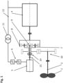
- Fig.2 shows an embodiment of a differential system according to the invention, which enables a supersynchronous working speed range without an adaptation gear.
- This embodiment is preferably used in high-speed working machines.
- the drive train shown here also has Fig.1 a working machine 1, a drive shaft 2, a drive machine 4 and a differential drive 5, which are connected to the drives of a differential gear 3.
- the differential drive 5 is connected to a network 12 by means of a converter 6 (consisting preferably of a motor-side and a network-side rectifier or inverter - shown here in a simplified form as a unit) and a transformer 11.
- the drive machine 4 can be connected to the network 12 by means of a switch 23.
- the drive shaft 2 is connected to the sun gear 13 and the drive machine 4 is connected to the ring gear 14 by means of a connecting shaft 19.
- the differential drive 5 can be connected to the planet carrier 16 with two or more planet gears 15. This makes it easy to achieve a gear ratio between the drive machine 4 and the working machine 1 of, for example, 2.5 to 6.5 using a planetary gear stage and without an adaptation gear. With, for example, a stepped planetary gear set, even significantly higher gear ratios can be achieved.
- a stepped planetary gear set is characterized in that the planet gears 15 each have two gears that are connected to one another in a rotationally fixed manner and have different pitch circle diameters, with one gear interacting with the sun gear and the second gear interacting with the ring gear.
- a pump is shown as an example.
- the pump used here and in the However, the principles described in the following figures are also applicable to drives for working machines, such as compressors, fans and conveyor belts, mills, crushers, etc. or energy generation plants and the like.
- a pump As a fluid machine, a pump has a square torque curve, which is superimposed on the typical breakaway torques from the bearings of the drive train elements etc. when starting up. This means that when starting up, a torque of e.g. 10%-20% of the nominal torque of the working machine 1 must first be overcome. As the speed increases, the required drive torque then decreases (due to the elimination of the breakaway torque) and a torque increases in accordance with the working speed of the working machine 1 (approximately quadratically), which reaches the nominal torque at the nominal speed.
- the torque curve described is shown in a diagram in Fig. 2a shown as an example.
- the planet carrier 16 can, for example, be designed as a single piece or in multiple pieces with components connected to one another in a rotationally fixed manner. Since the torque on the planet carrier 16 is high, it is advantageous to implement, for example, a gear stage 17, 18 between the planet carrier 16 and the differential drive 5.
- a spur gear stage for example, is suitable for this, with the gear 17 being connected in a rotationally fixed manner to the planet carrier 16 and the gear 18 being connected to the differential drive 5.
- the gear stage can also be multi-stage, for example, or be designed as a toothed belt, chain drive, planetary stage or as an angular gear.
- a gear transmission that can be adjusted in stages or continuously can also be implemented.
- Fig.2 shows a differential drive 5 with a converter 6.
- several differential drives can drive the planet carrier 16, whereby the torque to be transmitted from the gear stage 17, 18 to these differential drives.
- the differential drives can be distributed evenly or asymmetrically over the circumference of the gear wheel 17.
- the differential drives are controlled by a common converter 6, with one differential drive then preferably acting as a so-called "master” and the other differential drive(s) as a so-called “slave”.
- the differential drives can also be controlled by several motor-side rectifiers or inverters individually or in groups, with these so-called motor-side rectifiers or inverters connected to the differential drives preferably having a common so-called mains-side rectifier or inverter connected via a DC intermediate circuit to the mains 12 via a transformer 11.
- auxiliary gear - as in Fig.2 shown.
- at least a second differential drive via planet carrier 16 and gear ratio 17, 18 drives the auxiliary transmission 20 in addition to the first differential drive 5. This means that only one auxiliary transmission 20 is required.
- An auxiliary gear 20 is connected to the connecting shaft 19 and subsequently to the drive machine 4 or the first drive of the differential system.
- This auxiliary gear 20 can be connected to the differential drive 5 by means of a clutch 22 and preferably also drives a lubricating oil pump 21.
- the clutch 22 can basically be positioned anywhere between the differential drive 5 and the first drive of the differential system - i.e. also in a stage of the auxiliary gear 20 other than the one closest to the differential drive 5.
- the clutch 22 is preferably designed as a claw clutch, tooth clutch, multi-disk clutch or as a freewheel.
- a freewheel (also referred to as an overrunning clutch) is a clutch that only works in one direction of rotation. It can also be designed in the form of a self-synchronizing clutch. This is a freewheel in which the torque is transmitted via a tooth clutch.
- the drive machine 4 can also be equipped with a Gearbox intermediate stage of the auxiliary transmission 20, whereby the connection of the auxiliary transmission 20 with the first drive remains.
- the differential drive 5 is separably connected to the gear ratio 17, 18 via a clutch 25.
- the differential drive 5 is connected to the gear ratio 17, 18 by closing the clutch 25 and to the auxiliary gear 20 by closing the clutch 22.
- the clutch 22 is designed in the form of a freewheel, this automatically transfers the rotary motion of the differential drive 5 to the auxiliary gear 20 or the drive machine 4.
- the drive machine 4 is designed as an asynchronous machine, it is preferably brought to operating speed and then the switch 23 is closed and the drive machine 4 is connected to the network 12. When it is connected to the network 12, it only draws a magnetizing current for a short time. Although this is higher than the nominal current of the drive machine 4, it is only present for a few network periods and is far below the current that the drive machine 4 would draw if it were connected to the network under load. If necessary, this magnetizing current can be further reduced by using various recognized technical methods. The clutch 22 is then opened and the differential system works in the so-called differential mode.
- the connection is automatically released as soon as the speed of the driving part (differential drive 5) is lower than the speed of the part to be driven (in Fig.2 Auxiliary gear 20) (see also Fig.4 ).
- the drive machine 4 is designed as a synchronous machine, it can be synchronized with the network in accordance with the recognized rules of technology and thus connected to the network without any impact.
- the differential drive 5 helps to synchronize the drive machine 4 with the network by regulating the speed and preferably also the phase angle of the drive machine 4 and synchronizing it with the network 12.
- the drive engine 4 is an internal combustion engine, it can be started with the assistance of the differential drive 5.
- a brake 26 can be used which acts on the second drive of the differential system and/or a brake 27 which acts directly on the differential drive 5.
- An alternative solution is to open the clutch 25 and thereby separate the differential drive 5 from the rest of the differential system.
- the clutch 22 is designed as a freewheel, its connection is automatically activated as soon as the speed of the driving part (auxiliary gear 20) becomes lower than the speed of the part to be driven (differential drive 5), whereby an overspeed of the differential drive 5 is automatically prevented.
- the clutch 22 is designed as a multi-disk clutch, it is preferably activated in the event of a malfunction when the speed difference between the output shaft of the auxiliary transmission 20 and the differential drive 5 is a minimum (ideally at a speed difference of approximately zero).
- the brake 26 can also be used to brake the second drive of the differential system during the described starting process in order to prevent the planet carrier 16 from running up at the same time.
- the clutch 22 remains closed and the clutch 25 remains open. This allows the working machine 1 to be operated from a working speed of zero.
- the maximum achievable drive power for the working machine 1 is, however, limited in accordance with the power capacity of the Differential drive 5 is limited.
- the operation of a boiler water feed pump for example, also includes operating modes with low speed (lower than the achievable working speed in differential mode) and low power or also maintenance-related commissioning, these can be implemented using this embodiment.
- a similar result can be achieved by using a brake to stop the first drive (in the case of Fig.2 for example with a brake 28 on the drive machine 4).
- the clutch 25 is closed and the clutch 22 is opened. This allows the planet carrier 16 and subsequently the working machine 1 to be driven with the differential drive 5 when the ring gear 14 is stationary.
- Another application for such a brake 28 is to decelerate the drive machine 4 parallel to the working machine 1 in the event of a malfunction in order to prevent an overspeed on the differential drive 5.
- Fig.1 and Fig.2 show, in a differential system the first and second drive and the output can alternatively be connected to a ring gear or a planet carrier or a sun gear.
- the differential drive 5 is connected to the ring gear 14, the drive machine 4 to the planet carrier 16 and the working machine 1 to the sun gear 13.
- Other alternative combinations are also covered by the invention.
- the Fig.2 The configuration shown shows an embodiment with which high speeds can be achieved on the working machine 1 in a simple and cost-effective manner.
- An exemplary configuration in which the working machine 1 is connected to the ring gear 14, the drive machine 4 to the sun gear 13 and the differential drive 5 to the planet carrier 16 is a possible design variant for slow gear ratios.
- Fig.3 shows a further embodiment of a differential system for high-speed drives according to the invention.
- the differential system is basically constructed in the same way as in Fig.2 described.
- the gear ratio 29 is shown as a bevel gear stage.
- This means that the axis of rotation of the differential drive 5 is offset from the axis of rotation by Drive machine 4 and working machine 1 are arranged.
- This means that an auxiliary gear 30 is also designed as an angular gear.
- the angular offset increases the center distance between the differential drive 5 and working machine 1, allowing working machine 1 to move closer to the differential system.
- the differential drive 5 can also be arranged in a mirror image in the direction of drive machine 4 (see. Fig.2 and Fig.5 ) and thus move the drive machine 4 closer to the differential system.
- the auxiliary transmission 30, like the auxiliary transmission 20, is preferably designed such that (a) the direction of rotation of the working machine 1 and the drive machine 4 is opposite and (b) the drive machine 4 preferably reaches its operating speed as soon as the differential drive 5 comes into the region of its power limit.
- the auxiliary transmission 30 can be connected to the differential drive 5 by means of a clutch 31 and preferably also drives a lubricating oil pump 21.
- the clutch 31 can be positioned anywhere in the path between the differential drive 5 and the connecting shaft 19, but is preferably arranged between the lubricating oil pump 21 and the differential drive 5 in order to ensure emergency operation of the lubrication system. If the differential drive 5 is arranged in a mirror image in the direction of the drive machine 4, the first gear of the auxiliary transmission 30 runs, for example, in a coupling manner on the connecting shaft between the differential drive 5 and the second drive of the differential system (cf. Fig.2 and 5 ).
- clutch 31 The design and functions of clutch 31 are basically the same as for clutch 22.
- Clutch 22, 31 can also be designed as a hydrodynamic clutch/torque converter with an additional/integrated locking function and can therefore also be used as an emergency braking system by closing it as soon as an operational fault occurs in the drive train in differential mode and differential drive 5 is to be protected from overspeed (see corresponding explanations for Fig.2 ).
- a brake 27 can be used, which is directly connected to the Differential drive 5 can be used. In principle, however, any type of clutch can be used according to the invention.
- the coupling 34 shown serves primarily, like the couplings 32 and 33, to connect the working machine 1, the drive machine 4 and the differential drive 5 with the transmission part of the differential system.
- the coupling 34 can, as already mentioned, be Fig.2 described, can be designed to be releasable during operation (possibly also with automatic opening in the event of overspeed) in order to separate the differential drive 5 from the second drive of the differential system in the event of, for example, a malfunction.
- a freewheel can be used instead of the clutch 31, which prevents overspeed on the differential drive 5 in the event of a malfunction. This is made possible by the fact that in the event of a fault in differential mode (operating mode II), the speeds of the working machine 1 and the drive machine 4 always go in the direction of the "lowest working speed" and thus the required freewheel direction is defined accordingly.
- Phase 1 The differential drive 5 is connected to the second drive of the differential system and is additionally connected to the first drive (including connecting shaft 19 and drive machine 4) of the differential system by closing the clutch 31 by means of an auxiliary gear 30 (in the case of a freewheel, this is activated automatically).
- the differential drive 5 is then accelerated and the working machine 1 begins to work.
- a continuously variable working speed from zero to, for example, approx. 40%-50% of the nominal working speed of the working machine 1 can preferably be achieved in this operating mode I.
- the drive train is understood to mean the entire drive train between drive shaft 2 and drive motor 4. Drive motor 4 remains disconnected from the mains in this operating mode I.
- the gear ratios of the gears 3, 29 and 30 that are effective in this case are selected so that the drive machine 4 reaches its operating speed as soon as the differential drive 5 reaches its power limit.
- the differential drive 5 is designed so that it (a) can overcome the inherent breakaway torques of a drive train and (b) reaches a working speed in operating mode I that is in the range of the lowest possible working speed that can be achieved in differential mode (operating mode II).
- a more or less large overlap of the working speed ranges of operating modes I and II is allowed, among other things, in order to provide a control hysteresis for switching between operating modes I and II.
- a working speed gap can also be provided between operating modes I and II.
- torque and speed jumps must be accepted, which can preferably be compensated for by control technology or with dampers and/or clutches and/or hydrodynamic torque converters with an additional/integrated locking function - e.g. as clutch 31.
- the differential drive 5 cannot accelerate the drive machine 4 to its operating speed, as described above.
- the drive machine 4 is then connected to the network 12 at a speed lower than its synchronous speed, which leads to corresponding current and torque surges.
- the differential drive 5 operates as a motor - i.e. it draws energy from the mains.
- Phase 2 As soon as the drive motor 4 reaches its operating speed, it is, as already Fig.2 described, synchronized with the network 12 and the switch 23 closed.
- the differential drive 5 Since the differential drive 5 operates as a generator in the lower working speed range of operating mode II - i.e. it supplies energy to the grid, in the next step the torque of the differential drive 5 is regulated from the motor operation required for operating mode I to the generator operation initially required for operating mode II. This continuously increases the load on the drive machine 4 until the differential system preferably reaches the lower part of the working speed range of operating mode II.
- the transition from motor to generator operation of the differential drive is preferably dampened, i.e. not sudden.
- Phase 3 As soon as the differential system has reached the operating point described in phase 2 in the lower working speed range of operating mode II, the differential drive 5 is separated from the first drive of the differential system by either opening the clutch 31 or, in the case of a freewheel, the connection automatically releases (deactivates) as soon as the speed of the differential drive decreases.
- operating mode II differential mode
- the following procedure is preferably recommended: First, the lower part of the working speed range of operating mode II is controlled. After preferential synchronization of the both clutch halves (by means of speed control of the differential drive 5), the clutch 31 is closed (if not designed as a freewheel). In the next step, the torque of the differential drive 5 is regulated from the generator operation required for operating mode II to the motor operation required for operating mode I. This continuously relieves the load on the drive machine 4 until it no longer supplies any torque. By then opening the switch 23, the drive machine 4 can be smoothly disconnected from the network 12. If the clutch 22, 31 is designed as a freewheel, this activates itself. The differential system now works in operating mode I and can therefore be operated down to a working speed of zero.
- Fig.4 shows on a dimensionless time axis the course of torque and speed of the working machine 1, the drive machine 4, the differential drive 5 and the clutch 22, 31 during the Fig.3 described phases.
- Phase 1 At time T0 the complete differential system is at a standstill. As soon as the differential drive 5 starts to rotate, the working machine 1 and the drive machine 4 also accelerate until the latter reaches its operating speed - in Fig.4 marked with T1. Between the time markings T0 and T1 the differential system operates in operating mode I.
- Phase 2 In the next step, the drive machine 4, which has been operating without load up to this point, is synchronized with the network 12 and the switch 23 is closed at time T2.
- the torque of the differential drive 5 is then regulated from motor to generator operation (the torque of the differential drive 5 changes direction).
- the drive machine 4 is continuously subjected to a higher load (the torque of the drive machine 4 increases) until the differential system preferably reaches one of the lower operating points of the working speed range of operating mode II.
- the new Load distribution in the differential system regulates the torque originally flowing through the clutch 22, 31 towards zero and the clutch 22, 31 is opened or deactivated automatically in the case of freewheeling. Phase 2 is thus completed at time T4.
- the speeds for the input and output drives of the differential system preferably remain essentially constant in phase 2, but can also vary due to operational requirements of the working machine 1 or the synchronization process of the drive machine 4.
- an overlap of the working speeds of operating modes I and II is advantageous, since this allows any speed fluctuations occurring between times T1 and T2 to be regulated and thus the drive machine 4 can be connected to the network 12 without any impact.
- the area between T4 and T5 shows a partial load range in which the system power is variably regulated until it remains between T5 and T6, for example, at rated power with constant rated torque and constant rated speed (in Fig.4 therefore shown as a constant line).
- the differential drive 5 changes from generator to motor operation, which is visible in its speed (“differential drive" speed).
- the speed of the drive machine 4 (speed of the drive machine) remains essentially constant in operating mode II in the case of a three-phase machine.
- the clutch 22 or 31 is designed as a freewheel, the activation/deactivation of the clutch 22, 31 takes place automatically, which enables a smooth transition between the described phases/operating modes.
- the temporal relations of the time axis in Fig.4 can be individually designed and are based on the design criteria of the differential system or the operational requirements.
- the operating concept described also applies analogously to the generator operation of, for example, an energy generation plant.
- the working machine 1 is, for example, a wind power plant or a water turbine and the drive machine 4 is an electrical machine that essentially operates in generator mode.
- the power flow in the entire drive train rotates in comparison to the representations in the Fig. 1 to 12 or their description.
- the system according to the invention can be used to implement both a generator (turbine) and a motor (pump) operation, whereby it is possible to switch continuously from one operating mode to the other.
- the transition from one operating mode (turbine) to the other (pump) preferably takes place at time T0.
- the concept described here is also applicable in accordance with the Fig. 2 to 12 described functions and design variants can be expanded.
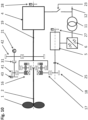
- Fig.5 shows an embodiment of a differential system according to the invention for preferably slow-running drives.
- the principle is derived from the explanations of Fig.1 , 2 and 3 and can also be used for high-speed drives.
- the main difference to the concept according to Fig.2 and 3 is that the differential drive 5 with the sun gear 9 as the second drive of the differential system (instead of the planet carrier 16 in Fig. 2 and 3 ) and the working machine 1 with the planet carrier 7 (instead of the sun gear 13 in Fig. 2 and 3 ).
- the differential drive 5 can be connected to the auxiliary transmission 20 by means of a clutch 22 and preferably also drives a lubricating oil pump 21.
- the clutch 22 can be positioned anywhere in the path between the differential drive 5 and the connecting shaft 19, but is preferably arranged between the lubricating oil pump 21 and the differential drive 5 in order to ensure emergency operation of the lubrication system.
- Fig.6 shows a further embodiment according to the invention in which a differential drive 5 can be connected to the second drive and the output of a differential system.
- the differential drive 5 is connected on the one hand to the second drive of the differential system and on the other hand can be connected by means of a clutch 22 and via an auxiliary gear 61 to the output of the differential system or the drive shaft 2.
- the differential drive 5 drives both the drive shaft 2 and the drive motor 4 via the planet carrier 7 and the ring gear 8.
- An adaptation gear stage 60 is in Fig.6 to optimize the speed control range of the differential drive 5.
- Fig.7 shows a further embodiment according to the invention, in which a differential drive 5 of a differential system is connected to the second drive and can be connected to the output.
- the second drive is connected to a ring gear 63, the first drive to a planet carrier 64 and the output to a sun gear 65.
- the differential drive 5 controls the speed of the drive shaft 2 via a gear ratio 66 and the externally toothed ring gear 63.
- the differential drive 5 can be connected to the output of the differential system by means of a clutch 31 and an auxiliary gear 62.
- a brake 67 is provided (symbolically shown as a disc brake in the embodiment shown), which is positioned in the area of the output shaft of the drive machine 4, with the brake shoes being connected to the drive machine 4. and the brake disk are preferably connected to the clutch 33.
- the clutch 33 is designed with an overload protection (e.g. torque limiter), it is preferable to ensure that this overload protection is not located in the main load path of the braking torque in order not to limit the maximum transferable braking torque.
- the main load path is the path through which the majority of the braking torque of the brake 67 flows.
- Fig.8 shows a further embodiment according to the invention in which a differential drive 5 of a differential system is connected to the second drive via an externally toothed ring gear 63 and can be connected to the first drive via clutch 22 and auxiliary gear 68.
- the embodiments according to Fig.6 , 7 and 8 are particularly suitable for use in energy generation plants such as wind turbines as working machine 1.
- the drive machine 4 is an electrical machine that essentially works in generator mode.
- the differential system is preferably part of a so-called main transmission, with the drive shaft 2 in most cases being connected to further gear stages of this main transmission in order to achieve a low speed required for the working machine with a correspondingly high torque.
- Fig.9 shows a further embodiment according to the invention, in which the output can be connected to the first drive of a differential system.
- the differential drive 5 is connected to the second drive and on the other hand, the output of the differential system or, for example, the drive shaft 2 can be connected via an auxiliary gear 70 by means of a clutch 31 to the first drive of the differential system or, subsequently, to the drive machine 4.
- the differential drive 5 in the In operating mode I the drive motor 4 is additionally driven via the output of the differential system or, in the embodiment shown, via the drive shaft 2.
- Fig.10 shows a further embodiment according to the invention in which the differential drive 5 can be connected to the first drive of the differential system via the second drive, a transmission gear 41 and an auxiliary gear 42.
- Fig. 11 shows an embodiment of the differential system according to the invention with a so-called plus gear (also referred to as epicyclic gear).
- the drive shaft 19 of the first drive of the differential system is connected to a first sun gear 44 and the working machine 1 to a second sun gear 45.
- a planet carrier 46 is equipped with two or more stepped planets 47, 48. Stepped planets are characterized in that the planet wheels each have two gears 47, 48 which are connected to one another in a rotationally fixed manner and have different pitch circle diameters.
- the gear 48 works together with the sun gear 44 and the gear 47 works together with the sun gear 45.
- the differential drive 5 drives the planet carrier 46 at a variable speed.
- the planet carrier 46 can be connected to the first drive of the differential system or the drive machine 4 via a transmission stage 49 and an auxiliary gear 50.
- the directions of rotation of the drive machine 4 and the working machine 1 are the same here and the gear stage 49, in combination with the auxiliary gear 50, reverses the direction of rotation relative to the planet carrier 46.
- the shown embodiment of a differential system in the form of a positive gear allows small gear ratios between the drive machine 4 and the working machine 1 and is also cost-effective to produce due to the lack of ring gears.
- Fig. 12 shows a further embodiment of the differential system according to the invention in the form of a positive gear. Basically, its function is derived from the explanations for Fig. 11 In this embodiment, however, the auxiliary gear 52 can be connected to the transmission gear 51. In a further In the embodiment according to the invention, the differential drive 5 is connected directly to the shaft 55.
- Fig. 2 to 12 there are a number of possibilities according to the invention for implementing the function of starting according to the invention. Basically, it is always a matter of bridging the differential system, e.g. by means of an auxiliary gear 20, 30, 42, 50, 52, 53, 61, 62, 68, 70, so that the drive machine 4 reaches its operating speed as soon as the work machine 1 reaches a lower working speed in operating mode II.
- auxiliary gear 20 e.g. by means of an auxiliary gear 20, 30, 42, 50, 52, 53, 61, 62, 68, 70
- the drive machine 4 reaches its operating speed as soon as the work machine 1 reaches a lower working speed in operating mode II.
- the drive machine 4 and work machine 1 are started up in parallel by means of a differential drive 5.
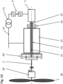
- Fig. 13 shows a further embodiment of a differential system for an energy generation plant according to the invention. If the system according to the invention is used in an energy generation plant, the drive machine 42 is an electrical machine that essentially operates in generator mode - preferably a separately excited medium-voltage synchronous machine. (see also explanations of Fig.4 and 8th ).
- the working machine 38 (e.g. the rotor of a wind turbine) drives the planet carrier of a differential stage 40 via the main gear 39.
- the Fig. 1 to 12 The drive machine described is thus operated as a generator 42 in the working operating range.
- a differential drive 5 connected to the network 12 via the converter 6 and the transformer 11 is connected to the second drive of the differential gear 40 by means of the shaft 35 (which is guided coaxially in a hollow rotor shaft 43 of the generator 42).
- the differential drive 5 can be connected to the rotor shaft 43 of the drive machine 42 by means of an auxiliary gear 53 and the coupling 54, wherein the planet carrier of the auxiliary gear 53 is connected to the housing of the generator 42 in a rotationally fixed manner or is integrated into it.
- the design of the coupling 54 is as follows: basically the same as for the clutch 22, 31.
- the auxiliary gear 53 shown schematically as a planetary stage, can also be replaced by one or more spur gear or bevel gear stages. This applies in particular if, according to AT 511 720 A the differential system is designed with several differential drives connected via a spur gear stage. In principle, however, any type of gear or belt drive or the like can be used.
- a hydrostatic actuator can be used instead of the differential drive 5, a hydrostatic actuator can be used.
- the differential drive 5 and the converter 6 are replaced by a two-part or multi-part hydrostatic pump/motor combination, which is connected to a pressure line and preferably has an adjustable flow volume. This means that the speeds can be regulated, as in the case of a variable-speed electric differential drive.
- Part of the pump/motor combination is preferably connected to the drive shaft 2 and/or at least temporarily to the network 12 by means of an electric drive, and/or part of the pump/motor combination is temporarily driven by another drive unit.
- This design variant can also be used analogously when using a hydrodynamic torque converter as a differential drive.
- the system according to the invention can also be used to operate the drive machine 4 or the generator 42 in what is known as phase shifting operation.
- the drive machine can supply or draw reactive power into or from the network 12 either as a motor 4 or as a generator 42 without the working machine 1 being operated.
- the drive machine 4 or 42 is preferably only synchronized and connected to the network 12 by means of a differential drive 5 and then the differential drive 5 is separated from the drive machine 4, 42, preferably by opening the clutch 22, 31, 54, without carrying out the further steps of the described start-up process. This only takes place when the working machine 1 is to start operation.
Landscapes
- Engineering & Computer Science (AREA)
- Mechanical Engineering (AREA)
- Chemical & Material Sciences (AREA)
- Combustion & Propulsion (AREA)
- General Engineering & Computer Science (AREA)
- Transportation (AREA)
- Power Engineering (AREA)
- Life Sciences & Earth Sciences (AREA)
- Sustainable Energy (AREA)
- Sustainable Development (AREA)
- Structure Of Transmissions (AREA)
- Retarders (AREA)
- Control Of Multiple Motors (AREA)
- Arrangement Of Transmissions (AREA)
- Electric Propulsion And Braking For Vehicles (AREA)
- Hybrid Electric Vehicles (AREA)
- Auxiliary Drives, Propulsion Controls, And Safety Devices (AREA)
Abstract
Zum Anfahren eines Triebstranges mit einer Antriebswelle (2) einer Arbeitsmaschine (1), mit einer Antriebsmaschine (4, 42) und mit einem Differenzialgetriebe (3, 7 bis 9, 40) mit drei An- bzw. Abtrieben, wobei ein Abtrieb mit der Antriebswelle (2), ein erster Antrieb mit der Antriebsmaschine (4, 42) und ein zweiter Antrieb mit einem Differenzialantrieb (5) verbindbar ist, wird die Antriebsmaschine (4, 42) von einer Drehzahl von Null oder annähernd Null angefahren, während der Differenzialantrieb (5) gleichzeitig mit dem ersten und dem zweiten Antrieb verbunden ist.
Description
- Die Erfindung betrifft einen Triebstrang mit den Merkmalen des Oberbegriffs des Anspruchs 1.
- Die Erfindung betrifft des Weiteren ein Verfahren zum Anfahren eines Triebstranges mit den Merkmalen des Oberbegriffs von Anspruch 25.
- Ein allgemeines Problem von Arbeitsmaschinen, wie Fördereinrichtungen, z.B. Pumpen, Kompressoren und Ventilatoren, oder wie Mühlen, Brecher, Fahrzeuge usw., ist ein effizienter, drehzahlvariabler Betrieb, bzw. das Anfahren unter Last, bzw. der Betrieb von z.B. Energiegewinnungsanlagen bis zu einer Drehzahl gleich Null. Im Weiteren werden elektrische Maschinen als Beispiel für Antriebsmaschinen bzw. Generatoren herangezogen, das Prinzip gilt aber für alle möglichen Arten von Antriebsmaschinen, so wie z.B. für Verbrennungskraftmaschinen.
- Die heute am häufigsten verwendeten elektrischen Antriebe bzw. Generatoren sind Drehstrommaschinen, wie z.B. Asynchronmaschinen und Synchronmaschinen, welche im Wesentlichen nur mit konstanter Drehzahl betrieben werden. Es muss darüber hinaus eine Drehstrommaschine und ein dieser nachgelagertes Stromnetz entsprechend groß ausgelegt werden, damit sie vom Stillstand weg ein erforderliches Antriebsmoment liefern kann. Elektrische Maschinen werden daher auch aus diesem Grund, anstatt direkt an ein Netz angeschlossen zu werden, häufig in Kombination mit einem Frequenzumrichter als drehzahlvariabler Antrieb ausgeführt. Damit kann man zwar einen drehzahlvariablen Betrieb von Drehzahl Null realisieren, ohne das Netz stark zu belasten, die Lösung ist jedoch teuer und mit wesentlichen Wirkungsgradeinbußen verbunden. Eine im Vergleich dazu kostengünstigere und auch bezüglich Wirkungsgrad bessere Alternative ist der Einsatz von Differenzialsystemen - beispielsweise gemäß
AT 507 394 A - Um dies zu realisieren, gibt es verschiedene Möglichkeiten. Gemäß
DE 20 2012 101 708 U beispielsweise kann man das Übersetzungsverhältnis des Differenzialgetriebes auf 1 festlegen. Auf dieser Basis kann man mit dem Differenzialantrieb den kompletten Triebstrang antreiben bzw. die Antriebsmaschine auf Synchrondrehzahl bringen und diese in weiterer Folge mit dem Netz synchronisieren. - Nachteil dieser Lösung ist, dass der Differenzialantrieb und der ihm nachgelagerte Frequenzumrichter wesentlich kleiner dimensioniert sind als die Antriebsmaschine und daher auch nur ein entsprechend kleines Drehmoment liefern können. Dies reicht nicht aus, die Antriebsmaschine bis zur Synchrondrehzahl zu beschleunigen, wenn die Arbeitsmaschine in Betrieb ist.
- Die
AT 514 396 A - Aufgabe der Erfindung ist es daher, eine Lösung zu finden, mit der man Antriebsmaschinen vorzugsweise unter Last beschleunigen kann, beispielsweise um z.B. direkt an ein Netz gekoppelte, elektrische Maschinen mit dem Netz zu synchronisieren, bzw. einen großen Arbeitsdrehzahlbereich realisieren kann.
- Gelöst wir diese Aufgabe mit einem Triebstrang mit den Merkmalen des Anspruchs 1.
- Gelöst wird diese Aufgabe des Weiteren mit einem Verfahren mit den Merkmalen des Anspruchs 25.
- Der Kern eines Differenzialsystems ist ein Differenzialgetriebe, das in einer einfachen Ausführung eine einfache Planetengetriebestufe mit drei An- bzw. Abtrieben sein kann, wobei ein Abtrieb mit der Antriebswelle einer Arbeitsmaschine, ein erster Antrieb mit einer Antriebsmaschine und ein zweiter Antrieb mit einem Differenzialantrieb verbunden ist. Damit kann die Arbeitsmaschine bei konstanter Drehzahl der Antriebsmaschine drehzahlvariabel betrieben werden, wobei der Differenzialantrieb eine variable Drehzahl der Antriebswelle ermöglicht.
- Um eine Arbeitsmaschine vom Stillstand aus in Betrieb zu setzen und, wenn die Antriebsmaschine eine elektrische Maschine ist, zusätzlich eine Antriebsmaschine vom Stillstand aus vorzugsweise auf Synchrondrehzahl zu bringen, kann der Betrieb des Systems erfindungsgemäß z.B. in den folgenden 3 Phasen stattfinden:
- Phase 1: Ein Differenzialantrieb wird im Stillstand sowohl mit dem ersten Antrieb als auch mit dem zweiten Antrieb des Differenzialsystems verbunden. Anschließend wird der Differenzialantrieb beschleunigt und die Arbeitsmaschine beginnt zu arbeiten. Abhängig von der Drehmomentkennlinie der Arbeitsmaschine und der Leistung des Differenzialantriebes, wird in diesem Betriebsmodus I vorzugsweise ein Arbeitsdrehzahlbereich von bis zu ca. 40%-50% der Arbeits-Nenndrehzahl der Arbeitsmaschine realisiert. Die Antriebsmaschine bleibt in diesem Betriebsmodus I vom Netz getrennt. Die Übersetzungsverhältnisse der Getriebestufen, über welche der Differenzialantrieb mit den beiden Antrieben verbunden ist, werden vorzugsweise so gewählt, dass die Antriebsmaschine zumindest annähernd ihre Betriebsdrehzahl erreicht, sobald der Differenzialantrieb in die Nähe seiner Leistungsgrenze kommt. Der Differenzialantrieb arbeitet in dieser Phase motorisch - d.h. er bezieht Energie vom Netz.
- Phase 2: Die mit dem ersten Antrieb des Differenzialsystems verbundene und jetzt im Betriebsdrehzahlbereich laufende Antriebsmaschine wird nun mit dem Netz verbunden. Da der Differenzialantrieb im unteren Arbeitsdrehzahlbereich des Betriebsmodus II generatorisch arbeitet - d.h. er liefert Energie ins Netz, wird im nächsten Schritt das Drehmoment des Differenzialantriebes vom motorischen in den generatorischen Betrieb geregelt. Dadurch wird die Antriebsmaschine kontinuierlich immer stärker belastet, bis das gesamte Differenzialsystem vorzugsweise in den Bereich der unteren Grenze des Arbeitsdrehzahlbereiches des Betriebsmodus II kommt.
Um die Systembelastungen möglichst gering zu halten, erfolgt vorzugsweise der Übergang vom motorischen in den generatorischen Betrieb des Differenzialantriebes gedämpft, d.h. nicht schlagartig. - Phase 3: Sobald sich am Differenzialantrieb und an der Antriebsmaschine bezüglich Drehzahl und Drehmoment ein Betriebspunkt im unteren Arbeitsdrehzahlbereich des Betriebsmodus II eingestellt hat, wird der Differenzialantrieb vom ersten Antrieb des Differenzialsystems getrennt. Das System arbeitet nun im Differenzialmodus, womit in dieser dritten Phase für die Arbeitsmaschine ein maximales Drehmoment bei maximaler Antriebsdrehzahl realisiert werden kann.
- Bevorzugte Ausführungsformen der Erfindung sind Gegenstand der Unteransprüche.
- Nachfolgend werden bevorzugte Ausführungsformen der Erfindung mit Bezug auf die angeschlossenen Zeichnungen erläutert. Es zeigt:
- Fig. 1
- das Prinzip eines Differenzialsystems für einen Antrieb einer Pumpe gemäß Stand der Technik,
- Fig. 2
- eine erfindungsgemäße Ausführungsform eines Differenzialsystems für schnell laufende Antriebe,
- Fig. 2a
- ein Diagramm mit einem typischen Drehmomentverlauf einer Pumpe,
- Fig. 3
- eine weitere erfindungsgemäße Ausführungsform eines Differenzialsystems für schnell laufende Antriebe,
- Fig. 4
- einen zeitlichen Verlauf von Drehzahl- und Leistungsparameter eines Differenzialsystems während des Anfahrens,
- Fig. 5
- eine erfindungsgemäße Ausführungsform eines Differenzialsystems für langsam laufende Antriebe,
- Fig. 6
- eine weitere erfindungsgemäße Ausführungsform, in der ein Differenzialantrieb mit einem zweiten Antrieb und einem Abtrieb eines Differenzialsystems verbindbar ist,
- Fig. 7
- eine weitere erfindungsgemäße Ausführungsform, in der ein Differenzialantrieb 5 eines Differenzialsystems mit dem zweiten Antrieb verbunden und dem Abtrieb verbindbar ist,
- Fig. 8
- eine weitere erfindungsgemäße Ausführungsform, in der ein Differenzialantrieb 5 eines Differenzialsystems mit dem zweiten Antrieb verbunden und dem Abtrieb verbindbar ist,
- Fig. 9
- eine weitere erfindungsgemäße Ausführungsform, in der ein Abtrieb mit einem ersten Antrieb eines Differenzialsystems verbindbar ist,
- Fig. 10
- eine weitere erfindungsgemäße Ausführungsform, in der ein Differenzialantrieb via eines zweiten Antriebs mit einem ersten Antrieb eines Differenzialsystems verbindbar ist,
- Fig. 11
- eine erfindungsgemäße Ausführungsform eines Differenzialsystems mit einem Plusgetriebe,
- Fig. 12
- eine weitere erfindungsgemäße Ausführungsform eines Differenzialsystems mit einem Plusgetriebe, und
- Fig. 13
- eine weitere erfindungsgemäße Ausführungsform eines Differenzialsystems für eine Energiegewinnungsanlage.
-
Fig. 1 zeigt das Prinzip eines Differenzialsystems für einen Triebstrang am Beispiel einer Pumpe. Dabei ist die Arbeitsmaschine 1 der symbolisch dargestellte Rotor einer Pumpe, welcher über eine Antriebswelle 2 und ein Differenzialgetriebe 7 bis 9 von einer Antriebsmaschine 4 angetrieben wird. Die Antriebsmaschine 4 ist vorzugsweise eine Mittelspannungs-Drehstrommaschine, welche an ein Netz 12, welches im gezeigten Beispiel aufgrund einer Mittelspannungs-Drehstrommaschine ein Mittelspannungsnetz ist, angeschlossen wird. Das gewählte Spannungsniveau hängt vom Einsatzfall und vor allem dem Leistungsniveau der Antriebsmaschine 4 ab und kann ohne Einfluss auf die Grundfunktion des erfindungsgemäßen Systems jedes gewünschte Spannungsniveau haben. Entsprechend der Polpaarzahl der Antriebsmaschine 4 ergibt sich ein bauartspezifischer Betriebsdrehzahlbereich. Der Betriebsdrehzahlbereich ist dabei jener Drehzahlbereich, in dem die Antriebsmaschine 4 ein definiertes bzw. gewünschtes oder erforderliches Drehmoment liefern kann, und in dem die Antriebsmaschine 4 im Falle einer elektrischen Antriebsmaschine mit dem Netz 12 synchronisiert werden, bzw. im Falle einer Verbrennungskraftmaschine gestartet bzw. betrieben werden kann. Ein Planetenträger 7 des Differenzialgetriebes ist mit der Antriebswelle 2 verbunden, die Antriebsmaschine 4 mit einem Hohlrad 8 und ein Sonnenrad 9 des Differenzialgetriebes mit einem Differenzialantrieb 5. Der Differenzialantrieb 5 ist vorzugsweise eine Drehstrommaschine und insbesondere eine Asynchronmaschine oder eine permanentmagneterregte Synchronmaschine. - Anstelle des Differenzialantriebes 5 kann auch ein hydrostatisches Stellgetriebe eingesetzt werden. Dabei wird der Differenzialantrieb 5 durch eine hydrostatische Pumpe/Motor-Kombination ersetzt, welche mit einer Druckleitung verbunden und welche beide vorzugsweise im Durchflussvolumen verstellbar sind. Damit sind wie im Falle eines drehzahlvariablen, elektrischen Differenzialantriebes 5 die Drehzahlen regelbar.
- Der Kern des Differenzialsystems ist in dieser Ausführungsform somit eine einfache Planetengetriebestufe mit drei An- bzw. Abtrieben, wobei ein Abtrieb mit der Antriebswelle 2 der Arbeitsmaschine 1, ein erster Antrieb mit der Antriebsmaschine 4 und ein zweiter Antrieb mit dem Differenzialantrieb 5 verbunden ist.
- Um den Drehzahlbereich des Systems optimal anpassen zu können, wird ein Anpassungsgetriebe 10 zwischen dem Planetenträger 7 und der Arbeitsmaschine 1 implementiert. Alternativ zur gezeigten Stirnradstufe kann das Anpassungsgetriebe 10 beispielsweise auch mehrstufig sein bzw. als Zahnriemen oder Kettentrieb ausgeführt und/oder mit einer Planetengetriebestufe oder einer Kegelradstufe kombiniert werden. Mit dem Anpassungsgetriebe 10 kann man darüber hinaus einen Achsversatz für die Arbeitsmaschine 1 realisieren, der eine koaxiale Anordnung des Differenzialantriebes 5 und der Antriebsmaschine 4 ermöglicht. Elektrisch ist der Differenzialantrieb 5 mittels vorzugsweise einem Niederspannungs-Umrichter 6 und - sofern erforderlich - einem Transformator 11 an das Netz 12 angebunden. Wesentlicher Vorteil dieses Konzeptes ist, dass die Antriebsmaschine 4 direkt, das heißt ohne aufwändige Leistungselektronik, an das Netz 12 angebunden werden kann. Der Ausgleich zwischen variabler Rotordrehzahl und fixer Drehzahl der netzgebundenen Antriebsmaschine 4 wird durch den drehzahlvariablen Differenzialantrieb 5 realisiert.
- Die Drehmomentgleichung für das Differenzialsystem lautet:

- Der Größenfaktor y/x ist ein Maß für die Übersetzungsverhältnisse im Differenzialgetriebe 3 und im Anpassungsgetriebe 10. Das Drehmoment an den Ab- und Antrieben ist zueinander proportional, wodurch der Differenzialantrieb 5 das Drehmoment im gesamten Triebstrang regeln kann. Die Leistung des Differenzialantriebs 5 ist im Wesentlichen proportional dem Produkt aus prozentueller Abweichung der Drehzahl der Arbeitsmaschine 1 von deren Grunddrehzahl, multipliziert mit der Antriebswellenleistung. Die Grunddrehzahl ist dabei jene Drehzahl, welche sich an der Arbeitsmaschine 1 einstellt, wenn der Differenzialantrieb 5 die Drehzahl gleich Null hat. Dementsprechend erfordert ein großer Arbeitsdrehzahlbereich der Arbeitsmaschine 1 eine entsprechend große Dimensionierung des Differenzialantriebes 5. Hat der Differenzialantrieb 5 beispielsweise eine Nennleistung von rund 20% der System-Gesamtleistung (Nennleistung der Arbeitsmaschine), bedeutet dies unter Ausnutzung eines typischen sogenannten Feldschwächebereichs des Differenzialantriebes 5, dass an der Arbeitsmaschine 1 minimale Arbeitsdrehzahlen von etwa 50% der Arbeits-Nenndrehzahl realisiert werden können. Darin ist auch der Grund zu sehen, warum Differenzialsysteme gemäß Stand der Technik für kleine Arbeitsdrehzahlbereiche besonders gut geeignet sind, wobei aber grundsätzlich jeder Arbeitsdrehzahlbereich realisierbar ist. Es kann jedoch festgestellt werden, dass höherpolige Drehstrommaschinen standardmäßig meist höhere Überdrehzahlen in Relation zur Synchrondrehzahl erlauben, was prinzipiell einen (bei gleicher Nennleistung des Differenzialantriebes 5) größeren Arbeitsdrehzahlbereich der Arbeitsmaschine 1 ermöglicht, weil ein größerer Feldschwächebereich des Differenzialantriebes 5 möglich ist.
- Um das Differenzialsystem von einer Drehzahl gleich Null anfahren zu können, wird der Differenzialantrieb 5 mittels einer Kupplung 25 mit dem Sonnenrad 9 trennbar verbunden. Eine Synchronisationsbremse 24 wirkt auf den zweiten Antrieb des Differenzialsystems und somit auf das Sonnenrad 9 und damit auf den gesamten Triebstrang. Beim Anfahren wird in dieser Ausführungsform eines Differenzialsystems in einem ersten Schritt der Differenzialantrieb 5 durch die Kupplung 25 vom Rest des Differenzialsystems entkoppelt. Wird nun die Antriebsmaschine 4 hochgefahren und mit dem Netz 12 verbunden, so dreht das Sonnenrad 9 frei mit und es kann sich im gesamten Triebstrang kein nennenswertes Drehmoment aufbauen. Somit verbleibt auch in diesem Fall die Arbeitsmaschine 1 in einem Bereich kleiner Drehzahl und die Antriebsmaschine 4 kann ohne nennenswertes äußeres Gegenmoment mit dem Netz 12 verbunden werden.
- Sobald die Antriebsmaschine 4 über eine gewisse Drehzahl beschleunigt und die Arbeitsmaschine 1 im Wesentlichen still steht, stellt sich am Sonnenrad 9 eine entsprechend dem Übersetzungsverhältnis des Differenzialgetriebes hohe Drehzahl ein, welche meist über dem erlaubten Regeldrehzahlbereich des Differenzialantriebes 5 liegt. Der Regeldrehzahlbereich ist der Drehzahlbereich, in dem der Differenzialantrieb 5 arbeitet, um den Arbeitsdrehzahlbereich der Arbeitsmaschine 1 realisieren zu können. Der Regeldrehzahlbereich wird dabei vor allem durch die vom Hersteller spezifizierten Spannungs-, Strom- und Drehzahlgrenzen bestimmt.
- Der Differenzialantrieb 5 kann bei diesem Ausführungsbeispiel in dieser Phase nicht mit dem Sonnenrad 9 verbunden werden. In einem weiteren Schritt wird daher mittels Synchronisationsbremse 24 der mit dem Sonnenrad 9 verbundene zweite Antrieb des Differenzialsystems auf eine Drehzahl verzögert, welche im Regeldrehzahlbereich des Differenzialantriebes 5 liegt. Dies kann, abhängig vom realisierten Bremssystem 24 bzw. den Anforderungen an den Triebstrang, sowohl Drehzahl/Drehmoment-geregelt als auch -ungeregelt erfolgen. In weiterer Folge wird der differenzialgetriebeseitige Teil der Kupplung 25 vorzugsweise mittels Differenzialantrieb 5 mit der Drehzahl des zweiten Antriebs des Differenzialsystems synchronisiert und anschließend die Kupplung 25 geschlossen. Durch Betätigung der Synchronisationsbremse 24 (in
Fig. 1 symbolisch als hydrodynamische Bremse dargestellt) und damit Verzögerung des zweiten Antriebes des Differenzialsystems wird zwangsweise die Antriebswelle 2 beschleunigt, wobei das dazu zur Verfügung stehende Drehmoment durch das Minimum aus der auf die Antriebswelle 2 wirkenden Bremskraft der Synchronisationsbremse 24 einerseits und dem Kippmoment der Antriebsmaschine 4 andererseits bestimmt wird. -
Fig. 2 zeigt eine erfindungsgemäße Ausführungsform eines Differenzialsystems, welches einen übersynchronen Arbeitsdrehzahlbereich ohne Anpassungsgetriebe ermöglicht. Diese Ausführungsform kommt bevorzugt bei schnell laufenden Arbeitsmaschinen zum Einsatz. Der dargestellte Triebstrang weist auch hier wie inFig. 1 eine Arbeitsmaschine 1, eine Antriebswelle 2, eine Antriebsmaschine 4 und einen Differenzialantrieb 5 auf, welche mit den Ab- bzw. Antrieben eines Differenzialgetriebes 3 verbunden sind. Der Differenzialantrieb 5 ist mittels eines Umrichters 6 (bestehend aus vorzugsweise motorseitigem und netzseitigem Gleich- bzw. Wechselrichter - hier vereinfacht als Einheit dargestellt) und eines Transformators 11 an ein Netz 12 angeschlossen. Die Antriebsmaschine 4 ist mittels eines Schalters 23 mit dem Netz 12 verbindbar. - Da in dem ausgeführten Beispiel die Arbeitsmaschine 1 mit einer Drehzahl betrieben wird, die deutlich über der synchronen Drehzahl der Antriebsmaschine 4 liegt, wird die Antriebswelle 2 mit dem Sonnenrad 13 und die Antriebsmaschine 4 mittels einer Verbindungswelle 19 mit dem Hohlrad 14 verbunden. Der Differenzialantrieb 5 ist mit dem Planetenträger 16 mit zwei oder mehreren Planetenrädern 15 verbindbar. Damit kann man auf einfache Art mit einer Planetengetriebestufe und ohne Anpassungsgetriebe eine Übersetzung zwischen Antriebsmaschine 4 und Arbeitsmaschine 1 von beispielsweise 2,5 bis 6,5 erreichen. Mit beispielsweise einem Stufenplanetensatz sind darüber hinaus noch wesentlich höhere Übersetzungsverhältnisse erreichbar. Ein Stufenplanetensatz ist dadurch gekennzeichnet, dass die Planetenräder 15 jeweils zwei Zahnräder aufweisen, welche miteinander drehfest verbunden sind und unterschiedliche Teilkreisdurchmesser aufweisen, wobei ein Zahnrad mit dem Sonnenrad und das zweite Zahnrad mit dem Hohlrad zusammenwirkt.
- Als Arbeitsmaschine 1 ist in den
Figuren 1 bis 3 ,5 und9 bis 12 beispielhaft symbolisch eine Pumpe dargestellt. Die hier und zu den folgenden Figuren beschriebenen Prinzipien sind jedoch auch bei Antrieben für Arbeitsmaschinen, wie z.B. Kompressoren, Ventilatoren und Förderbänder, Mühlen, Brecher, etc. oder Energiegewinnungsanlagen und dergleichen anwendbar. - Eine Pumpe hat als Strömungsmaschine einen quadratischen Drehmomentverlauf, dem beim Anfahren bautypische Losbrechmomente aus der Lagerung der Triebstrangelemente etc. überlagert sind. Dies führt dazu, dass beim Anfahren zuerst ein Drehmoment in der Höhe von z.B. 10%-20% des Nenndrehmomentes der Arbeitsmaschine 1 zu überwinden ist. Mit steigender Drehzahl sinkt dann das erforderliche Antriebsdrehmoment (durch Wegfall des Losbrechmomentes) und es stellt sich ein entsprechend der Arbeitsdrehzahl der Arbeitsmaschine 1 (etwa quadratisch) ansteigendes Drehmoment ein, welches bei Nenndrehzahl das Nenndrehmoment erreicht. Der beschriebene Drehmomentverlauf ist in einem Diagramm in
Fig. 2a beispielhaft dargestellt. - Mit einer von der Antriebsmaschine 4 bestimmten Drehzahl des Hohlrades 14 und einer betriebsbedingt geforderten Drehzahl des Sonnenrades 13 ergibt sich zwangsläufig eine einzustellende Drehzahl bzw. ein einzustellendes Drehmoment am Planetenträger 16, welche vom Differenzialantrieb 5 zu regeln sind.
- Der Planetenträger 16 kann beispielsweise einteilig oder mehrteilig mit drehfest miteinander verbundenen Komponenten ausgeführt sein. Da das Drehmoment am Planetenträger 16 hoch ist, ist es von Vorteil, z.B. eine Übersetzungsstufe 17, 18 zwischen dem Planetenträger 16 und dem Differenzialantrieb 5 zu implementieren. Dafür bietet sich z.B. eine Stirnradstufe an, wobei das Zahnrad 17 drehfest mit dem Planetenträger 16 und das Zahnrad 18 mit dem Differenzialantrieb 5 verbunden ist. Alternativ kann die Übersetzungsstufe beispielsweise auch mehrstufig sein, bzw. als Zahnriemen, Kettentrieb, Planetenstufe oder als Winkelgetriebe ausgeführt werden. Anstelle der Übersetzungsstufe 17, 18 kann auch ein gegebenenfalls in Stufen oder stufenlos verstellbares Übersetzungsgetriebe implementiert werden.
-
Fig. 2 zeigt einen Differenzialantrieb 5 mit einem Umrichter 6. Ebenso können mehrere Differenzialantriebe den Planetenträger 16 antreiben, womit das zu übertragende Drehmoment der Übersetzungsstufe 17, 18 auf diese Differenzialantriebe verteilt wird. Die Differenzialantriebe können dabei gleichmäßig oder auch asymmetrisch über den Umfang des Zahnrades 17 verteilt sein. Vorzugsweise - jedoch nicht notwendigerweise - werden die Differenzialantriebe dabei von einem gemeinsamen Umrichter 6 angesteuert, wobei dann vorzugsweise ein Differenzialantrieb als sogenannter "Master" und der/die weitere(n) Differenzialantrieb(e) als sogenannter "Slave" fungieren. Die Differenzialantriebe können auch von mehreren motorseitigen Gleich- bzw. Wechselrichtern einzeln oder in Gruppen angesteuert werden, wobei diese mit den Differenzialantrieben verbundenen sogenannten motorseitigen Gleich- bzw. Wechselrichter vorzugsweise einen gemeinsamen, via Gleichstromzwischenkreis verbundenen, an das Netz 12 via Transformator 11 angeschlossenen sogenannten netzseitigen Gleich- bzw. Wechselrichter haben. - Wenn das System mit mehreren Differenzialantrieben ausgestattet ist, dann wird vorzugsweise nur ein Differenzialantrieb 5 über ein Hilfsgetriebe mit der Antriebsmaschine 4 verbunden - wie in
Fig. 2 gezeigt. In diesem Fall treibt zumindest ein zweiter Differenzialantrieb via Planetenträger 16 und Übersetzungsstufe 17, 18 das Hilfsgetriebe 20 zusätzlich zum ersten Differenzialantrieb 5 an. Damit ist nur ein Hilfsgetriebe 20 erforderlich. - Mit der Verbindungswelle 19 und in weiterer Folge mit der Antriebsmaschine 4 bzw. dem ersten Antrieb des Differenzialsystems ist ein Hilfsgetriebe 20 verbunden. Dieses Hilfsgetriebe 20 ist mittels einer Kupplung 22 mit dem Differenzialantrieb 5 verbindbar und treibt vorzugsweise auch eine Schmierölpumpe 21 an. Die Kupplung 22 kann grundsätzlich überall zwischen Differenzialantrieb 5 und dem ersten Antrieb des Differenzialsystems positioniert sein - d.h. auch in einer anderen als der dem Differenzialantrieb 5 nächstgelegenen Stufe des Hilfsgetriebes 20. Die Kupplung 22 ist vorzugsweise als Klauenkupplung, Zahnkupplung, Lamellenkupplung oder als Freilauf ausgeführt. Ein Freilauf (auch als Überholkupplung bezeichnet) ist dabei eine nur in eine Drehrichtung wirkende Kupplung. Er kann auch in Form einer selbstsynchronisierenden Schaltkupplung ausgeführt werden. Dies ist ein Freilauf, bei dem die Drehmomentübertragung über eine Zahnkupplung erfolgt. Die Antriebsmaschine 4 kann auch mit einer Getriebe-Zwischenstufe des Hilfsgetriebes 20 verbunden sein, wobei die Verbindung des Hilfsgetriebes 20 mit dem ersten Antrieb bestehen bleibt.
- Der Differenzialantrieb 5 ist in der gezeigten Ausführung über eine Kupplung 25 trennbar mit der Übersetzungsstufe 17, 18 verbunden. Um das System anzufahren, wird der Differenzialantrieb 5 durch Schließen der Kupplung 25 mit der Übersetzungsstufe 17, 18 und durch Schließen der Kupplung 22 mit dem Hilfsgetriebe 20 verbunden. Indem anschließend der Differenzialantrieb 5 hochgefahren wird, beschleunigen somit Arbeitsmaschine 1 und die Antriebsmaschine 4 gleichzeitig. Im Falle der Ausführung der Kupplung 22 in Form eines Freilaufes überträgt dieser selbsttätig die Drehbewegung des Differenzialantriebes 5 auf das Hilfsgetriebe 20 bzw. die Antriebsmaschine 4.
- Ist die Antriebsmaschine 4 als Asynchronmaschine ausgeführt, so wird diese vorzugsweise auf Betriebsdrehzahl gebracht und anschließend der Schalter 23 geschlossen und die Antriebsmaschine 4 mit dem Netz 12 verbunden. Diese zieht, wenn sie mit dem Netz 12 verbunden wird, nur kurzzeitig einen Magnetisierungsstrom. Dieser ist zwar höher als der Nennstrom der Antriebsmaschine 4, steht jedoch nur für wenige Netzperioden an und liegt weit unter dem sich einstellenden Strom, den die Antriebsmaschine 4 ziehen würde, wenn diese unter Last ans Netz geschaltet wird. Dieser Magnetisierungsstrom kann im Bedarfsfall durch Einsatz verschiedener anerkannter technischer Methoden zusätzlich reduziert werden. Anschließend wird die Kupplung 22 geöffnet und das Differenzialsystem arbeitet im sogenannten Differenzialmodus. Ist die Kupplung 22 als Freilauf ausgeführt, so wird die Verbindung selbsttätig gelöst, sobald die Drehzahl des treibenden Teils (Differenzialantrieb 5) kleiner als die Drehzahl des zu treibenden Teils (in
Fig. 2 Hilfsgetriebe 20) wird (vergl. hierzu auchFig. 4 ). Ist die Antriebsmaschine 4 als Synchronmaschine ausgeführt, so kann diese gemäß den anerkannten Regeln der Technik mit dem Netz synchronisiert und somit stoßfrei ans Netz geschaltet werden. Der Differenzialantrieb 5 hilft dabei, die Antriebsmaschine 4 mit dem Netz zu synchronisieren, indem dieser die Drehzahl und vorzugsweise auch den Phasenwinkel der Antriebsmaschine 4 regeln und mit dem Netz 12 synchronisieren kann. - Ist die Antriebsmaschine 4 eine Verbrennungskraftmaschine, so kann diese mit Unterstützung des Differenzialantriebes 5 gestartet werden.
- Im Falle einer Betriebsstörung (z.B. Netzausfall) würden im schlimmsten Fall sowohl die Antriebsmaschine 4 als auch die Arbeitsmaschine 1 unkontrolliert auslaufen. Um in einem solchen Fall den im Differenzialmodus arbeitenden Differenzialantrieb 5 vor Überdrehzahl zu schützen, kann man entweder eine Bremse 26, welche auf den zweiten Antrieb des Differenzialsystems wirkt und/oder eine Bremse 27, welche direkt auf den Differenzialantrieb 5 wirkt einsetzen. Als alternative Lösung bietet sich an, die Kupplung 25 zu öffnen und dadurch den Differenzialantrieb 5 vom restlichen Differenzialsystem zu trennen.
- Ist die Kupplung 22 als Freilauf ausgeführt, so wird dessen Verbindung selbsttätig aktiviert sobald die Drehzahl des treibenden Teils (Hilfsgetriebe 20) kleiner als die Drehzahl des zu treibenden Teils (Differenzialantrieb 5) wird, wodurch eine Überdrehzahl des Differenzialantriebes 5 automatisch verhindert wird.
- Damit sind bei Einsatz eines Freilaufs als Kupplung 22 für die Betriebsmodi "Anfahren" und "Differenzialbetrieb" bzw. "Betriebsstörung" weder die Kupplung 25 noch die Bremsen 26 bzw. 27 erforderlich.
- Ist die Kupplung 22 als Lamellenkupplung ausgeführt, so wird diese im Falle einer Betriebsstörung vorzugsweise dann aktiviert, wenn die Drehzahldifferenz zwischen der abtreibenden Welle des Hilfsgetriebes 20 und dem Differenzialantriebe 5 ein Minimum (idealerweise bei einer Drehzahldifferenz von annähernd Null) ist.
- In einer weiteren Ausführungsform der Erfindung kann man die Bremse 26 auch dazu verwenden, den zweiten Antrieb des Differenzialsystems während des beschriebenen Anfahrvorganges zu bremsen, um ein zeitgleiches Hochlaufen des Planetenträgers 16 zu vermeiden. Dabei bleibt die Kupplung 22 geschlossen und die Kupplung 25 geöffnet. Damit kann man die Arbeitsmaschine 1 von einer Arbeitsdrehzahl gleich Null weg betreiben. Die maximal erreichbare Antriebsleistung für die Arbeitsmaschine 1 ist jedoch entsprechend der Leistungskapazität des Differenzialantriebes 5 begrenzt. Da jedoch der Betrieb z.B. einer Kesselwasserspeisepumpe auch Betriebsweisen mit kleiner Drehzahl (kleiner als die erreichbare Arbeitsdrehzahl im Differenzialmodus) und kleiner Leistung bzw. auch wartungsbedingte Inbetriebnahmen umfasst, sind diese durch diese Ausführungsform realisierbar.
- Ein ähnliches Ergebnis erzielt man, indem man mit einer Bremse den ersten Antrieb (im Fall von
Fig. 2 beispielhaft mit einer Bremse 28 an der Antriebsmaschine 4) einbremst. Die Kupplung 25 wird in dieser Anwendung geschlossenen und die Kupplung 22 geöffnet. Damit kann man bei stillstehendem Hohlrad 14 mit dem Differenzialantrieb 5 den Planetenträger 16 und in weiterer Folge die Arbeitsmaschine 1 antreiben. Ein weiterer Einsatzfall für eine solche Bremse 28 ist, im Falle einer Betriebsstörung die Antriebsmaschine 4 parallel zur Arbeitsmaschine 1 zu verzögern, um damit eine Überdrehzahl am Differenzialantrieb 5 zu verhindern. - Wie
Fig. 1 undFig. 2 zeigen, können in einem Differenzialsystem der erste und zweite Antrieb und der Abtrieb alternativ mit einem Hohlrad oder einem Planetenträger oder einem Sonnenrad verbunden werden. In einer weiteren erfindungsgemäßen Variante wird der Differenzialantrieb 5 mit dem Hohlrad 14, die Antriebsmaschine 4 mit dem Planetenträger 16 und die Arbeitsmaschine 1 mit dem Sonnenrad 13 verbunden. Weitere alternative Kombinationen sind ebenfalls von der Erfindung erfasst. Die inFig. 2 dargestellte Konfiguration zeigt eine Ausführungsform, mit der man einfach und kostengünstig hohe Drehzahlen an der Arbeitsmaschine 1 realisieren kann. Eine beispielhafte Konfiguration, in der die Arbeitsmaschine 1 mit dem Hohlrad 14, die Antriebsmaschine 4 mit der Sonnenrad 13 und der Differenzialantrieb 5 mit dem Planetenträger 16 verbunden ist, ist eine mögliche Ausführungsvariante für Übersetzungen ins Langsame. -
Fig. 3 zeigt eine weitere erfindungsgemäße Ausführungsform eines Differenzialsystems für schnell laufende Antriebe. Das Differenzialsystem ist prinzipiell gleich aufgebaut wie inFig. 2 beschrieben. Im Gegensatz zuFig. 2 ist die Übersetzungsstufe 29 als Kegelradgetriebestufe dargestellt. Damit ist die Drehachse des Differenzialantriebes 5 mit einem Winkelversatz zur Drehachse von Antriebsmaschine 4 und Arbeitsmaschine 1 angeordnet. Dadurch ergibt sich, dass auch ein Hilfsgetriebe 30 als Winkelgetriebe auszuführen ist. Mit dem Winkelversatz erreicht man, dass der Achsabstand zwischen Differenzialantrieb 5 und Arbeitsmaschine 1 vergrößert wird und dadurch die Arbeitsmaschine 1 näher an das Differenzialsystem heranrücken kann. Ebenso kann man den Differenzialantrieb 5 spiegelverkehrt in Richtung Antriebsmaschine 4 anordnen (vgl.Fig. 2 undFig. 5 ) und somit die Antriebsmaschine 4 näher an das Differenzialsystem heranrücken. - Das Hilfsgetriebe 30 ist ebenso wie das Hilfsgetriebe 20 bevorzugt so auszulegen, dass (a) die Drehrichtung von Arbeitsmaschine 1 und Antriebsmaschine 4 entgegengesetzt ist und (b) die Antriebsmaschine 4 vorzugsweise ihre Betriebsdrehzahl erreicht, sobald der Differenzialantrieb 5 in den Bereich seiner Leistungsgrenze kommt.
- Das Hilfsgetriebe 30 ist mittels einer Kupplung 31 mit dem Differenzialantrieb 5 verbindbar und treibt vorzugsweise auch eine Schmierölpumpe 21 an. Die Kupplung 31 kann beliebig im Pfad zwischen Differenzialantrieb 5 und Verbindungswelle 19 positioniert sein, wird jedoch, um einen Notbetrieb des Schmiersystems zu gewährleisten, vorzugsweise zwischen Schmierölpumpe 21 und Differenzialantrieb 5 angeordnet. Ist der Differenzialantrieb 5 spiegelverkehrt Richtung Antriebsmaschine 4 angeordnet, läuft das erste Zahnrad des Hilfsgetriebes 30 beispielsweise kuppelbar auf der Verbindungswelle zwischen dem Differenzialantrieb 5 und dem zweitem Antrieb des Differenzialsystems (vgl.
Fig. 2 und5 ). - Für die Ausführung und die Funktionen der Kupplung 31 gilt grundsätzlich das Gleiche wie für die Kupplung 22. Die Kupplung 22, 31 kann darüber hinaus auch als hydrodynamische(r) Kupplung/Drehmomentwandler mit zusätzlicher/integrierter Arretierfunktion ausgeführt und somit auch als Notbremssystem eingesetzt werden, indem sie geschlossen wird, sobald im Differenzialmodus eine Betriebsstörung im Triebstrang auftritt und der Differenzialantrieb 5 vor einer Überdrehzahl zu schützen ist (vgl. entsprechende Erläuterungen zu
Fig. 2 ). Alternativ (oder ergänzend) kann z.B. auch eine Bremse 27, welche direkt auf den Differenzialantrieb 5 wirkt, eingesetzt werden. Grundsätzlich ist erfindungsgemäß jedoch jede Art von Kupplung einsetzbar. - Die in
Fig. 3 dargestellte Kupplung 34 dient in erster Linie wie auch die Kupplungen 32 und 33 zur Verbindung von Arbeitsmaschine 1, Antriebsmaschine 4 und Differenzialantrieb 5 mit dem Getriebeteil des Differenzialsystems. Wird der Einsatz einer einfachen und kostengünstigen Kupplung 31 bevorzugt, so kann die Kupplung 34, wie schon zuFig. 2 beschrieben, im Betrieb lösbar (evtl. auch mit einer automatischen Öffnung bei Überdrehzahl) ausgeführt werden, um den Differenzialantrieb 5 im Falle beispielsweise einer Betriebsstörung vom zweiten Antrieb des Differenzialsystems zu trennen. Damit ist grundsätzlich auch die Bremse 27 nicht mehr erforderlich. Alternativ kann man wie bereits ausgeführt, anstelle der Kupplung 31 einen Freilauf einsetzen, welcher bei einer Betriebsstörung eine Überdrehzahl am Differenzialantrieb 5 verhindert. Dies wird dadurch möglich, dass im Fehlerfall im Differenzialmodus (Betriebsmodus II) die Drehzahlen der Arbeitsmaschine 1 und der Antriebsmaschine 4 immer in Richtung "niedrigste Arbeitsdrehzahl" gehen und damit die erforderliche Freilaufrichtung entsprechend definiert ist. - Das Anfahren und der Betrieb des Differenzialsystems bis zu dessen Nennbetriebspunkt finden in drei Phasen statt, wie mit Bezug auf
Fig. 3 erläutert wird. Diese drei Phasen sind:
Phase 1: Der Differenzialantrieb 5 ist mit dem zweiten Antrieb des Differenzialsystems verbunden und wird zusätzlich durch Schließen der Kupplung 31 mittels Hilfsgetriebe 30 zusätzlich mit dem ersten Antrieb (inkl. Verbindungswelle 19 und Antriebsmaschine 4) des Differenzialsystems verbunden (im Falle eines Freilaufes aktiviert sich dieser selbsttätig). Anschließend wird der Differenzialantrieb 5 beschleunigt und die Arbeitsmaschine 1 beginnt zu arbeiten. Abhängig von der Drehmomentkennlinie der Arbeitsmaschine 1 (zuzüglich einer allfällig mit dem Triebstrang verbundenen sogenannten Booster-Pumpe 69) und der Leistung des Differenzialantriebes 5 ist in diesem Betriebsmodus I vorzugsweise eine stufenlos regelbare Arbeitsdrehzahl von Null bis beispielsweise ca. 40%-50% der Arbeits-Nenndrehzahl der Arbeitsmaschine 1 realisierbar. Unter Triebstrang versteht man dabei den gesamten Antriebsstrang zwischen Antriebswelle 2 und Antriebsmaschine 4. Die Antriebsmaschine 4 bleibt in diesem Betriebsmodus I vom Netz getrennt. - Die Übersetzungsverhältnisse der in diesem Fall wirksamen Getriebe 3, 29 und 30 werden so gewählt, dass die Antriebsmaschine 4 ihre Betriebsdrehzahl erreicht, sobald der Differenzialantrieb 5 in den Bereich seiner Leistungsgrenze kommt. D.h. der Differenzialantrieb 5 wird so ausgelegt, dass er (a) die inhärenten Losbrechmomente eines Triebstranges überwinden kann und (b) im Betriebsmodus I eine Arbeitsdrehzahl erreicht, welche im Bereich einer möglichst niedrigen, im Differenzialmodus (Betriebsmodus II) erreichbaren Arbeitsdrehzahl liegt. Vorzugsweise erlaubt man unter anderem zugunsten einer Regelhysterese für die Umschaltung zwischen Betriebsmodus I und II eine mehr oder weniger große Überlappung der Arbeitsdrehzahlbereiche der Betriebsmodi I und II.
- Will man den Differenzialantrieb 5 leistungsmäßig so klein wie möglich auslegen, kann man auch eine Arbeitsdrehzahl-Lücke zwischen Betriebsmodus I und II vorsehen. Dabei muss man jedoch beim Umschalten zwischen Betriebsmodus I und II Drehmoment- und Drehzahlsprünge in Kauf nehmen, welche man vorzugsweise regelungstechnisch oder auch mit Dämpfern und/oder Kupplungen und/oder hydrodynamischen Drehmomentwandlern mit zusätzlicher/integrierter Arretierfunktion - z.B. als Kupplung 31 - ausgleichen kann. Ist eine Arbeitsdrehzahl-Lücke zwischen Betriebsmodus I und Betriebsmodus II vorhanden, so kann der Differenzialantrieb 5, wie oben beschrieben, die Antriebsmaschine 4 nicht bis zu deren Betriebsdrehzahl beschleunigen. Die Antriebsmaschine 4 wird dann mit einer Drehzahl kleiner als deren Synchrondrehzahl ans Netz 12 geschaltet, was zu entsprechenden Strom- und Drehmomentstößen führt. Diese sind jedoch geringer, als wenn die Antriebsmaschine 4 mit einer Drehzahl gleich Null ans Netz 12 geschaltet wird. Der Differenzialantrieb 5 wird dabei, während die Antriebsmaschine ans Netz 12 geschaltet wird, vom Hilfsgetriebe getrennt (im Falle eines Freilaufes deaktiviert sich dieser selbsttätig) und "generiert" ein Reaktionsmoment am zweiten Antrieb des Differenzialsystems.
- Der Differenzialantrieb 5 arbeitet jedenfalls in dieser ersten Phase (Betriebsmodus I) motorisch - d.h. er bezieht Energie vom Netz.
- Phase 2: Sobald die Antriebsmaschine 4 ihre Betriebsdrehzahl erreicht, wird sie, wie schon zu
Fig. 2 beschrieben, mit dem Netz 12 synchronisiert und der Schalter 23 geschlossen. - Da der Differenzialantrieb 5 im unteren Arbeitsdrehzahlbereich des Betriebsmodus II generatorisch arbeitet - d.h. er liefert Energie ins Netz, wird im nächsten Schritt das Drehmoment des Differenzialantriebes 5 von dem für den Betriebsmodus I erforderlichen motorischen in den für den Betriebsmodus II zunächst erforderlichen generatorischen Betrieb geregelt. Dadurch wird die Antriebsmaschine 4 kontinuierlich stärker belastet, bis das Differenzialsystem vorzugsweise in den unteren Bereich des Arbeitsdrehzahlbereiches des Betriebsmodus II kommt.
- Um die Systembelastungen möglichst gering zu halten, erfolgt der Übergang vom motorischen in den generatorischen Betrieb des Differenzialantriebes vorzugsweise gedämpft, d.h. nicht schlagartig.
- Phase 3: Sobald das Differenzialsystem den zu Phase 2 beschriebenen Betriebspunkt im unteren Arbeitsdrehzahlbereich des Betriebsmodus II erreicht hat, wird der Differenzialantrieb 5 vom ersten Antrieb des Differenzialsystems getrennt, indem entweder die Kupplung 31 geöffnet wird, oder sich im Falle eines Freilaufes die Verbindung selbsttätig löst (deaktiviert), sobald die Drehzahl des Differenzialantriebes kleiner wird. Das System arbeitet nun im Betriebsmodus II (= Differenzialmodus), womit in dieser dritten Phase für die Arbeitsmaschine 1 ein maximales Drehmoment bei maximaler Antriebsdrehzahl realisiert werden kann.
- Um das Differenzialsystem von Betriebsmodus II auf Betriebsmodus I umzuschalten - z.B. um die Arbeitsmaschine 1 abzuschalten oder für eine geringere Fördermenge -, empfiehlt sich vorzugsweise folgender Ablauf:
Zuerst wird der untere Bereich des Arbeitsdrehzahlbereiches des Betriebsmodus II angesteuert. Nach vorzugsweiser Synchronisation der beiden Kupplungshälften (mittels Drehzahlregelung des Differenzialantriebes 5), wird die Kupplung 31 geschlossen (sofern nicht als Freilauf ausgeführt). Als nächster Schritt wird das Drehmoment des Differenzialantriebes 5 von dem für den Betriebsmodus II erforderlichen generatorischen in den für den Betriebsmodus I erforderlichen motorischen Betrieb geregelt. Dadurch wird die Antriebsmaschine 4 kontinuierlich entlastet, bis diese kein Drehmoment mehr liefert. Indem der Schalter 23 anschließend geöffnet wird, kann die Antriebsmaschine 4 stoßfrei vom Netz 12 getrennt werden. Im Falle der Ausführung der Kupplung 22, 31 als Freilauf, aktiviert sich dieser dabei selbsttätig. Das Differenzialsystem arbeitet nun im Betriebsmodus I und kann damit bis zur Arbeitsdrehzahl gleich Null betrieben werden. -
Fig. 4 zeigt auf einer dimensionslosen Zeitachse den Verlauf von Drehmoment und Drehzahl der Arbeitsmaschine 1, der Antriebsmaschine 4, des Differenzialantriebs 5 und der Kupplung 22, 31 während der zuFig. 3 beschriebenen Phasen. - Phase 1: Zum Zeitpunkt T0 steht das komplette Differenzialsystem. Sobald sich der Differenzialantrieb 5 zu drehen beginnt, beschleunigen auch die Arbeitsmaschine 1 und die Antriebsmaschine 4, bis letztere ihre Betriebsdrehzahl erreicht - in
Fig. 4 mit T1 gekennzeichnet. Zwischen den Zeitmarkierungen T0 und T1 arbeitet das Differenzialsystem im Betriebsmodus I. - Phase 2: Im nächsten Schritt wird die bis zu diesem Zeitpunkt ohne Last arbeitende Antriebsmaschine 4 mit dem Netz 12 synchronisiert und zum Zeitpunkt T2 der Schalter 23 geschlossen.
- Daraufhin wird im folgenden Schritt (zwischen T2 und T3) das Drehmoment des Differenzialantriebes 5 vom motorischen in den generatorischen Betrieb geregelt (das Drehmoment des Differenzialantriebes 5 wechselt die Richtung). Dadurch wird die Antriebsmaschine 4 kontinuierlich stärker belastet (das Drehmoment der Antriebsmaschine 4 steigt), bis das Differenzialsystem vorzugsweise einen der unteren Arbeitspunkte des Arbeitsdrehzahlbereiches des Betriebsmodus II erreicht. Durch die dadurch entstehende neue Lastverteilung im Differenzialsystem wird das ursprünglich über die Kupplung 22, 31 fließende Drehmoment gegen Null geregelt und die Kupplung 22, 31 wird geöffnet, bzw. deaktiviert sich dabei selbsttätig im Falle eines Freilaufes. Zum Zeitpunkt T4 ist damit die Phase 2 abgeschlossen.
- Die Drehzahlen für die An- und Abtriebe des Differenzialsystems bleiben in Phase 2 vorzugsweise im Wesentlichen konstant, können jedoch aufgrund von betriebsbedingten Anforderungen an die Arbeitsmaschine 1 bzw. an den Synchronisationsvorgang der Antriebsmaschine 4 auch variieren. Diesbezüglich ist eine Überlappung der Arbeitsdrehzahlen der Betriebsmodi I und II von Vorteil, da man dadurch allfällige zwischen den Zeitpunkten T1 und T2 auftretende Drehzahlschwankungen ausregeln und damit die Antriebsmaschine 4 stoßfrei mit dem Netz 12 verbinden kann.
- Phase 3: Das Differenzialsystem arbeitet nun zwischen den Zeitpunkten T4 und T6 im Betriebsmodus II (= Differenzialmodus). Dabei zeigt der Bereich zwischen T4 und T5 einen Teillastbereich, in dem die Systemleistung variabel geregelt wird, bis diese zwischen T5 und T6 beispielhaft bei Nennleistung mit konstantem Nenn-Drehmoment und konstanter Nenn-Drehzahl verharrt (in
Fig. 4 daher als konstante Linie dargestellt). Im Bereich zwischen T4 und T5 wechselt der Differenzialantrieb 5 vom generatorischen in den motorischen Betrieb, was in seiner Drehzahl (Drehzahl "Differenzialantrieb") sichtbar wird. - Ein Betrieb des Differenzialsystems im Betriebsmodus II mit höherer Drehzahl als Nenndrehzahl ist grundsätzlich möglich, wobei der Differenzialantrieb 5 dann im Feldschwächebereich zu betreiben ist. Dabei ist dessen Drehmoment entsprechend den bekannten Regeln der Technik nur eingeschränkt verfügbar.
- Die Drehzahl der Antriebsmaschine 4 (Drehzahl "Antriebsmaschine") bleibt im Betriebsmodus II im Falle einer Drehstrommaschine im Wesentlichen konstant.
- Wird die Kupplung 22 bzw. 31 als Freilauf ausgeführt, so vollzieht sich die Aktivierung/Deaktivierung der Kupplung 22, 31 selbsttätig, womit ein fließender Übergang zwischen den beschriebenen Phasen/Betriebsmodi möglich wird.
- Die zeitlichen Relationen der Zeitachse in
Fig. 4 sind individuell gestaltbar und richten sich nach den Auslegungskriterien des Differenzialsystems bzw. den betrieblichen Anforderungen. - Das beschriebene Betriebskonzept gilt analog auch für einen generatorischen Betrieb einer z.B. Energiegewinnungsanlage.
Im Falle des Einsatzes des erfindungsgemäßen Systems bei einer Energiegewinnungsanlage ist die Arbeitsmaschine 1 z.B. eine Windkraftanlage oder eine Wasserturbine und die Antriebsmaschine 4 eine elektrische Maschine, die im Wesentlichen im generatorischen Betrieb arbeitet. Demzufolge dreht sich der Leistungsfluss im gesamten Antriebsstrang im Vergleich zu den Darstellungen in denFig. 1 bis 12 bzw. deren Beschreibung um. Das betrifft u.a. auch die hier inFig. 4 beschriebene Regelung der Drehmomentrichtung des Differenzialantriebes 5 zwischen T2 und T3. - Wird das Differenzialsystem für eine sogenannte Pumpturbine (Arbeitsmaschine arbeitet zeitweise als Turbine und zeitweise als Pumpe) verwendet, kann mit dem erfindungsgemäßen System sowohl ein generatorischer (Turbine) als auch ein motorischer (Pumpe) Betrieb realisiert werden, wobei stufenlos von einer Betriebsart in die andere umgeschaltet werden kann. Der Übergang von einer Betriebsart (Turbine) in die andere (Pumpe) erfolgt dabei vorzugsweise zum Zeitpunkt T0. Grundsätzlich ist das hier beschriebene Konzept auch gemäß den in den
Fig. 2 bis 12 beschriebenen Funktionen und Ausführungsvarianten erweiterbar. -
Fig. 5 zeigt eine erfindungsgemäße Ausführungsform eines Differenzialsystems für vorzugsweise langsam laufende Antriebe. Das Prinzip leitet sich aus den Erläuterungen zuFig. 1 ,2 und3 ab und kann auch für schnell laufende Antriebe eingesetzt werden. Der wesentliche Unterschied zum Konzept gemäßFig. 2 und3 ist, dass der Differenzialantrieb 5 mit dem Sonnenrad 9 als zweitem Antrieb des Differenzialsystems (anstelle des Planetenträgers 16 inFig. 2 und3 ) und die Arbeitsmaschine 1 mit dem Planetenträger 7 (anstelle des Sonnenrades 13 inFig. 2 und3 ) verbunden wird. Mittels einer Kupplung 22 ist der Differenzialantrieb 5 mit dem Hilfsgetriebe 20 verbindbar und treibt vorzugsweise auch eine Schmierölpumpe 21 an. Die Kupplung 22 kann beliebig im Pfad zwischen Differenzialantrieb 5 und Verbindungswelle 19 positioniert sein, wird jedoch, um einen Notbetrieb des Schmiersystems zu gewährleisten, vorzugsweise zwischen Schmierölpumpe 21 und Differenzialantrieb 5 angeordnet. -
Fig. 6 zeigt eine weitere erfindungsgemäße Ausführungsform, in der ein Differenzialantrieb 5 mit dem zweiten Antrieb und dem Abtrieb eines Differenzialsystems verbindbar ist. In dieser Ausführungsform ist der Differenzialantrieb 5 einerseits mit dem zweiten Antrieb des Differenzialsystems verbunden und andererseits mittels einer Kupplung 22 und über ein Hilfsgetriebe 61 mit dem Abtrieb des Differenzialsystems bzw. der Antriebswelle 2 verbindbar. Grundsätzlich gilt Gleiches wie schon zuFig. 2 bis 5 beschrieben, nur dass der Differenzialantrieb 5 sowohl die Antriebswelle 2 als auch die Antriebsmaschine 4 über den Planetenträger 7 und das Hohlrad 8 antreibt. Eine Anpassungsgetriebestufe 60 ist inFig. 6 zur Optimierung des Drehzahlregelbereiches des Differenzialantriebes 5 vorgesehen. -
Fig. 7 zeigt eine weitere erfindungsgemäße Ausführungsform, in der ein Differenzialantrieb 5 eines Differenzialsystems mit dem zweiten Antrieb verbunden und mit dem Abtrieb verbindbar ist. Im Gegensatz zur Ausführungsform gemäßFig. 6 ist hier der zweite Antrieb mit einem Hohlrad 63, der erste Antrieb mit einem Planetenträger 64 und der Abtrieb mit einem Sonnenrad 65 verbunden. Demzufolge regelt der Differenzialantrieb 5 über eine Übersetzungsstufe 66 und das außenverzahnte Hohlrad 63 die Drehzahl der Antriebswelle 2. Zum Anfahren ist der Differenzialantrieb 5 mittels Kupplung 31 und einem Hilfsgetriebe 62 mit dem Abtrieb des Differenzialsystems verbindbar. Für betriebsnotwendige Bremsvorgänge ist eine Bremse 67 vorgesehen (in der gezeigten Ausführungsform symbolisch als Scheibenbremse dargestellt), welche im Bereich der Abtriebswelle der Antriebsmaschine 4 positioniert ist, wobei die Bremsbacken mit der Antriebsmaschine 4 und die Bremsscheibe vorzugsweise mit der Kupplung 33 verbunden sind. Ist die Kupplung 33 mit einem Überlastschutz (z.B. Drehmomentbegrenzer) ausgeführt, so ist vorzugsweise darauf zu achten, dass dieser Überlastschutz nicht im Hauptlastpfad des Bremsmomentes liegt, um nicht damit ein maximal übertragbares Bremsmoment zu begrenzen. Der Hauptlastpfad ist dabei jener Pfad, über den der Großteil des Bremsmomentes der Bremse 67 fließt. Ein wesentlicher Vorteil für die beschriebene Positionierung der Bremse 67 an der Antriebsmaschine 4 ist, dass damit die Lagerung des ersten Antriebs des Differenzialsystems frei von allfällig wirkenden Querkräften (aufgrund ungleichförmig angreifender Bremskräfte) bleibt. -
Fig. 8 zeigt eine weitere erfindungsgemäße Ausführungsform, in der ein Differenzialantrieb 5 eines Differenzialsystems via außenverzahntem Hohlrad 63 mit dem zweiten Antrieb verbunden und mit dem ersten Antrieb via Kupplung 22 und Hilfsgetriebe 68 verbindbar ist. - Die Ausführungsformen gemäß
Fig. 6 ,7 und 8 bieten sich insbesondere für den Einsatz bei Energiegewinnungsanlagen wie z.B. Windkraftanlagen als Arbeitsmaschine 1 an. Im diesem Falle ist die Antriebsmaschine 4 eine elektrische Maschine, die im Wesentlichen im generatorischen Betrieb arbeitet. Demzufolge dreht sich der Leistungsfluss im gesamten Antriebsstrang um (vergl. hierzu auch die Erläuterungen zuFig. 4 ). Das Differenzialsystem ist dabei vorzugsweise ein Teil eines sogenannten Hauptgetriebes, wobei die Antriebswelle 2 dabei in den meisten Fällen mit weiteren Getriebestufen dieses Hauptgetriebes verbunden ist, um eine für die Arbeitsmaschine erforderliche niedrige Drehzahl bei entsprechend hohem Drehmoment zu erreichen. -
Fig. 9 zeigt eine weitere erfindungsgemäße Ausführungsform, in welcher der Abtrieb mit dem ersten Antrieb eines Differenzialsystems verbindbar ist. In dieser Darstellung ist einerseits der Differenzialantrieb 5 mit dem zweiten Antrieb verbunden und andererseits der Abtrieb des Differenzialsystems bzw. beispielsweise die Antriebswelle 2 über ein Hilfsgetriebe 70 mittels Kupplung 31 mit dem ersten Antrieb des Differenzialsystems bzw. in weiterer Folge die Antriebsmaschine 4 verbindbar. Grundsätzlich gilt Gleiches wie schon zuFig. 2 bis 8 beschrieben, nur dass der Differenzialantrieb 5 im Betriebsmodus I die Antriebsmaschine 4 über den Abtrieb des Differenzialsystems bzw. in der gezeigten Ausführungsvariante über die Antriebswelle 2 zusätzlich antreibt. -
Fig. 10 zeigt eine weitere erfindungsgemäße Ausführungsform, in der der Differenzialantrieb 5 über den zweiten Antrieb, ein Übersetzungsgetriebe 41 und ein Hilfsgetriebe 42 mit dem ersten Antrieb des Differenzialsystems verbindbar ist. -
Fig. 11 zeigt eine erfindungsgemäße Ausführungsform des Differenzialsystems mit einem sogenannten Plusgetriebe (auch als Umlaufrädergetriebe bezeichnet). Dabei ist die Antriebswelle 19 des ersten Antriebs des Differenzialsystems mit einem ersten Sonnenrad 44 und die Arbeitsmaschine 1 mit einem zweiten Sonnenrad 45 verbunden. Ein Planetenträger 46 ist mit zwei oder mehreren Stufenplaneten 47, 48 ausgestattet. Stufenplaneten sind dadurch gekennzeichnet, dass die Planetenräder jeweils zwei Zahnräder 47,48 aufweisen, welche miteinander drehfest verbunden sind und unterschiedliche Teilkreisdurchmesser aufweisen. In der dargestellten Ausführungsform der Erfindung wirkt das Zahnrad 48 mit dem Sonnenrad 44 und das Zahnrad 47 mit dem Sonnenrad 45 zusammen. Der Differenzialantrieb 5 treibt den Planetenträger 46 drehzahlvariabel an. Zur Realisierung des Betriebsmodus I ist der Planetenträger 46 über eine Übersetzungsstufe 49 und ein Hilfsgetriebe 50 mit dem ersten Antrieb des Differenzialsystems bzw. der Antriebsmaschine 4 verbindbar. Die Drehrichtungen der Antriebsmaschine 4 und der Arbeitsmaschine 1 sind hier gleich und die Übersetzungsstufe 49 dreht in Kombination mit dem Hilfsgetriebe 50 die Drehrichtung gegenüber dem Planetenträger 46 um. Die gezeigte Ausführungsform eines Differenzialsystems in Form eines Plusgetriebes erlaubt kleine Übersetzungsverhältnisse zwischen der Antriebsmaschine 4 und der Arbeitsmaschine 1 und ist aufgrund des Fehlens von Hohlrädern auch kostengünstig herzustellen. -
Fig. 12 zeigt eine weitere erfindungsgemäße Ausführungsform des Differenzialsystems in Form eines Plusgetriebes. Grundsätzlich leitet sich dessen Funktion aus den Ausführungen zuFig. 11 ab. In diesem Ausführungsbeispiel ist jedoch das Hilfsgetriebe 52 mit dem Übersetzungsgetriebe 51 verbindbar. In einer weiteren erfindungsgemäßen Ausführungsform wird der Differenzialantrieb 5 direkt mit der Welle 55 verbunden. - Wie die
Fig. 2 bis 12 beispielhaft zeigen, gibt es eine Vielzahl von erfindungsgemäßen Möglichkeiten, die Funktion des erfindungsgemäßen Anfahrens zu realisieren. Grundsätzlich geht es immer um eine Überbrückung des Differenzialsystems, z.B. mittels eines Hilfsgetriebes 20, 30, 42, 50, 52, 53, 61, 62, 68, 70, sodass die Antriebsmaschine 4 ihre Betriebsdrehzahl erreicht, sobald die Arbeitsmaschine 1 etwa eine untere Arbeitsdrehzahl im Betriebsmodus II erreicht. Eine mehr oder weniger große Überlappung der Arbeitsdrehzahlbereiche der Betriebsmodi I und II oder eine Arbeitsdrehzahl-Lücke kann jedoch, wie erläutert, vorhanden sein. Erfindungsgemäß werden aber bei allen Ausführungsformen die Antriebsmaschine 4 und Arbeitsmaschine 1 mittels Differenzialantrieb 5 parallel hochgefahren. -
Fig. 13 zeigt eine weitere erfindungsgemäße Ausführungsform eines Differenzialsystems für eine Energiegewinnungsanlage. Im Falle des Einsatzes des erfindungsgemäßen Systems bei einer Energiegewinnungsanlage ist die Antriebsmaschine 42 eine elektrische Maschine, die im Wesentlichen im generatorischen Betrieb arbeitet - vorzugsweise eine fremderregte Mittelspannungs-Synchronmaschine. (siehe auch Erläuterungen zuFig. 4 und8 ). - Die Arbeitsmaschine 38 (z.B. der Rotor einer Windkraftanlage) treibt dabei über das Hauptgetriebe 39 den Planetenträger einer Differenzialstufe 40 an. Die in Verbindung mit den
Fig. 1 bis 12 beschriebene Antriebsmaschine wird somit im Arbeitsbetriebsbereich als Generator 42 betrieben. Ein über den Umrichter 6 und den Transformator 11 an das Netz 12 angeschlossener Differenzialantrieb 5 ist mittels der Welle 35 (welche koaxial in einer Rotor-Hohlwelle 43 des Generators 42 geführt wird) mit dem zweiten Antrieb des Differenzialgetriebes 40 verbunden. Der Differenzialantrieb 5 ist mittels eines Hilfsgetriebes 53 und der Kupplung 54 mit der Rotorwelle 43 der Antriebsmaschine 42 verbindbar, wobei der Planetenträger des Hilfsgetriebes 53 drehfest mit dem Gehäuse des Generators 42 verbunden bzw. in dieses integriert ist. Für die Ausführung der Kupplung 54 gilt grundsätzlich gleiches wie für die Kupplung 22, 31. Das schematisch als Planetenstufe dargestellte Hilfsgetriebe 53 kann auch durch eine/mehrere Stirnrad- oder Kegelradstufe(n) ersetzt werden. Dies gilt insbesondere, wenn gemäßAT 511 720 A - Anstelle des Differenzialantriebes 5 kann ein hydrostatisches Stellgetriebe eingesetzt werden. Dabei werden der Differenzialantrieb 5 und der Umrichter 6 durch eine zwei - oder mehrteilige hydrostatische Pumpe/Motor-Kombination ersetzt, welche mit einer Druckleitung verbunden und vorzugsweise im Durchflussvolumen verstellbar sind. Damit sind wie im Falle eines drehzahlvariablen elektrischen Differenzialantriebes die Drehzahlen regelbar. Dabei ist ein Teil der Pumpen/Motor-Kombination vorzugsweise mit der Antriebswelle 2, und/oder mittels eines elektrischen Antriebs zumindest zeitweise mit dem Netz 12 verbunden, und/oder wird ein Teil der Pumpen/Motor-Kombination durch eine sonstige Antriebseinheit zeitweise angetrieben.
- Diese Ausführungsvariante ist analog auch bei Einsatz eines hydrodynamischen Drehmomentwandlers als Differenzialantrieb anwendbar.
- Das erfindungsgemäße System kann auch dazu verwendet werden, die Antriebsmaschine 4 bzw. den Generator 42 im sogenannten Phasenschiebebetrieb zu betreiben. D.h., dass die Antriebsmaschine entweder als Motor 4 bzw. als Generator 42 Blindstrom in das bzw. aus dem Netz 12 liefern bzw. beziehen kann, ohne dass die Arbeitsmaschine 1 betrieben wird. Dabei wird die Antriebsmaschine 4 bzw. 42 vorzugsweise mittels Differenzialantrieb 5 bloß mit dem Netz 12 synchronisiert und verbunden und anschließend der Differenzialantrieb 5 vorzugsweise durch Öffnen der Kupplung 22, 31, 54 von der Antriebsmaschine 4, 42 getrennt, ohne die weiteren Schritte des beschriebenen Anfahrprozesses auszuführen. Dies erfolgt erst, wenn die Arbeitsmaschine 1 den Betrieb aufzunehmen hat.
Claims (42)
- Triebstrang mit einer Antriebswelle (2) einer Arbeitsmaschine (1, 38), mit einer Antriebsmaschine (4, 42) und mit einem Differenzialgetriebe (3, 7 bis 9, 40) mit drei An- bzw. Abtrieben, wobei ein Abtrieb mit der Antriebswelle (2), ein erster Antrieb mit der Antriebsmaschine (4, 42) und ein zweiter Antrieb mit einem Differenzialantrieb (5) verbindbar ist, dadurch gekennzeichnet, dass ein Antrieb gleichzeitig mit dem anderen Antrieb oder mit dem Abtrieb verbindbar ist.
- Triebstrang nach Anspruch 1, dadurch gekennzeichnet, dass der Antrieb mittels eines Hilfsgetriebes (20, 30, 42, 50, 52, 53, 61, 62, 68, 70) mit dem anderen Antrieb oder mit dem Abtrieb verbindbar ist.
- Triebstrang nach Anspruch 1 oder 2, dadurch gekennzeichnet, dass der Differenzialantrieb (5) gleichzeitig einerseits mit dem ersten Antrieb oder dem Abtrieb und andererseits dem zweiten Antrieb verbindbar ist.
- Triebstrang nach einem der Ansprüche 1 bis 3, dadurch gekennzeichnet, dass der Differenzialantrieb (5) mit dem ersten Antrieb oder dem Abtrieb trennbar und mit dem zweiten Antrieb permanent verbunden ist.
- Triebstrang nach einem der Ansprüche 1 bis 4, dadurch gekennzeichnet, dass der Differenzialantrieb (5) gleichzeitig mit dem zweiten Antrieb generatorisch über den Abtrieb mit dem ersten Antrieb verbindbar ist.
- Triebstrang nach einem der Ansprüche 1 bis 4, dadurch gekennzeichnet, dass der Differenzialantrieb (5) mit dem zweiten Antrieb und der zweite Antrieb gleichzeitig mit dem ersten Antrieb verbindbar ist.
- Triebstrang nach einem der Ansprüche 1 bis 6, dadurch gekennzeichnet, dass der Differenzialantrieb (5) mit dem ersten Antrieb und/oder mit dem Abtrieb über ein Hilfsgetriebe (20, 30, 42, 50, 52, 53, 61, 62, 68, 70) verbindbar ist.
- Triebstrang nach einem der Ansprüche 1 bis 7, dadurch gekennzeichnet, dass der Differenzialantrieb (5) mit dem ersten und/oder zweiten Antrieb und/oder dem Abtrieb über eine Kupplung (22, 31, 54) verbindbar ist.
- Triebstrang nach Anspruch 8, dadurch gekennzeichnet, dass die Kupplung (22, 31, 54) eine Klauenkupplung, Zahnkupplung, Freilauf oder Lamellenkupplung ist.
- Triebstrang nach Anspruch 8, dadurch gekennzeichnet, dass die Kupplung eine hydrodynamische Kupplung, gegebenenfalls mit einer zusätzlichen Arretierungsfunktion, ist.
- Triebstrang nach einem der Ansprüche 1 bis 10, dadurch gekennzeichnet, dass der zweite Antrieb mit einer Bremse (26) verbunden ist.
- Triebstrang nach einem der Ansprüche 1 bis 11, dadurch gekennzeichnet, dass der erste Antrieb mit einer Bremse (28) verbunden ist.
- Triebstrang nach einem der Ansprüche 1 bis 12, dadurch gekennzeichnet, dass der Differenzialantrieb (5) eine Drehstrommaschine, insbesondere eine Asynchronmaschine oder eine permanentmagneterregte Synchronmaschine, ist.
- Triebstrang nach einem der Ansprüche 1 bis 12, dadurch gekennzeichnet, dass der Differenzialantrieb (5) eine hydrostatische Pumpe/Motor-Kombination ist.
- Triebstrang nach einem der Ansprüche 1 bis 14, dadurch gekennzeichnet, dass das Differenzialgetriebe ein Planetengetriebe ist.
- Triebstrang nach einem der Ansprüche 1 bis 15, dadurch gekennzeichnet, dass die Antriebsmaschine (4) mit dem Hohlrad (14), der Differenzialantrieb (5) mit dem Planetenträger (16) und die Arbeitsmaschine (1) mit dem Sonnenrad (13) verbunden ist.
- Triebstrang nach einem der Ansprüche 1 bis 15, dadurch gekennzeichnet, dass die Antriebsmaschine mit dem Planetenträger, der Differenzialantrieb (5) mit dem Hohlrad (14) und die Arbeitsmaschine mit dem Sonnenrad (13) verbunden ist.
- Triebstrang nach einem der Ansprüche 1 bis 15, dadurch gekennzeichnet, dass die Antriebsmaschine (4) mit dem Hohlrad (8), der Differenzialantrieb (5) mit dem Sonnenrad (9) und die Arbeitsmaschine (1, 38) mit dem Planetenträger (7) verbunden ist.
- Triebstrang nach einem der Ansprüche 1 bis 18, dadurch gekennzeichnet, dass zwei oder mehrere Differenzialantriebe (5) vorgesehen sind.
- Triebstrang nach einem der Ansprüche 1 bis 19, dadurch gekennzeichnet, dass im Antriebsstrang zwischen dem Differenzialantrieb (5) und dem ersten Antrieb eine Schmierölpumpe (21) angeordnet ist.
- Triebstrang nach Anspruch 20, dadurch gekennzeichnet, dass die Kupplung (22, 31), über welche der Differenzialantrieb (5) mit dem ersten Antrieb oder dem Abtrieb verbindbar ist, zwischen dem Differenzialantrieb (5) und der Schmierölpumpe (21) angeordnet ist.
- Triebstrang nach einem der Ansprüche 1 bis 21, dadurch gekennzeichnet, dass die Arbeitsmaschine (1) eine Pumpe, ein Kompressor, Ventilator, Förderband, Brecher oder eine Mühle ist.
- Triebstrang nach einem der Ansprüche 1 bis 21, dadurch gekennzeichnet, dass die Arbeitsmaschine (38) eine Energiegewinnungsanlage, insbesondere eine Windkraftanlage, Wasserkraftanlage oder Meeresströmungsanlage, ist.
- Triebstrang nach einem der Ansprüche 1 bis 23, dadurch gekennzeichnet, dass der Differenzialantrieb (5) über einen Freilauf mit dem ersten oder zweiten Antrieb verbunden ist.
- Verfahren zum Anfahren eines Triebstranges mit einer Antriebswelle (2) einer Arbeitsmaschine (1, 38), mit einer Antriebsmaschine (4, 42) und mit einem Differenzialgetriebe (3, 7 bis 9, 40) mit drei An- bzw. Abtrieben, wobei ein Abtrieb mit der Antriebswelle (2), ein erster Antrieb mit der Antriebsmaschine (4, 42) und ein zweiter Antrieb mit einem Differenzialantrieb (5) verbindbar ist, dadurch gekennzeichnet, dass die Antriebsmaschine (4, 42) von einer Drehzahl von Null oder annähernd Null angefahren wird, während ein Antrieb gleichzeitig mit dem anderen Antrieb oder mit dem Abtrieb verbunden ist.
- Verfahren nach Anspruch 25, dadurch gekennzeichnet, dass die Antriebsmaschine (4, 42) von einer Drehzahl von Null oder annähernd Null angefahren wird, während der Differenzialantrieb (5) gleichzeitig einerseits mit dem ersten Antrieb oder dem Abtrieb und andererseits mit dem zweiten Antrieb verbunden ist.
- Verfahren nach Anspruch 25 oder 26, dadurch gekennzeichnet, dass die Antriebsmaschine (4, 42) eine elektrische Maschine ist und in dieser Phase vom Netz (12) getrennt ist.
- Verfahren nach einem der Ansprüche 25 bis 27, dadurch gekennzeichnet, dass der Differenzialantrieb (5) motorisch arbeitet und gleichzeitig einerseits den ersten Antrieb oder den Abtrieb und andererseits den zweiten Antrieb antreibt.
- Verfahren nach einem der Ansprüche 25 bis 28, dadurch gekennzeichnet, dass die Arbeitsmaschine in dieser Phase auf einen Drehzahlbereich von bis zu ca. 40%-50% der Arbeits-Nenndrehzahl der Arbeitsmaschine (1) beschleunigt wird.
- Verfahren nach einem der Ansprüche 25 bis 29, dadurch gekennzeichnet, dass die Antriebsmaschine (4, 42) anschließend mit einem Netz (12) synchronisiert und verbunden wird.
- Verfahren nach Anspruch 30, dadurch gekennzeichnet, dass mittels des Differenzialantriebs (5) die Drehzahl und insbesondere der Phasenwinkel der elektrischen Maschine (4, 42) mit dem Netz (12) synchronisiert wird.
- Verfahren nach Anspruch 30 oder 31, dadurch gekennzeichnet, dass der Differenzialantrieb (5) nach dem Synchronisieren der Antriebsmaschine (4, 42) vom motorischen in den generatorischen Betrieb wechselt.
- Verfahren nach einem der Ansprüche 25 bis 32, dadurch gekennzeichnet, dass anschließend die Verbindung zwischen dem Antrieb und dem anderen Antrieb bzw. dem Abtrieb getrennt wird.
- Verfahren nach einem der Ansprüche 26 bis 33, dadurch gekennzeichnet, dass anschließend der Differenzialantrieb (5) vom ersten Antrieb getrennt wird.
- Verfahren nach Anspruch 25, dadurch gekennzeichnet, dass die Antriebsmaschine (4) eine Verbrennungskraftmaschine ist und mit Unterstützung des Differenzialantriebes (5) gestartet wird.
- Verfahren nach einem der Ansprüche 25 bis 35, dadurch gekennzeichnet, dass der zweite Antrieb verzögert wird, bevor er mit dem Differenzialantrieb (5) verbunden wird.
- Verfahren nach einem der Ansprüche 25 bis 35, dadurch gekennzeichnet, dass der zweite Antrieb gebremst oder blockiert wird, während er vom Differenzialantrieb (5) getrennt ist.
- Verfahren nach einem der Ansprüche 25 bis 37, dadurch gekennzeichnet, dass die Antriebsmaschine (4, 42) im Wesentlichen ihre Betriebsdrehzahl erreicht, sobald der Differenzialantrieb (5) in den Bereich seiner Leistungsgrenze kommt.
- Verfahren nach einem der Ansprüche 25 bis 38, dadurch gekennzeichnet, dass die Antriebsmaschine (4, 42) im Phasenschiebebetrieb arbeitet, nachdem sie vom Differenzialantrieb (5) mit dem Netz (12) synchronisiert wurde.
- Verfahren nach einem der Ansprüche 25 bis 39, dadurch gekennzeichnet, dass der erste Antrieb für einen Betrieb der Arbeitsmaschine im niedrigen Drehzahlbereich mit einer Bremse (28) gebremst bzw. blockiert wird, während der Differenzialantrieb (5) den zweiten Antrieb antreibt.
- Verfahren nach einem der Ansprüche 25 bis 40, dadurch gekennzeichnet, dass der zweite Antrieb für einen Betrieb der Arbeitsmaschine im niedrigen Drehzahlbereich mit einer Bremse (26) gebremst bzw. blockiert wird, während der Differenzialantrieb (5) den ersten Antrieb antreibt.
- Verfahren nach einem der Ansprüche 25 bis 41, dadurch gekennzeichnet, dass der Differenzialantrieb (5) bei einer Betriebsstörung mit dem ersten und zweiten Antrieb oder Abtrieb verbunden wird.
Applications Claiming Priority (4)
| Application Number | Priority Date | Filing Date | Title |
|---|---|---|---|
| AT2532015 | 2015-04-27 | ||
| ATA643/2015A AT517170B1 (de) | 2015-04-27 | 2015-10-01 | Verfahren zum Anfahren eines Triebstranges |
| PCT/AT2016/000040 WO2016172742A1 (de) | 2015-04-27 | 2016-04-25 | Triebstrang für pumpen, energieerzeugungsanlagen oder dergleichen und verfahren zum anfahren eines solchen triebstranges |
| EP16724578.6A EP3289243B1 (de) | 2015-04-27 | 2016-04-25 | Triebstrang für pumpen, energieerzeugungsanlagen oder dergleichen und verfahren zum anfahren eines solchen triebstranges |
Related Parent Applications (2)
| Application Number | Title | Priority Date | Filing Date |
|---|---|---|---|
| EP16724578.6A Division EP3289243B1 (de) | 2015-04-27 | 2016-04-25 | Triebstrang für pumpen, energieerzeugungsanlagen oder dergleichen und verfahren zum anfahren eines solchen triebstranges |
| EP16724578.6A Division-Into EP3289243B1 (de) | 2015-04-27 | 2016-04-25 | Triebstrang für pumpen, energieerzeugungsanlagen oder dergleichen und verfahren zum anfahren eines solchen triebstranges |
Publications (1)
| Publication Number | Publication Date |
|---|---|
| EP4375540A1 true EP4375540A1 (de) | 2024-05-29 |
Family
ID=56072137
Family Applications (2)
| Application Number | Title | Priority Date | Filing Date |
|---|---|---|---|
| EP16724578.6A Active EP3289243B1 (de) | 2015-04-27 | 2016-04-25 | Triebstrang für pumpen, energieerzeugungsanlagen oder dergleichen und verfahren zum anfahren eines solchen triebstranges |
| EP23179757.2A Pending EP4375540A1 (de) | 2015-04-27 | 2016-04-25 | Triebstrang für pumpen, energieerzeugungsanlagen oder dergleichen und verfahren zum anfahren eines solchen triebstranges |
Family Applications Before (1)
| Application Number | Title | Priority Date | Filing Date |
|---|---|---|---|
| EP16724578.6A Active EP3289243B1 (de) | 2015-04-27 | 2016-04-25 | Triebstrang für pumpen, energieerzeugungsanlagen oder dergleichen und verfahren zum anfahren eines solchen triebstranges |
Country Status (6)
| Country | Link |
|---|---|
| US (2) | US10661649B2 (de) |
| EP (2) | EP3289243B1 (de) |
| CN (3) | CN113183746B (de) |
| AT (1) | AT517170B1 (de) |
| RU (2) | RU2711454C2 (de) |
| WO (1) | WO2016172742A1 (de) |
Families Citing this family (28)
| Publication number | Priority date | Publication date | Assignee | Title |
|---|---|---|---|---|
| AT517170B1 (de) * | 2015-04-27 | 2019-07-15 | Set Sustainable Energy Tech Gmbh | Verfahren zum Anfahren eines Triebstranges |
| WO2017195321A1 (ja) | 2016-05-12 | 2017-11-16 | 三菱重工コンプレッサ株式会社 | 可変速増速機 |
| WO2017216888A1 (ja) | 2016-06-15 | 2017-12-21 | 三菱重工コンプレッサ株式会社 | 可変速増速機及び可変速増速機の始動方法 |
| DE112016006959B4 (de) | 2016-07-20 | 2022-03-31 | Mitsubishi Heavy Industries Compressor Corporation | Getriebe mit variabler drehzahl |
| US10788104B2 (en) | 2016-07-26 | 2020-09-29 | Voith Patent Gmbh | Drive apparatus with superposition gearbox |
| DE102017103695A1 (de) | 2017-02-23 | 2018-08-23 | Voith Patent Gmbh | Antriebsvorrichtung mit Überlagerungsgetriebe |
| DE102017103698A1 (de) | 2017-02-23 | 2018-08-23 | Voith Patent Gmbh | Antriebsvorrichtung mit Überlagerungsgetriebe |
| DE102017103696A1 (de) | 2017-02-23 | 2018-08-23 | Voith Patent Gmbh | Antriebsvorrichtung mit Überlagerungsgetriebe |
| DE102016213639A1 (de) * | 2016-07-26 | 2018-02-01 | Voith Patent Gmbh | Antriebsvorrichtung und Verfahren zur Drehzahllimitierung |
| WO2018019613A1 (de) | 2016-07-26 | 2018-02-01 | Voith Patent Gmbh | Antriebsvorrichtung mit überlagerungsgetriebe |
| WO2018029804A1 (ja) | 2016-08-10 | 2018-02-15 | 三菱重工コンプレッサ株式会社 | 可変速増速機 |
| DE102017101650B4 (de) * | 2017-01-27 | 2021-11-04 | Renk Gmbh | Überlagerungsgetriebe, Antriebsanordnung mit zwei Antriebsaggregaten und dem Überlagerungsgetriebe und Verfahren zum Betreiben der Antriebsanordnung |
| DE102017202484B4 (de) * | 2017-02-16 | 2020-10-01 | Audi Ag | Antriebseinrichtung für ein Kraftfahrzeug mit einem über ein mittels eines Fliehkraftstellers angesteuerten Gangwechselgetriebe antreibbaren Nebentrieb sowie Verfahren zum Betreiben einer solchen Antriebseinrichtung |
| DE102017104461A1 (de) * | 2017-03-03 | 2018-09-06 | Voith Patent Gmbh | Steuerung eines Überlagerungsgetriebes |
| DE102017104467A1 (de) * | 2017-03-03 | 2018-09-06 | Voith Patent Gmbh | Überlagerungsgetriebe für einen Antrieb |
| AT519747B1 (de) * | 2017-05-23 | 2018-10-15 | Ing Gerald Hehenberger Dipl | Verfahren und Vorrichtung zum Regeln des Betriebes eines Triebstranges |
| DE202018100711U1 (de) * | 2018-02-09 | 2018-02-15 | Voith Patent Gmbh | Antriebsvorrichtung mit Drehzahllimitierung |
| DE102018102910A1 (de) * | 2018-02-09 | 2019-08-14 | Voith Patent Gmbh | Antriebsvorrichtung und Verfahren zur Drehzahllimitierung |
| DE102019102881B4 (de) | 2019-02-06 | 2022-06-02 | Renk Gmbh | Verfahren und Steuergerät zum Betreiben eines Antriebstrangs mit Haupt- und Zusatzantrieb und Überlagerungsgetriebe |
| US11015659B2 (en) * | 2019-03-15 | 2021-05-25 | General Electric Company | Bowed rotor prevention system for turbomachinery |
| DE102019111319A1 (de) * | 2019-05-02 | 2020-11-05 | Andreas Basteck | Verfahren und Vorrichtung zum Betreiben eines hybriden Schiffsantriebssystems zur verbrauchsoptimierten Fahrweise |
| AT523332B1 (de) | 2019-12-16 | 2023-12-15 | Gerald Hehenberger Dipl Ing | Verfahren zum Verbinden einer elektrischen Asynchronmaschine eines Triebstranges mit einem elektrischen Netz |
| AT524208B1 (de) * | 2020-12-18 | 2022-04-15 | Hehenberger Dipl Ing Gerald | Triebstrang |
| CN113124646B (zh) * | 2021-04-29 | 2021-12-28 | 开封迪尔空分实业有限公司 | 一种基于风力发电的空分冷箱 |
| DE102021206701B3 (de) | 2021-06-28 | 2022-09-01 | Renk Gmbh | Antriebsanordnung einer mit einer variabel einstellbaren Drehzahl anzutreibenden Arbeitsmaschine und Verfahren zum Betreiben der Antriebsanordnung |
| WO2023110835A1 (de) * | 2021-12-14 | 2023-06-22 | Uwe Eisenbeis | Hybrid-verbrennungsmotor |
| CN114856888A (zh) * | 2022-05-17 | 2022-08-05 | 张新娥 | 一种采用分级发电方式的智能水利发电装置 |
| CN115111118B (zh) * | 2022-06-16 | 2024-08-20 | 华电电力科学研究院有限公司 | 一种风力驱动热、电联供系统及其运行方法 |
Citations (8)
| Publication number | Priority date | Publication date | Assignee | Title |
|---|---|---|---|---|
| DE1151860B (de) * | 1959-04-24 | 1963-07-25 | Licentia Gmbh | Elektromotorischer Regelantrieb insbesondere fuer Schiffswinden |
| DE1259164B (de) * | 1965-07-03 | 1968-01-18 | Daimler Benz Ag | Antriebsanordnung mit hohem Drehzahlsteuerbereich, insbesondere fuer Pruefstaende |
| DE3640146A1 (de) * | 1986-11-25 | 1988-06-01 | Eckhardt Hans Guenter Dipl Ing | Ueberlagerungssystem zur erzeugung einstellbarer drehzahlen |
| US5433282A (en) * | 1992-05-19 | 1995-07-18 | Kabushikikaisha Equos Research | Hybrid vehicle powered by an internal combustion engine and an electric motor |
| WO2011000008A1 (de) * | 2009-07-02 | 2011-01-06 | Gerald Hehenberger | Differenzialgetriebe für energiegewinnungsanlage und verfahren zum betreiben |
| DE202012101708U1 (de) | 2012-05-10 | 2012-06-13 | Gerald Hehenberger | Differenzialgetriebe für Energiegewinnungsanlage |
| AT511720A4 (de) | 2011-09-01 | 2013-02-15 | Hehenberger Gerald | Energiegewinnungsanlage |
| AT514396A1 (de) | 2013-05-17 | 2014-12-15 | Set Sustainable Energy Technologies Gmbh | Verfahren und Vorrichtung zum Anfahren eines Triebstranges |
Family Cites Families (22)
| Publication number | Priority date | Publication date | Assignee | Title |
|---|---|---|---|---|
| SU1007172A1 (ru) * | 1981-01-15 | 1983-03-23 | Ижевский сельскохозяйственный институт | Дифференциальный электропривод |
| US4774855A (en) * | 1982-08-17 | 1988-10-04 | Vickers Shipbuilding And Engineering Limited | Apparatus for providing an electrical generator with a constant rotational speed from a variable speed input |
| SU1471013A1 (ru) * | 1986-07-25 | 1989-04-07 | Белорусский Политехнический Институт | Устройство дл передачи вращени |
| DE19751231A1 (de) * | 1997-11-19 | 1999-06-10 | Abb Research Ltd | Antriebsvorrichtung |
| DE10021025A1 (de) * | 2000-05-02 | 2001-11-15 | Bosch Gmbh Robert | Getriebe, insbesondere für Kraftfahrzeuge |
| US6793600B2 (en) * | 2001-11-28 | 2004-09-21 | Kazuyoshi Hiraiwa | Powertrain for hybrid electric vehicles |
| FR2875746B1 (fr) * | 2004-09-24 | 2008-03-21 | Peugeot Citroen Automobiles Sa | Dispositif de transmission de puissance et procede mettant en oeuvre ce dispositif |
| EP1801386A1 (de) * | 2005-12-20 | 2007-06-27 | Ford Global Technologies, LLC | Anordnung mit einer Brennkraftmaschine |
| US7686723B2 (en) * | 2006-08-15 | 2010-03-30 | Ford Global Technologies, Llc | Hybrid electric vehicle and powertrain |
| DE102006058003A1 (de) * | 2006-12-08 | 2008-06-19 | Robert Bosch Gmbh | Verfahren zur Steuerung eines Antriebs und Antriebssystem |
| US20090071733A1 (en) * | 2007-09-18 | 2009-03-19 | Zhihui Duan | Hybrid electric vehicle |
| AT507394B1 (de) | 2008-10-09 | 2012-06-15 | Gerald Dipl Ing Hehenberger | Windkraftanlage |
| EP2646711B1 (de) * | 2010-12-03 | 2014-11-19 | DTI Group B.V. | Übertragungsmodul für einen hybridantrieb sowie antrien mit dem übertragungsmodul |
| JP5747779B2 (ja) * | 2011-10-18 | 2015-07-15 | トヨタ自動車株式会社 | 動力伝達装置の潤滑装置 |
| AT514589B1 (de) * | 2013-05-17 | 2015-02-15 | Gerald Dipl Ing Hehenberger | Verfahren zum Betreiben eines Triebstranges und Triebstrang |
| AT514281A3 (de) * | 2013-05-17 | 2015-10-15 | Gerald Dipl Ing Hehenberger | Verfahren zum Betreiben eines Triebstranges und Triebstrang |
| TW201545939A (zh) * | 2014-06-13 | 2015-12-16 | Univ Nat Taiwan Normal | 電能旁通式油電混合系統 |
| KR101646109B1 (ko) * | 2014-10-14 | 2016-08-05 | 현대자동차 주식회사 | 하이브리드 차량용 변속장치 |
| AT517170B1 (de) * | 2015-04-27 | 2019-07-15 | Set Sustainable Energy Tech Gmbh | Verfahren zum Anfahren eines Triebstranges |
| US20160375754A1 (en) * | 2015-06-29 | 2016-12-29 | Toyota Jidosha Kabushiki Kaisha | Selectable one-way clutch and vehicle |
| US9958049B1 (en) * | 2017-05-15 | 2018-05-01 | E-Aam Driveline Systems Ab | Electric drive module with Ravigneaux gearset |
| KR102347763B1 (ko) * | 2017-10-25 | 2022-01-05 | 현대자동차주식회사 | 하이브리드 차량의 페일 세이프 제어 방법 |
-
2015
- 2015-10-01 AT ATA643/2015A patent/AT517170B1/de active
-
2016
- 2016-04-25 US US15/569,017 patent/US10661649B2/en active Active
- 2016-04-25 WO PCT/AT2016/000040 patent/WO2016172742A1/de active Application Filing
- 2016-04-25 RU RU2017140924A patent/RU2711454C2/ru active
- 2016-04-25 CN CN202110515130.9A patent/CN113183746B/zh active Active
- 2016-04-25 CN CN201680024701.6A patent/CN107531140B/zh active Active
- 2016-04-25 EP EP16724578.6A patent/EP3289243B1/de active Active
- 2016-04-25 EP EP23179757.2A patent/EP4375540A1/de active Pending
- 2016-04-25 CN CN202110515744.7A patent/CN113183747B/zh active Active
- 2016-04-25 RU RU2019142113A patent/RU2729010C2/ru active
-
2020
- 2020-05-22 US US16/881,671 patent/US11312225B2/en active Active
Patent Citations (8)
| Publication number | Priority date | Publication date | Assignee | Title |
|---|---|---|---|---|
| DE1151860B (de) * | 1959-04-24 | 1963-07-25 | Licentia Gmbh | Elektromotorischer Regelantrieb insbesondere fuer Schiffswinden |
| DE1259164B (de) * | 1965-07-03 | 1968-01-18 | Daimler Benz Ag | Antriebsanordnung mit hohem Drehzahlsteuerbereich, insbesondere fuer Pruefstaende |
| DE3640146A1 (de) * | 1986-11-25 | 1988-06-01 | Eckhardt Hans Guenter Dipl Ing | Ueberlagerungssystem zur erzeugung einstellbarer drehzahlen |
| US5433282A (en) * | 1992-05-19 | 1995-07-18 | Kabushikikaisha Equos Research | Hybrid vehicle powered by an internal combustion engine and an electric motor |
| WO2011000008A1 (de) * | 2009-07-02 | 2011-01-06 | Gerald Hehenberger | Differenzialgetriebe für energiegewinnungsanlage und verfahren zum betreiben |
| AT511720A4 (de) | 2011-09-01 | 2013-02-15 | Hehenberger Gerald | Energiegewinnungsanlage |
| DE202012101708U1 (de) | 2012-05-10 | 2012-06-13 | Gerald Hehenberger | Differenzialgetriebe für Energiegewinnungsanlage |
| AT514396A1 (de) | 2013-05-17 | 2014-12-15 | Set Sustainable Energy Technologies Gmbh | Verfahren und Vorrichtung zum Anfahren eines Triebstranges |
Also Published As
| Publication number | Publication date |
|---|---|
| WO2016172742A1 (de) | 2016-11-03 |
| CN113183746A (zh) | 2021-07-30 |
| US20200282820A1 (en) | 2020-09-10 |
| RU2019142113A (ru) | 2020-01-21 |
| RU2017140924A (ru) | 2019-05-28 |
| US11312225B2 (en) | 2022-04-26 |
| CN113183747B (zh) | 2024-09-10 |
| RU2711454C2 (ru) | 2020-01-17 |
| CN113183747A (zh) | 2021-07-30 |
| RU2017140924A3 (de) | 2019-05-28 |
| CN107531140B (zh) | 2021-05-14 |
| US10661649B2 (en) | 2020-05-26 |
| RU2729010C2 (ru) | 2020-08-03 |
| CN107531140A (zh) | 2018-01-02 |
| CN113183746B (zh) | 2024-08-16 |
| EP3289243A1 (de) | 2018-03-07 |
| US20180126836A1 (en) | 2018-05-10 |
| AT517170B1 (de) | 2019-07-15 |
| RU2019142113A3 (de) | 2020-05-29 |
| AT517170A1 (de) | 2016-11-15 |
| EP3289243B1 (de) | 2023-11-01 |
Similar Documents
| Publication | Publication Date | Title |
|---|---|---|
| EP3289243B1 (de) | Triebstrang für pumpen, energieerzeugungsanlagen oder dergleichen und verfahren zum anfahren eines solchen triebstranges | |
| AT514589B1 (de) | Verfahren zum Betreiben eines Triebstranges und Triebstrang | |
| AT514396B1 (de) | Verfahren und Vorrichtung zum Anfahren eines Triebstranges | |
| EP2997284B1 (de) | Verfahren zum betreiben eines triebstranges und triebstrang | |
| WO2011000008A1 (de) | Differenzialgetriebe für energiegewinnungsanlage und verfahren zum betreiben | |
| EP3238337B1 (de) | Verfahren zum betreiben eines antriebsstranges | |
| AT516038B1 (de) | Antriebsstrang | |
| DE102014210868A1 (de) | Vorrichtung zur Leistungsübertragung und Maschinenanordnung damit | |
| WO2019122224A1 (de) | Elektromechanisches system sowie überlagerungsgetriebe zur übertragung von rotationsenergie | |
| DE102014210864A1 (de) | Maschinenanordnung zur Leistungsübertragung und Verfahren zum Ansteuern einer solchen Maschinenanordnung | |
| AT15940U1 (de) | Verfahren zum Betreiben eines Triebstranges und Triebstrang | |
| DE102014210869A1 (de) | Vorrichtung zur insbesondere Leistungsübertragung | |
| AT516180B1 (de) | Verfahren zum Anfahren eines Triebstranges und Antrieb hierfür | |
| AT15388U1 (de) | Triebstrang und Verfahren zum Betreiben eines Triebstranges | |
| EP3574234B1 (de) | Verfahren zum betreiben eines antriebsstranges zum drehzahlvariablen antreiben einer arbeitsmaschine und antriebsstrang | |
| AT523332B1 (de) | Verfahren zum Verbinden einer elektrischen Asynchronmaschine eines Triebstranges mit einem elektrischen Netz | |
| WO2015139063A1 (de) | Verfahren zum betreiben eines triebstranges und triebstrang | |
| DE2350337A1 (de) | Schwungradgetriebe |
Legal Events
| Date | Code | Title | Description |
|---|---|---|---|
| PUAI | Public reference made under article 153(3) epc to a published international application that has entered the european phase |
Free format text: ORIGINAL CODE: 0009012 |
|
| STAA | Information on the status of an ep patent application or granted ep patent |
Free format text: STATUS: THE APPLICATION HAS BEEN PUBLISHED |
|
| AC | Divisional application: reference to earlier application |
Ref document number: 3289243 Country of ref document: EP Kind code of ref document: P |
|
| AK | Designated contracting states |
Kind code of ref document: A1 Designated state(s): AL AT BE BG CH CY CZ DE DK EE ES FI FR GB GR HR HU IE IS IT LI LT LU LV MC MK MT NL NO PL PT RO RS SE SI SK SM TR |