EP4375140B1 - Rücklichtvorrichtung eines rennfahrzeugs und zugehöriges rennfahrzeug - Google Patents
Rücklichtvorrichtung eines rennfahrzeugs und zugehöriges rennfahrzeug Download PDFInfo
- Publication number
- EP4375140B1 EP4375140B1 EP22209027.6A EP22209027A EP4375140B1 EP 4375140 B1 EP4375140 B1 EP 4375140B1 EP 22209027 A EP22209027 A EP 22209027A EP 4375140 B1 EP4375140 B1 EP 4375140B1
- Authority
- EP
- European Patent Office
- Prior art keywords
- led
- leds
- electronic
- mini
- light device
- Prior art date
- Legal status (The legal status is an assumption and is not a legal conclusion. Google has not performed a legal analysis and makes no representation as to the accuracy of the status listed.)
- Active
Links
Images


Classifications
-
- B—PERFORMING OPERATIONS; TRANSPORTING
- B60—VEHICLES IN GENERAL
- B60Q—ARRANGEMENT OF SIGNALLING OR LIGHTING DEVICES, THE MOUNTING OR SUPPORTING THEREOF OR CIRCUITS THEREFOR, FOR VEHICLES IN GENERAL
- B60Q1/00—Arrangement of optical signalling or lighting devices, the mounting or supporting thereof or circuits therefor
- B60Q1/26—Arrangement of optical signalling or lighting devices, the mounting or supporting thereof or circuits therefor the devices being primarily intended to indicate the vehicle, or parts thereof, or to give signals, to other traffic
- B60Q1/50—Arrangement of optical signalling or lighting devices, the mounting or supporting thereof or circuits therefor the devices being primarily intended to indicate the vehicle, or parts thereof, or to give signals, to other traffic for indicating other intentions or conditions, e.g. request for waiting or overtaking
- B60Q1/503—Arrangement of optical signalling or lighting devices, the mounting or supporting thereof or circuits therefor the devices being primarily intended to indicate the vehicle, or parts thereof, or to give signals, to other traffic for indicating other intentions or conditions, e.g. request for waiting or overtaking using luminous text or symbol displays in or on the vehicle, e.g. static text
- B60Q1/5035—Arrangement of optical signalling or lighting devices, the mounting or supporting thereof or circuits therefor the devices being primarily intended to indicate the vehicle, or parts thereof, or to give signals, to other traffic for indicating other intentions or conditions, e.g. request for waiting or overtaking using luminous text or symbol displays in or on the vehicle, e.g. static text electronic displays
- B60Q1/5037—Arrangement of optical signalling or lighting devices, the mounting or supporting thereof or circuits therefor the devices being primarily intended to indicate the vehicle, or parts thereof, or to give signals, to other traffic for indicating other intentions or conditions, e.g. request for waiting or overtaking using luminous text or symbol displays in or on the vehicle, e.g. static text electronic displays the display content changing automatically, e.g. depending on traffic situation
-
- B—PERFORMING OPERATIONS; TRANSPORTING
- B60—VEHICLES IN GENERAL
- B60Q—ARRANGEMENT OF SIGNALLING OR LIGHTING DEVICES, THE MOUNTING OR SUPPORTING THEREOF OR CIRCUITS THEREFOR, FOR VEHICLES IN GENERAL
- B60Q1/00—Arrangement of optical signalling or lighting devices, the mounting or supporting thereof or circuits therefor
- B60Q1/0029—Spatial arrangement
- B60Q1/0041—Spatial arrangement of several lamps in relation to each other
- B60Q1/0052—Spatial arrangement of several lamps in relation to each other concentric
-
- B—PERFORMING OPERATIONS; TRANSPORTING
- B60—VEHICLES IN GENERAL
- B60Q—ARRANGEMENT OF SIGNALLING OR LIGHTING DEVICES, THE MOUNTING OR SUPPORTING THEREOF OR CIRCUITS THEREFOR, FOR VEHICLES IN GENERAL
- B60Q1/00—Arrangement of optical signalling or lighting devices, the mounting or supporting thereof or circuits therefor
- B60Q1/26—Arrangement of optical signalling or lighting devices, the mounting or supporting thereof or circuits therefor the devices being primarily intended to indicate the vehicle, or parts thereof, or to give signals, to other traffic
- B60Q1/2696—Mounting of devices using LEDs
-
- B—PERFORMING OPERATIONS; TRANSPORTING
- B60—VEHICLES IN GENERAL
- B60Q—ARRANGEMENT OF SIGNALLING OR LIGHTING DEVICES, THE MOUNTING OR SUPPORTING THEREOF OR CIRCUITS THEREFOR, FOR VEHICLES IN GENERAL
- B60Q1/00—Arrangement of optical signalling or lighting devices, the mounting or supporting thereof or circuits therefor
- B60Q1/26—Arrangement of optical signalling or lighting devices, the mounting or supporting thereof or circuits therefor the devices being primarily intended to indicate the vehicle, or parts thereof, or to give signals, to other traffic
- B60Q1/30—Arrangement of optical signalling or lighting devices, the mounting or supporting thereof or circuits therefor the devices being primarily intended to indicate the vehicle, or parts thereof, or to give signals, to other traffic for indicating rear of vehicle, e.g. by means of reflecting surfaces
-
- B—PERFORMING OPERATIONS; TRANSPORTING
- B60—VEHICLES IN GENERAL
- B60Q—ARRANGEMENT OF SIGNALLING OR LIGHTING DEVICES, THE MOUNTING OR SUPPORTING THEREOF OR CIRCUITS THEREFOR, FOR VEHICLES IN GENERAL
- B60Q1/00—Arrangement of optical signalling or lighting devices, the mounting or supporting thereof or circuits therefor
- B60Q1/26—Arrangement of optical signalling or lighting devices, the mounting or supporting thereof or circuits therefor the devices being primarily intended to indicate the vehicle, or parts thereof, or to give signals, to other traffic
- B60Q1/50—Arrangement of optical signalling or lighting devices, the mounting or supporting thereof or circuits therefor the devices being primarily intended to indicate the vehicle, or parts thereof, or to give signals, to other traffic for indicating other intentions or conditions, e.g. request for waiting or overtaking
- B60Q1/543—Arrangement of optical signalling or lighting devices, the mounting or supporting thereof or circuits therefor the devices being primarily intended to indicate the vehicle, or parts thereof, or to give signals, to other traffic for indicating other intentions or conditions, e.g. request for waiting or overtaking for indicating other states or conditions of the vehicle
-
- B—PERFORMING OPERATIONS; TRANSPORTING
- B60—VEHICLES IN GENERAL
- B60Q—ARRANGEMENT OF SIGNALLING OR LIGHTING DEVICES, THE MOUNTING OR SUPPORTING THEREOF OR CIRCUITS THEREFOR, FOR VEHICLES IN GENERAL
- B60Q1/00—Arrangement of optical signalling or lighting devices, the mounting or supporting thereof or circuits therefor
- B60Q1/26—Arrangement of optical signalling or lighting devices, the mounting or supporting thereof or circuits therefor the devices being primarily intended to indicate the vehicle, or parts thereof, or to give signals, to other traffic
- B60Q1/50—Arrangement of optical signalling or lighting devices, the mounting or supporting thereof or circuits therefor the devices being primarily intended to indicate the vehicle, or parts thereof, or to give signals, to other traffic for indicating other intentions or conditions, e.g. request for waiting or overtaking
- B60Q1/545—Arrangement of optical signalling or lighting devices, the mounting or supporting thereof or circuits therefor the devices being primarily intended to indicate the vehicle, or parts thereof, or to give signals, to other traffic for indicating other intentions or conditions, e.g. request for waiting or overtaking for indicating other traffic conditions, e.g. fog, heavy traffic
-
- F—MECHANICAL ENGINEERING; LIGHTING; HEATING; WEAPONS; BLASTING
- F21—LIGHTING
- F21S—NON-PORTABLE LIGHTING DEVICES; SYSTEMS THEREOF; VEHICLE LIGHTING DEVICES SPECIALLY ADAPTED FOR VEHICLE EXTERIORS
- F21S43/00—Signalling devices specially adapted for vehicle exteriors, e.g. brake lamps, direction indicator lights or reversing lights
- F21S43/10—Signalling devices specially adapted for vehicle exteriors, e.g. brake lamps, direction indicator lights or reversing lights characterised by the light source
- F21S43/13—Signalling devices specially adapted for vehicle exteriors, e.g. brake lamps, direction indicator lights or reversing lights characterised by the light source characterised by the type of light source
- F21S43/14—Light emitting diodes [LED]
-
- F—MECHANICAL ENGINEERING; LIGHTING; HEATING; WEAPONS; BLASTING
- F21—LIGHTING
- F21S—NON-PORTABLE LIGHTING DEVICES; SYSTEMS THEREOF; VEHICLE LIGHTING DEVICES SPECIALLY ADAPTED FOR VEHICLE EXTERIORS
- F21S43/00—Signalling devices specially adapted for vehicle exteriors, e.g. brake lamps, direction indicator lights or reversing lights
- F21S43/10—Signalling devices specially adapted for vehicle exteriors, e.g. brake lamps, direction indicator lights or reversing lights characterised by the light source
- F21S43/13—Signalling devices specially adapted for vehicle exteriors, e.g. brake lamps, direction indicator lights or reversing lights characterised by the light source characterised by the type of light source
- F21S43/15—Strips of light sources
-
- F—MECHANICAL ENGINEERING; LIGHTING; HEATING; WEAPONS; BLASTING
- F21—LIGHTING
- F21S—NON-PORTABLE LIGHTING DEVICES; SYSTEMS THEREOF; VEHICLE LIGHTING DEVICES SPECIALLY ADAPTED FOR VEHICLE EXTERIORS
- F21S43/00—Signalling devices specially adapted for vehicle exteriors, e.g. brake lamps, direction indicator lights or reversing lights
- F21S43/10—Signalling devices specially adapted for vehicle exteriors, e.g. brake lamps, direction indicator lights or reversing lights characterised by the light source
- F21S43/19—Attachment of light sources or lamp holders
-
- F—MECHANICAL ENGINEERING; LIGHTING; HEATING; WEAPONS; BLASTING
- F21—LIGHTING
- F21S—NON-PORTABLE LIGHTING DEVICES; SYSTEMS THEREOF; VEHICLE LIGHTING DEVICES SPECIALLY ADAPTED FOR VEHICLE EXTERIORS
- F21S43/00—Signalling devices specially adapted for vehicle exteriors, e.g. brake lamps, direction indicator lights or reversing lights
- F21S43/30—Signalling devices specially adapted for vehicle exteriors, e.g. brake lamps, direction indicator lights or reversing lights characterised by reflectors
- F21S43/31—Optical layout thereof
- F21S43/315—Optical layout thereof using total internal reflection
-
- F—MECHANICAL ENGINEERING; LIGHTING; HEATING; WEAPONS; BLASTING
- F21—LIGHTING
- F21S—NON-PORTABLE LIGHTING DEVICES; SYSTEMS THEREOF; VEHICLE LIGHTING DEVICES SPECIALLY ADAPTED FOR VEHICLE EXTERIORS
- F21S43/00—Signalling devices specially adapted for vehicle exteriors, e.g. brake lamps, direction indicator lights or reversing lights
- F21S43/40—Signalling devices specially adapted for vehicle exteriors, e.g. brake lamps, direction indicator lights or reversing lights characterised by the combination of reflectors and refractors
- F21S43/402—Total internal reflection [TIR] collimators
-
- B—PERFORMING OPERATIONS; TRANSPORTING
- B60—VEHICLES IN GENERAL
- B60Q—ARRANGEMENT OF SIGNALLING OR LIGHTING DEVICES, THE MOUNTING OR SUPPORTING THEREOF OR CIRCUITS THEREFOR, FOR VEHICLES IN GENERAL
- B60Q1/00—Arrangement of optical signalling or lighting devices, the mounting or supporting thereof or circuits therefor
- B60Q1/26—Arrangement of optical signalling or lighting devices, the mounting or supporting thereof or circuits therefor the devices being primarily intended to indicate the vehicle, or parts thereof, or to give signals, to other traffic
- B60Q1/2603—Attenuation of the light according to ambient luminiosity, e.g. for braking or direction indicating lamps
Definitions
- This invention concerns a rear light device for a racing car.
- this invention relates to a rear light device of a single-seat car, preferably with open wheels for track racing, to which the description that follows will make explicit reference without any loss of generality thereby.
- single-seat racing cars used in Grand Prix racing, for example Formula 1 are provided with a rear light device that is activated to improve the visibility of cars by drivers on the track.
- the rear light device used in racing cars is currently provided with a series of light-emitting diodes, or LEDs, which are arranged beside each other so as to form a series of vertical LED columns side by side.
- the purpose of this invention is, thus, to provide a rear light device for racing cars, which is improved compared to the known solutions, and ensures more information for drivers if needed.
- a rear light device including an electronic control system is produced for a racing car and comprises the technical features of claim 1.
- Said electronic control system preferably comprises memory means designed to store multiple images, the electronic control system being configured so as to: receive in input a control signal associated with at least one image to be displayed via said rear light device, to search an image among the images stored in said memory means based on said control signal, to control the display device so as to display said image.
- the electronic control system is preferably also configured so as to control the mini-LEDs and/or the micro-LEDs of the electronic matrix of said display device to generate an image containing, as desired, at least: one message and/or one symbol and/or one pictogram.
- Said electronic control system is also preferably configured so as to control the mini-LEDs and/or micro-LEDs of the electronic matrix of said display device to display an image indicating the state of the race.
- Said electronic control system is also preferably configured so as to control the mini-LEDs and/or micro-LEDs of the electronic matrix of said display device to display an image indicating a hazard.
- Said electronic control system is also preferably configured so as to control the mini-LEDs and/or micro-LEDs of the electronic matrix of the display device to display an image indicating a condition of said racing car during the race.
- Said mini-LED electronic matrix and/or said micro-LED electronic matrix of the mini-LED display preferably has a flat square shape.
- the LEDs of said LED light device are preferably arranged one beside the other on a plane so as to form a rectangular LED frame.
- the LEDs of said LED light device are preferably arranged so as to form vertical rows/lines.
- the LEDs of said LED light device are preferably arranged so as to form horizontal rows/lines.
- the LEDs of said LED light device are arranged at the vertices of the LED light device.
- said rectangular LED frame surrounds said mini-LED electronic matrix or said micro-LED electronic matrix.
- the electronic control system is preferably configured so as to: receive an incoming control signal indicating that there is fog or rain, to control the LED light device so as to generate, along said external frame, a homogeneous signal light having a first light intensity, to control the display device so as to generate, in the area delimited by said external frame, an image having a second light intensity that is less than the first light intensity.
- the rear light device comprises: a housing, a lenticular body that is coupled to the housing, a printed circuit board that is arranged inside said housing; said mini-LED electronic matrix or said micro-LED electronic matrix being arranged on said printed circuit board facing said lenticular body.
- the LEDs of said LED lighting structure are arranged so as to externally surround said mini-LED electronic matrix or said micro-LED electronic matrix.
- the LEDs of said LED lighting structure are arranged on a second surface of said electronic board opposite said lenticular body and are optically coupled to light guide plates structured to guide the light of said LEDs towards said lenticular body.
- a racing car provided with a rear light device produced according to what is described above is also provided.
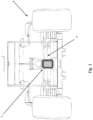
- the reference number 1 schematically illustrates, as a whole, a rear light device of a racing/competition car.
- the rear lighting device 1 is structured to be mounted on a racing/competition car 2.
- the racing/competition car 2 preferably corresponds to a single-seat, open-wheel vehicle.
- the rear light device 1 is mounted centrally in the rear part P of the car 2.
- the single-seat, open-wheel vehicle is preferably designed to be used to do races on circuits/closed tracks.
- the single-seat, open-wheel vehicle is preferably structured for Gran Prix car racing.
- Gran Prix car racing may comprise, for example: Formula 1, Formula 2, Formula Indy, Formula E Gran Prix, or any other similar Gran Prix racing.
- the rear light device 1 is provided with an LED light device 3 comprising a lighting structure provided with a plurality of light-emitting diodes, i.e., LEDs 3a.
- the rear light device 1 is also provided with a mini-LED display 4.
- the mini-LED display 4 comprising a mini-LED electronic matrix 5.
- the mini-LED electronic matrix 5 comprises a plurality of mini-LEDs 7.
- the mini-LED electronic matrix 5 has a face 6 on which there are mini-LEDs placed side by side.
- the mini-LEDs 7 of the mini-LED electronic matrix 5 are arranged on the face 6 so as to form a light-emitting surface.
- the light-emitting surface of the mini-LED display 4 formed by (consisting of) mini-LEDs 7 is conveniently homogeneous and continuous over the whole area occupied by the mini-LEDs 7.
- the mini-LEDs 7 may preferably have a constant pitch across the whole area and are arranged on the face 6 side by side, preferably according to a matrix configuration formed by rows and columns.
- the mini-LED electronic matrix 5 is arranged in a position immediately adjacent to the LEDs 3a of the LED light device 3.
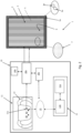
- the rear light device 1 comprises, in addition, an electronic control system 10 configured to selectively drive the LED light device 3 and the mini-LED display 4.
- the electronic control system 10 is configured to control the LEDs 3a of the LED light device 3 in order to perform a photometric lighting function in which it emits/generates a signal light.
- the signal light associated with the photometric lighting function is conveniently designed to signal the presence of the racing car 2 to the drivers of other racing cars, generally the drivers of the racing cars positioned behind the racing car 2.
- the signal light is designed to signal the presence of the car 2 and is, preferably, generated via the LED light device 3 when there is reduced visibility, such as, for example, if there is rain or fog, or similar conditions.
- the electronic control system 10 is also configured in order to control the LEDs 3a of the LED light device 3 to generate the signal light with a first, predetermined light intensity.
- the first, predetermined light intensity may be, for example, greater or equal to approximately 800 cd (candelas).
- the electronic control system 10 is also preferably configured to control the LEDs 3a of the LED light device 3 intermittently.
- the electronic control system 10 is also preferably configured to vary the intermittent frequency of the LEDs 3a of the LED light device 3.
- the electronic control system 10 is also preferably configured in order to vary the intermittent frequency of the LEDs 3a of the LED light device 3 based on the condition to be signalled.
- the electronic control system 10 is also preferably configured to control LEDs 3a according to an intermittent mode when energy harvesting is carried out, to communicate to the cars that follow the car 2 a warning that the car is slowing down.
- the electronic control system 10 may control switching on the LEDs 3a intermittently with a frequency, conveniently, of approximately 2 Hz.
- the electronic control system 10 is also preferably configured to control LEDs 3a according to an intermittent mode when it is raining or there is reduced/limited visibility. For example, when it is raining or visibility is limited, the electronic control system 10 may control switching on the LEDs 3a intermittently with a frequency, conveniently, of approximately 4 Hz.
- the electronic control system 10 is also preferably configured to control LEDs 3a according to an intermittent mode when a safety car or virtual safety car enters or is present on the track. For example, when a safety car or virtual safety car enters or is present on the track, the electronic control system 10 may control switching on the LEDs 3a intermittently with a frequency of 2 Hz for a predetermined interval, for example 10 seconds.
- the electronic control system 10 is also configured so as to control LEDs 3a according to an intermittent mode when there is a pit lane. For example, when there is a pit lane, the electronic control system 10 may control switching on the LEDs 3a intermittently with a frequency of 2 Hz.
- the electronic control system 10 is also configured so as to selectively control the mini-LEDs 7 of the mini-LED electronic matrix 5 of the mini-LED display 4.
- the electronic control system 10 is configured in order to selectively control the mini-LEDs 7 of the mini-LED electronic matrix 5 to perform one or more communication lighting functions.
- the communication lighting functions performed by the mini-LED display 4 are preferably different to the photometric function performed by the LED light device 3.
- the communication lighting functions performed by the mini-LED display 4 preferably provide lighting information via the representation of images/light signs of various kinds, i.e., in graphic, numeric, or alphabetic form.
- the images associated with the communication lighting functions generated by the mini-LED display 4 may comprise, for example, pictograms and/or symbols and/or messages.
- the images associated with the communication lighting functions generated by the mini-LED display 4 of the rear light device 1 may be static (fixed) and/or dynamic (animated images and/or moving images) generated by the mini-LED display 4 of the device.
- the images associated with the communication lighting functions generated by the mini-LED display 4 may, conveniently, be observed/displayed on the outside of the car 2, for example by the drivers of the other cars that are facing the tail end of the car 2.
- the electronic control system 10 is configured so as to selectively control the mini-LEDs 7 of the mini-LED electronic matrix 5 of the mini-LED display 4 during the generation of the images so that the overall intensity of the light is less than a second, predetermined light intensity.
- the second, predetermined light intensity is preferably less than the first, predetermined light intensity.
- the second, predetermined light intensity may be, for example, less than or equal to approximately 150 cd (candelas).
- the electronic control system 10 may comprise a processing and control unit 10a and a memory unit 10b.
- the processing and control unit 10a may comprise, for example, a micro-processor or similar electronic devices.
- the processing and control unit 10a may be configured in order to receive in input a control signals and selectively controls the LED light device 3 and the mini-LED display 4 based on the received control signals.
- the control signals may be indicative of a control to perform a photometric lighting function or a control for performing a communication lighting function.
- the memory unit 10b may store multiple predetermined images associated with corresponding communication lighting functions.
- the processing and control unit 10a may be configured so as to: receive in input a control signal indicative of a communication lighting function, search, in the memory unit 10b, an image among the predetermined images stored corresponding to the communication lighting function, based on said control signal, selectively control the mini-LEDs 7 of the mini-LED electronic matrix 5 of the mini-LED display 4 to display the image found in the memory unit 10b.
- the electronic control system 10 may also comprise at least one electronic user control device 11, which is configured so as to enable the user to impart controls relating to the photometric and/or communication lighting function to be carried out to the rear light device 1, and provides, based on the user-controls imparted, control signals to the processing and control unit 10a.
- the electronic user control device 11 may comprise control devices 11a.
- the control devices 11a may be arranged inside the passenger compartment of the car 2.
- the control devices 11a of the electronic user control device 11 may be comprised (integrated), for example, in the steering wheel 14 of the car 2.
- the control devices 11a may comprise selectors and/or a control panel.
- the control devices 11a may be electrically connected to the processing and control unit 10a and/or may communicate with the latter via a wireless communication system 15 operating in radio frequency (wireless system) so as to provide it with control signals by means of a communication unit 10c included in the electronic control system 10.
- a wireless communication system 15 operating in radio frequency (wireless system) so as to provide it with control signals by means of a communication unit 10c included in the electronic control system 10.
- an electronic user control device 11 may be outside the passenger compartment of the car 2.
- the electronic user control device 11 may comprise, alternatively and/or in addition, a remote computing unit 11b external to the car 2.
- the computing unit 11b of the electronic user control device 11 may comprise a personal computer, laptop, notebook (or any other similar computing electronic device), which, based on controls imparted by the user is designed to communicate control signals to the processing and control unit 10a through, for example, the communication system 15 by means of a communication module 11b.
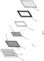
- the rear light device 1 may comprise: a housing body 16, a lenticular body 18, which is firmly coupled to the housing 16, and a printed circuit board 19, which is arranged inside the housing 16.
- the housing body 16 is shaped so as to form a rectangular body, for example a rear one.
- the housing 16 may preferably, but not necessarily, be cup-shaped.
- the housing 16 may comprise a cavity or internal seat 16a.
- the internal seat 16a may have an opening or mouth.
- the lenticular body 18 may be arranged in the rear light device 1 in a front position.
- the lenticular body 18 may define the external face of the rear light device 1.
- the face of the lenticular body 18 is positioned/turned towards the space outside the rear light device 1 and has an inner face turned towards the seat 16a.
- the lenticular body 18 may be shaped like a plate-shaped half-bearing.
- the lenticular body 18 may be, at least partially, two-dimensional, for example rectangular and extend/lie across a flat (almost level) surface.
- the lenticular body 18 may be made, for example, completely and/or at least partially of transparent or semi-transparent or translucid material.
- the lenticular body 18 may be made so that the light emitted by its outer face is a red-coloured light.
- the lenticular body 18 may be an external lens.
- the electronic board 19 may be shaped so as to have a basically rectangular shape and is sized so as to be housed in the seat 16a.
- the LEDs 3a are preferably arranged next to each other on the surface 19a of the electronic board 19 facing the inner face of the lenticular body 18 and are positioned along one or more side edges of the electronic board 19.
- the mini-LED electronic matrix 5 is arranged immediately next to the LEDs 3a and has the mini-LEDs 7 adjacent to the inner face of the lenticular body 18.
- the LEDs 3a are preferably arranged next to each other along the outer edge of the electronic board 19 so as to form/generate, when switched on, an illuminating rectangular outer frame.
- the mini-LEDs 7 of the mini-LED electronic matrix 5 are arranged on the electronic board 19 next to each other so as to completely occupy the inner rectangular portion.
- the mini-LED electronic matrix 5 has a rectangular shape corresponding to the inner rectangular portion.
- the mini-LED electronic matrix 5 is arranged on the electronic board 19 so that the mini-LED display faces the lenticular body 18.
- the LEDs 3a are preferably arranged on the electronic board 19 so as to externally surround the mini-LED electronic matrix 5.
- this invention is not limited to a configuration that involves an arrangement of the LEDs 3a along the outer edge of the electronic board 19 so as to form an illuminating rectangular outer frame, and the positioning of the mini-LED electronic matrix 5 in the inner rectangular portion surrounded by the illuminating rectangular outer frame, but may involve other solutions according to the claims.
- the LEDs 3a may be arranged next to each other so as to form at least one individual vertical and/or horizontal straight luminous segment that extends, for example, along a side edge of the electronic board 19, while the mini-LED electronic matrix 5 may be arranged adjacent to and next to the individual straight luminous segment.
- the rear light device 1 may comprise, in addition, optical collimators 20.
- the optical collimators 20 are placed between the LEDs 3a and the lenticular body 18, and are structured so as to collimate the light emitted by each LED 3a towards a related outer edge of the lenticular body 18.
- the optical collimators 20 are formed by a rectangular optical frame that is inserted outside the frame 22 arranged between the LEDs 3a and the inner face of the lenticular body 18.
- the rear light device 1 may comprise, in addition, optical collimators 21, which are placed between the mini-LEDs 3a and the lenticular body 18 and are structured so as to collimate the light emitted by each mini-LED 7 towards the lenticular body 18.
- the optical collimators 21 may comprise a rectangular plate-shaped element placed between the mini-LED electronic matrix 5 and the inner face of the lenticular body 18.
- optical collimators 21 has the technical effect of increasing the optical performance of the mini-LED electronic matrix 5 in order to provide a significant contribution to the photometry of the signalling function (for example fog-lights or rain-lights).
- the Applicant has found that this use conveniently makes it possible to reduce the optical and electrical power required by the LED light device 3 and, at the same time, increases the visibility of the images (pictograms) including in conditions of low environmental visibility, or in adverse environmental conditions.
- optical collimators 21 has the technical effect of increasing the optical performance of the mini-LED display within a defined portion of the visual field.
- the electronic control circuit 10 is configured so as to: receive from the electronic user control device 11 a control signal indicating a user control associated with the photometric lighting function and, based on the control signal received, it switches on the LEDs 3a.
- the LEDs 3a that are switched on form the luminous rectangular frame.
- the luminous rectangular frame of the rear light device 1 may, preferably, have an outer width L1 of approximately 90 mm, an inner width L2 of approximately 80 mm, an outer height H1 of approximately 118 mm, and an inner height H2 of approximately 108 mm.
- the electronic control circuit 10 may be configured so as to keep the LEDs 3a switched on continuously, when the light signal relating to the photometric lighting function is activated based on the control.
- the user control for activating the photometric lighting function may be imparted by the user, for example, when there is reduced visibility, for example when there is fog or rain, or in other, similar environmental conditions in which the drivers' ability to see the track is reduced.
- the electronic control circuit 10 may also be configured so as to switch on the LEDs 3a discontinuously, or intermittently.
- the electronic control circuit 10 is configured so as to receive from the electronic user control device 11 a control signal indicating a user control associated with the communication lighting function and, based on the control signal received, it controls the mini-LEDs 7 to generate an image via the mini-LED device 4.
- the electronic control circuit 10 may also preferably be configured so as to search in the memory unit 10b, an image among the images stored based on the control signal, and it controls the mini-LEDs 7 to generate, via the mini-LED device 41, the image found and taken from the memory unit.
- the electronic control circuit 10 may also be configured so as to control the mini-LEDs 7 of the mini-LED display 4 so as to display an image that communicates a race condition.
- An image displayed via the mini-LED electronic matrix 5 to represent the condition of the race may contain, for example, an end-of-race message and/or symbol, for example depicting the chequered flag ( Figure 12 ).
- the electronic control circuit 10 may also be configured so as to control the mini-LEDs 7 of the mini-LED electronic matrix 5 so as to display, via the mini-LED device 4, an image that communicates a dangerous conditions.
- the image of the dangerous conditions may contain, for example, a warning message, or a symbol depicting, for example, a warning signal.
- a pictogram of the image could communicate a warning message indicating the intention of the driver of the car 2 to externally signal the near execution of a manoeuvre to enter the pit lane towards the boxes or, vice versa, an exit manoeuvre, or a partial interruption of the race, for example during a pit stop and/or in the event of the slowing down or grouping of vehicles via the safety car or pace car.
- the electronic control circuit 10 may also be configured in order to control the mini-LEDs 7 of the mini-LED electronic matrix 5 so as to display, via the mini-LED device 4, an image that communicates a vehicle condition.
- the image of the vehicle condition may contain, for example, a message relating a characteristic of the vehicle, for example its number, and/or the brand/logo, or the like ( Figures 13 and 14 ).
- the operation method of the rear light device described above essentially involves controlling, via the electronic control system 10, the LEDs 3a of the LED light device so as to perform a photometric lighting function in which it emits a signal light to signal the presence of the racing car 2 to the drivers of other racing cars, and/or to control, via the electronic control system 10, the mini-LEDs 7 of the mini-LED display 4 to perform a communication lighting function in which it displays an image.
- the method comprises the step of storing a plurality of images in the memory unit 10b of the electronic control system 10, receiving, via the electronic control system 10, a control signal indicating at least one image to be displayed via the rear light device 1, finding, in the memory unit 10b, an image among the images stored, based on said control signal, controlling, via the electronic control system 10, the mini-LEDs 7 of the mini-LED display 4, so as to display the image selected.
- the rear light device advantageously enables performing, in addition to the photometric lighting function, for example, an anti-fog and/or anti-rain lighting function, including communication lighting functions towards the outside and, in particular, directed to the other drivers, increasing, thus, the exchange of information and/or signals among the same, and increasing safety.
- the photometric lighting function for example, an anti-fog and/or anti-rain lighting function, including communication lighting functions towards the outside and, in particular, directed to the other drivers, increasing, thus, the exchange of information and/or signals among the same, and increasing safety.
- this invention is advantageous since the lighting device, thanks to the architecture described above, is able to carry out, in addition to the conventional lighting signals obtained via the LEDs, the display of images as well, something that cannot be implemented using known devices.
- this invention is not limited to a rear light device 1 provided with a mini-LED display 4.
- the rear light device differs from that described above due to the fact that the mini-LED display 4 is replaced by a micro-LED display.
- the micro-LED display comprises a micro-LED matrix provided, in turn, with multiple micro-LEDs. The micro-LEDs are, thus, arranged on the electronic board 19 and are activated to perform the communication lighting functions.
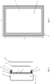
- FIG 8 relates to a rear light device 100, which is similar to the rear light device 1 shown in Figures 6 and 7 , and whose component parts will be identified, where possible, with the same reference numbers that identify corresponding parts of the rear light device 1.
- the rear light device 100 shown in Figure 8 differs from the rear light device 1 shown in Figures 6 and 7 due to the fact that the LEDs 3a are arranged on the surface 19b of the electronic board 19 opposite the surface 19a.
- the rear light device 100 comprises a plurality of LEDs 3a that are arranged on the surface 19b at the rectangular outer edge of the electronic board 19 and a light guide plate 23 arranged with its inner wall facing the LEDs 3a.
- the light guide plate 23 has the shape of a rectangular frame and is structured so as to deviate the light emitted by the LEDs 3a towards the outer edge of the lenticular body 19 so as to create the illuminating rectangular frame.
- the technical effect obtained is that of exploiting both the faces of the electronic board and extending the optical path of the light emitted by the LEDs 3a so as to obtain greater homogeneity of the light generated during the execution of the photometric signalling function.
Landscapes
- Engineering & Computer Science (AREA)
- Mechanical Engineering (AREA)
- General Engineering & Computer Science (AREA)
- Physics & Mathematics (AREA)
- Microelectronics & Electronic Packaging (AREA)
- Optics & Photonics (AREA)
- Illuminated Signs And Luminous Advertising (AREA)
Claims (11)
- Rücklichtvorrichtung (1) (100) für einen Rennwagen (2), umfassend:eine LED-Lichtvorrichtung (3), umfassend eine LED-Beleuchtungsstruktur, die mit mehreren LEDs (3a) versehen ist, undeine Anzeigevorrichtung (4), die aus einer elektronischen Mini-LED-Matrix (5) oder einer elektronischen Mikro-LED-Matrix besteht und in einer Position angrenzend an die LEDs (3a) der LED-Leuchtvorrichtung (3) angeordnet ist,ein elektronisches Steuersystem (10), das konfiguriert ist, um selektiv zu steuern:
die LED-Lichtvorrichtung (3), um durch die LEDs (3a) ein Signallicht auszusenden, um den Fahrern anderer Rennwagen die Anwesenheit des Wagens (2) zu signalisieren, und/oder- die Anzeigevorrichtung (4), um mindestens ein Bild anzuzeigen, die Rücklichtvorrichtung umfassend:einen Gehäusekörper (16)einen linsenförmigen Körper (18), der mit dem Gehäusekörper (16) gekoppelt isteine elektronische Platine (19), die im Inneren des Gehäusekörpers (16) angeordnet ist,wobei die elektronische Mini-LED-Matrix (5) oder die elektronische Mikro-LED-Matrix auf der elektronischen Platine (19) dem linsenförmigen Körper (18) zugewandt angeordnet istwobei die LEDs (3a) der LED-Beleuchtungsstruktur auf der elektronischen Platine (19) angeordnet sind, um die elektronische Mini-LED-Matrix oder die elektronische Mikro-LED-Matrix äußerlich zu umgeben,dadurch gekennzeichnet, dass die LEDs (3a) der LED-Beleuchtungsstruktur auf einer zweiten Oberfläche der elektronischen Platine (19) gegenüber dem linsenförmigen Körper (18) angeordnet und mit Lichtleiterplatten (23) optisch gekoppelt sind, die strukturiert sind, um das Licht der LEDs (3a) in Richtung des linsenförmigen Körpers (18) zu leiten. - Rücklichtvorrichtung nach Anspruch 1, wobei das elektronische Steuersystem (10) Speichermittel (10b) umfasst, die ausgelegt sind, um eine Vielzahl von Bildern zu speichern, wobei das elektronische Steuersystem (10) konfiguriert ist zum:Empfangen an einem Eingang eines Steuersignals, das mit mindestens einem Bild verknüpft ist, das über die Rücklichtvorrichtung anzuzeigen ist,Suchen eines Bilds unter den gespeicherten Bildern in dem Speichermittel (10b) basierend auf dem Steuersignal,Steuern der Anzeigevorrichtung (4), um das Bild anzuzeigen.
- Rücklichtvorrichtung nach Anspruch 1 oder 2, wobei das elektronische Steuersystem (10) ebenso konfiguriert ist, um die Mini-LEDs (7) und/oder die Mikro-LEDs der elektronischen Matrix der Anzeigevorrichtung (4) zu steuern, um ein Bild zu erzeugen, das mindestens eines enthält von: einer Nachricht und/oder einem Symbol und/oder einem Piktogramm.
- Rücklichtvorrichtung nach einem der vorstehenden Ansprüche, wobei das elektronische Steuersystem (10) ebenso konfiguriert ist, um die Mini-LEDs (7) und/oder die Mikro-LEDs der elektronischen Matrix der Anzeigevorrichtung (4) zu steuern, um ein Bild anzuzeigen, das einen Rennzustand angibt.
- Rücklichtvorrichtung nach einem der vorstehenden Ansprüche, wobei das elektronische Steuersystem ebenso konfiguriert ist, um die Mini-LEDs und/oder die Mikro-LEDs der elektronischen Matrix der Anzeigevorrichtung (4) zu steuern, um ein Bild anzuzeigen, das einen gefährlichen Zustand angibt.
- Rücklichtvorrichtung nach einem der vorstehenden Ansprüche, wobei das elektronische Steuersystem ebenso konfiguriert ist, um die Mini-LEDs (7) und/oder die Mikro-LEDs der elektronischen Matrix der Anzeigevorrichtung (4) zu steuern, um ein drittes Bild anzuzeigen, das einen Rennzustand des Rennwagens (2) während des Rennens angibt.
- Rücklichtvorrichtung nach einem der vorstehenden Ansprüche, wobei die elektronische Mini-LED-Matrix (5) und/oder die elektronische Mikro-LED-Matrix der Mini-LED-Anzeige (4) eine flache rechteckige Form aufweist.
- Rücklichtvorrichtung nach einem der vorstehenden Ansprüche, wobei die LEDs (3a) der LED-Lichtvorrichtung (3) nebeneinander auf einer Ebene angeordnet sind, um einen rechteckigen LED-Rahmen auszubilden.
- Rücklichtvorrichtung nach Anspruch 8, wobei der rechteckige LED-Rahmen die elektronische Mini-LED-Matrix oder die elektronische Mikro-LED-Matrix umgibt.
- Rücklichtvorrichtung nach Anspruch 9, wobei das elektronische Steuersystem (10) konfiguriert ist zum:Empfangen an dem Eingang eines Steuersignals, das einen Nebelzustand oder einen Regenzustand angibt,Steuern der LED-Lichtvorrichtung (3), um entlang des Außenrahmens ein homogenes Signallicht zu erzeugen, das eine erste Lichtintensität aufweist,Steuern der Anzeigevorrichtung (4), um in dem Bereich, der durch den Außenrahmen begrenzt ist, ein Bild zu erzeugen, das eine zweite Lichtintensität aufweist, die geringer als die erste Lichtintensität ist.
- Rennwagen, der mit einer Rücklichtvorrichtung nach einem der Ansprüche 1 bis 10 versehen ist.
Priority Applications (1)
| Application Number | Priority Date | Filing Date | Title |
|---|---|---|---|
| EP22209027.6A EP4375140B1 (de) | 2022-11-23 | 2022-11-23 | Rücklichtvorrichtung eines rennfahrzeugs und zugehöriges rennfahrzeug |
Applications Claiming Priority (1)
| Application Number | Priority Date | Filing Date | Title |
|---|---|---|---|
| EP22209027.6A EP4375140B1 (de) | 2022-11-23 | 2022-11-23 | Rücklichtvorrichtung eines rennfahrzeugs und zugehöriges rennfahrzeug |
Publications (2)
| Publication Number | Publication Date |
|---|---|
| EP4375140A1 EP4375140A1 (de) | 2024-05-29 |
| EP4375140B1 true EP4375140B1 (de) | 2025-05-28 |
Family
ID=84829913
Family Applications (1)
| Application Number | Title | Priority Date | Filing Date |
|---|---|---|---|
| EP22209027.6A Active EP4375140B1 (de) | 2022-11-23 | 2022-11-23 | Rücklichtvorrichtung eines rennfahrzeugs und zugehöriges rennfahrzeug |
Country Status (1)
| Country | Link |
|---|---|
| EP (1) | EP4375140B1 (de) |
Family Cites Families (9)
| Publication number | Priority date | Publication date | Assignee | Title |
|---|---|---|---|---|
| DE102011076330A1 (de) * | 2011-05-24 | 2012-11-29 | Osram Ag | FAHRZEUGAUßENBELEUCHTUNG MIT SIGNALISIERUNGSFUNKTION |
| KR101262546B1 (ko) * | 2011-11-09 | 2013-05-08 | 기아자동차주식회사 | 차량용 램프구조 |
| KR20140079932A (ko) * | 2012-12-20 | 2014-06-30 | 에스엘 주식회사 | 차량용 램프 |
| GB201416016D0 (en) * | 2014-09-10 | 2014-10-22 | Hamilton Anthony C | Infomation Display Module |
| FR3026689A1 (fr) * | 2014-10-02 | 2016-04-08 | Valeo Vision | Dispositif de signalisation a affichage de pictogrammes pour vehicule automobile, et feu de signalisation muni d'un tel dispositif lumineux |
| EP3351850B1 (de) * | 2015-09-17 | 2020-09-09 | Furukawa Electric Co., Ltd. | Led-beleuchtungsvorrichtung und verfahren zum extrahieren von licht einer led-beleuchtungsvorrichtung |
| JP2019001398A (ja) * | 2017-06-19 | 2019-01-10 | 株式会社小糸製作所 | 車両用灯具 |
| JP2019034640A (ja) * | 2017-08-14 | 2019-03-07 | 株式会社小糸製作所 | 車両用灯具 |
| DE102019215332A1 (de) * | 2019-10-07 | 2021-04-08 | W. Gessmann Gmbh | Lichtsignalvorrichtung für ein fahrerloses Transportsystem |
-
2022
- 2022-11-23 EP EP22209027.6A patent/EP4375140B1/de active Active
Also Published As
| Publication number | Publication date |
|---|---|
| EP4375140A1 (de) | 2024-05-29 |
Similar Documents
| Publication | Publication Date | Title |
|---|---|---|
| US8325029B2 (en) | Multiple color multi-functional light bar | |
| GB2240650A (en) | Vehicle display device | |
| EP3671018B1 (de) | Fahrzeug-winglet, sequentielle blinkeranordnung und system zur sequentiellen beleuchtung von bereichen eines fahrzeug-winglets | |
| US12429188B2 (en) | Illumination apparatus for a motor vehicle | |
| US11137598B2 (en) | Display device | |
| JP4193367B2 (ja) | 車両用表示装置 | |
| US20140268852A1 (en) | Expressive vehicle lighting assembly | |
| KR101351656B1 (ko) | 차량용 글랜스 라이트 장치 | |
| KR20140079932A (ko) | 차량용 램프 | |
| KR20050056207A (ko) | 회전하는 가시 표면상의 정보 시각화 장치 | |
| EP3355096A1 (de) | Anzeigesystem für ein fahrzeug | |
| EP4375140B1 (de) | Rücklichtvorrichtung eines rennfahrzeugs und zugehöriges rennfahrzeug | |
| JP2008116766A (ja) | 表示器および虚像表示装置 | |
| JP5672482B2 (ja) | 車両用表示装置 | |
| US20070030139A1 (en) | Method and apparatus for reducing road rage | |
| CN113597572A (zh) | 光学装置,布置,车辆和方法 | |
| EP2865556A1 (de) | Anzeigevorrichtung für ein fahrzeug | |
| JP5103838B2 (ja) | 表示装置 | |
| JP2003039983A (ja) | 車両用表示装置 | |
| JP2004226364A (ja) | 車両用表示装置 | |
| JP2013241035A (ja) | 車両用表示装置 | |
| JP7222330B2 (ja) | 表示装置 | |
| JP2010127801A (ja) | 車両用表示装置 | |
| JP2003083775A (ja) | 車両用表示装置 | |
| CN111251983A (zh) | 一种路况提示系统、方法及车辆 |
Legal Events
| Date | Code | Title | Description |
|---|---|---|---|
| PUAI | Public reference made under article 153(3) epc to a published international application that has entered the european phase |
Free format text: ORIGINAL CODE: 0009012 |
|
| STAA | Information on the status of an ep patent application or granted ep patent |
Free format text: STATUS: THE APPLICATION HAS BEEN PUBLISHED |
|
| AK | Designated contracting states |
Kind code of ref document: A1 Designated state(s): AL AT BE BG CH CY CZ DE DK EE ES FI FR GB GR HR HU IE IS IT LI LT LU LV MC ME MK MT NL NO PL PT RO RS SE SI SK SM TR |
|
| STAA | Information on the status of an ep patent application or granted ep patent |
Free format text: STATUS: REQUEST FOR EXAMINATION WAS MADE |
|
| 17P | Request for examination filed |
Effective date: 20241126 |
|
| RBV | Designated contracting states (corrected) |
Designated state(s): AL AT BE BG CH CY CZ DE DK EE ES FI FR GB GR HR HU IE IS IT LI LT LU LV MC ME MK MT NL NO PL PT RO RS SE SI SK SM TR |
|
| GRAP | Despatch of communication of intention to grant a patent |
Free format text: ORIGINAL CODE: EPIDOSNIGR1 |
|
| STAA | Information on the status of an ep patent application or granted ep patent |
Free format text: STATUS: GRANT OF PATENT IS INTENDED |
|
| RIC1 | Information provided on ipc code assigned before grant |
Ipc: F21S 43/14 20180101ALI20250121BHEP Ipc: F21S 43/31 20180101ALI20250121BHEP Ipc: F21S 43/19 20180101ALI20250121BHEP Ipc: F21S 43/15 20180101ALI20250121BHEP Ipc: B60Q 1/00 20060101ALI20250121BHEP Ipc: B60Q 1/26 20060101ALI20250121BHEP Ipc: B60Q 1/30 20060101ALI20250121BHEP Ipc: B60Q 1/50 20060101AFI20250121BHEP |
|
| INTG | Intention to grant announced |
Effective date: 20250213 |
|
| GRAS | Grant fee paid |
Free format text: ORIGINAL CODE: EPIDOSNIGR3 |
|
| GRAA | (expected) grant |
Free format text: ORIGINAL CODE: 0009210 |
|
| STAA | Information on the status of an ep patent application or granted ep patent |
Free format text: STATUS: THE PATENT HAS BEEN GRANTED |
|
| P01 | Opt-out of the competence of the unified patent court (upc) registered |
Free format text: CASE NUMBER: APP_15131/2025 Effective date: 20250327 |
|
| AK | Designated contracting states |
Kind code of ref document: B1 Designated state(s): AL AT BE BG CH CY CZ DE DK EE ES FI FR GB GR HR HU IE IS IT LI LT LU LV MC ME MK MT NL NO PL PT RO RS SE SI SK SM TR |
|
| REG | Reference to a national code |
Ref country code: GB Ref legal event code: FG4D |
|
| REG | Reference to a national code |
Ref country code: CH Ref legal event code: EP |
|
| REG | Reference to a national code |
Ref country code: IE Ref legal event code: FG4D Ref country code: DE Ref legal event code: R096 Ref document number: 602022015178 Country of ref document: DE |
|
| REG | Reference to a national code |
Ref country code: NL Ref legal event code: MP Effective date: 20250528 |
|
| PG25 | Lapsed in a contracting state [announced via postgrant information from national office to epo] |
Ref country code: FI Free format text: LAPSE BECAUSE OF FAILURE TO SUBMIT A TRANSLATION OF THE DESCRIPTION OR TO PAY THE FEE WITHIN THE PRESCRIBED TIME-LIMIT Effective date: 20250528 Ref country code: ES Free format text: LAPSE BECAUSE OF FAILURE TO SUBMIT A TRANSLATION OF THE DESCRIPTION OR TO PAY THE FEE WITHIN THE PRESCRIBED TIME-LIMIT Effective date: 20250528 |
|
| REG | Reference to a national code |
Ref country code: LT Ref legal event code: MG9D |
|
| PG25 | Lapsed in a contracting state [announced via postgrant information from national office to epo] |
Ref country code: NO Free format text: LAPSE BECAUSE OF FAILURE TO SUBMIT A TRANSLATION OF THE DESCRIPTION OR TO PAY THE FEE WITHIN THE PRESCRIBED TIME-LIMIT Effective date: 20250828 Ref country code: GR Free format text: LAPSE BECAUSE OF FAILURE TO SUBMIT A TRANSLATION OF THE DESCRIPTION OR TO PAY THE FEE WITHIN THE PRESCRIBED TIME-LIMIT Effective date: 20250829 |
|
| PG25 | Lapsed in a contracting state [announced via postgrant information from national office to epo] |
Ref country code: NL Free format text: LAPSE BECAUSE OF FAILURE TO SUBMIT A TRANSLATION OF THE DESCRIPTION OR TO PAY THE FEE WITHIN THE PRESCRIBED TIME-LIMIT Effective date: 20250528 Ref country code: PL Free format text: LAPSE BECAUSE OF FAILURE TO SUBMIT A TRANSLATION OF THE DESCRIPTION OR TO PAY THE FEE WITHIN THE PRESCRIBED TIME-LIMIT Effective date: 20250528 |
|
| PG25 | Lapsed in a contracting state [announced via postgrant information from national office to epo] |
Ref country code: BG Free format text: LAPSE BECAUSE OF FAILURE TO SUBMIT A TRANSLATION OF THE DESCRIPTION OR TO PAY THE FEE WITHIN THE PRESCRIBED TIME-LIMIT Effective date: 20250528 |
|
| PG25 | Lapsed in a contracting state [announced via postgrant information from national office to epo] |
Ref country code: HR Free format text: LAPSE BECAUSE OF FAILURE TO SUBMIT A TRANSLATION OF THE DESCRIPTION OR TO PAY THE FEE WITHIN THE PRESCRIBED TIME-LIMIT Effective date: 20250528 |
|
| PG25 | Lapsed in a contracting state [announced via postgrant information from national office to epo] |
Ref country code: RS Free format text: LAPSE BECAUSE OF FAILURE TO SUBMIT A TRANSLATION OF THE DESCRIPTION OR TO PAY THE FEE WITHIN THE PRESCRIBED TIME-LIMIT Effective date: 20250828 |
|
| PG25 | Lapsed in a contracting state [announced via postgrant information from national office to epo] |
Ref country code: IS Free format text: LAPSE BECAUSE OF FAILURE TO SUBMIT A TRANSLATION OF THE DESCRIPTION OR TO PAY THE FEE WITHIN THE PRESCRIBED TIME-LIMIT Effective date: 20250928 |
|
| PG25 | Lapsed in a contracting state [announced via postgrant information from national office to epo] |
Ref country code: LV Free format text: LAPSE BECAUSE OF FAILURE TO SUBMIT A TRANSLATION OF THE DESCRIPTION OR TO PAY THE FEE WITHIN THE PRESCRIBED TIME-LIMIT Effective date: 20250528 |
|
| REG | Reference to a national code |
Ref country code: AT Ref legal event code: MK05 Ref document number: 1798463 Country of ref document: AT Kind code of ref document: T Effective date: 20250528 |
|
| PGFP | Annual fee paid to national office [announced via postgrant information from national office to epo] |
Ref country code: DE Payment date: 20251022 Year of fee payment: 4 |
|
| PG25 | Lapsed in a contracting state [announced via postgrant information from national office to epo] |
Ref country code: DK Free format text: LAPSE BECAUSE OF FAILURE TO SUBMIT A TRANSLATION OF THE DESCRIPTION OR TO PAY THE FEE WITHIN THE PRESCRIBED TIME-LIMIT Effective date: 20250528 Ref country code: SM Free format text: LAPSE BECAUSE OF FAILURE TO SUBMIT A TRANSLATION OF THE DESCRIPTION OR TO PAY THE FEE WITHIN THE PRESCRIBED TIME-LIMIT Effective date: 20250528 Ref country code: AT Free format text: LAPSE BECAUSE OF FAILURE TO SUBMIT A TRANSLATION OF THE DESCRIPTION OR TO PAY THE FEE WITHIN THE PRESCRIBED TIME-LIMIT Effective date: 20250528 |
|
| PGFP | Annual fee paid to national office [announced via postgrant information from national office to epo] |
Ref country code: IT Payment date: 20251201 Year of fee payment: 4 |
|
| PGFP | Annual fee paid to national office [announced via postgrant information from national office to epo] |
Ref country code: FR Payment date: 20251022 Year of fee payment: 4 |
|
| PG25 | Lapsed in a contracting state [announced via postgrant information from national office to epo] |
Ref country code: CZ Free format text: LAPSE BECAUSE OF FAILURE TO SUBMIT A TRANSLATION OF THE DESCRIPTION OR TO PAY THE FEE WITHIN THE PRESCRIBED TIME-LIMIT Effective date: 20250528 |
|
| PG25 | Lapsed in a contracting state [announced via postgrant information from national office to epo] |
Ref country code: EE Free format text: LAPSE BECAUSE OF FAILURE TO SUBMIT A TRANSLATION OF THE DESCRIPTION OR TO PAY THE FEE WITHIN THE PRESCRIBED TIME-LIMIT Effective date: 20250528 |
|
| PG25 | Lapsed in a contracting state [announced via postgrant information from national office to epo] |
Ref country code: SK Free format text: LAPSE BECAUSE OF FAILURE TO SUBMIT A TRANSLATION OF THE DESCRIPTION OR TO PAY THE FEE WITHIN THE PRESCRIBED TIME-LIMIT Effective date: 20250528 |
|
| PG25 | Lapsed in a contracting state [announced via postgrant information from national office to epo] |
Ref country code: RO Free format text: LAPSE BECAUSE OF FAILURE TO SUBMIT A TRANSLATION OF THE DESCRIPTION OR TO PAY THE FEE WITHIN THE PRESCRIBED TIME-LIMIT Effective date: 20250528 |