EP4373382B1 - Endoskop mit drehantrieb - Google Patents
Endoskop mit drehantrieb Download PDFInfo
- Publication number
- EP4373382B1 EP4373382B1 EP23789571.9A EP23789571A EP4373382B1 EP 4373382 B1 EP4373382 B1 EP 4373382B1 EP 23789571 A EP23789571 A EP 23789571A EP 4373382 B1 EP4373382 B1 EP 4373382B1
- Authority
- EP
- European Patent Office
- Prior art keywords
- endoscope
- shaft
- sleeve
- cable
- distal
- Prior art date
- Legal status (The legal status is an assumption and is not a legal conclusion. Google has not performed a legal analysis and makes no representation as to the accuracy of the status listed.)
- Active
Links
Images
Classifications
-
- A—HUMAN NECESSITIES
- A61—MEDICAL OR VETERINARY SCIENCE; HYGIENE
- A61B—DIAGNOSIS; SURGERY; IDENTIFICATION
- A61B1/00—Instruments for performing medical examinations of the interior of cavities or tubes of the body by visual or photographical inspection, e.g. endoscopes; Illuminating arrangements therefor
- A61B1/005—Flexible endoscopes
- A61B1/0051—Flexible endoscopes with controlled bending of insertion part
- A61B1/0057—Constructional details of force transmission elements, e.g. control wires
-
- A—HUMAN NECESSITIES
- A61—MEDICAL OR VETERINARY SCIENCE; HYGIENE
- A61B—DIAGNOSIS; SURGERY; IDENTIFICATION
- A61B1/00—Instruments for performing medical examinations of the interior of cavities or tubes of the body by visual or photographical inspection, e.g. endoscopes; Illuminating arrangements therefor
- A61B1/005—Flexible endoscopes
- A61B1/0051—Flexible endoscopes with controlled bending of insertion part
- A61B1/0055—Constructional details of insertion parts, e.g. vertebral elements
-
- A—HUMAN NECESSITIES
- A61—MEDICAL OR VETERINARY SCIENCE; HYGIENE
- A61B—DIAGNOSIS; SURGERY; IDENTIFICATION
- A61B1/00—Instruments for performing medical examinations of the interior of cavities or tubes of the body by visual or photographical inspection, e.g. endoscopes; Illuminating arrangements therefor
- A61B1/31—Instruments for performing medical examinations of the interior of cavities or tubes of the body by visual or photographical inspection, e.g. endoscopes; Illuminating arrangements therefor for the rectum, e.g. proctoscopes, sigmoidoscopes, colonoscopes
-
- A—HUMAN NECESSITIES
- A61—MEDICAL OR VETERINARY SCIENCE; HYGIENE
- A61B—DIAGNOSIS; SURGERY; IDENTIFICATION
- A61B1/00—Instruments for performing medical examinations of the interior of cavities or tubes of the body by visual or photographical inspection, e.g. endoscopes; Illuminating arrangements therefor
- A61B1/012—Instruments for performing medical examinations of the interior of cavities or tubes of the body by visual or photographical inspection, e.g. endoscopes; Illuminating arrangements therefor characterised by internal passages or accessories therefor
- A61B1/018—Instruments for performing medical examinations of the interior of cavities or tubes of the body by visual or photographical inspection, e.g. endoscopes; Illuminating arrangements therefor characterised by internal passages or accessories therefor for receiving instruments
-
- A—HUMAN NECESSITIES
- A61—MEDICAL OR VETERINARY SCIENCE; HYGIENE
- A61B—DIAGNOSIS; SURGERY; IDENTIFICATION
- A61B1/00—Instruments for performing medical examinations of the interior of cavities or tubes of the body by visual or photographical inspection, e.g. endoscopes; Illuminating arrangements therefor
- A61B1/04—Instruments for performing medical examinations of the interior of cavities or tubes of the body by visual or photographical inspection, e.g. endoscopes; Illuminating arrangements therefor combined with photographic or television appliances
- A61B1/05—Instruments for performing medical examinations of the interior of cavities or tubes of the body by visual or photographical inspection, e.g. endoscopes; Illuminating arrangements therefor combined with photographic or television appliances characterised by the image sensor, e.g. camera, being in the distal end portion
Definitions
- the present disclosure relates to an endoscope having a substantially tubular proximal shaft which is designed for insertion into a patient's body and extends along a shaft axis, a substantially tubular steering section which is arranged distally from the shaft and can be bent with respect to the shaft axis, an endoscope head which is arranged distally from the steering section and has an optic and a working channel outlet, and a rotation mechanism which is configured to rotate the steering section with respect to the shaft about the shaft axis.
- Endoscopes are medical tools for the visual exploration of cavities in a patient's body. They generally have optical devices on the distal endoscope head, i.e. the endoscope head facing away from the user or the patient's body, a proximal endoscope operating section or endoscope handle, i.e. the endoscope head facing the user, and a flexible or rigid (rigid) shaft that connects the endoscope head and the proximal endoscope operating section or endoscope handle.
- the endoscope usually also has a working channel that extends from the proximal endoscope operating section through the shaft to a working channel outlet formed on the endoscope head and enables the extracorporeal insertion and use of a medical instrument such as forceps, scissors, needle, loop, knife and the like.
- Many endoscopes also have deflections, i.e. a controllable shaft section which is arranged between the shaft and the endoscope head to enable the endoscope to be controlled in a patient cavity.
- Such endoscopes can optionally be provided with additional capabilities, for example by placing a cap or sleeve on the endoscope head on the radial outside of the distal endoscope end/endoscope head, which is provided or equipped with certain functions/functional elements, whereby the endoscope not only for exploration and/or as access for therapeutic applications but also as a minimally invasive instrument for carrying out a surgical procedure.
- a cap or sleeve on the endoscope head on the radial outside of the distal endoscope end/endoscope head, which is provided or equipped with certain functions/functional elements, whereby the endoscope not only for exploration and/or as access for therapeutic applications but also as a minimally invasive instrument for carrying out a surgical procedure.
- various diagnostic and/or therapeutic procedures require imaging and/or, if necessary, therapeutic techniques on the patient's bile and/or pancreatic ducts and hepatic ducts.
- Vater's papilla which forms the common exit of the bile and pancreatic ducts into the duodenum, protrudes laterally into the duodenum
- conventional prograde (looking in the longitudinal direction of the endoscope) endoscopes are unsuitable for approaching and inserting surgical instruments into the bile duct, as there is not enough space in the narrow duodenum (diameter 3 to 4 cm) to align their prograde optics and the working channel in a sideways-looking position, as a typical bending radius of such devices is around 6 cm.
- this bending radius or this pivoting is often achieved by so-called “deflectings”, i.e. actively bendable shaft sections arranged between the shaft and the endoscope head, in particular immediately in front of the endoscope head in the proximal direction.
- deflectings i.e. actively bendable shaft sections arranged between the shaft and the endoscope head, in particular immediately in front of the endoscope head in the proximal direction.
- duodenoscopes are specially manufactured for this purpose, which have a lateral (sideways looking) or retrograde (backward looking) optic (also called “side optic”) and a sideways directed or opening working channel.
- a so-called Albarran lever can be provided at a prograde (axially opening) outlet of the working channel of such duodenoscopes, which enables a targeted guidance/redirection of an instrument guided in the working channel by manually pivoting. Due to the sideways directed arrangement of the Functional units, particularly optics and lighting on the endoscope head, enable imaging and treatment in the area of the duodenum with optimal use of the available space.
- a folding mechanism for the folding or bendable mounting of an endoscope head is known, with a number of axially successive segments that can be actively adjusted to an angle relative to one another by means of an actuating element, i.e. manually controlled.
- This design makes it possible to pivot the distal endoscope head in a very narrow radius into a radial alignment, such that the distal front side of the endoscope head does not or only slightly protrudes radially beyond the outer circumference of the endoscope shaft.
- the disadvantage of this mechanism is that such a mechanism is only suitable for folding in a single specific direction, and thus the range of applications of the associated endoscope is limited. It can also be problematic if the folding mechanism is incorrectly aligned at the point in the patient cavity to be examined.
- WO 2012/070781 A2 discloses a rotation mechanism that connects a flexible endoscope shaft to a bending mechanism arranged distally thereto so that it can rotate around the shaft axis, with various drives being provided.
- these drives are very complex and require a lot of space and/or are, as in the case of a drive via a cable, prone to errors and fragile.
- Another rotating mechanism that uses a cable pull is from the WO 2021/079 221 A1
- the rope is redirected via eyelets on a rotating sleeve.
- the object underlying the disclosure is to avoid or reduce disadvantages of the prior art.
- an endoscope with a controllable endoscope head and a simple, robust rotary drive is to be provided.
- an endoscope with a substantially tubular shaft, which is designed for insertion into a patient's body and extends along a shaft axis, an endoscope head, which is arranged distally from the shaft, can be bent or folded down with respect to the shaft axis and has a camera and an outlet of a working channel, a rotation mechanism, which is arranged between the endoscope head and the shaft and is configured to rotate the endoscope head with respect to the shaft about the shaft axis.
- the rotation mechanism has a base sleeve, which is pivotable with respect to the Shaft axis is connected to the shaft in a rotationally fixed manner, and a rotary sleeve which is connected to the endoscope head or an intermediate section in a rotationally fixed manner with respect to the shaft axis, the rotary sleeve and the base sleeve being nested inside one another.
- the rotary mechanism also has a first cable with a distal cable section which is attached to the rotary sleeve in such a way that the first cable can be wound up or unwound around the rotary sleeve, the base sleeve forming a first guide section in the form of a grooved or slot-shaped receptacle in its side wall or on/in a surface of the side wall radially opposite (i.e. opposite) the rotary sleeve, in which the first cable is guided.
- the grooved or slot-shaped receptacle is closed at least on one side facing the rotary sleeve, e.g.
- a separate wall section which is however firmly connected to the base sleeve, can be, for example, a wall section, such as a tube, in which the first cable is guided, which is firmly inserted into the grooved or slotted receptacle of the base sleeve (e.g. by soldering, gluing or the like).
- the base sleeve forms a first distal passage through which the first cable is guided from the first guide section to the rotary sleeve.
- the passage connects the grooved or slotted receptacle or, if applicable, an element inserted therein, such as the tube, to a side of the base element facing the rotary sleeve, so that the cable is guided from the grooved or slotted receptacle through the passage to the rotary sleeve.
- the passage can be a hole in the integral or separate wall section, which is however firmly connected to the base sleeve.
- the passage may be through a gap between a distal end of the grooved or slotted receptacle and a distal end of the separate wall section inserted therein (eg a distal end of the tube).
- the first rope may be wound around the rotating sleeve.
- an endoscope which has a shaft and a distal endoscope section with a bendable or foldable endoscope head and a rotary drive between the shaft and the distal endoscope section.
- the rotary drive is a cable drive which is based on based on the fact that a first cable is provided which is wound in the circumferential direction on a rotating sleeve (also referred to as a spool), and by pulling on the first cable, the first cable is unwound and the rotating sleeve is thereby rotated.
- the rotating sleeve is rotatable and preferably axially fixed to a base sleeve which connects the rotating mechanism to the shaft.
- the shaft can be rigid or flexible.
- the endoscope head can also have a lighting device and/or a rinsing device and/or other elements which are connected to associated lines. Nested means that the two sleeves (rotating sleeve and base sleeve) at least partially overlap axially or that one of the two sleeves is inserted into the other of the two sleeves.
- the rotation mechanism is operated by pulling on the first cable, which is wound around the rotating sleeve. This causes the cable to unwind from the rotating sleeve and drive it in the circumferential direction, i.e. rotating it.
- the endoscope head can be folded or bent, in particular with respect to the shaft axis, in particular to exactly one side (i.e. in a single radial direction).
- the rotating mechanism of the above endoscope has a particularly simple configuration and is therefore inexpensive to manufacture. Furthermore, the rotating mechanism is low-friction and therefore easy to operate. In addition, the first rope is guided and redirected particularly securely so that it is guided safely. The risk of the rope breaking is thus minimized.
- a second cable is provided, which is guided in the distal direction through a second guide section in the form of a groove- or slot-shaped receptacle in the base sleeve and is wound or can be wound around the rotary sleeve in a circumferential direction opposite to the first cable.
- the base sleeve forms a second distal passage at the distal end of the second guide section, which is spaced apart from the first passage in the circumferential direction and through which the second cable is guided.
- the second guide section and the second cable run in a mirror image of the first guide section and the first cable.
- the rotating sleeve is rotated in different directions.
- at least one of the two cables is always wound around the rotating sleeve. In a neutral position, both cables are wound around the rotating sleeve by at least 180°.
- the first and/or the second cable is designed and dimensioned such that it is wound or can be wound around the rotating sleeve by at least 360°.
- the rotating sleeve can have one or more fastening holes, in particular radial bores, in which the first and/or the second cable is fastened. This enables the cables to be attached to the rotating sleeve in a simple and secure manner.
- the first and/or the second cable is each guided in a capillary tube, which is attached in or on the first or second guide section of the base sleeve in a substantially fixed position.
- the capillary tube can have a wall thickness of 0.4 mm, for example, and be attached to the first or second guide section, e.g. glued or soldered in.
- the first and/or second guide section is open on a radial outer side of the base sleeve, in particular along its entire length. This makes mounting the first or second cable and, if applicable, the capillary tubes in the respective guide section particularly easy.
- At least one section of the first and/or second guide section runs immediately proximal to the first or second passage at an angle or transversely to the shaft axis.
- a proximal section of the first and/or second guide section runs parallel to one another and to the shaft axis.
- the proximal sections can also be connected to one another and formed by a common groove, channel or slot-shaped receptacle.
- a distal region of the guide sections i.e.
- the guide sections move away from one another in the circumferential direction.
- the second guide section preferably runs at least in the section immediately proximal to the second through-opening obliquely or transversely to the shaft axis with an inclination or circumferential direction opposite to that of the first guide section.
- a transition between the region running parallel to the shaft axis and the region of the first and/or second guide section running obliquely or transversely to the shaft axis can be designed in a curved or kinked manner.
- the first and/or second guide section each forms a proximal passage at its proximal end, in which the first or second cable is guided radially inward from the first or second guide section.
- the rotary sleeve or possibly also the base sleeve forms a drive groove or annular groove at a specific axial position, which corresponds to an axial position of the first and second passages, which is designed to accommodate the first and second rope.
- the ropes can thus be wound up at a specific position and do not run the risk of jamming between the two sleeves.
- space can thus be provided particularly easily for fastening the first and/or second rope to the rotary sleeve.
- the first and/or second rope is preferably fastened to the rotary sleeve within the drive groove or annular groove.
- the base sleeve is a radially outer sleeve and the rotating sleeve is a radially inner sleeve.
- This enables particularly simple assembly.
- a section of the endoscope whose radially outer elements rotate and could possibly damage the patient's tissue is minimized.
- the rotating mechanism can also have a protective or cover sleeve or protective or cover film as a radially outermost layer. This allows the first and/or second guide section to be covered or closed radially on the outside in order to prevent contamination or the introduction of interfering bodies into the rotating mechanism and to minimize the risk of damaging the tissue.
- the endoscope has electrical, hydraulic and/or empty lines and a working channel (i.e., hoses and cables) which extend through the shaft and the rotating mechanism to or through the endoscope head.
- a working channel i.e., hoses and cables
- the rotating mechanism provides a holding or positioning ring at its proximal region, in particular adjacent to the shaft, which determines a position of the lines with respect to the rotating sleeve. In this way, crossing of the hoses and cables when rotating the rotating mechanism can be prevented. In other words, an orderly laying of the hoses and cables is achieved.
- the shaft forms a cavity at its distal end, which opens in the distal direction and is dimensioned such that there is space for rotation and/or circumferential movement of the lines and the working channel, which run through the shaft to the endoscope head and rotate in a distal area together with the rotating sleeve or that the lines are movable between different positions dependent on a rotational position of the rotating sleeve.
- This ensures particularly low-friction operation that is less prone to malfunctions.
- the shaft has at least at its distal end a grooved, slit-shaped cable receptacle opening distally, in which the first and/or the second cable is guided.
- the first and/or the second cable is introduced into the shaft in a (radial) casing area of the shaft.
- the first and/or second rope can be guided in a sheath inside the shaft. This can avoid differences in the length of the ropes, which could arise when the shaft is bent.
- the lines in a distal shaft section are preferably movable in the circumferential direction and covered with a sliding layer or a sliding sheath. This further makes it possible to minimize friction, which arises from the rotating and moving of the lines and the working channel relative to the distal shaft area. Particularly low-friction, less prone to faults operation can therefore be guaranteed.
- a deflection for steering a distal endoscope section is provided distally from the rotation mechanism and proximally from the endoscope head.
- a deflection is a shaft section that can be bent at least to one side with respect to the shaft axis and can be actuated via a control wire.
- the deflection has in particular several segments that can be bent relative to one another and are preferably wedge-shaped.
- the endoscope preferably has a folding mechanism that is arranged between the rotation mechanism, preferably distally from the deflection, and the endoscope head or is formed by the endoscope head and enables the endoscope head to be folded with respect to the shaft axis.
- the folding mechanism can preferably be actuated by a separate control wire, in particular independently of the deflection.
- a maximum folding angle of the folding mechanism is preferably smaller than a maximum curvature angle of the deflection.
- the first and/or the second cable are provided as a drive cable exclusively for driving the rotary sleeve.
- the first and/or the second cable are provided separately from control wires for driving a steering of the endoscope head, in particular separately for driving the deflection and/or the folding mechanism.
- the first and the second cable are guided on a cable pulley provided in the proximal operating section or endoscope handle and Preferably, the first and second cables are connected to each other at their proximal ends.
- all parts of the rotary mechanism are mounted together in such a way that they form a coherent assembly independent of the shaft and/or the endoscope head.
- the rotary mechanism can thus be pre-assembled and attached to the shaft and the distal endoscope section as a finished assembly in a simple and cost-effective manner.
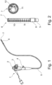
- Fig. 1 shows a perspective view of an endoscope 1 according to the disclosure.
- the endoscope 1 shown has a proximal endoscope operating section or endoscope handle 2 with operating elements or wheels 3 and a Luer connection 4.
- a flexible shaft 5 extends distally from the endoscope operating section or endoscope handle 2.
- a distal endoscope section 6 is controllable to pivot and rotate an endoscope head 7, which forms a distal end of the endoscope 1.
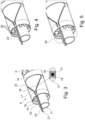
- Fig. 2 shows the distal endoscope section 6 of the endoscope after Fig. 1 .
- a rotary mechanism 8 according to the disclosure is mounted on a distal end of the shaft 5, which is described in more detail below with reference to the other figures.
- a distal end of the rotary mechanism 8 is connected to a deflection 9, which, as shown here by way of example, has several wedge-shaped segments that are hinged to one another on their wide side and can be folded together towards their narrow side in order to bend the deflection 9.
- a folding mechanism 10 is mounted on the distal end of the deflection 9, which, as shown here by way of example, has several wedge-shaped segments that have a larger wedge angle than the segments of the deflection 9 in order to achieve a narrower angle of curvature than the deflection 9.
- the segments of the folding mechanism 10 are connected to one another and to the deflection 9 via the connecting plate.
- the deflection 9 and the folding mechanism 10 can also be designed differently.
- the endoscope head 7 is mounted at the distal end of the folding mechanism 10.
- the folding mechanism 10 can be considered as part of the endoscope head 7.
- Fig. 2 also shows a top view of the endoscope head 7 of the endoscope 1. This forms an outlet of a working channel 11 as well as other elements such as a camera or optics 12.
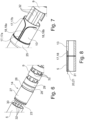
- Fig.3, 4 and 5 show the rotating mechanism 8 after Fig. 1 and 2 in different assembly states, whereby for reasons of clarity in Fig. 4 and 5 only reference numerals of additional, in the previous figures (ie Fig. 3 or Fig. 3 and 4 ) elements not shown are inserted. The remaining elements correspond to the elements shown in the previous figures.
- the rotating mechanism 8 has a base sleeve 13 which is designed for mounting on the distal end of the shaft 5. Inserted into the base sleeve 13 and mounted so as to be rotatable thereto is a rotating sleeve 14, the distal end of which projects beyond a distal end of the base sleeve 13 and is designed for mounting on the deflecting 9.
- a holding or positioning ring 15 is arranged axially fixed, in particular fastened, e.g. glued, on a proximal section of an inner side of the base sleeve 13.
- the holding or positioning ring 15 is arranged proximally from the rotary sleeve 14 or from a step of the rotary sleeve 14 in order to form a stop for the rotary sleeve 14 in the proximal direction. This means that the rotary sleeve 14 can be inserted into a distal end of the base sleeve 13, at most until a proximal end or the step of the rotary sleeve 14 strikes the holding or positioning ring 15.
- the rotary sleeve forms axial channels or openings 16 through which the working channel 11 (in Fig. 3, 4 and 5 a part of it is shown as a tubular intermediate piece) and possibly further lines 32 (in Fig. 3, 4 and 5 not shown), are held in a fixed position in the rotating sleeve 14 and guided in the axial direction through the rotating sleeve 14.
- the base sleeve 13 forms a first guide section 17 in the form of a groove- or slot-shaped receptacle, the proximal end section 17a of which preferably runs parallel to a shaft longitudinal axis of the shaft 5. Further distally, the first guide section 17 or the groove- or slot-shaped receptacle bends and then runs obliquely in its/her middle section and distal end section 17b, ie it extends distally along and in a first circumferential direction around the base sleeve 13.
- the base sleeve 13 forms a second guide section 18 in the form of a groove- or slot-shaped receptacle, the proximal End section 18a preferably runs parallel to the longitudinal axis of the shaft 5. Further distally, the second guide section 18 or the groove- or slot-shaped receptacle makes a bend and then runs in its/its middle section and distal end section 18b obliquely distally and in a second circumferential direction opposite to the first circumferential direction such that it moves away from the first guide section 17.
- first guide section 17 and the second guide section 18 are arranged essentially in a Y-shape to one another, with the proximal end sections 17a, 18a of the first and second guide sections 17, 18 forming a foot of the Y-shape and the middle sections and distal end sections 17b, 18b of the first and second guide sections 17, 18 forming arms of the Y-shape.
- a capillary tube 19 is attached, as shown in Fig. 3 is schematically illustrated in a detailed view of the second guide section 18.
- a proximal or distal passage is formed, which deflects or opens the respective guide section 17, 18 radially inward in order to guide the first or second cables 20, 21 guided therein radially inward, as described in more detail below.
- the respective proximal and/or distal passages can be formed in that the corresponding distal and/or proximal end of the first and/or second guide sections 17, 18 is free of the capillary tubes 19, so that the respective groove- or slot-shaped receptacle of the first and/or second guide sections 17, 18 is connected at least to the inner peripheral surface of the base sleeve 13.
- the respective proximal and/or distal passages may be formed by portions of the capillary tubes 19 being bent radially inward at the distal and/or proximal ends of the first and/or second guide portion.
- a first cable 20 is guided through the shaft 5 and is introduced from an inner side of the base sleeve 13 through the proximal passage provided there into the capillary tube 19 held in the first guide section 17.
- the first cable 20 is deflected in the circumferential direction by the first guide section 17 and exits at the distal end of the first guide section 17 through the distal Passage to the inside of the base sleeve 13 in order to reach the rotary sleeve 14 there, as will be described in more detail later.
- a second cable 21 is guided through the second guide section 18 in a distal direction and towards the rotary sleeve 14, corresponding to the first cable 20. Distal end sections of the first and second cables 20, 21 are attached to the rotary sleeve 14 and can be wound onto and unwound from it, as will be described in more detail later.
- a cover film or cover sleeve 22 is provided radially on the outside, which sits radially on the outside of the base sleeve 13 and at least partially covers the first and second guide sections from the radial outside.
- a locking plate or cover plate 23 is mounted, which is inserted into the base sleeve 13 proximal to the holding or positioning ring 15 and is connected to the rotating sleeve 14 in a rotationally fixed manner, e.g. screwed.
- the holding or positioning ring 15 forms a stop for the locking plate or cover plate 23 in the distal direction. This means that when the rotating sleeve 14 is connected to the locking plate or cover plate 23, an axial movement of the rotating sleeve 14 relative to the base sleeve 13 is essentially prevented by the holding or positioning ring 15.
- the rotating sleeve 14 is thus rotatably mounted together with the locking plate or cover plate 23 in the base sleeve 13 and is fixed in position in the axial direction by the holding or positioning ring 15.
- the rotating mechanism 8 thus forms a pre-assembled component.
- the proximal passages of the first and second guide sections 17, 18 are arranged proximally from the locking plate or cover plate 23 or are partially defined by it.
- the locking plate or cover plate 23 also forms through openings 24 for the lines 32 and the working channel 11 in order to determine their position in the rotary sleeve 14.
- a connecting ring or transition body 25 is provided, which is arranged proximally from the base body 13 in order to connect it to the shaft 5, e.g. by clamping, screwing, gluing or the like.
- the connecting ring or transition body 25 covers the proximal passages of the first and second guide sections 17, 18 and rests at its distal end directly on the cover film or cover sleeve 22.
- Fig. 6 shows the rotating sleeve 14 of the rotating mechanism 8 in its position between the shaft 5 and the deflecting 9 as well as the lines 32 passing through these three components.
- the rotating sleeve 14 can rotate the rotating sleeve according to Fig. 3 but can also belong to a second embodiment.
- the locking plate or end disk 23 is fastened proximally to the rotary sleeve 14.
- the rotary sleeve 14 has a positioning section 26 with a diameter which is reduced with respect to a distally adjacent bearing section 27 and the locking plate or end disk 23 in order to provide a receptacle and stops for the holding or positioning ring 15.
- the rotary sleeve 14 is rotatably mounted on the base sleeve 13 via the bearing section 27.
- a circumferential, annular drive groove or ring groove 28 is formed distally from the bearing section. This is designed to receive and fasten the first and second cables 20, 21, which can thus be wound up and unwound around/from the rotary sleeve 14 in the drive groove or ring groove 28.
- the cables 20, 21 can, for example, be glued into radial holes shown schematically here as dots in the drive groove or annular groove 28.
- a distal end of the rotary sleeve 14 forms a fastening section 29, which is designed to fasten the deflecting 9.
- a collar 30 is formed between the drive groove or annular groove 28 and the fastening section 29, which defines a mounting position for the deflecting 9 on its distal side and a mounting position for the cover film or cover sleeve 22 on its proximal side.
- Fig. 7 shows a base sleeve 14 and a connecting ring or transition body 25 of the rotary mechanism 8 according to the second embodiment.
- This base sleeve 14 differs from the base sleeve 14 of the first embodiment essentially by the shape of the first and second groove-shaped guide sections 17, 18, which are groove-shaped or slot-shaped receptacles. These run, as in Fig. 7 shown, in a proximal and a middle region of the guide sections 17, 18 essentially parallel to each other and to the shaft axis and only curve in the circumferential direction at their distal end region. At their distal ends, the guide sections 17, 18 or the groove- or slot-shaped receptacles run essentially exactly in the circumferential direction, so that the guide sections 17, 18 essentially describe a 90° curve.
- Fig. 8 shows schematically an arrangement of the shaft 5 relative to the base sleeve 13 in a longitudinal section which runs through a proximal end of the first or second guide section 17, 18.
- the shaft 5 forms, at least at its distal end region, a grooved, flat or slotted cable receptacle 31 in which the first and second cables 20, 21 are received.
- the cables 20, 21 therefore do not interfere with movement of the lines 32 and the working channel 11 within the shaft 5.
- the cables can also be guided within the shaft 5 in a common or two separate sheaths.
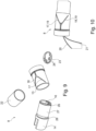
- Fig. 9 shows a perspective view of the individual components of the rotary mechanism according to a third embodiment.
- a difference between this embodiment and the first embodiment is that no separate connecting ring or transition body 25 is provided, but rather it is formed integrally with the base sleeve 13.
- the first and second guide sections 17, 18 or the groove- or slot-shaped receptacles are formed at their proximal ends running parallel to the shaft axis as a single, common groove- or slot-shaped receptacle, which only divides further distally into the first and second guide sections 17, 18 in a Y-shape.
- the guide sections 17, 18 or the groove- or slot-shaped receptacles are closed radially on the inside, apart from the proximal and distal passages.
- Fig. 10 shows the rotation mechanism Fig. 8 in the assembled state.
- the first and second cables 20, 21 are inserted into the guide sections 17, 18 or into the capillary tubes held or fastened therein.
Landscapes
- Health & Medical Sciences (AREA)
- Life Sciences & Earth Sciences (AREA)
- Surgery (AREA)
- Biomedical Technology (AREA)
- Medical Informatics (AREA)
- Optics & Photonics (AREA)
- Pathology (AREA)
- Radiology & Medical Imaging (AREA)
- Biophysics (AREA)
- Engineering & Computer Science (AREA)
- Physics & Mathematics (AREA)
- Heart & Thoracic Surgery (AREA)
- Nuclear Medicine, Radiotherapy & Molecular Imaging (AREA)
- Molecular Biology (AREA)
- Animal Behavior & Ethology (AREA)
- General Health & Medical Sciences (AREA)
- Public Health (AREA)
- Veterinary Medicine (AREA)
- Endoscopes (AREA)
- Instruments For Viewing The Inside Of Hollow Bodies (AREA)
Description
- Die vorliegende Offenbarung betrifft ein Endoskop mit einem im Wesentlichen schlauchförmigen proximalen Schaft, welcher zum Einführen in einen Patientenkörper ausgebildet ist und sich entlang einer Schaftachse erstreckt, einem im Wesentlichen schlauchförmigen Lenkabschnitt, welcher distal vom Schaft angeordnet ist und bezüglich der Schaftachse abkrümmbar ist, einem Endoskopkopf, welcher distal vom Lenkabschnitt angeordnet ist und eine Optik und einen Arbeitskanalausgang aufweist, und einem Drehmechanismus, welcher dazu konfiguriert ist, den Lenkabschnitt bezüglich des Schafts um die Schaftachse zu drehen.
- Endoskope sind medizinische Arbeitsgeräte zur visuellen Exploration von Hohlräumen in einem Patientenkörper. Sie weisen grundsätzlich optische Einrichtungen am distalen, d.h. Anwender-abgewandten bzw. Patientenkörper-zugewandten, Endoskopkopf, einen proximalen, d.h. Anwender-zugewandten, Endoskopbedienabschnitt oder Endoskopgriff und einen flexiblen oder biegesteifen (starren) Schaft auf, welcher den Endoskopkopf und den proximalen Endoskopbedienabschnitt oder Endoskopgriff verbindet. In der Regel hat das Endoskop ferner einen Arbeitskanal, welcher sich vom proximalen Endoskopbedienabschnitt durch den Schaft zu einem am Endoskopkopf gebildeten Arbeitskanalausgang erstreckt und das extrakorporale Einführen und Verwenden eines medizinischen Instruments wie z.B. einer Zange, Schere, Nadel, Schlinge, Messer und dergleichen ermöglicht. Viele Endoskope haben ferner Deflectings, d.h. einen steuerbaren Schaftabschnitt, welcher zwischen dem Schaft und dem Endoskopkopf angeordnet ist, um ein Steuern des Endoskops in einem Patientenhohlraum zu ermöglichen.
- Derartige Endoskope können wahlweise mit zusätzlichen Fähigkeiten versehen werden, etwa indem am distalen Endoskopende/Endoskopkopf eine Kappe oder Hülse auf den Endoskopkopf radial außenseitig aufgesetzt wird, die mit bestimmten Funktionen/Funktionselementen versehen oder ausgerüstet ist, wodurch das Endoskop nicht nur zur Exploration und/oder als Zugang für therapeutische Anwendungen sondern auch selbst als ein minimalinvasives Instrument zur Ausführung eines chirurgischen Vorgangs genutzt werden kann. Alternativ hierzu ist es aber auch vorgesehen, spezielle Endoskope für ganz bestimmte medizinische Anwendungen mit derartigen Fähigkeiten integral auszustatten, wobei derartige Spezialanfertigungen jedoch nur für diese besondere Anwendung geeignet sind.
- Verschiedene diagnostische und/oder therapeutische Verfahren erfordern beispielsweise eine Bildgebung und/oder bei Bedarf therapeutische Techniken am Gallen- und/oder Bauchspeicheldrüsengang sowie den Lebergängen des Patienten. Da die Vatersche Papille, welche den gemeinsamen Austritt von Gallen- und Bauchspeicheldrüsengang in das Duodenum bildet, seitlich in das Duodenum hineinragt, sind herkömmliche prograde (in Endoskop-Längsrichtung blickende) Endoskope für das Heran- und Einführen von chirurgischen Instrumenten in den Gallenkanal ungeeignet, da nicht genügend Schwenkraum im engen Duodenum (Durchmesser 3 bis 4 cm) vorhanden ist, um deren prograde Optik sowie den Arbeitskanal in eine seitwärts blickende Position auszurichten, da ein typischer Biegeradius solcher Geräte bei etwa 6 cm liegt. Dieser Biegeradius bzw. diese Verschwenkung wird bei herkömmlichen prograden Endoskopen häufig durch sogenannte "Deflectings", d.h. zwischen dem Schaft und dem Endoskopkopf angeordnete, insbesondere dem Endoskopkopf unmittelbar in Richtung proximal vorgeordnete, aktiv abkrümmbare Schaftabschnitte erzielt.
- Aus dem Stand der Technik (bspw. der
US 2010/228086 A ) sind zu diesem Zweck speziell angefertigte Duodenoskope bekannt, welche eine laterale (seitwärts blickende) oder retrograde (rückblickende) Optik (auch "Seitoptik" genannt) sowie einen seitwärts gerichteten bzw. sich öffnenden Arbeitskanal aufweisen. Alternativ hier kann an einem prograden (in Axialrichtung sich öffnenden) Ausgang des Arbeitskanals solcher Duodenoskope ein sogenannter Albarranhebel vorgesehen sein, der durch manuell bewirktes Verschwenken ein gezieltes Führen/Umlenken eines im Arbeitskanal geführten Instruments ermöglicht. Durch die seitwärts gerichtete Anordnung der Funktionseinheiten insbesondere Optik und Beleuchtung am Endoskopkopf wird eine Bildgebung und Behandlung im Bereich des Duodenums unter optimaler Nutzung des zur Verfügung stehenden Raums ermöglicht. - Derartige Endoskope mit Seitoptik sind jedoch sehr aufwendig und teuer in ihrer Fertigung und werden deshalb bislang als wiederverwendbare Geräte entwickelt und hergestellt. Der gekrümmte Arbeitskanal solcher Endoskope sowie die komplexe und hinterschnittreiche Konstruktion des Albarranhebels haben sich in der Praxis zudem als schwer sterilisierbar erwiesen. Dadurch ist ein Risiko für eine Kontamination des Endoskops und dadurch bedingt die Kontamination einer Operationsstelle oder eines Hohlraums eines Patienten erhöht, bei welchem das Endoskop eingesetzt wird. Dadurch kann es an der Operationsstelle oder in dem Hohlraum zu schwerwiegenden Entzündungen bis hin zu einer Sepsis kommen. Weiter haben solche Geräte den Nachteil, dass sie nur für wenige, sehr spezifische Eingriffe im Bereich des Duodenums eingesetzt werden können, da weder die Optik noch der Arbeitskanal in prograde Richtung gerichtet werden können. Die Navigation im Patientenkörper insbesondere in engen Patientenhohlräumen ist somit mit seitwärts blickenden Endoskopen im Allgemeinen eher schwierig.
- Des Weiteren ist aus
DE 10 2018 110 620 A1 ein Abklappmechanismus zur abklapp- oder abwinkelbaren Halterung eines Endoskopkopfes bekannt, mit einer Anzahl axial aufeinanderfolgender und mittels eines Betätigungselements aktiv d.h. manuell kontrolliert gegeneinander winkelverstellbarer Segmente. Durch diese Konstruktion ist es möglich, den distalen Endoskopkopf in einem sehr engen Radius in eine Radialausrichtung zu verschwenken, derart, dass die distale Stirnseite des Endoskopkopfs nicht oder nur geringfügig über den Außenumfang des Endoskopschafts radial vorragt. Nachteilig an diesem Mechanismus ist jedoch, dass ein solcher Mechanismus nur dazu geeignet ist, in einer einzigen bestimmten Richtung abzuklappen und somit die Anwendungsbreite des zugehörigen Endoskops beschränkt ist. Zudem kann es problematisch sein, wenn der Abklappmechanismus an der zu begutachtenden Stelle im Patientenhohlraum falsch ausgerichtet ist. -
WO 2012/070781 A2 offenbart einen Drehmechanismus, der einen flexiblen Endoskopschaft mit einem distal dazu angeordneten Biegemechanismus um die Schaftachse zueinander verdrehbar verbindet, wobei verschiedene Antriebe bereitgestellt sind. Diese Antriebe sind jedoch sehr aufwändig und benötigen viel Platz und/ oder sind, wie zum Beispiel im Fall eines Antriebs über ein Seil, fehleranfällig und fragil. - Ein weiterer Drehmechanismus, der einen Seilzug verwendet, ist aus der
WO 2021/079 221 A1 bekannt. Bei diesem Drehmechanismus ist das Seil an einer Drehhülse über Ösen umgelenkt. - Weiterer Stand der Technik ist aus der
DE 10 2004 058 929 A1 oder derJP 2009 112 536 A - Die der Offenbarung zugrundeliegende Aufgabe ist es, Nachteile des Stands der Technik zu vermeiden oder zu reduzieren. Insbesondere soll ein Endoskop mit einem steuerbaren Endoskopkopf und einem einfachen, robusten Drehantrieb bereitgestellt werden.
- Die Aufgabe wird gelöst durch ein Endoskop nach Anspruch 1. Vorteilhafte Ausgestaltungen sind Gegenstand der Unteransprüche.
- Genauer wird die Aufgabe gelöst durch ein Endoskop mit einem im Wesentlichen schlauchförmigen Schaft, welcher zum Einführen in einen Patientenkörper ausgebildet ist und sich entlang einer Schaftachse erstreckt, einem Endoskopkopf, welcher distal vom Schaft angeordnet ist, bezüglich der Schaftachse abkrümmbar oder abklappbar ist und eine Kamera sowie einen Ausgang eines Arbeitskanals aufweist, einem Drehmechanismus, welcher zwischen dem Endoskopkopf und dem Schaft angeordnet und dazu konfiguriert ist, den Endoskopkopf bezüglich des Schafts um die Schaftachse zu drehen. Der Drehmechanismus hat eine Basishülse, welche bezüglich der Schaftachse drehfest mit dem Schaft verbunden ist, und eine Drehhülse, welche bezüglich der Schaftachse drehfest mit dem Endoskopkopf oder einem zwischenliegenden Abschnitt verbunden ist, wobei die Drehhülse und die Basishülse ineinander geschachtelt sind. Der Drehmechanismus hat ferner ein erstes Seil mit einem distalen Seilabschnitt, welcher an der Drehhülse derart befestigt ist, dass das erste Seil um die Drehhülse aufwickelbar oder abwickelbar ist, wobei die Basishülse in ihrer Seitenwand oder an/ in einer der Drehhülse radial gegenüberliegenden (d.h. entgegengesetzten) Fläche der Seitenwand einen ersten Führungsabschnitt in Form einer rillen- oder schlitzförmigen Aufnahme bildet, in welchem das erste Seil geführt ist. Insbesondere ist die rillen- oder schlitzförmige Aufnahme zumindest an einer der Drehhülse zugewandten Seite geschlossen, z.B. durch einen integralen Wandabschnitt der Basishülse und/ oder durch einen zur Basishülse separat ausgebildetes, aber fest damit verbundenen Wandabschnitt. Ein solcher separater, aber fest mit der Basishülse verbundener Wandabschnitt kann z.B. ein in die rillen- oder schlitzförmige Aufnahme der Basishülse (z.B. durch Löten, Kleben oder dergleichen) fest eingesetzter Wandabschnitt, wie z.B. ein Röhrchen, in dem das erste Seil geführt ist, sein. An einem distalen Ende des ersten Führungsabschnitts bildet die Basishülse einen ersten distalen Durchgang, durch welches das erste Seil aus dem ersten Führungsabschnitt zur Drehhülse geführt ist. D.h. der Durchgang verbindet die rillen- oder schlitzförmige Aufnahme bzw. ggf. ein darin eingesetztes Element, wie das Röhrchen, mit einer der Drehhülse zugewandten Seite des Basiselements, sodass das Seil aus der rillen- oder schlitzförmige Aufnahme durch den Durchgang zur Drehhülse geführt wird. Insbesondere kann der Durchgang ein Loch in dem integralen oder dem separaten, aber fest mit der Basishülse verbundenen Wandabschnitt sein. Alternativ kann der Durchgang durch eine Lücke zwischen einem distalen Ende der rillen- oder schlitzförmige Aufnahme und einem distalen Ende des darin eingesetzten, separaten, Wandabschnitts (z.B. einem distalen Ende des Röhrchens) sein. Dort kann das erste Seil um die Drehhülse gewickelt sein.
- In anderen Worten ausgedrückt ist ein Endoskop bereitgestellt, welches einen Schaft und einen distalen Endoskopabschnitt mit einem abkrümmbaren oder abklappbaren Endoskopkopf und einem Drehantrieb zwischen dem Schaft und dem distalen Endoskopabschnitt aufweist. Der Drehantrieb ist ein Seilantrieb, welcher darauf basiert, dass ein erstes Seil bereitgestellt ist, welches in Umfangsrichtung auf eine Drehhülse (auch als Spule bezeichenbar) aufgewickelt ist, und durch einen Zug am ersten Seil ein Abwickeln des ersten Seils und dadurch eine Drehung der Drehhülse erreicht wird. Die Drehhülse ist hierzu drehbar und bevorzugt axialfest an einer Basishülse gelagert, welche den Drehmechanismus mit dem Schaft verbindet.
- Angaben wie "axial", "Umfangsrichtung" und "radial" beziehen sich stets auf die Schaftachse. Der Schaft kann starr oder flexibel sein. Der Endoskopkopf kann ferner eine Beleuchtungseinrichtung und/oder eine Spüleinrichtung und/oder weitere Elemente aufweisen, welche mit zugehörigen Leitungen verbunden sind. Ineinander geschachtelt heißt, dass die beiden Hülsen (Drehhülse und Basishülse) sich axial zumindest teilweise überlappen bzw. dass eine der beiden Hülsen in die andere der beiden Hülsen eingesteckt ist.
- Der Drehmechanismus wird betätigt, indem am ersten Seil gezogen wird, welches um die Drehhülse gewickelt ist. Dadurch wickelt sich das Seil von der Drehhülse ab und treibt diese in Umfangsrichtung, d.h. drehend, an. Der Endoskopkopf ist insbesondere bezüglich der Schaftachse abklappbar oder krümmbar, insbesondere zu genau einer Seite hin (d.h. in einer einzelnen Radialrichtung).
- Der Drehmechanismus des vorstehenden Endoskops hat eine besonders einfache Konfiguration und ist somit kostengünstig herzustellen. Ferner ist der Drehmechanismus reibungsarm und somit einfach zu bedienen. Zudem ist das erste Seil besonders sicher geführt und umgelenkt, sodass es sicher geführt wird. Ein Risiko, dass das Seil reißen könnte, ist somit minimiert.
- Bevorzugt ist ein zweites Seil bereitgestellt, welches durch einen zweiten Führungsabschnitt in Form einer rillen- oder schlitzförmigen Aufnahme in der Basishülse in Richtung distal verlaufend geführt ist und in einer zum ersten Seil entgegengesetzten Umfangsrichtung um die Drehhülse gewickelt oder wickelbar ist. Bevorzugt bildet die Basishülse am distalen Ende des zweiten Führungsabschnitts einen zweiten distalen Durchgang, welcher in Umfangsrichtung zum ersten Durchgang beabstandet ist und durch welchen das zweite Seil hindurchgeführt ist.
- In anderen Worten ausgedrückt verlaufen der zweite Führungsabschnitt und das zweite Seil spiegelbildlich zum ersten Führungsabschnitt und dem ersten Seil. Dadurch kann besonders einfach und zuverlässig ein Antrieb der Drehhülse in beide Drehrichtungen bereitgestellt werden. D.h., je nachdem, an welchem der beiden Seile (dem ersten oder zweiten Seil) gezogen wird, wird die Drehhülse in unterschiedliche Richtungen gedreht. Zumindest eines der beiden Seile ist bei dieser Ausgestaltung stets um die Drehhülse gewickelt. In einer neutralen Position sind beide Seile zu zumindest 180° um die Drehhülse gewickelt.
- Bevorzugt ist das erste und/oder das zweite Seil dazu ausgebildet und dimensioniert, dass es mindestens um 360° um die Drehhülse gewickelt oder wickelbar ist. Somit kann eine vollständige Drehung des Endoskopkopfs erreicht werden. Die Drehhülse kann ein oder mehrere Befestigungslöcher, insbesondere Radialbohrungen, aufweisen, in welchen das erste und/oder das zweite Seil befestigt ist. Dies ermöglicht eine einfache und sichere Befestigung der Seile an der Drehhülse.
- Bevorzugt ist das erste und/oder das zweite Seil jeweils in einem Kapillarrohr geführt, welches im oder am ersten bzw. zweiten Führungsabschnitt der Basishülse im Wesentlichen lagefest angebracht ist. Dadurch kann das erste und/oder zweite Seil besonders sicher im jeweiligen Führungsabschnitt gehalten werden. Ein Herausspringen aus dem jeweiligen Führungsabschnitt unter Zug und ein dadurch bedingtes Verklemmen zwischen der Basishülse und einem anderen Bauteil kann somit vermieden werden. Das Kapillarrohr kann z.B. eine Wandstärke von 0,4 mm haben und im ersten bzw. zweiten Führungsabschnitt befestigt, z.B. eingeklebt oder eingelötet sein.
- Bevorzugt ist der erste und/oder zweite Führungsabschnitt an einer radialen Außenseite der Basishülse offen, insbesondere entlang seiner gesamten Läge. Dadurch ist eine Montage des ersten bzw. zweiten Seils und ggf. der Kapillarrohre im jeweiligen Führungsabschnitt besonders einfach.
- Bevorzugt verläuft zumindest ein Abschnitt des ersten und/ oder zweiten Führungsabschnitts unmittelbar proximal zum ersten bzw. zweiten Durchgang schräg oder quer zur Schaftachse. Dies ermöglicht eine besonders schonende Umlenkung des jeweiligen Seils, sodass Kräfte, welche beim Zug am Seil aufgrund einer Umlenkung der Kraft von distaler in Umfangsrichtung durch das Seil besser abgestützt werden. Ein Risiko, dass das jeweilige Seil reißen könnte, wird somit minimiert. Bevorzugt verläuft ein proximaler Abschnitt des ersten und/oder zweiten Führungsabschnitts parallel zueinander und zur Schaftachse. Die proximalen Abschnitte können auch miteinander verbunden sein und durch eine gemeinsame nut-, rillen- oder schlitzförmige Aufnahme gebildet sein. Bevorzugt entfernen sich in einem distalen Bereich der Führungsabschnitte (d.h. jeweils der Abschnitt des ersten und/ oder zweiten Führungsabschnitts unmittelbar proximal zum ersten bzw. zweiten Durchgang) die Führungsabschnitte in Umfangsrichtung voneinander. In andere Worten verläuft bevorzugt der zweite Führungsabschnitt zumindest im Abschnitt unmittelbar proximal zur zweiten Durchgangsöffnung schräg oder quer zur Schaftachse mit einer zum ersten Führungsabschnitt entgegengesetzten Neigung bzw. Umfangsrichtung. Ein Übergang zwischen dem parallel zur Schaftachse verlaufenden Bereich und dem schräg oder quer zur Schaftachse verlaufenden Bereich des ersten und/ oder zweiten Führungsabschnitts kann kurven- oder knickförmig ausgestaltet sein.
- Bevorzugt bildet der erste und/ oder zweite Führungsabschnitt jeweils an seinem proximalen Ende einen proximalen Durchgang, in welchem das erste bzw. zweite Seil aus dem ersten bzw. zweiten Führungsabschnitt nach radial innen geführt ist.
- Bevorzugt bildet die Drehhülse oder ggf. auch die Basishülse an einer bestimmten Axialposition, welche einer Axialposition der ersten und zweiten Durchgänge entspricht, eine Antriebsrille oder Ringnut, welche zur Aufnahme des ersten und zweiten Seils ausgebildet ist. Somit können die Seile an einer bestimmten Position aufgewickelt werden und laufen nicht Gefahr, sich zwischen den beiden Hülsen zu verklemmen. Zudem kann somit besonders einfach Platz für eine Befestigung des ersten und/oder zweiten Seils an der Drehhülse bereitgestellt werden. D.h., das erste und/ oder zweite Seil ist bevorzugt innerhalb der Antriebsrille oder Ringnut an der Drehhülse befestigt.
- Bevorzugt ist die Basishülse eine radial äußere Hülse ist und die Drehhülse eine radial innere Hülse. Dies ermöglicht eine besonders einfache Montage. Zudem ist ein Abschnitt des Endoskops, dessen radial äußere Elemente sich drehen und ggf. Gewebe des Patienten schädigen könnten, minimiert. Der Drehmechanismus kann ferner eine Schutz- oder Deckhülse oder Schutz- oder Deckfolie als eine radial äußerste Schicht haben. Dadurch kann der erste und/ oder zweite Führungsabschnitt radial außenseitig abgedeckt oder verschlossen werden, um eine Kontamination oder ein Einbringen von Störkörpern in den Drehmechanismus zu unterbinden sowie eine Gefahr, das Gewebe zu verletzen, zu minimieren.
- Bevorzugt hat das Endoskop elektrische, hydraulische und/ oder leere Leitungen sowie einen Arbeitskanal (d.h., Schläuche und Kabel), welche sich durch den Schaft und den Drehmechanismus zum oder durch den Endoskopkopf erstrecken. Insbesondere stellt der Drehmechanismus an seinem proximalen Bereich, insbesondere angrenzend an den Schaft, einen Halte- oder Positionierungsring bereit, welcher eine Lage der Leitungen bezüglich der Drehhülse bestimmt. Auf diese Wiese kann ein Überkreuzen der Schläuche und Kabel beim Drehen des Drehmechanismus verhindert werden. In anderen Worten wird eine geordnete Verlegung der Schläuche und Kabel erreicht.
- Bevorzugt bildet der Schaft an seinem distalen Ende einen Hohlraum, welcher sich in Richtung distal öffnet und derart dimensioniert ist, dass Platz für eine Drehung und/ oder Umfangsbewegung der Leitungen und des Arbeitskanals ist, welche durch den Schaft zum Endoskopkopf verlaufen und sich in einem distalen Bereich zusammen mit der Drehhülse drehen bzw. dass die Leitungen zwischen verschiedenen, von einer Drehstellung der Drehhülse abhängigen Positionen beweglich sind. Somit kann eine besonders reibungsarme, wenig störungsanfällige Bedienung gewährleistet werden.
- Bevorzugt hat der Schaft zumindest an seinem distalen Ende eine nut-, rillen- oder schlitzförmige, sich in Richtung distal öffnende Seilaufnahme, in welcher das erste und/ oder das zweite Seil geführt ist. D.h. das erste und/ oder zweite Seil wird in einem (radialen) Mantelbereich des Schafts in den Schaft eingeführt. Auf diese Wiese kommen das erste und/ oder zweite Seil, welche sich nicht zusammen mit der Drehhülse drehen, nicht den sich drehenden/ bewegenden Leitungen in die Quere und eine besonders reibungsarme, wenig störungsanfällige Bedienung kann gewährleistet werden. Das erste und/ oder zweite Seil kann innerhalb des Schafts in einer Hülle geführt sein. Dadurch können Differenzlängen der Seile vermieden werden, welche sich beim Krümmen des Schafts ergeben könnten. Bevorzugt sind ferner die Leitungen in einem distalen Schaftabschnitt in Umfangsrichtung beweglich sind und mit einer Gleitschicht oder einer Gleithülle ummantelt. Dies ermöglicht es weiter, Reibung zu minimieren, welche durch das Drehen und Bewegen der Leitungen und des Arbeitskanals relativ zum distalen Schaftbereich entstehen. Es kann also eine besonders reibungsarme, wenig störungsanfällige Bedienung gewährleistet werden.
- Weiter bevorzugt ist distal vom Drehmechanismus und proximal vom Endoskopkopf ein Deflecting zum Lenken eines distalen Endoskopabschnitts bereitgestellt. Ein Deflecting ist ein zumindest zu einer Seite hin bezüglich der Schaftachse abkrümmbarer Schaftabschnitt, welcher über einen Steuerdraht betätigbar ist. Das Deflecting hat insbesondere mehrere zueinander abwinkelbar verbundene Segmente, die bevorzugt keilförmig sind. Ferner hat das Endoskop bevorzugt einen Abklappmechanismus, welcher zwischen dem Drehmechanismus, bevorzugt distal vom Deflecting, und dem Endoskopkopf angeordnet ist oder durch den Endoskopkopf gebildet wird und ein Abklappen des Endoskopkopfs bezüglich der Schaftachse ermöglicht. Der Abklappmechanismus ist bevorzugt durch einen separaten Steuerdraht, insbesondere unabhängig vom Deflecting, betätigbar. Ein maximaler Abklappwinkel des Abklappmechanismus ist bevorzugt kleiner als ein maximaler Krümmungswinkel des Deflectings.
- Bevorzugt sind das erste und/ oder das zweite Seil als Antriebsseil ausschließlich zum Antrieb der Drehhülse bereitgestellt. Bevorzugt sind das erste und/ oder das zweite Seil separat von Steuerdrähten zum Antrieb einer Lenkung des Endoskopkopfs bereitgestellt, insbesondere separat zum Antrieb des Deflectings und/ oder des Abklappmechanismus. Bevorzugt sind das erste und das zweite Seil an einer im proximalen Bedienabschnitt oder Endoskopgriff bereitgestellten Seilrolle geführt und bedienbar. Vorzugsweise sind das erste und das zweite Seil an ihren proximalen Enden miteinander verbunden.
- Bevorzugt sind die sämtliche Teile des Drehmechanismus derart aneinander montiert, dass diese eine unabhängig vom Schaft und/oder dem Endoskopkopf zusammenhängende Baugruppe bilden. Somit kann der Drehmechanismus vormontiert und als fertige Baugruppe einfach und kostengünstig am Schaft und am distalen Endoskopabschnitt befestigt werden.
- Nachfolgend wird die vorliegende Offenbarung anhand von bevorzugten Ausführungsformen beschrieben. Diese sind jedoch nur veranschaulichender Natur und sollen den Schutzumfang der vorliegenden Offenbarung nicht einschränken. Ferner werden bei der Beschreibung der verschiedenen Ausführungsformen für gleiche Bauteile dieselben Bezugszeichen verwendet.
-
Fig. 1 zeigt eine perspektivische Darstellung eines offenbarungsgemäßen Endoskops. -
Fig. 2 zeigt einen distalen Endoskopabschnitt des Endoskops nachFig. 1 sowie eine Draufsicht auf einen Endoskopkopf des Endoskops. - Figen. 3, 4 und 5 zeigen schematisch einen Drehmechanismus des Endoskops nach
Fig. 1 und 2 in verschiedenen Montagezuständen. -
Fig. 6 zeigt eine Drehhülse des Drehmechanismus gemäßFig. 3 . -
Fig. 7 zeigt eine Basishülse des Drehmechanismus nach einer zweiten Ausführungsform. -
Fig. 8 zeigt schematisch eine Anordnung eines Schafts und einer Basishülse. -
Fig. 9 zeigt eine perspektivische Darstellung der einzelnen Bauteile des Drehmechanismus nach einer dritten Ausführungsform. -
Fig. 10 zeigt den Drehmechanismus nachFig. 8 im zusammengebauten Zustand. -
Fig. 1 zeigt eine perspektivische Darstellung eines offenbarungsgemäßen Endoskops 1. Das dargestellte Endoskop 1 hat einen proximalen Endoskopbedienabschnitt oder Endoskopgriff 2 mit Bedienelementen oder -rädern 3 und einem Luer-Anschluss 4. Vom Endoskopbedienabschnitt oder Endoskopgriff 2 erstreckt sich ein flexibler Schaft 5 in distaler Richtung. Ein distaler Endoskopabschnitt 6 ist steuerbar, um einen Endoskopkopf 7 zu verschwenken und zu drehen, welcher ein distales Ende des Endoskops 1 bildet. -
Fig. 2 zeigt den distalen Endoskopabschnitt 6 des Endoskops nachFig. 1 . An einem distalen Ende des Schafts 5 ist ein offenbarungsgemäßer Drehmechanismus 8 montiert, welcher nachstehend mit Verweis auf die übrigen Figuren genauer beschrieben wird. Ein distales Ende des Drehmechanismus 8 ist mit einem Deflecting 9 verbunden, welches, wie hier beispielhaft dargestellt, mehrere keilförmige Segmente hat, die an ihrer breiten Seite aneinander angelenkt sind und zu ihrer schmalen Seite hin zusammengeklappt werden können, um das Deflecting 9 zu krümmen. Am distalen Ende des Deflectings 9 ist ein Abklappmechanismus 10 montiert, welcher, wie hier beispielhaft dargestellt, mehrere keilförmige Segmente hat, die einen größeren Keilwinkel aufweisen als die Segmente des Deflectings 9, um einen engeren Krümmungswinkel als das Deflecting 9 zu erreichen. Die Segmente des Abklappmechanismus 10 sind über die Verbindungsplatte miteinander und mit dem Deflecting 9 verbunden. Das Deflecting 9 und der Abklappmechanismus 10 können auch anders ausgebildet sein. Am distalen Ende des Abklappmechanismus 10 ist der Endoskopkopf 7 montiert. Alternativ kann der Abklappmechanismus 10 als Teil des Endoskopkopfs 7 betrachtet werden.Fig. 2 zeigt ferner eine Draufsicht auf den Endoskopkopf 7 des Endoskops 1. Dieser bildet einen Ausgang eines Arbeitskanals11 sowie weitere Elemente wie z.B. eine Kamera oder Optik 12. -
Fig.3, 4 und 5 zeigen den Drehmechanismus 8 nachFig. 1 und 2 in verschiedenen Montagezuständen, wobei aus Übersichtlichkeitsgründen inFig. 4 und 5 jeweils nur Bezugszeichen von zusätzlichen, in den vorherigen Figuren (d.h.Fig. 3 bzw.Fig. 3 und 4 ) nicht dargestellten Elementen eingefügt sind. Die übrigen Elemente entsprechen den in den vorherigen Figuren dargestellten Elementen. Der Drehmechanismus 8 hat eine Basishülse 13, welche zur Montage am distalen Ende des Schafts 5 ausgebildet ist. In die Basishülse 13 eingesteckt und drehbar dazu gelagert ist eine Drehhülse 14, deren distales Ende über ein distales Ende der Basishülse 13 hinausragt und zur Montage am Deflecting 9 ausgebildet ist. - An einem proximalen Abschnitt einer Innenseite der Basishülse 13 ist ein Halte- oder Positionierungsring 15 axialfest angeordnet, insbesondere befestigt, z.B. eingeklebt. Der Halte- oder Positionierungsring 15 ist proximal von der Drehhülse 14 oder von einer Stufe der Drehhülse 14 angeordnet ist, um einen Anschlag für die Drehhülse 14 in proximaler Richtung zu bilden. D.h., die Drehhülse 14 kann in ein distales Ende der Basishülse 13 eingesteckt werden, und zwar höchstens bis ein proximales Ende oder die Stufe der Drehhülse 14 an dem Halte- oder Positionierungsring 15 anschlägt.
- Die Drehhülse bildet Axialkanäle oder Öffnungen 16, durch welche der Arbeitskanal 11 (in
Fig. 3, 4 und 5 ist ein Teil davon als ein rohrförmiges Zwischenstück dargestellt) sowie ggf. weitere Leitungen 32 (inFig. 3, 4 und 5 nicht dargestellt), sind in der Drehhülse 14 lagefest gehalten und in Axialrichtung durch die Drehhülse 14 hindurchgeführt. - Die Basishülse 13 bildet einen ersten Führungsabschnitt 17 in Form einer nut- oder schlitzförmigen Aufnahme, deren proximaler Endabschnitt 17a bevorzugt parallel zu einer Schaftlängsachse des Schafts 5 verläuft. Weiter distal macht der erste Führungsabschnitt 17 bzw. die nut- oder schlitzförmige Aufnahme einen Knick und verläuft anschließend in seinem/ ihrem mittleren Abschnitt und distalen Endabschnitt 17b schräg, d.h. er/ sie erstreckt sich distal entlang und in einer ersten Umfangsrichtung um die Basishülse 13. Ferner bildet die Basishülse 13 einen zweiten Führungsabschnitt 18 in Form einer nut- oder schlitzförmigen Aufnahme, dessen/ deren proximaler Endabschnitt 18a bevorzugt parallel zu der Schaftlängsachse des Schafts 5 verläuft. Weiter distal macht der zweite Führungsabschnitt 18 bzw. die nut- oder schlitzförmige Aufnahme einen Knick und verläuft anschließend in seinem/ ihrem mittleren Abschnitt und distalen Endabschnitt 18b schräg nach distal und in einer zweiten Umfangsrichtung entgegen der ersten Umfangsrichtung derart, dass er sich vom ersten Führungsabschnitt 17 entfernt. D.h. der erste Führungsabschnitt 17 und der zweite Führungsabschnitt 18 sind im Wesentlichen Y-förmig zueinander angeordnet, wobei die proximalen Endabschnitte 17a, 18a der ersten und zweiten Führungsabschnitte 17, 18 einen Fuß der Y-Form bilden und die mittleren Abschnitte und distalen Endabschnitte 17b, 18b der ersten und zweiten Führungsabschnitte 17, 18 Arme der Y-Form bilden.
- In den ersten und zweiten Führungsabschnitten 17, 18 ist jeweils ein Kapillarrohr 19 befestigt, wie in
Fig. 3 in einer Detailansicht des zweiten Führungsabschnitts 18 schematisch veranschaulicht ist. An einem distalen Ende und/ oder einem proximalen Ende des ersten und/ oder des zweiten Führungsabschnitts 17, 18 ist jeweils ein proximaler bzw. distaler Durchgang ausgebildet, welcher den jeweiligen Führungsabschnitt 17, 18 nach radial innen ablenkt oder öffnet, um die darin geführten ersten bzw. zweiten Seile 20, 21 nach radial innen zu führen, wie nachstehend genauer beschrieben wird. Die jeweiligen proximalen und/oder distalen Durchgänge können dadurch gebildet sein, dass das entsprechende distale und/ oder proximale Ende des ersten und/ oder zweiten Führungsabschnitts 17, 18 frei von den Kapillarrohren 19 ist, sodass die jeweilige nut- oder schlitzförmige Aufnahme der ersten und/ oder zweiten Führungsabschnitte 17, 18 zumindest mit der Innenumfangsfläche der Basishülse 13 verbunden ist. Alternativ können die jeweiligen proximalen und/oder distalen Durchgänge dadurch gebildet sein, dass Abschnitte der Kapillarrohre 19 an den distalen und/ oder proximalen Enden des ersten und/ oder zweiten Führungsabschnitts radial nach innen gebogen sein. - Ein erstes Seil 20 ist durch den Schaft 5 geführt und von einer Innenseite der Basishülse 13 ausgehend durch den dort vorgesehenen proximalen Durchgang in das im ersten Führungsabschnitt 17 gehaltene Kapillarrohr 19 eingeführt. Das erste Seil 20 wird durch den ersten Führungsabschnitt 17 in Umfangsrichtung umgelenkt und tritt am distalen Ende des ersten Führungsabschnitts 17 durch den dort vorgesehenen distalen Durchgang zur Innenseite der Basishülse 13 hin aus, um dort die Drehhülse 14 zu erreichen, wie später genauer beschrieben ist. Ein zweites Seil 21 ist entsprechend dem ersten Seil 20 durch den zweiten Führungsabschnitt 18 in Richtung distal und zur Drehhülse 14 geführt. Distale Endabschnitten des ersten und des zweiten Seils 20, 21 sind an der Drehhülse 14 befestigt und sind auf bzw. von diese/r auf- und abwickelbar, wie später genauer beschrieben wird.
- Radial außen ist eine Deckfolie oder Deckhülse 22 bereitgestellt, welche radial außen auf der Basishülse 13 sitzt und die ersten und zweiten Führungsabschnitte von radial außen zumindest teilweise abdeckt.
- In
Fig. 4 ist an der Anordnung ausFig. 3 zusätzlich eine Sperrplatte oder Abschlussscheibe 23 montiert, welche proximal zum Halte- oder Positionierungsring 15 in die Basishülse 13 eingesetzt ist und drehfest mit der Drehhülse 14 verbunden, z.B. verschraubt, ist. Der Halte- oder Positionierungsring 15 bildet einen Anschlag für die Sperrplatte oder Abschlussscheibe 23 in distaler Richtung. D.h., wenn die Drehhülse 14 mit der Sperrplatte oder Abschlussscheibe 23 verbunden ist, wird eine Axialbewegung der Drehhülse 14 relativ zur Basishülse 13 durch den Halte- oder Positionierungsring 15 im Wesentlichen verhindert. Somit ist die Drehhülse 14 zusammen mit der Sperrplatte oder Abschlussscheibe 23 in der Basishülse 13 drehbar gelagert und über den Halte- oder Positionierungsring 15 in Axialrichtung lagefestgelegt. Der Drehmechanismus 8 bildet somit eine vormontierbare Baugruppe. Die proximalen Durchgänge der ersten und zweiten Führungsabschnitte 17, 18 sind proximal von der Sperrplatte oder Abschlussscheibe 23 angeordnet oder werden teilweise durch diese definiert. Die Sperrplatte oder Abschlussscheibe 23 bildet ferner Durchführöffnungen 24 für die Leitungen 32 und den Arbeitskanal 11, um deren Lage in der Drehhülse 14 festzulegen. - In
Fig. 5 ist an der Anordnung ausFig. 4 zusätzlich ein Verbindungsring oder Übergangskörper 25 bereitgestellt, welcher proximal vom Basiskörper 13 angeordnet ist, um diesen mit dem Schaft 5 zu verbinden, z.B. über Klemmung, Verschraubung, Klebung oder dergleichen. Im vorliegenden Beispiel deckt der Verbindungsring oder Übergangskörper 25 die proximalen Durchgänge der ersten und zweiten Führungsabschnitte 17, 18 ab und liegt an seinem distalen Ende direkt an der Deckfolie oder Deckhülse 22 an. -
Fig. 6 zeigt die Drehhülse 14 des Drehmechanismus 8 in ihrer Lage zwischen dem Schaft 5 und dem Deflecting 9 sowie die durch diese drei Bauteile hindurchgeführten Leitungen 32. Die Drehhülse 14 kann die Drehhülse nachFig. 3 sein, kann aber auch zu einer zweiten Ausführungsform gehören. Proximal an der Drehhülse 14 ist die Sperrplatte oder Abschlussscheibe 23 befestigt. An ihrem proximalen Ende hat die Drehhülse 14 einen Positionierabschnitt 26 mit einem Durchmesser, welcher bezüglich einem distal daran angrenzenden Lagerungsabschnitt 27 und der Sperrplatte oder Abschlussscheibe 23 verringert ist, um eine Aufnahme und Anschläge für den Halte- oder Positionierungsring 15 bereitzustellen. Über den Lagerungsabschnitt 27 ist die Drehhülse 14 an der Basishülse 13 drehbar gelagert. Distal vom Lagerungsabschnitt ist eine umlaufende, ringförmige Antriebsrille oder Ringnut 28 ausgebildet. Diese ist zur Aufnahme und Befestigung des ersten und zweiten Seils 20, 21 ausgebildet, welche somit in der Antriebsrille oder Ringnut 28 verlaufend um/ von die/der Drehhülse 14 auf- und abgewickelt werden können. Die Seile 20, 21 können z.B. in hier schematisch als Punkt dargestellte Radialbohrungen in der Antriebsrille oder Ringnut 28 eingeklebt sein. - Ein distales Ende der Drehhülse 14 bildet einen Befestigungsabschnitt 29, welcher zur Befestigung des Deflectings 9 ausgebildet ist. Zwischen der Antriebsnut oder Ringnut 28 und dem Befestigungsabschnitt 29 ist ein Kragen 30 ausgebildet, welcher an seiner distalen Seite eine Montageposition für das Deflecting 9 und an seiner proximalen Seite eine Montageposition für die Deckfolie oder Deckhülse 22 definiert. Proximal zur Drehhülse 14, d.h. innerhalb eines distalen Abschnitts des Schafts 5 und ggf. innerhalb eines proximalen Abschnitts der Basishülse 13, sind die Leitungen 32 in eine Gleitfolie 30 gehüllt, um deren Relativbewegung, d.h. eine Drehung und Bewegung in Umfangsrichtung aufgrund der Drehung der Drehhülse 14, bezüglich feststehender Bauteile des Schafts 5 bzw. im Schaft 5 zu verbessern.
-
Fig. 7 zeigt eine Basishülse 14 und einen Verbindungsring oder Übergangskörper 25 des Drehmechanismus 8 nach der zweiten Ausführungsform. Diese Basishülse 14 unterscheidet sich von der Basishülse 14 der ersten Ausführungsform im Wesentlichen durch die Form der ersten und zweiten nut- oder rillenförmigen Führungsabschnitte 17, 18, welche nut- oder schlitzförmige Aufnahmen sind. Diese verlaufen, wie inFig. 7 dargestellt, in einem proximalen und einem mittleren Bereich der Führungsabschnitte 17, 18 im Wesentlichen parallel zueinander und zur Schaftachse und krümmen sich erst an ihrem distalen Endbereich in Umfangsrichtung. An ihren distalen Enden verlaufen die Führungsabschnitte 17, 18 bzw. die nut- oder schlitzförmigen Aufnahmen im Wesentlichen genau in Umfangsrichtung, sodass die Führungsabschnitte 17, 18 im Wesentlichen eine 90°-Kurve beschreiben. -
Fig. 8 zeigt schematisch eine Anordnung des Schafts 5 relativ zur Basishülse 13 in einem Längsschnitt, welcher durch ein proximales Ende des ersten oder zweiten Führungsabschnitts 17, 18 verläuft. Der Schaft 5 bildet zumindest an seinem distalen Endbereich eine rillen-, nur- oder schlitzförmige Seilaufnahme 31 aus, in welcher das erste und zweite Seil 20, 21 aufgenommen sind. Somit stören die Seile 20, 21 nicht eine Bewegung der Leitungen 32 und des Arbeitskanals 11 innerhalb des Schafts 5. Die Seile können ferner innerhalb des Schafts 5 in einem gemeinsamen oder zwei separaten Hüllen geführt sein. -
Fig. 9 zeigt eine perspektivische Darstellung der einzelnen Bauteile des Drehmechanismus nach einer dritten Ausführungsform. Ein Unterschied dieser Ausführungsform zur ersten Ausführungsform liegt darin, dass kein gesonderter Verbindungsring oder Übergangskörper 25 bereitgestellt ist, sondern dieser integral mit der Basishülse 13 ausgebildet ist. Ferner sind die ersten und zweiten Führungsabschnitte 17, 18 bzw. die nut- oder schlitzförmigen Aufnahmen an ihrem proximalen, parallel zur Schaftachse verlaufenden Enden als eine einzelne, gemeinsame nut- oder schlitzförmige Aufnahme ausgebildet, die sich erst weiter distal Y-förmig in die ersten und zweiten Führungsabschnitte 17, 18 aufteilt. Ferner sind die Führungsabschnitte 17, 18 bzw. die nut- oder schlitzförmigen Aufnahmen abgesehen von den proximalen und distalen Durchgängen radial innenseitig geschlossen. -
Fig. 10 zeigt den Drehmechanismus nachFig. 8 im zusammengebauten Zustand. Die ersten und zweiten Seile 20, 21 sind in die Führungsabschnitte 17, 18 bzw. in die darin gehaltenen oder befestigten Kapillarrohre eingeführt. -
- 1
- Endoskop
- 2
- Endoskopbedienabschnitt oder Endoskopgriff
- 3
- Bedienelementen oder -rädern
- 4
- Luer-Anschluss
- 5
- flexibler Schaft
- 6
- distaler Endoskopabschnitt
- 7
- Endoskopkopf
- 8
- Drehmechanismus
- 9
- Deflecting
- 10
- Abklappmechanismus
- 11
- Arbeitskanal
- 12
- Kamera oder Optik
- 13
- Basishülse
- 14
- Drehhülse
- 15
- Halte- oder Positionierungsring
- 16
- Leitungen / Öffnungen für Leitungen
- 17
- ersten Führungsabschnitt
- 17a
- proximaler Endabschnitt des ersten Führungsabschnitts
- 17b
- distaler Endabschnitt des ersten Führungsabschnitts
- 18
- zweiten Führungsabschnitt
- 18a
- proximaler Endabschnitt des ersten Führungsabschnitts
- 18b
- distaler Endabschnitt des ersten Führungsabschnitts
- 19
- Kapillarrohr
- 20
- erstes Seil
- 21
- zweites Seil
- 22
- Deckfolie oder Deckhülse
- 23
- Sperrplatte oder Abschlussscheibe
- 24
- Durchführöffnungen
- 25
- Verbindungsring oder Übergangskörper
- 26
- Positionierabschnitt
- 27
- Lagerungsabschnitt
- 28
- Antriebsrille oder Ringnut
- 29
- Befestigungsabschnitt
- 30
- Gleitfolie / Gleithülle
- 31
- Seilaufnahme
- 32
- Leitungen
Claims (13)
- Endoskop (1) miteinem im Wesentlichen schlauchförmigen Schaft (5), welcher zum Einführen in einen Patientenkörper ausgebildet ist und sich entlang einer Schaftachse erstreckt,einem Endoskopkopf (7), welcher distal vom Schaft (5) angeordnet ist, bezüglich der Schaftachse abkrümmbar oder abklappbar ist und eine Kamera (12) sowie einen Ausgang eines Arbeitskanals (11) aufweist,einem Drehmechanismus (8), welcher zwischen dem Endoskopkopf (7) und dem Schaft (5) angeordnet und dazu konfiguriert ist, den Endoskopkopf (7) bezüglich des Schafts (5) um die Schaftachse zu drehen, mit- einer Basishülse (13) welche bezüglich der Schaftachse drehfest mit dem Schaft (5) verbunden ist,- einer Drehhülse (14), welche bezüglich der Schaftachse drehfest mit dem Endoskopkopf (7) oder einem zwischenliegenden Abschnitt verbunden ist, wobei die Drehhülse (14) und die Basishülse (13) ineinander geschachtelt sind, und- einem ersten Seil (20) mit einem distalen Seilabschnitt, welcher an der Drehhülse (14) derart befestigt ist, dass das erste Seil (20) um die Drehhülse (14) aufwickelbar oder abwickelbar istdadurch gekennzeichnet, dass die Basishülse (13) in ihrer Seitenwand oder an einer der Drehhülse (14) radial gegenüberliegenden Fläche der Seitenwand einen ersten Führungsabschnitt (17) in Form einer rillen- oder schlitzförmigen Aufnahme bildet, in welchem das erste Seil (20) geführt ist, und an einem distalen Ende des ersten Führungsabschnitts (17) einen ersten distalen Durchgang ausbildet, durch welches das erste Seil (20) aus dem ersten Führungsabschnitt (17) zur Drehhülse (1) geführt ist.
- Endoskop nach Anspruch 1, wobei das erste Seil (20) in einem Kapillarrohr (19) geführt ist, welches im oder am ersten Führungsabschnitt (17) der Basishülse (13) im Wesentlichen lagefest angebracht ist.
- Endoskop (1) nach Anspruch 1 oder 2, wobei zumindest ein Abschnitt des ersten Führungsabschnitts (17) unmittelbar proximal zum ersten Durchgang schräg oder quer zur Schaftachse verläuft.
- Endoskop (1) nach einem der Ansprüche 1 bis 3, wobei ein zweites Seil (21) bereitgestellt ist, welches durch einen zweiten Führungsabschnitt (18) in Form einer rillen- oder schlitzförmigen Aufnahme in der Basishülse (13) in Richtung distal verlaufend geführt ist und in einer zum ersten Seil (20) entgegengesetzten Umfangsrichtung um die Drehhülse (14) gewickelt oder wickelbar ist.
- Endoskop (1) nach Anspruch 4, wobei die Basishülse (13) am distalen Ende des zweiten Führungsabschnitts (18) einen zweiten distalen Durchgang bildet, welcher in Umfangsrichtung zum ersten Durchgang beabstandet ist und durch welchen das zweite Seil (21) hindurchgeführt ist.
- Endoskop (1) nach Anspruch 5, wobei der zweite Führungsabschnitt (18) zumindest in einem Abschnitt unmittelbar proximal zum zweiten distalen Durchgang schräg oder quer zur Schaftachse verläuft, insbesondere mit einer zum ersten Führungsabschnitt (17) entgegengesetzten Neigung oder Richtung.
- Endoskop (1) nach einem der Ansprüche 1 bis 6, wobei die Drehhülse (14) oder die Basishülse (13) an einer bestimmten Axialposition, welche einer Axialposition der ersten und zweiten Durchgänge entspricht, eine Antriebsrille oder Ringnut (28) ausbildet.
- Endoskop (1) nach einem der Ansprüche 1 bis 7, wobei die Basishülse (13) eine radial äußere Hülse ist und die Drehhülse (14) eine radial innere Hülse ist.
- Endoskop (1) nach einem der Ansprüche 1 bis 8, wobei der Schaft (5) zumindest an seinem distalen Ende eine nut-, rillen- oder schlitzförmige Seilaufnahme (31) aufweist, in welchem zumindest das erste Seil (20) geführt ist.
- Endoskop (1) nach einem der Ansprüche 1 bis 9, ferner mit elektrischen, hydraulischen und/ oder leeren Leitungen (32), welche sich durch den Schaft (5) und den Drehmechanismus (8) zum oder durch den Endoskopkopf (7) erstrecken, wobei ein distales Ende des Schafts (5) einen Hohlraum bildet, welcher derart dimensioniert ist, dass die Leitungen (32) zwischen verschiedenen, von einer Drehstellung der Drehhülse (14) abhängigen Positionen beweglich sind.
- Endoskop (1) nach Anspruch 10, wobei der Drehmechanismus (8) angrenzend an den Schaft (5) einen Halte- oder Positionierungsring (15) bereitstellt, welcher eine Lage der Leitungen (32) bezüglich der Drehhülse (14) bestimmt.
- Endoskop (2) nach einem der Ansprüche 10 oder 11, wobei die Leitungen (32) in einem distalen Schaftabschnitt in Umfangsrichtung beweglich sind und mit einer Gleitschicht oder einer Gleithülle (30) ummantelt sind
- Endoskop (1) nach einem der Ansprüche 1 bis 12, wobei distal vom Drehmechanismus (8) und proximal vom Endoskopkopf (7) ein Deflecting (9) zum Lenken eines distalen Endoskopabschnitts (6) bereitgestellt ist und ferner ein Abklappmechanismus (10) zwischen dem Deflecting (9) und dem Endoskopkopf (7) angeordnet ist oder durch den Endoskopkopf (7) gebildet wird, wobei der Abklappmechanismus (10) unabhängig vom Deflecting (9) betätigbar ist, um den Endoskopkopf (7) bezüglich der Schaftachse zu einer Seite hin abzuklappen.
Applications Claiming Priority (2)
| Application Number | Priority Date | Filing Date | Title |
|---|---|---|---|
| DE102022126400.9A DE102022126400A1 (de) | 2022-10-11 | 2022-10-11 | Endoskop mit Drehantrieb |
| PCT/EP2023/078082 WO2024079135A1 (de) | 2022-10-11 | 2023-10-10 | Endoskop mit drehantrieb |
Publications (2)
| Publication Number | Publication Date |
|---|---|
| EP4373382A1 EP4373382A1 (de) | 2024-05-29 |
| EP4373382B1 true EP4373382B1 (de) | 2024-10-09 |
Family
ID=88412142
Family Applications (1)
| Application Number | Title | Priority Date | Filing Date |
|---|---|---|---|
| EP23789571.9A Active EP4373382B1 (de) | 2022-10-11 | 2023-10-10 | Endoskop mit drehantrieb |
Country Status (3)
| Country | Link |
|---|---|
| EP (1) | EP4373382B1 (de) |
| DE (1) | DE102022126400A1 (de) |
| WO (1) | WO2024079135A1 (de) |
Families Citing this family (1)
| Publication number | Priority date | Publication date | Assignee | Title |
|---|---|---|---|---|
| CN120189052B (zh) * | 2025-03-26 | 2025-08-29 | 浙江医院 | 一种腹腔镜镜面清洁装置 |
Family Cites Families (8)
| Publication number | Priority date | Publication date | Assignee | Title |
|---|---|---|---|---|
| DE102004058929A1 (de) * | 2004-12-07 | 2006-06-08 | Stm Medizintechnik Starnberg Gmbh | Endoskop mit rotierbarem distalen Endoskopkopf |
| JP2009112536A (ja) * | 2007-11-07 | 2009-05-28 | Hoya Corp | 内視鏡案内管装置 |
| JP5313068B2 (ja) | 2009-03-09 | 2013-10-09 | 富士フイルム株式会社 | 側視内視鏡装置 |
| KR20120055916A (ko) * | 2010-11-24 | 2012-06-01 | 삼성전자주식회사 | 내시경 |
| DE102017107978B4 (de) * | 2017-04-12 | 2019-01-10 | Konstantin Bob | Endoskopkopf mit schwenkbarer Kamera- und Arbeitskanal-Einheit |
| DE102018110624A1 (de) * | 2018-05-03 | 2019-11-07 | Konstantin Bob | Endoskop mit ausfahrbarem Arbeitskanal |
| DE102018110620A1 (de) | 2018-05-03 | 2019-11-07 | Konstantin Bob | Endoskopdeflecting mit distalem Abklappmechanismus |
| EP3811842A1 (de) * | 2019-10-23 | 2021-04-28 | Medizinische Universität Wien | Endoskop |
-
2022
- 2022-10-11 DE DE102022126400.9A patent/DE102022126400A1/de active Pending
-
2023
- 2023-10-10 WO PCT/EP2023/078082 patent/WO2024079135A1/de not_active Ceased
- 2023-10-10 EP EP23789571.9A patent/EP4373382B1/de active Active
Also Published As
| Publication number | Publication date |
|---|---|
| EP4373382A1 (de) | 2024-05-29 |
| DE102022126400A1 (de) | 2024-04-11 |
| WO2024079135A1 (de) | 2024-04-18 |
Similar Documents
| Publication | Publication Date | Title |
|---|---|---|
| EP0552429B1 (de) | Endoskop mit einem steuerbaren distalen Endstück | |
| WO2019211456A1 (de) | Endoskopdeflecting mit distalem abklappmechanismus | |
| DE69827572T2 (de) | Multidirektionaler lenkbarer Katheter | |
| AU2017301399B2 (en) | Distal wire securement in steerable catheter | |
| DE19933278C2 (de) | Steuerbarer Katheter | |
| US20180028785A1 (en) | Steerable catheter with wire-tensioning mechanism | |
| EP3490426B1 (de) | Lenkbarer katheter mit drahtspannungsmechanismus | |
| WO2020157233A1 (de) | Endoskop mit distalem schwenkmechanismus und feinjustierung | |
| DE3802307A1 (de) | Fuehrungseinrichtung fuer eine laserfaser | |
| EP2581031A1 (de) | Abwinkelungsvorrichtung | |
| EP3790443B1 (de) | Endoskop mit ausfahrbarem arbeitskanal | |
| EP4373382B1 (de) | Endoskop mit drehantrieb | |
| DE102020111889A1 (de) | Endoskop mit verbesserter Lenkdrahtanordnung | |
| WO2017194064A1 (de) | Instrument, insbesondere medizinisch-endoskopisches instrument | |
| WO2014124846A1 (de) | Instrument, insbesondere medizinisch-endoskopisches instrument oder technoskop | |
| EP4322815A2 (de) | Schaft für ein flexibles endoskop oder für ein flexibles endoskopisches instrument | |
| EP3968836B1 (de) | Gewebeclip-applikations-ausrüst- oder nachrüstsatz | |
| DE102020121365A1 (de) | Endoskop nach dem Capstan-Prinzip | |
| EP2903494A1 (de) | Endoskopie- und biopsie-einwegsystem | |
| EP4322819A1 (de) | Handstück für ein flexibles endoskop oder für ein flexibles endoskopisches instrument | |
| WO2010009720A1 (de) | Steuerbares endoskop | |
| WO2024133073A1 (de) | Steuervorrichtung für eine endoskopische vorrichtung, handstück für eine flexible endoskopische vorrichtung und endoskopische vorrichtung | |
| EP3534770B1 (de) | Arbeitskanalelement, endoskop mit einem arbeitskanalelement, und verfahren zur anwendung eines arbeitskanals in einem endoskop | |
| EP3772342A1 (de) | Medizinisches instrument |
Legal Events
| Date | Code | Title | Description |
|---|---|---|---|
| STAA | Information on the status of an ep patent application or granted ep patent |
Free format text: STATUS: UNKNOWN |
|
| STAA | Information on the status of an ep patent application or granted ep patent |
Free format text: STATUS: THE INTERNATIONAL PUBLICATION HAS BEEN MADE |
|
| PUAI | Public reference made under article 153(3) epc to a published international application that has entered the european phase |
Free format text: ORIGINAL CODE: 0009012 |
|
| STAA | Information on the status of an ep patent application or granted ep patent |
Free format text: STATUS: REQUEST FOR EXAMINATION WAS MADE |
|
| GRAP | Despatch of communication of intention to grant a patent |
Free format text: ORIGINAL CODE: EPIDOSNIGR1 |
|
| STAA | Information on the status of an ep patent application or granted ep patent |
Free format text: STATUS: GRANT OF PATENT IS INTENDED |
|
| 17P | Request for examination filed |
Effective date: 20240209 |
|
| AK | Designated contracting states |
Kind code of ref document: A1 Designated state(s): AL AT BE BG CH CY CZ DE DK EE ES FI FR GB GR HR HU IE IS IT LI LT LU LV MC ME MK MT NL NO PL PT RO RS SE SI SK SM TR |
|
| INTG | Intention to grant announced |
Effective date: 20240508 |
|
| GRAS | Grant fee paid |
Free format text: ORIGINAL CODE: EPIDOSNIGR3 |
|
| GRAA | (expected) grant |
Free format text: ORIGINAL CODE: 0009210 |
|
| STAA | Information on the status of an ep patent application or granted ep patent |
Free format text: STATUS: THE PATENT HAS BEEN GRANTED |
|
| AK | Designated contracting states |
Kind code of ref document: B1 Designated state(s): AL AT BE BG CH CY CZ DE DK EE ES FI FR GB GR HR HU IE IS IT LI LT LU LV MC ME MK MT NL NO PL PT RO RS SE SI SK SM TR |
|
| DAV | Request for validation of the european patent (deleted) | ||
| DAX | Request for extension of the european patent (deleted) | ||
| REG | Reference to a national code |
Ref country code: CH Ref legal event code: EP |
|
| REG | Reference to a national code |
Ref country code: DE Ref legal event code: R096 Ref document number: 502023000204 Country of ref document: DE |
|
| REG | Reference to a national code |
Ref country code: IE Ref legal event code: FG4D Free format text: LANGUAGE OF EP DOCUMENT: GERMAN |
|
| REG | Reference to a national code |
Ref country code: LT Ref legal event code: MG9D |
|
| REG | Reference to a national code |
Ref country code: NL Ref legal event code: MP Effective date: 20241009 |
|
| PG25 | Lapsed in a contracting state [announced via postgrant information from national office to epo] |
Ref country code: NL Free format text: LAPSE BECAUSE OF FAILURE TO SUBMIT A TRANSLATION OF THE DESCRIPTION OR TO PAY THE FEE WITHIN THE PRESCRIBED TIME-LIMIT Effective date: 20241009 |
|
| PG25 | Lapsed in a contracting state [announced via postgrant information from national office to epo] |
Ref country code: NL Free format text: LAPSE BECAUSE OF FAILURE TO SUBMIT A TRANSLATION OF THE DESCRIPTION OR TO PAY THE FEE WITHIN THE PRESCRIBED TIME-LIMIT Effective date: 20241009 |
|
| PG25 | Lapsed in a contracting state [announced via postgrant information from national office to epo] |
Ref country code: HR Free format text: LAPSE BECAUSE OF FAILURE TO SUBMIT A TRANSLATION OF THE DESCRIPTION OR TO PAY THE FEE WITHIN THE PRESCRIBED TIME-LIMIT Effective date: 20241009 Ref country code: IS Free format text: LAPSE BECAUSE OF FAILURE TO SUBMIT A TRANSLATION OF THE DESCRIPTION OR TO PAY THE FEE WITHIN THE PRESCRIBED TIME-LIMIT Effective date: 20250209 Ref country code: PT Free format text: LAPSE BECAUSE OF FAILURE TO SUBMIT A TRANSLATION OF THE DESCRIPTION OR TO PAY THE FEE WITHIN THE PRESCRIBED TIME-LIMIT Effective date: 20250210 |
|
| PG25 | Lapsed in a contracting state [announced via postgrant information from national office to epo] |
Ref country code: FI Free format text: LAPSE BECAUSE OF FAILURE TO SUBMIT A TRANSLATION OF THE DESCRIPTION OR TO PAY THE FEE WITHIN THE PRESCRIBED TIME-LIMIT Effective date: 20241009 |
|
| PG25 | Lapsed in a contracting state [announced via postgrant information from national office to epo] |
Ref country code: BG Free format text: LAPSE BECAUSE OF FAILURE TO SUBMIT A TRANSLATION OF THE DESCRIPTION OR TO PAY THE FEE WITHIN THE PRESCRIBED TIME-LIMIT Effective date: 20241009 |
|
| PG25 | Lapsed in a contracting state [announced via postgrant information from national office to epo] |
Ref country code: ES Free format text: LAPSE BECAUSE OF FAILURE TO SUBMIT A TRANSLATION OF THE DESCRIPTION OR TO PAY THE FEE WITHIN THE PRESCRIBED TIME-LIMIT Effective date: 20241009 |
|
| PG25 | Lapsed in a contracting state [announced via postgrant information from national office to epo] |
Ref country code: NO Free format text: LAPSE BECAUSE OF FAILURE TO SUBMIT A TRANSLATION OF THE DESCRIPTION OR TO PAY THE FEE WITHIN THE PRESCRIBED TIME-LIMIT Effective date: 20250109 |
|
| PG25 | Lapsed in a contracting state [announced via postgrant information from national office to epo] |
Ref country code: LV Free format text: LAPSE BECAUSE OF FAILURE TO SUBMIT A TRANSLATION OF THE DESCRIPTION OR TO PAY THE FEE WITHIN THE PRESCRIBED TIME-LIMIT Effective date: 20241009 Ref country code: GR Free format text: LAPSE BECAUSE OF FAILURE TO SUBMIT A TRANSLATION OF THE DESCRIPTION OR TO PAY THE FEE WITHIN THE PRESCRIBED TIME-LIMIT Effective date: 20250110 |
|
| PG25 | Lapsed in a contracting state [announced via postgrant information from national office to epo] |
Ref country code: PL Free format text: LAPSE BECAUSE OF FAILURE TO SUBMIT A TRANSLATION OF THE DESCRIPTION OR TO PAY THE FEE WITHIN THE PRESCRIBED TIME-LIMIT Effective date: 20241009 |
|
| PGFP | Annual fee paid to national office [announced via postgrant information from national office to epo] |
Ref country code: FR Payment date: 20250319 Year of fee payment: 2 |
|
| PG25 | Lapsed in a contracting state [announced via postgrant information from national office to epo] |
Ref country code: RS Free format text: LAPSE BECAUSE OF FAILURE TO SUBMIT A TRANSLATION OF THE DESCRIPTION OR TO PAY THE FEE WITHIN THE PRESCRIBED TIME-LIMIT Effective date: 20250109 |
|
| PG25 | Lapsed in a contracting state [announced via postgrant information from national office to epo] |
Ref country code: SM Free format text: LAPSE BECAUSE OF FAILURE TO SUBMIT A TRANSLATION OF THE DESCRIPTION OR TO PAY THE FEE WITHIN THE PRESCRIBED TIME-LIMIT Effective date: 20241009 |
|
| PG25 | Lapsed in a contracting state [announced via postgrant information from national office to epo] |
Ref country code: MC Free format text: LAPSE BECAUSE OF FAILURE TO SUBMIT A TRANSLATION OF THE DESCRIPTION OR TO PAY THE FEE WITHIN THE PRESCRIBED TIME-LIMIT Effective date: 20241009 |
|
| PG25 | Lapsed in a contracting state [announced via postgrant information from national office to epo] |
Ref country code: DK Free format text: LAPSE BECAUSE OF FAILURE TO SUBMIT A TRANSLATION OF THE DESCRIPTION OR TO PAY THE FEE WITHIN THE PRESCRIBED TIME-LIMIT Effective date: 20241009 |
|
| REG | Reference to a national code |
Ref country code: DE Ref legal event code: R097 Ref document number: 502023000204 Country of ref document: DE |
|
| PG25 | Lapsed in a contracting state [announced via postgrant information from national office to epo] |
Ref country code: EE Free format text: LAPSE BECAUSE OF FAILURE TO SUBMIT A TRANSLATION OF THE DESCRIPTION OR TO PAY THE FEE WITHIN THE PRESCRIBED TIME-LIMIT Effective date: 20241009 |
|
| PG25 | Lapsed in a contracting state [announced via postgrant information from national office to epo] |
Ref country code: RO Free format text: LAPSE BECAUSE OF FAILURE TO SUBMIT A TRANSLATION OF THE DESCRIPTION OR TO PAY THE FEE WITHIN THE PRESCRIBED TIME-LIMIT Effective date: 20241009 |
|
| PG25 | Lapsed in a contracting state [announced via postgrant information from national office to epo] |
Ref country code: SK Free format text: LAPSE BECAUSE OF FAILURE TO SUBMIT A TRANSLATION OF THE DESCRIPTION OR TO PAY THE FEE WITHIN THE PRESCRIBED TIME-LIMIT Effective date: 20241009 |
|
| PG25 | Lapsed in a contracting state [announced via postgrant information from national office to epo] |
Ref country code: CZ Free format text: LAPSE BECAUSE OF FAILURE TO SUBMIT A TRANSLATION OF THE DESCRIPTION OR TO PAY THE FEE WITHIN THE PRESCRIBED TIME-LIMIT Effective date: 20241009 |
|
| PG25 | Lapsed in a contracting state [announced via postgrant information from national office to epo] |
Ref country code: IT Free format text: LAPSE BECAUSE OF FAILURE TO SUBMIT A TRANSLATION OF THE DESCRIPTION OR TO PAY THE FEE WITHIN THE PRESCRIBED TIME-LIMIT Effective date: 20241009 |
|
| PLBE | No opposition filed within time limit |
Free format text: ORIGINAL CODE: 0009261 |
|
| STAA | Information on the status of an ep patent application or granted ep patent |
Free format text: STATUS: NO OPPOSITION FILED WITHIN TIME LIMIT |
|
| PG25 | Lapsed in a contracting state [announced via postgrant information from national office to epo] |
Ref country code: SE Free format text: LAPSE BECAUSE OF FAILURE TO SUBMIT A TRANSLATION OF THE DESCRIPTION OR TO PAY THE FEE WITHIN THE PRESCRIBED TIME-LIMIT Effective date: 20241009 |
|
| 26N | No opposition filed |
Effective date: 20250710 |