EP4372902A1 - Flüssigkeitseinspritzdüse und flüssigkeitseinspritzvorrichtung damit - Google Patents
Flüssigkeitseinspritzdüse und flüssigkeitseinspritzvorrichtung damit Download PDFInfo
- Publication number
- EP4372902A1 EP4372902A1 EP22918465.0A EP22918465A EP4372902A1 EP 4372902 A1 EP4372902 A1 EP 4372902A1 EP 22918465 A EP22918465 A EP 22918465A EP 4372902 A1 EP4372902 A1 EP 4372902A1
- Authority
- EP
- European Patent Office
- Prior art keywords
- injection
- injection pipe
- injection nozzle
- extension portion
- outlet
- Prior art date
- Legal status (The legal status is an assumption and is not a legal conclusion. Google has not performed a legal analysis and makes no representation as to the accuracy of the status listed.)
- Pending
Links
Images

Classifications
-
- H—ELECTRICITY
- H01—ELECTRIC ELEMENTS
- H01M—PROCESSES OR MEANS, e.g. BATTERIES, FOR THE DIRECT CONVERSION OF CHEMICAL ENERGY INTO ELECTRICAL ENERGY
- H01M50/00—Constructional details or processes of manufacture of the non-active parts of electrochemical cells other than fuel cells, e.g. hybrid cells
- H01M50/60—Arrangements or processes for filling or topping-up with liquids; Arrangements or processes for draining liquids from casings
- H01M50/609—Arrangements or processes for filling with liquid, e.g. electrolytes
- H01M50/627—Filling ports
- H01M50/636—Closing or sealing filling ports, e.g. using lids
- H01M50/645—Plugs
- H01M50/655—Plugs specially adapted for venting
-
- H—ELECTRICITY
- H01—ELECTRIC ELEMENTS
- H01M—PROCESSES OR MEANS, e.g. BATTERIES, FOR THE DIRECT CONVERSION OF CHEMICAL ENERGY INTO ELECTRICAL ENERGY
- H01M50/00—Constructional details or processes of manufacture of the non-active parts of electrochemical cells other than fuel cells, e.g. hybrid cells
- H01M50/60—Arrangements or processes for filling or topping-up with liquids; Arrangements or processes for draining liquids from casings
- H01M50/609—Arrangements or processes for filling with liquid, e.g. electrolytes
- H01M50/627—Filling ports
-
- H—ELECTRICITY
- H01—ELECTRIC ELEMENTS
- H01M—PROCESSES OR MEANS, e.g. BATTERIES, FOR THE DIRECT CONVERSION OF CHEMICAL ENERGY INTO ELECTRICAL ENERGY
- H01M50/00—Constructional details or processes of manufacture of the non-active parts of electrochemical cells other than fuel cells, e.g. hybrid cells
- H01M50/60—Arrangements or processes for filling or topping-up with liquids; Arrangements or processes for draining liquids from casings
- H01M50/609—Arrangements or processes for filling with liquid, e.g. electrolytes
-
- B—PERFORMING OPERATIONS; TRANSPORTING
- B05—SPRAYING OR ATOMISING IN GENERAL; APPLYING FLUENT MATERIALS TO SURFACES, IN GENERAL
- B05B—SPRAYING APPARATUS; ATOMISING APPARATUS; NOZZLES
- B05B1/00—Nozzles, spray heads or other outlets, with or without auxiliary devices such as valves, heating means
- B05B1/30—Nozzles, spray heads or other outlets, with or without auxiliary devices such as valves, heating means designed to control volume of flow, e.g. with adjustable passages
- B05B1/32—Nozzles, spray heads or other outlets, with or without auxiliary devices such as valves, heating means designed to control volume of flow, e.g. with adjustable passages in which a valve member forms part of the outlet opening
- B05B1/323—Nozzles, spray heads or other outlets, with or without auxiliary devices such as valves, heating means designed to control volume of flow, e.g. with adjustable passages in which a valve member forms part of the outlet opening the valve member being actuated by the pressure of the fluid to be sprayed
-
- B—PERFORMING OPERATIONS; TRANSPORTING
- B05—SPRAYING OR ATOMISING IN GENERAL; APPLYING FLUENT MATERIALS TO SURFACES, IN GENERAL
- B05B—SPRAYING APPARATUS; ATOMISING APPARATUS; NOZZLES
- B05B1/00—Nozzles, spray heads or other outlets, with or without auxiliary devices such as valves, heating means
- B05B1/30—Nozzles, spray heads or other outlets, with or without auxiliary devices such as valves, heating means designed to control volume of flow, e.g. with adjustable passages
- B05B1/32—Nozzles, spray heads or other outlets, with or without auxiliary devices such as valves, heating means designed to control volume of flow, e.g. with adjustable passages in which a valve member forms part of the outlet opening
- B05B1/326—Gate valves; Sliding valves; Cocks
-
- H—ELECTRICITY
- H01—ELECTRIC ELEMENTS
- H01M—PROCESSES OR MEANS, e.g. BATTERIES, FOR THE DIRECT CONVERSION OF CHEMICAL ENERGY INTO ELECTRICAL ENERGY
- H01M50/00—Constructional details or processes of manufacture of the non-active parts of electrochemical cells other than fuel cells, e.g. hybrid cells
- H01M50/60—Arrangements or processes for filling or topping-up with liquids; Arrangements or processes for draining liquids from casings
-
- H—ELECTRICITY
- H01—ELECTRIC ELEMENTS
- H01M—PROCESSES OR MEANS, e.g. BATTERIES, FOR THE DIRECT CONVERSION OF CHEMICAL ENERGY INTO ELECTRICAL ENERGY
- H01M50/00—Constructional details or processes of manufacture of the non-active parts of electrochemical cells other than fuel cells, e.g. hybrid cells
- H01M50/60—Arrangements or processes for filling or topping-up with liquids; Arrangements or processes for draining liquids from casings
- H01M50/609—Arrangements or processes for filling with liquid, e.g. electrolytes
- H01M50/618—Pressure control
-
- H—ELECTRICITY
- H01—ELECTRIC ELEMENTS
- H01M—PROCESSES OR MEANS, e.g. BATTERIES, FOR THE DIRECT CONVERSION OF CHEMICAL ENERGY INTO ELECTRICAL ENERGY
- H01M50/00—Constructional details or processes of manufacture of the non-active parts of electrochemical cells other than fuel cells, e.g. hybrid cells
- H01M50/60—Arrangements or processes for filling or topping-up with liquids; Arrangements or processes for draining liquids from casings
- H01M50/609—Arrangements or processes for filling with liquid, e.g. electrolytes
- H01M50/627—Filling ports
- H01M50/636—Closing or sealing filling ports, e.g. using lids
-
- H—ELECTRICITY
- H01—ELECTRIC ELEMENTS
- H01M—PROCESSES OR MEANS, e.g. BATTERIES, FOR THE DIRECT CONVERSION OF CHEMICAL ENERGY INTO ELECTRICAL ENERGY
- H01M50/00—Constructional details or processes of manufacture of the non-active parts of electrochemical cells other than fuel cells, e.g. hybrid cells
- H01M50/60—Arrangements or processes for filling or topping-up with liquids; Arrangements or processes for draining liquids from casings
- H01M50/673—Containers for storing liquids; Delivery conduits therefor
-
- Y—GENERAL TAGGING OF NEW TECHNOLOGICAL DEVELOPMENTS; GENERAL TAGGING OF CROSS-SECTIONAL TECHNOLOGIES SPANNING OVER SEVERAL SECTIONS OF THE IPC; TECHNICAL SUBJECTS COVERED BY FORMER USPC CROSS-REFERENCE ART COLLECTIONS [XRACs] AND DIGESTS
- Y02—TECHNOLOGIES OR APPLICATIONS FOR MITIGATION OR ADAPTATION AGAINST CLIMATE CHANGE
- Y02E—REDUCTION OF GREENHOUSE GAS [GHG] EMISSIONS, RELATED TO ENERGY GENERATION, TRANSMISSION OR DISTRIBUTION
- Y02E60/00—Enabling technologies; Technologies with a potential or indirect contribution to GHG emissions mitigation
- Y02E60/10—Energy storage using batteries
Definitions
- This application relates to the field of battery technology, and in particular, to an injection nozzle and an injection apparatus containing same.
- the background section merely provides background information related to this application and is not necessarily prior art.
- an electrolyte solution as a conductive medium into a housing of a battery cell.
- an opening for electrolyte injection is created at one end of the housing of the battery cell.
- an injection pump draws the electrolyte solution and injects the electrolyte solution from the opening into the battery cell through the injection nozzle, and then the opening is sealed.
- residual electrolyte solution is prone to adhering to a rubber inner wall of the injection nozzle.
- the residual electrolyte solution crystallizes, resulting in pollution caused by the electrolyte solution. Therefore, how to reduce the pollution caused by the residual electrolyte solution is an urgent technical problem to be solved in this field.
- An objective of some embodiments of this application is to provide an injection nozzle and an injection apparatus containing same to reduce pollution caused by residual liquid. Specific technical solutions are as follows:
- An embodiment in a first aspect of this application provides an injection nozzle.
- the injection nozzle includes a body, an injection pipe, and a baffle.
- the body contains a channel arranged along a height direction of the injection nozzle.
- a first outlet is disposed at a lower part of the channel.
- the injection pipe is threaded through the channel in a manner of reciprocating movement along the height direction.
- the baffle is connected to the body and configured to cover the first outlet when a lower end portion of the injection pipe is higher than the first outlet, and be propped open by the injection pipe when the lower end portion of the injection pipe is lower than the first outlet.
- the injection pipe can move reciprocally in the channel in the body along the height direction of the injection nozzle.
- a first outlet is disposed at the lower part of the channel.
- the baffle is connected to the body and configured to cover the first outlet when a lower end portion of the injection pipe is higher than the first outlet, and be propped open by the injection pipe when the lower end portion of the injection pipe is lower than the first outlet.
- the first outlet of the injection nozzle is aligned with an injection port of the chamber to be filled, and the injection pipe is moved to prop the baffle open, so that the lower end portion of the injection pipe passes from the first outlet out of the body, that is, extends to the injection port of the chamber to be filled.
- the liquid-to-be-injected is conveyed from the upper end portion of the injection pipe to the lower end portion of the injection pipe, so as to enter the chamber to be filled and implement the injection of the liquid.
- the injection pipe is moved back so that the lower end portion is restored to the position above the first outlet.
- the baffle covers the first outlet to block the residual liquid dripping from the lower end portion of the injection pipe, thereby reducing the impact of the residual liquid on the external environment and other objects and reducing pollution.
- the liquid-to-be-injected is prevented from adhering to the inner wall of the body.
- it is convenient to replace the injection pipe with an injection pipe made of an appropriate material, thereby enhancing versatility and maintainability of the injection nozzle.
- the injection nozzle further includes a spring.
- the spring is disposed between the injection pipe and the body along an axial direction of the injection pipe and is configured to elastically deform when the injection pipe moves downward relative to the body.
- a force is applied to the injection pipe so that the injection pipe overcomes the elastic force of the spring and moves downward to prop the baffle open.
- the lower end portion of the injection pipe extends from the first outlet to the injection port of the chamber-to-be-filled to implement liquid injection.
- the force applied to the injection pipe is canceled, so that the spring is restored to an original state due to elasticity.
- the spring drives the injection pipe to move upward to automatically restore the injection pipe to the original position, thereby making the operation of the injection process simpler.
- the quick restoration of the injection pipe to the original position can more effectively reduce the risk that the residual liquid accumulated at the lower end portion of the injection pipe drips down onto other objects.
- the injection nozzle further includes a first extension portion connected to the injection pipe.
- the first extension portion extends outward to a wall of the injection pipe along a diameter direction of the injection pipe.
- the first extension portion is connected to one end of the spring.
- the first extension portion which extends outward to the wall of the injection pipe along the diameter direction of the injection pipe, is connected to one end of the spring, and the first extension portion is perpendicular to the axis of the injection pipe. In this way, it is more convenient to mount the spring and position the spring between the injection pipe and the body along the axial direction of the injection pipe.
- the first extension portion is able to exert a pressure or tension on the spring connected to the first extension portion, so as to deform the spring elastically.
- the injection nozzle further includes a fixed base disposed opposite to the first extension portion.
- the fixed base is fixed to the body and connected to another end of the spring. By disposing the fixed base opposite to the first extension portion, the other end of the spring is connected to the fixed base. Because the fixed base is fixed to the body and immovable, when a force is applied to the injection pipe to move the injection pipe downward, the first extension portion drives an end of the spring connected to the first extension portion to move toward (or away from) the fixed base, so as to compress (or stretch) the spring to deform the spring elastically.
- the first extension portion exerts a pressure on the spring when the injection pipe moves downward, so that the spring is compressed between the first extension portion and the fixed base.
- the external force is removed, one end of the spring rebounds upward against the first extension portion, so that the injection pipe moves upward and returns to the original position.
- the original position may be understood as a position of the injection pipe when the spring is in its original state (without deforming elastically) or is not driven by an external force.
- the injection nozzle further includes a second extension portion.
- One end of the second extension portion is connected to the first extension portion.
- Another end of the second extension portion is configured to contact the fixed base after the injection pipe moves downward for a preset distance.
- the second extension portion can fix the distance of downward movement of the injection pipe.
- the position of the lower end portion of the injection pipe extending to the injection port is fixed as soon as the other end of the second extension portion contacts the fixed base, that is, as soon as the lower end portion of the injection pipe props the baffle open, thereby preventing an excessive length by which the injection pipe extends to the injection port.
- the excessive length of extension causes the wall of the injection pipe to contact the liquid-to-be-injected or contact the injection port.
- the injection nozzle further includes a limiting cylinder.
- the limiting cylinder is disposed in the body and configured to contact the wall of the injection pipe and/or a sidewall of the second extension portion.
- the limiting cylinder is further configured to contact the first extension portion.
- the baffle is detachably connected between the body and the fixed base. Because the baffle is configured to block the residual liquid that drips from the lower end portion of the injection pipe, the residual liquid often contacts and adheres to the surface of the baffle. Especially, with a corrosive liquid, the baffle is prone to be damaged. Therefore, by connecting the baffle detachably between the body and the fixed base, it is more convenient to clean and maintain the baffle and replace the baffle.
- the baffle includes a fixing ring and a plurality of sectorial elastic sheets.
- a plurality of first through-holes are created on the fixing ring. Curved edges of the plurality of sectorial elastic sheets are embedded in the fixing ring and connected to the fixing ring by a bolt threaded through the first through-hole. The bolt is also threaded through the body and the fixed base.
- a diversion portion is disposed on the injection pipe.
- a diameter of the diversion portion decreases gradually along a direction from an upper end portion of the injection pipe to the lower end portion of the injection pipe.
- the baffle includes a beveled face that fits the diversion portion. By disposing the beveled face that fits the diversion portion, the injection pipe can contact and fit the baffle and prop the baffle open more easily when the injection pipe moves downward.
- An embodiment in a second aspect of this application provides an injection apparatus.
- the injection apparatus includes the injection nozzle according to an embodiment in the first aspect of this application.
- the injection pipe of the injection nozzle can reciprocate in a channel in the body of the injection nozzle along the height direction of the injection nozzle.
- a first outlet is disposed at the lower portion of the channel, and the baffle is connected to the body and configured to cover the first outlet when the lower end portion of the injection pipe is higher than the first outlet and be propped open by the injection pipe when the lower end portion of the injection pipe is lower than the first outlet.
- the first outlet of the injection nozzle is aligned with an injection port of the chamber to be filled, and the injection pipe is driven to prop the baffle open, so that the lower end portion of the injection pipe passes from the first outlet out of the body, that is, extends to the injection port of the chamber to be filled.
- the liquid-to-be-injected is conveyed from the upper end portion of the injection pipe to the lower end portion of the injection pipe, so as to enter the chamber to be filled and implement the injection of the liquid.
- the injection pipe is moved back so that the lower end portion is restored to the position above the first outlet.
- the baffle covers the first outlet to block the residual liquid dripping from the lower end portion of the injection pipe, thereby reducing the impact of the residual liquid on the external environment and other objects and reducing pollution.
- the liquid-to-be-injected is prevented from adhering to the inner wall of the body.
- it is convenient to replace the injection pipe with an injection pipe made of an appropriate material, thereby enhancing versatility and maintainability of the injection nozzle.
- the injection apparatus further includes an injection cup, a driving mechanism, and a stopper rod.
- the injection cup includes a chamber configured to accommodate an electrolyte solution, an upper cover disposed at one end of the chamber, and a lower cover disposed at another end of the chamber.
- a second through-hole is created on the lower cover.
- the injection pipe of the injection nozzle is fixedly threaded through the second through-hole and communicates with the chamber.
- a third through-hole is created on the upper cover.
- the driving mechanism is configured to drive the injection cup to move from a first position to a second position.
- the stopper rod is fixed in a position and threaded through the third through-hole. One end of the stopper rod is configured to be in close contact with an upper end portion of the injection pipe and, when the injection cup reaches the second position, be disengaged from the injection pipe.
- the stopper rod By disposing the injection cup, the driving mechanism, and the stopper rod, when the driving mechanism is not driving the injection cup, the stopper rod is in close contact with the upper end portion of the injection pipe, so that the liquid-to-be-injected in the chamber of the injection cup is unable to flow into the injection pipe.
- the driving mechanism drives the injection cup until the injection cup reaches the second position, the injection cup accordingly drives the injection pipe to move downward until the lower end portion reaches a desired position, where the injection pipe is fixedly threaded through the lower cover of the injection cup.
- the stopper rod is disengaged from the injection pipe, the injection pipe communicates with the chamber, and the liquid-to-be-injected flows downward from the upper end portion to the lower end portion of the injection pipe to enter the injection port, thereby implementing the liquid injection.
- the term "and/or” merely indicates a relationship between related items, and represents three possible relationships.
- “A and/or B” may represent the following three circumstances: A alone, both A and B, and B alone.
- the character “/” herein generally indicates an "or” relationship between the item preceding the character and the item following the character.
- a plurality of means two or more (including two).
- a plurality of groups means two or more groups (including two groups), and "a plurality of pieces” means two or more pieces (including two pieces).
- a direction or a positional relationship indicated by the terms such as “center”, “longitudinal”, “transverse”, “length”, “width”, “height”, “up”, “down”, “before”, “after”, “left”, “right”, “vertical”, “horizontal”, “top”, “bottom”, “in”, “out”, “clockwise”, “counterclockwise”, “axial”, “radial”, and “circumferential” is a direction or positional relationship based on the illustration in the drawings, and is merely intended for ease or brevity of description of embodiments of this application, but not intended to indicate or imply that the indicated device or component is necessarily located in the specified direction or constructed or operated in the specified direction. Therefore, such terms are not to be understood as a limitation on embodiments of this application.
- the battery mentioned in embodiments of this application means a unitary physical module that includes one or more battery cells to provide a higher voltage and a higher capacity.
- the battery may contain a plurality of battery cells.
- the plurality of battery cells may be connected in series, parallel, or series-and-parallel pattern.
- the series-and-parallel pattern means a combination of series connection and parallel connection of the plurality of battery cells.
- the plurality of battery cells may be directly connected in series, parallel, or series-and-parallel pattern, and then the whole of the plurality of battery cells may be accommodated in the box.
- the plurality of battery cells may be connected in series, parallel, or series-and-parallel pattern to form a battery in the form of battery modules first.
- the battery may further include other structures.
- the battery may further include a busbar component configured to implement electrical connection between the plurality of battery cells.
- the battery referred to herein may include a battery module, a battery pack, or the like.
- Each battery cell may be, but is not limited to, a secondary battery or primary battery; or may be a lithium-ion battery, a lithium-sulfur battery, a sodium-ion battery, a magnesium-ion battery, or the like.
- the battery cell may be in a shape such as a cylinder, a flat body, a cuboid, or other shapes.
- the battery cell is a minimum unit of a battery.
- the battery cell includes an end cap, a housing, an electrode assembly, and other functional components.
- the housing of a battery cell may contain one or more electrode assemblies.
- the end cap is a component that fits and covers the opening of the housing to isolate the internal environment of the battery cell from the external environment.
- the shape of the end cap may be adapted to the shape of the housing to fit the housing.
- the end cap may be made of a material of appropriate hardness and strength (such as aluminum alloy), thereby making the end cap not prone to deform in a case of being pressed or impacted, and improving the structural strength and safety performance of the battery cell.
- Functional components such as electrode terminals may be disposed on the end cap. The electrode terminals may be configured to be electrically connected to the electrode assembly to output or input electrical energy of the battery cell.
- the end cap may be equipped with a pressure relief mechanism configured to release an internal pressure when the internal pressure or temperature of the battery cell reaches a threshold.
- the end cap may also be made of a variety of materials such as copper, iron, aluminum, stainless steel, aluminum alloy, or plastic, and the materials are not particularly limited herein.
- an insulator may be further disposed on an inner side of the end cap. The insulator may be configured to isolate an electrically connected component in the housing from the end cap to reduce short-circuit risks.
- the insulator may be plastic, rubber, or the like.
- the housing is a component configured to fit the end cap to form an internal environment of the battery cell.
- the formed internal environment may be used to accommodate the electrode assembly, an electrolytic solution, and other components.
- the housing and the end cap may be stand-alone components.
- An opening may be created on the housing.
- the end cap fits the opening to form an internal environment of the battery cell.
- the end cap and the housing may be integrated instead.
- a common junction surface may be formed between the end cap and the housing first before other components are encased in the housing. Subsequently, when the housing needs to be internally sealed, the end cap is made to fit and cover the housing.
- the housing may vary in shape and size.
- the housing is cuboidal, cylindrical, hexagonal prismatic, or the like.
- the shape of the housing may be determined depending on the specific shape and size of an electrode assembly.
- the housing may be made of a variety of materials such as copper, iron, aluminum, stainless steel, aluminum alloy, or plastic, without being particularly limited herein.
- the electrode assembly is a component that reacts electrochemically in the battery cell.
- the housing may contain one or more electrode assemblies.
- An electrode assembly is primarily formed by winding or stacking a positive electrode plate and a negative electrode plate, and a separator is generally disposed between the positive electrode plate and the negative electrode plate.
- the parts, coated with an active material, of the positive electrode plate and the negative electrode plate, constitute a body portion of the electrode assembly.
- the positive tab and the negative tab may be located at one end of the body portion together or at two ends of the body portion respectively. In a charge-and-discharge process of the battery, the positive active material and the negative active material react with an electrolytic solution.
- the tabs are connected to electrode terminals to form a current circuit.
- the battery cell may be in various shapes such as cylindrical, flat, cuboidal or other shapes.
- the shape of the battery cell is not particularly limited herein.
- the battery cell is typically classed into three types: cylindrical battery cell, prismatic battery cell, and pouch-type battery cell.
- the type of the battery cell is not particularly limited herein.
- the battery cell disclosed herein is applicable to, but not limited to use in, electrical devices such as a vehicle, watercraft, or aircraft.
- an electrolyte solution as a conductive medium into a housing of a battery cell.
- an opening for electrolyte injection is created at one end of the housing of the battery cell.
- an injection pump draws the electrolyte solution and injects the electrolyte solution from the opening into the battery cell through the injection nozzle, and then the opening is sealed.
- residual electrolyte solution is very prone to adhere to a rubber inner wall of the injection nozzle. The residual electrolyte solution crystalizes to cause electrolyte solution pollution.
- the residual electrolyte solution inside the injection nozzle accumulates at the opening at the end portion of the injection nozzle under the effect of gravity.
- the gravity of the accumulated electrolyte solution is greater than an adsorption force of the inner wall of the injection nozzle to the electrolyte solution, the electrolyte solution will drip down and adhere to the surface of the battery cell, thereby damaging the battery cell, or even causing cross-pollution to other battery cells, resulting in scrapping of more battery cells, and increasing the failure rate of the batteries.
- an injection nozzle through in-depth research.
- a movable injection pipe is disposed to convey the electrolyte solution.
- a baffle containing an elastomer is disposed at the outlet of the injection nozzle. The baffle covers the outlet of the injection nozzle.
- the injection pipe After completion of the liquid injection, the injection pipe is moved back and restored to the original position, and the baffle is automatically restored to the state of covering the outlet of the injection nozzle under the elasticity of the elastomer of the baffle.
- the movable injection pipe prevents the electrolyte solution from adhering to the inner wall of the body of the injection nozzle, thereby reducing crystallization of the electrolyte solution and reducing electrolyte solution pollution.
- the residual liquid that accumulates at the end portion of the injection pipe and drips down can be blocked by the baffle that covers the outlet of the injection nozzle, thereby reducing the risk of the residual liquid corroding other objects.
- the injection nozzle disclosed in this embodiment of this application is applicable to any scenario in which a liquid needs to be conveyed. Especially, in a case of conveying hazardous liquids (for example, some liquids that are toxic, corrosive, reactive, or polluting), the injection nozzle disclosed in this embodiment of this application can be applied to reduce the risk that the hazardous liquids contacts other components or other objects, thereby making the production more standardized, and increasing the yield rate of products.
- hazardous liquids for example, some liquids that are toxic, corrosive, reactive, or polluting
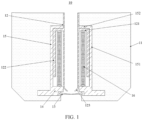
- an embodiment in a first aspect of this application provides an injection nozzle 10, including a body 11, an injection pipe 12, and a baffle 13.
- the body 11 contains a channel arranged along a height direction of the injection nozzle 10.
- a first outlet is disposed at a lower part of the channel.
- the injection pipe 12 is threaded through the channel in a manner of reciprocating movement along the height direction.
- the baffle 13 is connected to the body 11 and configured to cover the first outlet when a lower end portion of the injection pipe 12 is higher than the first outlet, and be propped open by the injection pipe 12 when the lower end portion of the injection pipe 12 is lower than the first outlet.
- the injection nozzle 10 is an apparatus that fits an injection port 500 of a chamber to be filled and that is configured to convey a liquid-to-be-injected to the injection port 500.
- the chamber to be filled may be a cavity formed by the housing of the battery cell.
- the liquid-to-be-injected is an electrolyte solution suitable for the battery cell.
- main solvents of the electrolyte solution include ethylene carbonate, dimethyl carbonate, ethyl methyl carbonate, diethyl carbonate, and the like.
- the main solvents of the electrolyte solution include propylene carbonate, ethylene glycol dimethyl ether, and the like.
- the injection port 500 may be understood as an opening created on the housing of the battery cell and configured to inject the liquid-to-be-injected into the chamber to be filled.
- the body 11 may be understood as a casing with a hollow space formed in the injection nozzle 10, and is configured to accommodate or connect and mount other components in the injection nozzle 10.
- the channel may be understood as a part of the hollow space formed by the body 11, where the part runs through the body 11 until both ends along the height direction of the body.
- the first outlet may be understood as an opening located at the lower portion of the channel and leading to the outside of the body 11.
- the structural shape and dimensions of the first outlet may be the same as or different from the structural shape and dimensions of the channel, and are not particularly limited in this application, as long as at least the dimensions of the first outlet are greater than or equal to the dimensions of the channel to facilitate the injection pipe 12 threaded through the channel to pass through the first outlet smoothly.
- the injection pipe 12 may be understood as a hollow cylindrical structure, and the two ends of the injection pipe extending along the height direction of the injection nozzle 10 communicate to each other.
- the liquid-to-be-inj ected can be conveyed from the upper end portion to the lower end portion of the injection pipe by the injection pipe 12.
- the injection pipe 12 of the injection nozzle can reciprocate in a channel in the body 11 of the injection nozzle along the height direction of the injection nozzle 10.
- a first outlet is disposed at the lower portion of the channel, and the baffle 13 is connected to the body 11 and configured to cover the first outlet when the lower end portion of the injection pipe 12 is higher than the first outlet and be propped open by the injection pipe 12 when the lower end portion of the injection pipe 12 is lower than the first outlet.
- the first outlet of the injection nozzle 10 is aligned with an injection port 500 of the chamber to be filled, and the injection pipe 12 is moved to prop the baffle 13 open, so that the lower end portion of the injection pipe 12 passes from the first outlet out of the body 11, that is, extends to the injection port 500 of the chamber to be filled.
- the liquid-to-be-injected is conveyed from the upper end portion of the injection pipe 12 to the lower end portion of the injection pipe 12, so as to enter the chamber to be filled and implement the injection of the liquid.
- the injection pipe 12 is moved back so that the lower end portion is restored to the position above the first outlet.
- the baffle 13 covers the first outlet to block the residual liquid dripping from the lower end portion of the injection pipe 12, thereby reducing the impact of the residual liquid on the external environment and other objects and reducing pollution.
- the liquid-to-be-injected is prevented from adhering to the inner wall of the body 11.
- the injection nozzle 10 further includes a spring 16.
- the spring 16 is disposed between the injection pipe 12 and the body 11 along an axial direction of the injection pipe 12 and is configured to elastically deform when the injection pipe 12 moves downward relative to the body 11.
- the spring 16 is a component made of an elastic material (such as spring steel), and deforms elastically when subjected to an external force and returns to the original state due to inherent elasticity when the external force is removed.
- an elastic material such as spring steel
- the spring 16 By disposing the spring 16 between the injection pipe 12 and the body 11 along the axial direction of the injection pipe 12, when a liquid needs to be injected, a force is applied to the injection pipe 12, so that the injection pipe 12 overcomes the elastic force of the spring 16 and moves downward to prop the baffle 13 open. At this time, the lower end portion of the injection pipe 12 extends from the first outlet to the injection port 500 of the chamber-to-be-filled to implement the injection. After completion of the injection, the force applied to the injection pipe 12 is canceled, so that the spring 16 is restored to the original state due to elasticity. At the same time, the spring drives the injection pipe 12 to move upward to automatically restore the injection pipe 12 to the original position. In this way, the operation of the injection process is simpler. The quick restoration of the injection pipe 12 to the original position can more effectively reduce the risk that the residual liquid accumulated at the lower end portion of the injection pipe 12 drips down onto other objects.
- the injection nozzle 10 further includes a first extension portion 121 connected to the injection pipe 12.
- the first extension portion 121 extends outward to the wall of the injection pipe 12 along the diameter direction of the injection pipe 12.
- the first extension portion 121 is connected to one end of the spring 16.
- the first extension portion 121 may be understood as a structure disposed outside the wall of the injection pipe 12 by being perpendicular to the axis of the injection pipe 12.
- the first extension portion 121 is of some hardness and strength.
- the first extension portion may be a plate structure made of a metal material, so as to provide, during the downward movement of the injection pipe 12, a reaction force to overcome the work done by the elastic force of the spring 16.
- the first extension portion 121 which extends outward to the wall of the injection pipe 12 along the diameter direction of the injection pipe 12, is connected to one end of the spring 16, and the first extension portion 121 is perpendicular to the axis of the injection pipe 12. In this way, it is more convenient to mount the spring 16 and position the spring 16 between the injection pipe 12 and the body 11 along the axial direction of the injection pipe 12. In addition, during the downward movement of the injection pipe 12 relative to the body 11, the first extension portion 121 is able to exert a pressure or tension on the spring 16 connected to the first extension portion, so as to deform the spring 16 elastically.
- the injection nozzle 10 further includes a fixed base 14 disposed opposite to the first extension portion 121.
- the fixed base 14 is fixed to the body 11 and connected to another end of the spring 16.
- the fixed base 14, located in a fixed position may be understood as a component playing a connection role for two or more components and a supporting role for some components.
- the fixed base 14 By disposing the fixed base 14 opposite to the first extension portion 121, the other end of the spring 16 is connected to the fixed base 14. Because the fixed base 14 is fixed to the body 11 and immovable, when a force is applied to the injection pipe 12 to move the injection pipe 12 downward, the first extension portion 121 drives an end of the spring 16 connected to the first extension portion 121 to move toward (or away from) the fixed base 14, so as to compress (or stretch) the spring 16 to deform the spring 16 elastically. For example, if the fixed base 14 is disposed on the lower side that is directly opposite to the first extension portion 121, the first extension portion 121 exerts a pressure on the spring 16 when the injection pipe 12 moves downward, so that the spring 16 is compressed between the first extension portion 121 and the fixed base 14.
- the original position may be understood as a position of the injection pipe 12 when the spring 16 is in its original state (without deforming elastically) or is not driven by an external force.
- the injection nozzle 10 further includes a second extension portion 122.
- One end of the second extension portion 122 is connected to the first extension portion 121.
- Another end of the second extension portion 122 is configured to contact the fixed base 14 after the injection pipe 12 moves downward for a preset distance.
- the preset distance is a preset maximum stroke within which the injection pipe 12 is movable.
- the maximum distance between the other end of the second extension portion 122 and the fixed base 14 along the axial direction of the injection pipe 12 is equal to the preset distance.
- the second extension portion 122 may be understood as a structure that extends downward from an end of the first extension portion 121 along the axis of the injection pipe 12, the end being away from the wall of the injection pipe 12.
- the fixed base 14 is positioned below the first extension portion 121, and the length of the second extension portion 122 is set according to the preset distance and the position of the fixed base 14.
- the second extension portion 122 and the first extension portion 121 may be formed in one piece by the same material, and the first extension portion 121 and the injection pipe 12 may be formed in one piece.
- the second extension portion 122 can fix the distance of downward movement of the injection pipe 12.
- the position of the lower end portion of the injection pipe extending to the injection port 500 is fixed as soon as the other end of the second extension portion 122 contacts the fixed base 14, that is, as soon as the lower end portion of the injection pipe 12 props the baffle 13 open, thereby preventing an excessive length by which the injection pipe 12 extends to the injection port 500.
- the excessive length of extension causes the wall of the injection pipe 12 to contact the liquid-to-be-injected or contact the injection port 500.
- the injection nozzle 10 further includes a limiting cylinder 15.
- the limiting cylinder 15 is disposed in the body 11 and configured to contact the wall of the injection pipe 12 and/or a sidewall of the second extension portion 122.
- the limiting cylinder 15 may be understood as a cylindrical structure configured to control a component to keep moving rectilinearly in a correct direction and formed around the correct direction.
- the limiting cylinder 15 may include a first limiting portion 151 disposed around the axis of the injection pipe 12, and a second limiting portion 152 disposed perpendicular to the first limiting portion 151.
- the sidewall of the first limiting portion 151 may contact the sidewall of the second extension portion.
- the second limiting portion 152 is designed to contact the wall of the injection pipe 12.
- the first limiting portion 151 and the second limiting portion 152 can simultaneously restrict the injection pipe 12 from wobbling radially.
- the steadiness of the reciprocating movement of the injection pipe 12 along the height direction of the injection nozzle 10 is improved, thereby preventing the lower end portion of the injection pipe 12 from scratching the sidewall of the injection port 500 due to wobbling after extending to the injection port 500.
- the limiting cylinder 15 is further configured to contact the first extension portion 121.
- an end of the first limiting portion 151, away from the second limiting portion 152, may be connected to the fixed base 14.
- the length of the first limiting portion 151 is determined based on the position of the fixed base 14 and the position at which the first extension portion 121 is located when the injection pipe 12 is not driven by an external force.
- the second limiting portion 152 is positioned above the position at which the first extension portion 121 is located when the injection pipe 12 is not driven by an external force, and is just in contact with the first extension portion 121.
- the spring 16 is compressed between the first extension portion 121 and the fixed base 14, after the external force applied to the injection pipe 12 is removed, one end of the spring 16 props the first extension portion 121 to rebound upward. Because the position of the second limiting portion 152 is fixed, the first extension portion 121 stops moving upon contacting the second limiting portion 152 during the upward movement. At this time, the injection pipe 12 is restored to the original position.
- the injection pipe 12 can be automatically restored to and reside in the original position more smoothly after the external force applied to the injection pipe 12 is removed.
- the baffle 13 is detachably connected between the body 11 and the fixed base 14.
- the baffle 13 is configured to block the residual liquid that drips from the lower end portion of the injection pipe 12, the residual liquid often contacts and adheres to the surface of the baffle. Especially, with a corrosive liquid, the baffle 13 is prone to be damaged. Therefore, by connecting the baffle 13 detachably between the body 11 and the fixed base 14, it is more convenient to clean and maintain the baffle 13 and replace the baffle 13.
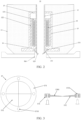
- the baffle 13 includes a fixing ring 131 and a plurality of sectorial elastic sheets 132.
- a plurality of first through-holes 1311 are created on the fixing ring. Curved edges of the plurality of sectorial elastic sheets 132 are embedded in the fixing ring 131 and connected to the fixing ring 131 by a bolt threaded through the first through-hole 1311. The bolt is also threaded through the body 11 and the fixed base 14.
- the fixing ring 131 is a ring-shaped component configured to fix the position of the baffle 13.
- the fixing ring may be made of metal, and therefore, the fixing ring can be easily fixed and connected to other components without deforming easily, be of specified hardness and strength, and can keep its own position and status unchanged after being fixed and mounted.
- a ring shape in geometry typically means a circular ring, and may be understood as a solid part that remains after a small concentric disc is removed from a large disc.
- the ring shape is of relatively high symmetry, and is a centrosymmetric figure that is symmetric around a center, and is also an axisymmetric figure that is symmetric around an infinite number of symmetry axes.
- the sectorial elastic sheet 132 may be understood as a sectorial sheet structure capable of deforming elastically and automatically restoring to an original state.
- the sector means a figure defined by two radii of a central angle and an arc opposite to the central angle.
- the axis of the injection pipe 12 is caused to align with the center of the fixing ring 131.
- the curved edges of the plurality of sectorial elastic sheets 132 are embedded in the fixing ring 131 to fill an inner circle of the fixing ring 131 and cover the first outlet. In this way, when the injection pipe 12 moves downward and contacts the sectorial elastic sheets 132, the tip portions of the sectorial elastic sheets 132 are prone to be propped open. At the same time, the plurality of sectorial elastic sheets 132 may be propped open simultaneously, and the structure in use is more stable.
- the first through-hole 1311 may be understood as a hole that completely runs through a solid portion of the fixing ring 131.
- the bolt is a mechanical fastener, and typically includes a head and a rod (a cylinder with external threads).
- Bolting is a connection manner of detachably fastening two or more components.
- a through-hole is generally created on at least one of the components, and a hole with internal threads fitting the external threads of the bolt is created on at least one of the components.
- all the components are fastened together by rotating the bolt by use of the fit between the bolt rod and the through-hole as well as the fit between the external threads and the internal threads.
- the bolt rod is screwed out of the through-hole to disassemble each connected component, thereby facilitating the disassembling and assembling operations.
- the bolt is threaded through the body 11, the fixing ring 131, the sectorial elastic sheet 132, and the fixed base 14 at the same time, so as to implement the connection between the sectorial elastic sheet 132 and the fixing ring 131 and detachably connect the baffle 13 between the body 11 and the fixed base 14.
- the fixing ring 131 and the plurality of sectorial elastic sheets 132 By disposing the fixing ring 131 and the plurality of sectorial elastic sheets 132, it is more convenient to fix the baffle 13 to a position of the body 11 at which the first outlet can be covered.
- the sectorial elastic sheets 132 of the baffle 13 can be automatically restored to the original state when the lower end portion of the injection pipe 12 moves upward to a position higher than the first outlet. In this way, upon completion of the injection, the injection pipe 12 is restored to the original position, and the baffle 13 is restored to the state of covering the first outlet to block the residual liquid that drips down from the injection pipe 12.
- a diversion portion 123 is disposed on the injection pipe 12.
- a diameter of the diversion portion 123 decreases gradually along a direction from an upper end portion of the injection pipe 12 to the lower end portion of the injection pipe 12.
- the diversion portion 123 may be understood as a portion configured to divert the liquid-to-be-injected in the injection pipe 12. As shown in FIG. 1 and FIG. 2 , the diversion portion 123 may be disposed at the lower end portion of the injection pipe 12.
- the liquid-to-be-injected in the injection pipe 12 can centrally converge into a thin-diameter liquid column to enter the injection port 500 after flowing top-down to the diversion portion 123, so as to more effectively prevent the liquid-to-be-injected from splashing down onto other components and objects.
- the baffle 13 includes a beveled face 1301 that fits the diversion portion 123.
- the beveled face 1301 may be understood as a flat face at an inclination to a plane on the baffle 13, where the inclination is typically an acute angle.
- the beveled face 1301 may be an upper surface of the sectorial elastic sheet 132, the upper surface being inclined at an angle to the lower surface of the sectorial elastic sheet.
- the injection pipe 12 can contact and fit the baffle 13 and prop the baffle 13 open more easily when the injection pipe 12 moves downward.
- the injection nozzle 10 includes a body 11, an injection pipe 12, a baffle 13, a fixed base 14, a limiting cylinder 15, and a spring 16.
- the body 11 includes a channel arranged along the height direction of the injection nozzle 10. A first outlet is created at the lower portion of the channel.
- the injection pipe 12 is threaded through the channel in a manner of reciprocating along the height direction.
- the injection pipe 12 includes a first extension portion 121 and a second extension portion 122.
- the first extension portion 121 is connected to one end of the spring 16.
- the fixed base is disposed opposite to the first extension portion 121.
- the fixed base 14 is fixed to the body 11 and connected to the other end of the spring 16.
- the other end of the second extension portion 122 is configured to contact the fixed base 14 after the injection pipe 12 moves downward for a preset distance.
- the spring 16 is configured to deform elastically when the injection pipe 12 moves downward relative to the body 11.
- the spring 16 is configured to deform elastically when the injection pipe 12 moves downward relative to the body 11.
- the limiting cylinder 15 is connected to the fixed base 14 and configured to contact the wall of the injection pipe 12, the upper surface of the first extension portion 121, and the sidewall of the second extension portion 122.
- the baffle 13 is detachably connected between the body 11 and the fixed base 14, and includes a fixing ring 131 and a plurality of sectorial elastic sheets 132.
- the curved edges of the plurality of sectorial elastic sheets 132 are embedded in the fixing ring 131, and connected to the fixing ring 131 by the bolt threaded through the first through-hole 1311.
- the bolt also runs through the body 11 and the fixed base 14.
- the plurality of sectorial elastic sheets 132 cover the first outlet when the lower end portion of the injection pipe 12 is higher than the first outlet, and are propped open by the injection pipe 12 when the lower end portion of the injection pipe 12 is lower than the first outlet.
- the injection pipe 12 of the injection nozzle can reciprocate in a channel in the body 11 of the injection nozzle along the height direction of the injection nozzle 10.
- a first outlet is disposed at the lower portion of the channel, and a plurality of sectorial elastic sheets 132 of the baffle 13 cover the first outlet when the lower end portion of the injection pipe 12 is higher than the first outlet and are propped open by the injection pipe 12 when the lower end portion of the injection pipe 12 is lower than the first outlet.
- the first outlet of the injection nozzle 10 is aligned with an injection port 500 of the chamber to be filled, and the injection pipe 12 is moved to prop open the plurality of sectorial elastic sheets 132 of the baffle 13, so that the lower end portion of the injection pipe 12 passes from the first outlet out of the body 11, that is, extends to the injection port 500 of the chamber to be filled.
- the liquid-to-be-injected is conveyed from the upper end portion of the injection pipe 12 to the lower end portion of the injection pipe 12, so as to enter the chamber to be filled and implement the injection of the liquid.
- the spring 16 After completion of the injection, the spring 16 is restored to the original state due to elasticity, and drives the injection pipe 12 to move upward to automatically restore the injection pipe 12 to the original position, so that the lower end portion of the injection pipe 12 is restored to the position above the first outlet.
- the plurality of sectorial elastic sheets 132 are restored to the original state and cover the first outlet to block the residual liquid dripping from the lower end portion of the injection pipe 12, thereby reducing the impact of the residual liquid on the external environment and other objects and reducing pollution.
- the liquid-to-be-injected is prevented from adhering to the inner wall of the body 11.
- the injection pipe 12 can be automatically restored to and reside in the original position more smoothly after the external force applied to the injection pipe 12 is removed.
- the second extension portion 122 can also fix the distance of downward movement of the injection pipe 12.
- the position of the lower end portion of the injection pipe extending to the injection port 500 is fixed as soon as the other end of the second extension portion 122 contacts the fixed base 14, that is, as soon as the lower end portion of the injection pipe 12 props the baffle 13 open, thereby preventing an excessive length by which the injection pipe 12 extends to the injection port 500.
- the excessive length of extension causes the wall of the injection pipe 12 to contact the liquid-to-be-injected or contact the injection port 500.
- an embodiment in a second aspect of this application provides an injection apparatus.
- the injection apparatus includes the injection nozzle 10 according to an embodiment in the first aspect of this application.
- the injection pipe 12 of the injection nozzle 10 in the injection apparatus can reciprocate in a channel in the body 11 of the injection nozzle along the height direction of the injection nozzle 10.
- a first outlet is disposed at the lower portion of the channel, and the baffle 13 is connected to the body 11 and configured to cover the first outlet when the lower end portion of the injection pipe 12 is higher than the first outlet and be propped open by the injection pipe 12 when the lower end portion of the injection pipe 12 is lower than the first outlet.
- the first outlet of the injection nozzle 10 is aligned with an injection port 500 of the chamber to be filled, and the injection pipe 12 is driven to prop the baffle 13 open, so that the lower end portion of the injection pipe 12 passes from the first outlet out of the body 11, that is, extends to the injection port 500 of the chamber to be filled.
- the liquid-to-be-injected is conveyed from the upper end portion of the injection pipe 12 to the lower end portion of the injection pipe 12, so as to enter the chamber to be filled and implement the injection of the liquid.
- the injection pipe 12 is moved back so that the lower end portion is restored to the position above the first outlet.
- the baffle 13 covers the first outlet to block the residual liquid dripping from the lower end portion of the injection pipe 12, thereby reducing the impact of the residual liquid on the external environment and other objects and reducing pollution.
- the liquid-to-be-injected is prevented from adhering to the inner wall of the body 11.
- the injection apparatus further includes an injection cup 20, a driving mechanism, and a stopper rod 30.
- the injection cup 20 includes a chamber 21 configured to accommodate an electrolyte solution, an upper cover 22 disposed at one end of the chamber 21, and a lower cover 23 disposed at another end of the chamber 21.
- a second through-hole is created on the lower cover 23.
- the injection pipe 12 of the injection nozzle 10 is fixedly threaded through the second through-hole and communicates with the chamber 21.
- a third through-hole is created on the upper cover 22.
- the driving mechanism is configured to drive the injection cup 20 to move from a first position to a second position.
- the stopper rod 30 is fixed in a position and threaded through the third through-hole.
- One end of the stopper rod 30 is configured to be in close contact with an upper end portion of the injection pipe 12 and, when the injection cup 20 reaches the second position, be disengaged from the injection pipe 12.
- the injection cup 20 may be understood as a container configured to store the liquid-to-be-injected and, during an injection operation, provide the liquid-to-be-injected to the injection pipe 12.
- the chamber 21 may be understood as a hollowed-out structure configured to isolate the liquid-to-be-injected from the outside.
- the upper cover 22 may be understood as a structure that fits the top of the chamber 21 in the height direction of the injection apparatus and that is configured to cover the top of the chamber 21 and be connected to other components.
- the lower cover 23 may be understood as a structure that fits the bottom of the chamber 21 in the height direction of the injection apparatus and that is configured to cover the bottom of the chamber 21 and be connected to other components.
- the second through-hole may be understood as a hole that completely runs through the lower cover 23 along the height direction of the injection apparatus.
- the third through-hole may be understood as a hole that completely runs through the upper cover 22 along the height direction of the injection apparatus.
- the driving mechanism may be understood as an apparatus capable of providing a power source and transmitting the power, so as to drive other movable components or machines to move in a desired manner of movement.
- the driving mechanism may be understood as an apparatus that drives the injection cup 20 to move downward along the height direction of the injection apparatus.
- the first position may be understood as a position of the injection cup 20 in the height direction without being driven by the driving mechanism.
- the second position may be understood as a position of the injection cup 20 in the height direction when the lower end portion of the injection pipe 12 is in a desired position after propping the baffle 13 open.
- the position in the height direction means a spatial point along the height direction of the injection apparatus.
- the desired position means a position at which the lowest point of the lower end portion of the injection pipe 12 resides when the liquid-to-be-injected flowing out can just enter the injection port 500 after the injection pipe 12 moves downward and props the baffle 13 open.
- the lowest point of the lower end portion of the injection pipe 12 is flush with the upper surface of the injection port 500 after the injection pipe 12 moves downward and props the baffle 13 open.
- the lower end portion of the injection pipe 12 is excessively high over the injection port 500 and thereby makes the liquid-to-be-injected prone to be splashed onto the outside of the injection port 500 or other objects, and in turn, results in waste and pollution.
- the injection pipe 12 extends to the injection port 500 for an excessive length that causes the wall of the injection pipe 12 to contact the liquid-to-be-injected or contact the injection port 500.
- the stopper rod 30 may be understood as an elongated structure extending along the height direction of the injection apparatus.
- the stopper rod 30 By disposing the injection cup 20, the driving mechanism, and the stopper rod 30, when the driving mechanism is not driving the injection cup 20, the stopper rod 30 is in close contact with the upper end portion of the injection pipe 12, so that the liquid-to-be-injected in the chamber 21 of the injection cup 20 is unable to flow into the injection pipe 12.
- the driving mechanism drives the injection cup 20 until the injection cup 20 reaches the second position, the injection cup 20 accordingly drives the injection pipe 12 to move downward until the lower end portion reaches a desired position, where the injection pipe is fixedly threaded through the lower cover 23 of the injection cup.
- the stopper rod 30 is disengaged from the injection pipe 12, the injection pipe 12 communicates with the chamber 21, and the liquid-to-be-injected flows downward from the upper end portion to the lower end portion of the injection pipe 12 to enter the injection port 500, thereby implementing the liquid injection.
Landscapes
- Chemical & Material Sciences (AREA)
- Chemical Kinetics & Catalysis (AREA)
- Electrochemistry (AREA)
- General Chemical & Material Sciences (AREA)
- Nozzles (AREA)
- Filling, Topping-Up Batteries (AREA)
Applications Claiming Priority (2)
| Application Number | Priority Date | Filing Date | Title |
|---|---|---|---|
| CN202210002258.XA CN116435724B (zh) | 2022-01-04 | 2022-01-04 | 注液嘴及具有其的注液装置 |
| PCT/CN2022/142776 WO2023131024A1 (zh) | 2022-01-04 | 2022-12-28 | 注液嘴及具有其的注液装置 |
Publications (2)
| Publication Number | Publication Date |
|---|---|
| EP4372902A1 true EP4372902A1 (de) | 2024-05-22 |
| EP4372902A4 EP4372902A4 (de) | 2024-12-25 |
Family
ID=87073148
Family Applications (1)
| Application Number | Title | Priority Date | Filing Date |
|---|---|---|---|
| EP22918465.0A Pending EP4372902A4 (de) | 2022-01-04 | 2022-12-28 | Flüssigkeitseinspritzdüse und flüssigkeitseinspritzvorrichtung damit |
Country Status (4)
| Country | Link |
|---|---|
| US (1) | US12444816B2 (de) |
| EP (1) | EP4372902A4 (de) |
| CN (1) | CN116435724B (de) |
| WO (1) | WO2023131024A1 (de) |
Families Citing this family (2)
| Publication number | Priority date | Publication date | Assignee | Title |
|---|---|---|---|---|
| CN117720056B (zh) * | 2024-02-05 | 2024-05-10 | 黄山桃源食品有限公司 | 罐头注液机 |
| CN119098296B (zh) * | 2024-09-06 | 2025-10-10 | 杭州宏华数码科技股份有限公司 | 用于目标对象喷涂的喷头 |
Family Cites Families (19)
| Publication number | Priority date | Publication date | Assignee | Title |
|---|---|---|---|---|
| US4492253A (en) * | 1980-12-29 | 1985-01-08 | Red Valve Company, Inc. | Tide gate valve |
| JP2003288890A (ja) * | 2002-03-27 | 2003-10-10 | Japan Storage Battery Co Ltd | 蓄電池 |
| JP2005190689A (ja) * | 2003-12-24 | 2005-07-14 | Sanyo Electric Co Ltd | 密閉型電池 |
| US7445028B1 (en) * | 2005-09-26 | 2008-11-04 | General Rubber Corporation | Check valves |
| CN203218393U (zh) | 2013-04-12 | 2013-09-25 | 东莞新能源科技有限公司 | 可防止滴液的注液嘴 |
| CN106241700A (zh) * | 2016-08-29 | 2016-12-21 | 成都灵感元素科技有限公司 | 一种带防滴漏装置的罐装机 |
| CN106601978B (zh) | 2016-12-16 | 2019-02-22 | 宁德时代新能源科技股份有限公司 | 注液装置 |
| CN206301868U (zh) | 2016-12-29 | 2017-07-04 | 宁德时代新能源科技股份有限公司 | 注液装置及电池 |
| CN206490131U (zh) * | 2016-12-30 | 2017-09-12 | 深圳市新嘉拓自动化技术有限公司 | 注液机的注液嘴 |
| CN206742375U (zh) * | 2017-02-08 | 2017-12-12 | 宁德时代新能源科技股份有限公司 | 注液头、硬壳电池的注液系统以及硬壳电池的排气系统 |
| CN107394106A (zh) * | 2017-07-26 | 2017-11-24 | 力信(江苏)能源科技有限责任公司 | 一种锂离子动力电池注液装置 |
| CN207303224U (zh) * | 2017-09-12 | 2018-05-01 | 杭州百银新能源科技有限公司 | 一种柔性注液嘴 |
| CN108011072B (zh) * | 2018-01-04 | 2024-09-06 | 宁德嘉拓智能设备有限公司 | 一种注液装置 |
| CN208028145U (zh) | 2018-03-09 | 2018-10-30 | 合肥恒宇新能源有限公司 | 一种防滴液的锂离子电池注液嘴 |
| CN109390503A (zh) * | 2018-11-15 | 2019-02-26 | 河北银隆新能源有限公司 | 一种电池注液嘴结构及电池 |
| CN209200060U (zh) * | 2018-11-22 | 2019-08-02 | 河北银隆新能源有限公司 | 一种注液机的注液嘴结构及注液机 |
| CN210113656U (zh) * | 2019-07-30 | 2020-02-25 | 惠州卓尔丰科技有限公司 | 一种锂电池注液设备 |
| CN110600670A (zh) * | 2019-10-30 | 2019-12-20 | 东莞市德瑞精密设备有限公司 | 一种注液杯及其注液方式 |
| CN110803672A (zh) * | 2019-11-06 | 2020-02-18 | 安徽省含山县华康调味品厂 | 一种用于生产调味油的易清洁灌装机 |
-
2022
- 2022-01-04 CN CN202210002258.XA patent/CN116435724B/zh active Active
- 2022-12-28 WO PCT/CN2022/142776 patent/WO2023131024A1/zh not_active Ceased
- 2022-12-28 EP EP22918465.0A patent/EP4372902A4/de active Pending
-
2024
- 2024-05-17 US US18/666,815 patent/US12444816B2/en active Active
Also Published As
| Publication number | Publication date |
|---|---|
| US12444816B2 (en) | 2025-10-14 |
| WO2023131024A1 (zh) | 2023-07-13 |
| CN116435724A (zh) | 2023-07-14 |
| EP4372902A4 (de) | 2024-12-25 |
| US20240304964A1 (en) | 2024-09-12 |
| CN116435724B (zh) | 2025-10-03 |
Similar Documents
| Publication | Publication Date | Title |
|---|---|---|
| US12444816B2 (en) | Injection nozzle and injection apparatus containing same | |
| US20230125313A1 (en) | End cap assembly, battery cell, battery, and electrical device | |
| EP3934012B1 (de) | Endabdeckungsanordnung, sekundärbatterie, batteriepack und vorrichtung mit batterie | |
| EP3048657B1 (de) | Schweissloses batteriepack mit eindrückniet | |
| EP4310970A1 (de) | Verfahren zur verarbeitung einer lithium-ionen-batterie | |
| EP4273994A1 (de) | Vorrichtung zur montage einer zelle in einem gehäuse, batteriezellenmontagevorrichtung und zellenmontageverfahren | |
| KR102871896B1 (ko) | 배터리 보관 장치 및 오일링 방법 | |
| US12583063B2 (en) | Press plate module, production line, and control method | |
| EP4620872A1 (de) | Flüssigkeitseinspritzsystem für batterie und übertragungsvorrichtung dafür | |
| CN214043925U (zh) | 一种锂离子电池极耳保护装置 | |
| EP4290632A1 (de) | Montagevorrichtung für batteriezelle | |
| CN214641353U (zh) | 一种锂电池焊接夹具 | |
| EP4601089A1 (de) | Batteriezellenanordnung, batteriepack und transportvorrichtung damit | |
| CN110828720A (zh) | 一种电池盖板 | |
| EP4691683A1 (de) | Schweisshalterung und schweissvorrichtung damit | |
| EP4383413A1 (de) | Schweissklemme | |
| US20180269699A1 (en) | Apparatus for charging and discharging battery cell comprising insulation mask | |
| US20240424522A1 (en) | Feeding apparatus, gluing device, and control method of feeding apparatus | |
| CN218677517U (zh) | 液体输出机构及清洁设备 | |
| EP3654432A1 (de) | Stapelvorrichtung für flexible verpackungsbatterie | |
| CN222695731U (zh) | 冲压设备及生产系统 | |
| CN221080175U (zh) | 顶盖组件以及电池包 | |
| CN220679936U (zh) | 组装装置 | |
| KR102962066B1 (ko) | 전지셀 어셈블리, 배터리팩 및 그것을 포함한 이동수단 | |
| CN220106622U (zh) | 一种定位装置 |
Legal Events
| Date | Code | Title | Description |
|---|---|---|---|
| STAA | Information on the status of an ep patent application or granted ep patent |
Free format text: STATUS: THE INTERNATIONAL PUBLICATION HAS BEEN MADE |
|
| PUAI | Public reference made under article 153(3) epc to a published international application that has entered the european phase |
Free format text: ORIGINAL CODE: 0009012 |
|
| STAA | Information on the status of an ep patent application or granted ep patent |
Free format text: STATUS: REQUEST FOR EXAMINATION WAS MADE |
|
| 17P | Request for examination filed |
Effective date: 20240212 |
|
| AK | Designated contracting states |
Kind code of ref document: A1 Designated state(s): AL AT BE BG CH CY CZ DE DK EE ES FI FR GB GR HR HU IE IS IT LI LT LU LV MC ME MK MT NL NO PL PT RO RS SE SI SK SM TR |
|
| RAP1 | Party data changed (applicant data changed or rights of an application transferred) |
Owner name: CONTEMPORARY AMPEREX TECHNOLOGY(HONG KONG) LIMITED |
|
| A4 | Supplementary search report drawn up and despatched |
Effective date: 20241125 |
|
| RIC1 | Information provided on ipc code assigned before grant |
Ipc: B05B 1/32 20060101ALI20241119BHEP Ipc: H01M 50/627 20210101ALI20241119BHEP Ipc: H01M 50/673 20210101ALI20241119BHEP Ipc: H01M 50/655 20210101ALI20241119BHEP Ipc: H01M 50/636 20210101ALI20241119BHEP Ipc: H01M 50/618 20210101ALI20241119BHEP Ipc: H01M 50/609 20210101ALI20241119BHEP Ipc: H01M 50/60 20210101AFI20241119BHEP |
|
| DAV | Request for validation of the european patent (deleted) | ||
| DAX | Request for extension of the european patent (deleted) |