EP4366995B1 - Appareil comprenant un dispositif de freinage magnéto-rhéologique et procédé - Google Patents
Appareil comprenant un dispositif de freinage magnéto-rhéologique et procédé Download PDFInfo
- Publication number
- EP4366995B1 EP4366995B1 EP22744442.9A EP22744442A EP4366995B1 EP 4366995 B1 EP4366995 B1 EP 4366995B1 EP 22744442 A EP22744442 A EP 22744442A EP 4366995 B1 EP4366995 B1 EP 4366995B1
- Authority
- EP
- European Patent Office
- Prior art keywords
- particles
- gap
- braking
- magnetically polarizable
- magnetic field
- Prior art date
- Legal status (The legal status is an assumption and is not a legal conclusion. Google has not performed a legal analysis and makes no representation as to the accuracy of the status listed.)
- Active
Links
Images


Classifications
-
- F—MECHANICAL ENGINEERING; LIGHTING; HEATING; WEAPONS; BLASTING
- F16—ENGINEERING ELEMENTS AND UNITS; GENERAL MEASURES FOR PRODUCING AND MAINTAINING EFFECTIVE FUNCTIONING OF MACHINES OR INSTALLATIONS; THERMAL INSULATION IN GENERAL
- F16D—COUPLINGS FOR TRANSMITTING ROTATION; CLUTCHES; BRAKES
- F16D63/00—Brakes not otherwise provided for; Brakes combining more than one of the types of groups F16D49/00 - F16D61/00
- F16D63/002—Brakes with direct electrical or electro-magnetic actuation
-
- F—MECHANICAL ENGINEERING; LIGHTING; HEATING; WEAPONS; BLASTING
- F16—ENGINEERING ELEMENTS AND UNITS; GENERAL MEASURES FOR PRODUCING AND MAINTAINING EFFECTIVE FUNCTIONING OF MACHINES OR INSTALLATIONS; THERMAL INSULATION IN GENERAL
- F16D—COUPLINGS FOR TRANSMITTING ROTATION; CLUTCHES; BRAKES
- F16D57/00—Liquid-resistance brakes; Brakes using the internal friction of fluids or fluid-like media, e.g. powders
- F16D57/002—Liquid-resistance brakes; Brakes using the internal friction of fluids or fluid-like media, e.g. powders comprising a medium with electrically or magnetically controlled internal friction, e.g. electrorheological fluid, magnetic powder
-
- B—PERFORMING OPERATIONS; TRANSPORTING
- B60—VEHICLES IN GENERAL
- B60T—VEHICLE BRAKE CONTROL SYSTEMS OR PARTS THEREOF; BRAKE CONTROL SYSTEMS OR PARTS THEREOF, IN GENERAL; ARRANGEMENT OF BRAKING ELEMENTS ON VEHICLES IN GENERAL; PORTABLE DEVICES FOR PREVENTING UNWANTED MOVEMENT OF VEHICLES; VEHICLE MODIFICATIONS TO FACILITATE COOLING OF BRAKES
- B60T13/00—Transmitting braking action from initiating means to ultimate brake actuator with power assistance or drive; Brake systems incorporating such transmitting means, e.g. air-pressure brake systems
- B60T13/74—Transmitting braking action from initiating means to ultimate brake actuator with power assistance or drive; Brake systems incorporating such transmitting means, e.g. air-pressure brake systems with electrical assistance or drive
- B60T13/748—Transmitting braking action from initiating means to ultimate brake actuator with power assistance or drive; Brake systems incorporating such transmitting means, e.g. air-pressure brake systems with electrical assistance or drive acting on electro-magnetic brakes
-
- F—MECHANICAL ENGINEERING; LIGHTING; HEATING; WEAPONS; BLASTING
- F16—ENGINEERING ELEMENTS AND UNITS; GENERAL MEASURES FOR PRODUCING AND MAINTAINING EFFECTIVE FUNCTIONING OF MACHINES OR INSTALLATIONS; THERMAL INSULATION IN GENERAL
- F16D—COUPLINGS FOR TRANSMITTING ROTATION; CLUTCHES; BRAKES
- F16D57/00—Liquid-resistance brakes; Brakes using the internal friction of fluids or fluid-like media, e.g. powders
- F16D57/02—Liquid-resistance brakes; Brakes using the internal friction of fluids or fluid-like media, e.g. powders with blades or like members braked by the fluid
-
- F—MECHANICAL ENGINEERING; LIGHTING; HEATING; WEAPONS; BLASTING
- F16—ENGINEERING ELEMENTS AND UNITS; GENERAL MEASURES FOR PRODUCING AND MAINTAINING EFFECTIVE FUNCTIONING OF MACHINES OR INSTALLATIONS; THERMAL INSULATION IN GENERAL
- F16D—COUPLINGS FOR TRANSMITTING ROTATION; CLUTCHES; BRAKES
- F16D2121/00—Type of actuator operation force
- F16D2121/18—Electric or magnetic
- F16D2121/28—Electric or magnetic using electrostrictive or magnetostrictive elements, e.g. piezoelectric elements
Definitions
- the present invention relates to a device with a magnetorheological braking device for braking relative movements and a corresponding method.
- a device according to the invention or the magnetorheological braking device comprises at least two braking components, between which at least one receiving space with at least one braking gap is formed.
- the braking gap is at least partially filled with a magnetorheological medium containing polarizable particles that can be influenced by a magnetic field.
- magnetorheological fluids A primary application of magnetorheological fluids is in shock absorbers, where the magnetorheological fluid flows from one chamber to another. High pressures and flow velocities can occur here.
- the magnetorheological fluid contains a large number of small, round particles to facilitate the flow from one chamber to the other. Low flow resistance is important to achieve low base damping.
- magnetorheological braking devices have become known in which the deceleration of the two brake components, which are movable relative to one another, is achieved by means of a shear stress between two, for example, plate-shaped surfaces.
- the magnetorheological fluid is located between the plates.
- the magnetic field flows through the magnetorheological fluid perpendicular to the direction of movement of the plate-shaped surfaces.
- This type of shear stress is used particularly in clutches and brakes. If a magnetic field is applied, A change in viscosity occurs very quickly, since only the magnetically polarizable particles need to be aligned. Thus, force changes can be realized within a few milliseconds.
- the shear stress behaves like a Newtonian fluid in a magnetic field-free space, and like a Bingham fluid in a magnetic field.
- the magnetic field polarizes the particles, forming chains along the field lines.
- the JP 2013 181 598 A deals with the problem that clumping can occur in magnetorheological fluids due to particle sedimentation. This can occur, for example, if a magnetorheological brake is not moved for a longer period of time. Furthermore, the JP 2013 181 598 A The problem is that the viscosity of the magnetorheological fluid can increase when rotating at high speeds or shear rates. As a solution, it is proposed that the magnetorheological fluid contain, in addition to the first particles (e.g., carbonyl iron particles), second nanosized particles. This mixture reduces the viscosity increase of the magnetorheological fluid at high speeds and simultaneously prevents sedimentation. Furthermore, both particle types are each coated with a surface modification layer. This improves the affinity for the dispersant (e.g., silicone oil).
- the dispersant e.g., silicone oil
- US 2003/071238A1 discloses a magnetorheological device with non-circular magnetorheological particles of different sizes. A friction-reducing additive is added.
- US 2002/110704 A discloses a magnetorheological fluid with non-circular magnetorheological particles.
- magnetorheological braking devices are required that are particularly compact and can provide a particularly high braking torque.
- a rotary brake with small diameters of, for example, 60 mm or smaller and a cylindrical braking gap, it is difficult to achieve a high field strength in the braking gap (effective gap). Because the central core or other parts of the magnetic circuit saturate first. A high coil current of the electrical coil therefore does not lead to any improvement if parts of the magnetic circuit are saturated.
- the smaller the diameter the sooner the core saturates, and the less favorable the magnetic circuit surfaces become relative to each other. This means that smaller actuators have even lower flux densities in the braking gap.
- the EP 2 616 704 B1 The applicant has become aware of a structure in which rotating parts, such as rollers, are arranged in the braking gap. These rollers specifically influence the course of the magnetic field acting on the magnetically polarizable particles (e.g., carbonyl iron particles) in the magnetorheological fluid. Due to the magnetic field's effect on the magnetically polarizable particles, a (geometric) wedge consisting of accumulated particles forms in front of the rotating round surfaces of the rollers or rotating bodies. The rollers can therefore also be referred to as magnetic field concentrators. This increases the braking torque.
- the magnetically polarizable particles e.g., carbonyl iron particles
- the rollers can therefore also be referred to as magnetic field concentrators. This increases the braking torque.
- the magnetically polarizable particles such as carbonyl iron particles
- the resulting increased particle concentration causes higher shear forces, which can generate higher braking torques.
- the radially inner brake component is formed by a star- or gear-like structure, so that the brake gap has a variable gap height over the circumference, for example, if the outer brake component is cylindrical on the inner circumference.
- the designs work according to the DE 10 2020 106 328 B3 or the EP 2 616 704 B1 satisfactory, whereby with the latter design, in which rotating bodies are used in the brake gap, even higher braking torques can be achieved than with the variant where, for example, a star contour in the brake gap ensures a variable gap height.
- a star contour in the brake gap ensures a variable gap height.
- a device comprises one or at least one magnetorheological braking device for braking relative movements.
- the braking device comprises at least two braking components, wherein a receiving space with at least one braking gap is formed between the braking components.
- the receiving space contains at least one magnetorheological medium with magnetically polarizable particles (magnetorheological particles) that can be influenced by a magnetic field.
- at least one core and at least one electrical coil unit are included to generate a controllable magnetic field. in the brake gap.
- At least some of the magnetically polarizable particles are designed to form a canting structure under the influence of the magnetic field and to clamp or wedge together. (This essentially forms a wedge at the particle level.)
- the ratio of maximum diameter to maximum transverse extent perpendicular to it is greater than 1.25, which are present as non-circular particles.
- the device according to the invention has many advantages.
- a significant advantage of the device according to the invention is that the magnetorheological particles of the magnetorheological medium are designed in such a way that they can form a canting structure with one another, which can be canted or jammed together, thereby forming a significantly stronger structure. This makes it possible to generate a considerably greater braking torque than was possible with the prior art.
- the magnetically acting forces are mechanically amplified by the canting structure.
- the magnetically polarizable particles are formed in particular by carbonyl iron particles.
- Liquids are available on the market with 40 percent by volume. (Custom) blends with between 40 and 50 percent by volume carbonyl iron are possible. More is not possible, as the carrier liquid takes up the remaining volume.
- the remaining design parameters are adapted accordingly (e.g. the field strength per particle should remain roughly the same as with MR fluid, i.e. the field strength in the braking gap or effective gap should be twice as high when changing from LORD MRF 140 (40 volume percent carbonyl iron with, for example, oil as a carrier fluid) to 80% carbonyl iron powder (without carrier fluid).
- LORD MRF 140 40 volume percent carbonyl iron with, for example, oil as a carrier fluid
- a further advantage of using powder as the medium in the active gap is that it eliminates sedimentation and clumping in the sense that "the iron particles in MR fluids are drawn in the direction of the magnetic field gradient (the force on magnetizable particles always acts in the direction of the stronger magnetic field, displacing the carrier medium)" to achieve such high particle concentrations.
- the maximum particle concentration is already present. This improves the reproducibility of the torques (a similar braking torque is always achieved at the same current).
- the magnetically polarizable particles comprise non-spherical particles, in which the ratio of the largest diameter to the largest transverse extent perpendicular thereto is greater than 1.5. It is also possible to form this ratio as a ratio of the largest longitudinal extent to the largest transverse extent, wherein in particular the longitudinal and Transverse extensions are measured perpendicular to each other.
- non-circular particles are particularly advantageous because they enable an effective canting structure, as different non-circular sections of the particles clamp or wedge together.
- ratios of the largest diameter to the largest transverse extent perpendicular thereto are also possible and preferred.
- the magnetically polarizable particles are designed to clamp or wedge together under the influence of the magnetic field. This is possible, for example, with particles that are partially angular or, for example, entirely triangular or polygonal, or the like. Two (or more) correspondingly designed particles then clamp together and can cause very effective clumping of the particles and the clamping and deceleration of the two braking components together.
- the magnetically polarizable particles are designed to clamp or wedge together at two or more spaced-apart locations under the influence of the magnetic field.
- Such non-circular particles allow for a very effective increase in the braking force or braking torque, since, unlike spherical particles, they do not only touch at one point or within a small angular range, but at multiple points or even across a large area.
- At least some of the magnetically polarizable particles have at least one trough section.
- Such an inwardly curved trough section allows particularly effective wedging with parts of other particles.
- At least one surface of at least one brake component adjacent to the brake gap is at least partially unsmooth or (locally) uneven. It is also possible for the particles or a significant portion of the magnetically polarizable particles to have regular or irregular elevations or ridges and/or depressions on the outer surface. This can increase jamming with the particles.
- at least one surface can have elevations and/or depressions similar to pointed or rounded dimples on golf balls. A surface with a pointed or rounded sawtooth profile is also possible.
- a relative height (of at least some of) the elevations or depressions is preferably at least 5% or 10% of the minimum diameter of a magnetically polarizable particle.
- At least some of the magnetically polarizable particles have at least one angled structural section. Angled structures allow for particularly effective clamping between them, thus generating a high braking torque.
- a projection or edge of one particle is clamped with a recess or trough portion of another particle.
- the tilting of the magnetically polarizable particles can occur not only two-dimensionally, but also three-dimensionally (e.g. also in the axial direction).
- a magnetic field strength of greater than 150 kiloamperes/meter (kA/m), 250 kiloamperes/meter, or 500 kA/m or more is preferably generated in the brake gap.
- a magnetic field strength of greater than 500 kiloamperes/meter (kA/m), 750 kiloamperes/meter, or 1000 kA/m or more can be generated in the brake gap or is generated there.
- the minimum gap height of the braking gap between the braking components is less than five times the largest diameter of the magnetically polarizable particles in the braking gap.
- a minimum gap height of the braking gap between the braking components is greater than twice the maximum transverse extent perpendicular to the maximum diameter of the magnetically polarizable particles in the braking gap.
- the minimum gap height of the braking gap between the braking components is greater than three times the maximum transverse extent perpendicular to the maximum diameter of the magnetically polarizable particles in the braking gap. This ensures a low basic torque or a low basic force, while at the same time a particularly high braking torque or a particularly high braking force can be generated.
- At least 10% and in particular at least 20% of the magnetically polarizable particles have a Ratio of maximum diameter to maximum transverse extent of greater than 1.5 or greater than 2.0.
- a ratio of maximum diameter to maximum transverse extent perpendicular thereto is greater than 1.25 or greater than 1.5 or greater than 2.0.
- At least 10%, 25%, 33%, or 50% of the magnetically polarizable particles have a maximum diameter and/or a maximum transverse extent of at least 10 ⁇ m. It has been found that a higher braking effect can be achieved with larger particles than with smaller particles. Therefore, it is preferred that at least 10%, 25%, 33%, or 50% of the magnetically polarizable particles have a maximum diameter of at least 20 ⁇ m, or at least 30 ⁇ m, or at least 50 ⁇ m. Smaller particles may be included.
- At least one load sensor such as a torque sensor or torque transducer or torque observer and/or a force sensor
- at least one position sensor for detecting an angular position and/or relative position is included.
- the coil unit may comprise a (cylindrical) coil wire.
- the coil wire may be made of a flat material. It is also possible to use a wire with a customized contour made of copper or another suitable material.
- the two brake components are pivotable relative to one another.
- the two brake components it is also possible for the two brake components to be movable linearly relative to one another.
- the two brake components are continuously rotatable relative to one another.
- the electrical coil unit or several coil units can be wound radially and/or axially around the core.
- the brake gap completely radially surrounds the inner component.
- the brake gap can, in particular, be designed as a circumferential annular gap.
- At least one brake component prefferably be provided with a star-shaped contour or the like that extends toward the other brake component, creating or providing a gap height that is variable over the circumference or length of the brake gap.
- Radially projecting arms or a star-shaped contour form local magnetic field concentrators that lead to a local increase in the field strength in the brake gap. This increases the jamming and clumping of individual non-circular particles.
- At least one rotating body is arranged in at least one gap section of the brake gap.
- a rotating body can, for example, be in the form of a ball or In particular, it can be designed as a roller and can also lead to the (geometric) wedge effect described in the prior art, which also leads to clumping or jamming of the canting structure. This significantly increases the maximum torque that can be generated or the maximum braking force that can be generated.
- the magnetorheological medium comprises at least one liquid as a carrier medium in which the magnetically polarizable particles are accommodated.
- the proportion of magnetically polarizable particles is, in particular, between 25 and 50 percent by volume (in the receiving space). In particular, a volume fraction of between 25 and 40% of polarizable particles is provided.
- the magnetorheological medium comprises at least one gas surrounding the magnetically polarizable particles as a carrier medium.
- the proportion of particles in the receiving space is in particular between 40 and 90 percent by volume, and preferably between 50 and 80 percent by volume.
- the device comprises an operating element connected to the magnetorheological braking device.
- the operating element can, for example, be designed as an operating roller and/or comprise an operating button.
- the magnetorheological braking device is preferably at least partially accommodated within the interior of the operating element.
- the operating element has an outer diameter of less than 75 mm and in particular less than 60 mm and preferably less than 50 or less than 45 mm.
- the operating element can also Have a diameter of less than 25 mm or less than 15 mm.
- the device for braking relative movements has at least two braking components, wherein a receiving space with a braking gap is formed between the braking components.
- the braking gap contains a magnetorheological medium with magnetically polarizable particles that can be influenced by a magnetic field.
- At least one electrical coil unit is included to generate a controllable magnetic field in the braking gap.
- a minimum gap height of the braking gap between the braking components is less than ten times, eight times, or five times the average diameter of a typical magnetically polarizable particle in the braking gap.
- the method according to the invention according to claim 14 serves for braking relative movements of at least two brake components of a magnetorheological braking device, wherein a receiving space with a brake gap is formed between the brake components, which contains a magnetorheological medium with magnetorheological or polarizable particles that can be influenced by a magnetic field.
- a magnetic field is generated in the brake gap in order to, under the influence of the magnetic field, magnetically polarizable particles in the brake gap to form a canting structure and to wedge magnetically polarizable particles together thereon.
- the ratio of maximum diameter (22) to maximum transverse extent perpendicular thereto is greater than 1.25, these particles being non-circular particles.
- a braking torque is generated in the braking gap at low field strengths, similar to the prior art shearing.
- clumping or jamming of the particles is caused.
- the use of rotating bodies in the braking gap is not necessary for this. Due to their non-circular structure, the individual particles can interlock and form a jamming structure that generates high and very high braking forces (even without rolling elements or the like).
- the transition to clumping is progressive and is not directly or immediately related to the shear stress. According to current knowledge, the field strength (a very high field strength) is a trigger for clumping.
- the clumping or jamming or wedging of the magnetically polarizable particles with one another is a mechanical process and not easily controllable.
- "dry" particles when used with a gas or gas mixture without the use of oil, a particularly low base torque can be achieved, while a high static braking torque can be generated when the clumping is triggered.
- Another advantage of smaller gap heights compared to the state of the art is that a noticeable acceleration in reaction speeds or a noticeable improvement in responsiveness can be perceived. This could be due to the fact that fewer particles need to be aligned, resulting in a faster effect. It has been found that the haptic sensation during operation can be improved, as the reaction speed can be increased on the one hand, and the maximum braking torque or maximum braking force can be increased on the other. This is made possible to a large extent by the particle structure.
- the particles are designed in such a way that they form a canting structure and can jam together.
- the brake gap has a low height and non-circular or misshapen particles or particles that can be jammed together, and in particular carbonyl iron particles, are used in high concentrations. This leads to the effects mentioned above and to jamming or clumping of the individual particles.
- Several individual particles adhere together due to the magnetic field forces (rheological chain formation), similar to Velcro. They form larger structures such as clumps, which in turn lead to jamming or wedging in the brake gap with high tangential forces.
- Magnetic field forces between or to the individual particles are the trigger and the resulting shear stresses multiply through clumping to high braking forces or high braking torques.
- the gap height of the braking gap is smaller than in the state of the art. This is because the higher the gap height (relative to the particle dimensions), the more likely it is that the interlinked particles will break up or become separated. This behavior is non-linear, meaning that the braking torque decreases disproportionately with increasing gap height.
- a very high and above-average magnetic field strength (flux density) in the brake gap is very advantageous.
- Advantageous values are far higher than those mentioned in the literature or those required for shearing.
- State-of-the-art shearing usually generates a flux density between 50 and 100 kiloamperes/meter, since there is a linear increase in shear stresses in this range. In the range between 150 and 250 kiloamperes/meter, the curve flattens out considerably. Higher flux densities (generated by the electric coil) only lead to smaller increases in shear stresses, so that the system becomes ineffective (it goes into saturation).
- braking torques are, for example, a factor of 4 to 10 higher than with pure shear according to the state of the art.
- a shear area (effective area) reduced by half still delivers braking torques a factor of 4 higher due to the resulting clump formation, even though, according to the literature, these should decrease significantly because the shear area decreases first, and the increase in flux density/field strength should actually lead to a much smaller increase in torque due to the flattening shear stress curve (with higher kA/m). In fact, a significant increase can be achieved.
- the receiving space is filled to less than 95 percent by volume with magnetorheological particles.
- the magnetorheological particles can, in particular, each consist predominantly of carbonyl iron powder.
- the particles can have a coating to protect against corrosion.
- the magnetorheological medium can include a graphite additive.
- the magnetically polarizable particles have a packing density of greater than 74%.
- geometries and/or size distributions are preferably provided that enable an improved packing density, and particularly preferably a packing density of greater than 74%.
- the magnetically polarized particles each have at least one form-fitting structure.
- the form-fitting structures of the individual particles interact to produce the canting structure.
- the form-fitting structure is provided in particular by at least one of the previously described geometric properties of the particles.
- the particles interlock in a form-fitting manner by means of their form-fitting structures, thereby providing the canting structure.
- a torque sensor In all embodiments, it is possible to include a torque sensor, torque transducer, torque observer, or force sensor. Such a sensor can be implemented as a strain gauge, but is not limited to this.
- a passive magnetoelastic strain measurement magnetictostriction
- an active magnetic-inductive strain measurement inverse magnetostriction
- a fiber-optic strain measurement is also possible.
- Figure 1 shows a highly schematic sectional view of a device 100 according to the invention, which comprises a braking device 1 or is designed as such.
- the braking device 1 comprises an inner braking component 2, which is designed as an inner component 2a and an outer brake component 3 surrounding it, which is designed as an outer component 3a.
- a brake disc 32 is firmly connected to the brake component 2.
- the brake component 3 surrounds the brake disc 32 and forms a receiving space 4 between the brake disc 32 and the brake component 3, which receiving space is provided with a magnetorheological medium 9 with magnetorheological particles 20.
- a brake gap 5 is formed between the brake disc 32 and the brake component 3 on each side of the disc 32 and radially outward.
- the brake component 3 forms a housing.
- a control unit 11 serves to control the electrical coil unit 10 and thus the strength of the magnetic field 8.
- a load sensor 12 and a position sensor 13 serve to detect the relative position of the two brake components to each other and to detect the generated braking torque.
- ferromagnetic and/or ferrimagnetic and/or superparamagnetic particles and preferably at least particles of carbonyl iron powder are preferably provided.
- a magnetorheological medium made from carbonyl iron powder in ambient air can be used particularly advantageously.
- Auxiliary substances can also be added, which in particular improve lubrication.
- the particles can, for example, have a particle size distribution between one and, in particular, between five or ten and twenty micrometers. Also possible are smaller ( ⁇ 1 micrometer) to very small (a few nanometers) or even larger particles of thirty, forty or fifty micrometers or even larger.
- a brake gap 5 is provided, which has a gap height and is filled with a medium.
- the medium can also be a magnetorheological fluid, which, for example, comprises an oil containing ferromagnetic (magnetorheological) particles 20 as the carrier fluid.
- Glycol, grease, silicone, water, wax, and viscous or thin-viscous substances can also be used as the carrier medium, but are not limited to these.
- the carrier medium is particularly and particularly preferably also gaseous and/or can be a gas mixture (e.g., air or ambient air, nitrogen, gas or gas mixture, air mixture), or the carrier medium can be omitted (vacuum or air and, for example, ambient air).
- a gas mixture e.g., air or ambient air, nitrogen, gas or gas mixture, air mixture
- the carrier medium can be omitted (vacuum or air and, for example, ambient air).
- the carrier medium e.g., carbonyl iron
- a combination of the aforementioned materials can also be used (e.g., carbonyl iron powder mixed with graphite and air as the carrier medium).
- a carbonyl iron powder without a (liquid) carrier medium can, for example, be a powder containing a minimum iron content of 97%.
- a SiO2 coating for example, is possible.
- the ferromagnetic or ferrimagnetic particles 20 are preferably carbonyl iron powder.
- the particles can also have a special coating/shell (titanium coating, ceramic, carbon coating, polymer coating, etc.) so that they can better withstand the high pressure loads that occur depending on the application or are stabilized.
- the particles can also have a coating against corrosion or electrical conduction.
- the magnetorheological particles can be Depending on the application, they can be manufactured not only from carbonyl iron powder (pure iron; iron pentacarbonyl), but also from special iron (harder steel) or other special materials (magnetite, cobalt, etc.), or a combination thereof. Superparamagnetic particles with low hysteresis are also possible and advantageous.
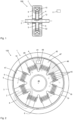
- Figure 2 shows an alternative embodiment in which a ring-cylindrical brake gap 5 is formed between the two brake components 2 and 3.
- a core 7 is formed on the axle unit 42, which core comprises a plurality of radially outwardly projecting arms 47.
- the arms 47 can be finger-like or extend considerably in depth in the form of ribs, so that the length perpendicular to the plane of the sheet can also be greater than the diameter in the plane of the sheet.
- the braking device 1 according to Figure 2 It is possible to slow down or dampen both linear movements perpendicular to the plane of the sheet and rotational movements.
- Each individual arm 47 here has multiple windings of an electrical coil unit 10 to generate a corresponding magnetic field.
- the magnetic field 8 passes essentially radially through the brake gap 5 and extends in the outer brake component 3, which can be designed as a rotor unit 43, in the circumferential direction to the next arm 47, where it passes essentially radially again through the brake gap 5.
- intermediate sections 48 are provided or formed, which are in particular filled with a material having a considerably lower magnetic permeability than the magnetic permeability of the arms 47.
- the ratio of the relative magnetic permeability of the arm 47 to the relative magnetic permeability of the intermediate section 48 is preferably greater than 10 and in particular greater than 100 and particularly preferably greater than 1000 and can reach or exceed values of 10,000 or 100,000.
- a compensation tank 41 can be provided. If “dry” particles 20 with a gas or gas mixture are used as the magnetorheological medium 9, a compensation tank (temperature compensation, leakage compensation, etc.) can be omitted.
- the radially outer end of an arm 47 may be tapered to produce a greater concentration of field strength in the brake gap, cf. the constriction 49 above in the illustration of Figure 2 It is also possible for the radially outer end of one or more arms 47 to have a star contour or a wave shape, as shown in the lower right area, in order to achieve a certain amplification in certain sections above the surface of the arm. Elevations 18 and depressions 19 are shown there. Corresponding contours in the housing, which reduce the effective areas and thus increase the field strength in the transition areas, are also possible as an alternative or in addition.
- Figure 3 shows a highly schematic sectional view through the brake gap of a braking device 1.
- Magnetic field lines 8 are schematically drawn into the braking component 2 and the braking component 3, which pass vertically through the braking gap 54.
- magnetorheological particles 20 are schematically shown, which are non-circular and can therefore form an effective jamming structure 15.
- An edge 29 on one of the magnetorheological particles 20 is shown as an example. It can be seen that the type and structure of the magnetorheological particles 20 ensure effective jamming of the individual particles among themselves and of the two brake components. 2 and 3 relative to each other.
- a smaller gap height is preferred here. If larger particles are used, the effective gap thickness/height can also be larger. If smaller particles are used, the effective gap thickness/height must also be smaller.
- Figure 4 shows a further schematic cross-sectional view of a braking device 1, in which a number of irregularly shaped magnetorheological particles 20 are shown.
- the braking gap extends between the two braking components 2 and 3.
- Several particles 20 are schematically shown in the effective gap or braking gap 5.
- the particle shown at the top right has a maximum diameter 22 that is considerably larger than the maximum transverse extent 23 perpendicular thereto.
- Some of the particles have trough sections 28, projections 16, or recesses 17 into which other sections of other particles can engage. This creates an effective canting structure when the particles engage with one another. Even smaller particles can be located between the particles shown. These can also be spherical.
- the jamming and wedging of the individual particles is promoted by a high magnetic field strength in the braking gap 5, whereby the particles are also attracted to one another, which increases clump formation.
- the mean diameter 21, averaged across all particles, or the typical diameter 24 of the particles 20 may differ from the maximum diameter and the maximum transverse extent 23.
- a large surface area of the particles per volume is advantageous. For example, flatter particles are preferable.
- the surface itself may also be rough and/or corrugated.
- a relatively small minimum gap height 6a is conducive to increasing the braking torque, while an excessively large distance between the two brake components 2 and 3 leads to a reduction in the achievable braking torque. If one or both brake components have an uneven surface, the minimum gap height 6a can be reduced accordingly by adding elevations or depressions.
- Figure 5 shows a schematic representation of a single particle 20, which is formed as a non-circular particle 25.
- the ratio of maximum diameter 22 to maximum transverse extent perpendicular thereto is more than 1.25 and can reach and exceed values of 1.5 or 2.
- Figure 6 shows a highly schematic representation of a device 100 with a braking device 1, wherein rotating bodies 44 in the form of rollers or the like are provided in the braking gap 5.
- the minimum gap height 6a of the braking gap 5 is considerably smaller than the gap height 6 between the braking components 2 and 3.
- irregularly shaped and non-circular particles 25 are used, which lead to clumping and tilting of the individual particles 20, so that a particularly high braking torque can be achieved.
- the magnetically polarizable particles from e.g. Figures 3 to 6 jam, particularly three-dimensionally.
- the active surfaces of the brake components 2 and/or 3 in contact with the particles can also have a corresponding surface and/or surface texture that promotes jamming with the particles. These can have depressions, knurls, pyramids, indentations and protrusions, corners, dimples, and the like.
- the surfaces can be rough and irregular.
- a height difference from the "lowest" to the "highest” point of a surface is greater than 1% or 5% of the gap height in the brake gap 5 and/or greater than 5% or 10% of the diameter of a particle.
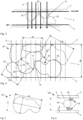
- Figure 7 shows two schematic cross sections of braking devices 1, each with two braking components 2, 3, wherein a braking gap 5 is formed between the surfaces 2b, 3b.
- An electrical coil unit 10 is wound around a core 7, which can be formed in one piece or consists of several parts.
- the core is tapered in the radially outer region and thus has a radially outer constriction 49.
- the magnetic field lines of the magnetic field 8 are concentrated and run "narrower" than in the left illustration of Figure 7 in which the core 7 has no constriction 49 or taper at the radially outer end.
- Elevations 18 and depressions 19 can be formed regularly or irregularly on the surfaces 2b and 3b to promote and reinforce the interlocking of the particles with the brake components. This effectively reinforces the interlocking structure.
- the magnetic field 8 can be specifically amplified at certain points and thus weakened at others.
- Figure 7 This is shown schematically.
- the effective gap which has a larger radius than the core around which the electrical coil unit is wound, therefore has a lower field strength than in core 7, even if the axial diameters are the same as in core 7.
- Increasing the current in the coil unit would no longer be of any use above a certain field strength, since core 7 would enter magnetic saturation.
- different constrictions 49 Different angles
- the remaining web at the braking gap is therefore different in width on the right and left.
- the remaining web is narrower, so that a locally stronger magnetic field passes through the braking gap 5.
- the shearing area is narrower, but the magnetic field strength is significantly higher, so that the particles can become jammed.
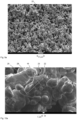
- Figures 9 and 9a show a scanning electron microscope image as a line drawing and as an image of a conventional magnetorheological fluid, with the round particles 20 clearly visible. The scale and a section of 10 ⁇ m are shown at the edge.
- Figures 9 and 9a show essentially the same section.
- Figures 10 and 10a show in principle the same detail.
- Both projections 16 and trough sections 28 are formed on the particles 20.
- a corresponding number of particles 20 designed in this way enables an effective canting structure 15 in the brake gap 5.
- the scale according to Figure 8 (compare the 1 ⁇ m distance shown) is considerably larger than the scale according to Figure 7 , it is clear that the structure of particles 20 in Figure 8 significantly different than in Figure 7 This results in a significantly better clamping of the individual particles 20 among each other and thus of the brake components 2 and 3.
- Particles after Figure 9 (9a) can be treated with particles according to the Figures 3 to 6 and/or 10 (10a) are mixed to form the magnetorheological medium.
- the proportion of non-spherical particles is at least 30%, 40%, or 50% or more.
- the magnetic attraction between particles depends on the volume and the surface area. Spheres have the smallest surface area for a given volume. Since the magnetic attraction is proportional to the (contacting) surface area, the force between two spherical particles is smaller than for differently shaped (non-spherical) particles with the same volume, e.g., cubes or the particle shapes described here. Larger particles therefore attract each other with greater force, since the flux density increases with larger volume.
- Spherical or spherical particles of the same diameter have a maximum packing density that cannot be exceeded. This is approximately 74%. Differently shaped (non-spherical) Particles can be packed more densely. This reduces the empty space or air volume in the gap. The magnetic resistance in the gap decreases, making the magnetic circuit more efficient. The magnetic flux is then increased within the same installation space, which is particularly advantageous in small installation volumes. The particles themselves then amplify the field they require to form the canting structure.
- a particularly low base torque can be achieved, while at the same time a particularly high maximum braking torque can be achieved.
- a particularly high braking torque is achieved with high flux densities in the braking gap and a relatively small minimum gap height 6a, and with non-circular particles 20.
- the particles For smooth, round, or spherical particles, a sufficiently strong magnetic field is necessary to ensure that the particles adhere or rub against one another strongly enough to achieve the desired braking effect. If the magnetic field is insufficient, the particles slide along one another.
- the canting structure forms between the individual particles 20 even under weaker magnetic influences, so that they, for example, clamp together in a form-fitting manner and cannot slide along one another. This allows for particularly strong braking when required.
- the particles due to the properties described here, the particles have the advantage that they also enable a particularly low base torque. This allows the braking components to rotate particularly easily relative to one another when no magnetic field is generated.
Landscapes
- Engineering & Computer Science (AREA)
- General Engineering & Computer Science (AREA)
- Mechanical Engineering (AREA)
- Transportation (AREA)
- Braking Arrangements (AREA)
Claims (15)
- Dispositif (100) avec un dispositif de freinage magnétorhéologique (1) pour le freinage de mouvements relatifs, comprenant au moins deux composants de freinage (2, 3), entre lesdits composants de freinage (2, 3) étant formé un espace de réception (4) avec un espace de freinage (5) qui contient un milieu magnétorhéologique (9) contenant des particules magnétiquement polarisables (20) et influençable par un champ magnétique, dans lequel au moins un noyau et au moins une unité de bobine électrique (24) sont compris afin de générer un champ magnétique commandable (8) dans l'espace de freinage (5),dans lequel au moins une partie des particules magnétiquement polarisables (20) est conçue pour former une structure de calage (15) sous l'influence du champ magnétique (8) et pour se serrer entre elles,caractérisé par le fait que pour au moins 25 % des particules magnétiquement polarisables (20), un rapport du diamètre maximal (22) à l'extension transversale maximale (23) perpendiculaire à celui-ci est supérieur à 1,25, qui sont présentes sous forme de particules non rondes (20a).
- Dispositif (100) selon la revendication 1, dans lequel les particules magnétiquement polarisables (20) comprennent des particules non rondes (20a) dans lesquelles un rapport du diamètre le plus grand/maximal (22) à l'extension transversale la plus grande/maximale (23) perpendiculaire à celui-ci est supérieur à 1,5.
- Dispositif (100) selon l'une quelconque des revendications précédentes, dans lequel au moins une partie des particules magnétiquement polarisables (20) est conçue pour se serrer les unes contre les autres sous l'effet du champ magnétique (8) sur deux ou plusieurs points (26, 27) espacés les uns des autres, et/ou dans lequel au moins une partie des particules magnétiquement polarisables (20) présente au moins une section en creux (28) et/ou dans lequel au moins une partie des particules magnétiquement polarisables (20) présente une section structurelle coudée (30).
- Dispositif (100) selon l'une quelconque des revendications précédentes, dans lequel une saillie ou un bord d'une particule se serre contre un retrait ou une section en creux d'une autre particule
et/ou dans lequel au moins une surface d'au moins un composant de frein (2, 3) adjacente à l'espace de freinage (5) est réalisée, au moins par sections, de manière non lisse et présente des élévations (18) et/ou des dépressions (19) afin de renforcer un calage avec les particules (20). - Dispositif (100) selon l'une quelconque des revendications précédentes, dans lequel une hauteur d'espace minimale (6a) de l'espace de freinage (6) entre les composants de frein (2, 3) est supérieure à deux fois l'extension transversale maximale (23) perpendiculaire au diamètre maximal (22) des particules magnétiquement polarisables (20) dans l'espace de freinage (6).
- Dispositif (100) selon l'une quelconque des revendications précédentes, dans lequel, pour au moins 50 % des particules magnétiquement polarisables (20), un rapport du diamètre maximal (22) à l'extension transversale maximale (23) perpendiculaire à celui-ci est supérieur à 1,25et/ou dans lequel au moins 25 % des particules magnétiquement polarisables (20) présentent un diamètre maximal (22) et/ou une extension transversale maximale (23) d'au moins 10 µm ou d'au moins 20 µmet/ou dans lequel au moins 25 % des particules magnétiquement polarisables (20) présentent un diamètre maximal (22) d'au moins 30 µm ou 50 µm.
- Dispositif (100) selon l'une quelconque des revendications précédentes, dans lequel les deux composants de frein (2, 3) peuvent pivoter l'un par rapport à l'autre et/ou peuvent tourner en continu l'un par rapport à l'autre.
- Dispositif (100) selon l'une quelconque des revendications précédentes, dans lequel l'unité de bobine électrique (10) est enroulée radialement ou axialement autour du noyau (7).
- Dispositif (100) selon l'une quelconque des revendications précédentes, dans lequel l'espace de freinage (5) entoure complètement le composant intérieur (2a) et dans lequel l'espace de freinage (5) est conçu en particulier en tant qu'espace annulaire circonférentiel.
- Dispositif (100) selon l'une quelconque des revendications précédentes, dans lequel un contour en étoile (47) faisant saillie vers l'autre composant de frein respectif est réalisé sur au moins un composant de frein (2, 3), lequel contour en étoile crée/fournit une hauteur d'espace (46) variable sur la circonférence ou la longueur de l'espace de freinage (5).
- Dispositif (100) selon l'une quelconque des revendications précédentes, dans lequel au moins un corps rotatif (44) est disposé dans une section d'espace (45) de l'espace de freinage.
- Dispositif (100) selon l'une quelconque des revendications précédentes, dans lequel le milieu magnétorhéologique (9) comprend au moins un liquide comme milieu porteur dans lequel sont logées les particules magnétiquement polarisables (20), les particules magnétiquement polarisables (20) font en particulier entre 25 et 50 % en volume dans l'espace de réception (4) ou dans lequel le milieu magnétorhéologique (9) comprend au moins un gaz en tant que milieu porteur entourant les particules magnétiquement polarisables (20), dans lequel les particules magnétiquement polarisables (20) font en particulier entre 40 et 90 % en volume dans l'espace de réception (4).
- Dispositif (100) selon l'une quelconque des revendications précédentes, comprenant un élément de commande (101) relié au dispositif de freinage magnétorhéologique (1), et dans lequel l'élément de commande (100) comprend un rouleau de commande (103) et/ou un bouton de commande (104), et dans lequel le dispositif de freinage magnétorhéologique (1) est logé au moins en partie à l'intérieur de l'élément de commande (101).
- Procédé (100) de freinage de mouvements relatifs d'au moins deux composants de frein (2, 3) d'un dispositif de freinage magnétorhéologique (1), dans lequel un espace de réception (4) avec un espace de freinage (5) est formé entre les composants de frein (2, 3) et contient un milieu magnétorhéologique (9) contenant des particules magnétiquement polarisables (20) et influençable par un champ magnétique, dans lequel un champ magnétique (8) est généré dans l'espace de freinage (5) par une unité de bobine électrique (24) afin de former une structure de calage (15) sur au moins une partie des particules magnétiquement polarisables (20) dans l'espace de freinage sous l'influence du champ magnétique (8) et afin de caler des particules magnétiquement polarisables (20) entre elles sur celle-ci.
et que pour au moins 25 % des particules magnétiquement polarisables (20) utilisées, un rapport du diamètre maximal (22) à l'extension transversale maximale (23) perpendiculaire à celui-ci est supérieur à 1,25, qui sont présentes sous forme de particules non rondes (20a). - Procédé selon la revendication précédente, dans lequel l'intensité du champ magnétique entre les particules individuelles est supérieure à 500 kA/m et dans lequel la concentration de particules dans l'espace de freinage est supérieure à 40 %.
Priority Applications (1)
| Application Number | Priority Date | Filing Date | Title |
|---|---|---|---|
| EP25183280.4A EP4607055A3 (fr) | 2021-07-06 | 2022-07-05 | Appareil comprenant un dispositif de freinage magnétorhéologique et procédé |
Applications Claiming Priority (3)
| Application Number | Priority Date | Filing Date | Title |
|---|---|---|---|
| DE102021117398 | 2021-07-06 | ||
| DE102021118223 | 2021-07-14 | ||
| PCT/EP2022/068556 WO2023280837A1 (fr) | 2021-07-06 | 2022-07-05 | Appareil comprenant un dispositif de freinage magnéto-rhéologique et procédé |
Related Child Applications (1)
| Application Number | Title | Priority Date | Filing Date |
|---|---|---|---|
| EP25183280.4A Division EP4607055A3 (fr) | 2021-07-06 | 2022-07-05 | Appareil comprenant un dispositif de freinage magnétorhéologique et procédé |
Publications (3)
| Publication Number | Publication Date |
|---|---|
| EP4366995A1 EP4366995A1 (fr) | 2024-05-15 |
| EP4366995B1 true EP4366995B1 (fr) | 2025-06-18 |
| EP4366995C0 EP4366995C0 (fr) | 2025-06-18 |
Family
ID=82655364
Family Applications (2)
| Application Number | Title | Priority Date | Filing Date |
|---|---|---|---|
| EP25183280.4A Pending EP4607055A3 (fr) | 2021-07-06 | 2022-07-05 | Appareil comprenant un dispositif de freinage magnétorhéologique et procédé |
| EP22744442.9A Active EP4366995B1 (fr) | 2021-07-06 | 2022-07-05 | Appareil comprenant un dispositif de freinage magnéto-rhéologique et procédé |
Family Applications Before (1)
| Application Number | Title | Priority Date | Filing Date |
|---|---|---|---|
| EP25183280.4A Pending EP4607055A3 (fr) | 2021-07-06 | 2022-07-05 | Appareil comprenant un dispositif de freinage magnétorhéologique et procédé |
Country Status (4)
| Country | Link |
|---|---|
| US (1) | US20240392847A1 (fr) |
| EP (2) | EP4607055A3 (fr) |
| DE (1) | DE102021118281A1 (fr) |
| WO (1) | WO2023280837A1 (fr) |
Families Citing this family (3)
| Publication number | Priority date | Publication date | Assignee | Title |
|---|---|---|---|---|
| DE102019135760A1 (de) * | 2019-12-18 | 2021-06-24 | Inventus Engineering Gmbh | Magnetorheologische Bremseinrichtung |
| DE102022115750A1 (de) * | 2022-06-24 | 2024-01-04 | Signata GmbH | Stellvorrichtung für ein Fahrzeug und Verfahren zum Betreiben einer Stellvorrichtung |
| DE102023112574A1 (de) * | 2023-05-11 | 2024-11-14 | Inventus Engineering Gmbh | Vorrichtung mit einer magnetorheologischen Übertragungseinrichtung und einer Sensoreinrichtung |
Family Cites Families (6)
| Publication number | Priority date | Publication date | Assignee | Title |
|---|---|---|---|---|
| US7217372B2 (en) * | 2000-05-03 | 2007-05-15 | Lord Corporation | Magnetorheological composition |
| US6610404B2 (en) * | 2001-02-13 | 2003-08-26 | Trw Inc. | High yield stress magnetorheological material for spacecraft applications |
| DE102010055833A1 (de) | 2010-09-15 | 2012-03-15 | Inventus Engineering Gmbh | Rheologische Übertragungsvorrichtung |
| JP5695588B2 (ja) | 2012-03-01 | 2015-04-08 | 株式会社栗本鐵工所 | 磁気粘性流体及びこれを用いたクラッチ |
| DE102018100390A1 (de) | 2018-01-10 | 2019-07-11 | Inventus Engineering Gmbh | Magnetorheologische Bremseinrichtung |
| DE102019135760A1 (de) | 2019-12-18 | 2021-06-24 | Inventus Engineering Gmbh | Magnetorheologische Bremseinrichtung |
-
2021
- 2021-07-15 DE DE102021118281.6A patent/DE102021118281A1/de active Pending
-
2022
- 2022-07-05 WO PCT/EP2022/068556 patent/WO2023280837A1/fr not_active Ceased
- 2022-07-05 EP EP25183280.4A patent/EP4607055A3/fr active Pending
- 2022-07-05 US US18/573,462 patent/US20240392847A1/en active Pending
- 2022-07-05 EP EP22744442.9A patent/EP4366995B1/fr active Active
Also Published As
| Publication number | Publication date |
|---|---|
| EP4607055A3 (fr) | 2025-10-08 |
| EP4366995A1 (fr) | 2024-05-15 |
| EP4366995C0 (fr) | 2025-06-18 |
| WO2023280837A1 (fr) | 2023-01-12 |
| DE102021118281A1 (de) | 2023-01-12 |
| US20240392847A1 (en) | 2024-11-28 |
| EP4607055A2 (fr) | 2025-08-27 |
Similar Documents
| Publication | Publication Date | Title |
|---|---|---|
| EP4366995B1 (fr) | Appareil comprenant un dispositif de freinage magnéto-rhéologique et procédé | |
| EP3737873B1 (fr) | Dispositif de freinage magnétorhéologique | |
| EP2989254B1 (fr) | Dispositif d'appui coulissant pour ouvrage et procédé de dimensionnement | |
| DE102012017423B4 (de) | Magnetorheologische Übertragungseinrichtung | |
| DE69114454T2 (de) | Dichtung mit Druckfeder. | |
| DE69400974T2 (de) | Stossverzehrelement mit stetigem Verformungswiderstand | |
| DE69620972T2 (de) | Kupplungsscheibe für Reibungskupplungsvorrichtung | |
| EP2150717B2 (fr) | Dispositif de transmission de couple magnétorhéologique, son procédé d'utilisation, et procédé de transmission de couple magnétorhéologique associé | |
| DE102009039279A1 (de) | Dichtungsvorrichtung | |
| EP0419684A1 (fr) | Element de frottement dans un couple de frottement | |
| DE3539608A1 (de) | Schraubenfeder und ihre verwendung | |
| DE4440725A1 (de) | Lageranordnung zur spielfreien Einstellung einer Welle, insbesondere einer Lenkwelle in einer Lenksäule | |
| WO2014012602A1 (fr) | Rondelle ondulée présentant une caractéristique linéaire dans certaines zones | |
| DE3204385A1 (de) | Vorrichtung zur begrenzung der differentialbewegung in einem differentialgetriebe | |
| DE10233938B4 (de) | Elektromechanische Bremsanlage mit einem Maschinenelement mit zwischen beweglichen Bauteilen angeordneten Wälzkörpern | |
| DE102019135026A1 (de) | Gerätekomponente mit einer magnetorheologischen Bremseinrichtung | |
| DE102019135027B3 (de) | Gerätekomponente für eine magnetorheologische Bremseinrichtung mit Temperaturausgleich | |
| DE2234428A1 (de) | Verfahren zur verbesserung der verschleisseigenschaften zweier sich gegeneinander bewegender flaechen | |
| DE60203984T2 (de) | Kugelgewindetrieb mit hoher Lebendsdauer und reduziertem Geräusch | |
| EP2580010B1 (fr) | Outil de compactage | |
| DE69402188T2 (de) | Verbindungen mit spalten | |
| DE2610707B1 (de) | Einstueckiger abstandskoerper fuer waelzlager | |
| DE102008050231A1 (de) | Wälzkörper | |
| DE60209992T2 (de) | Linearführung und Walzbacken zu ihrer Herstellung | |
| EP3655681B1 (fr) | Dispositif d'étanchéité comportant des cavités |
Legal Events
| Date | Code | Title | Description |
|---|---|---|---|
| STAA | Information on the status of an ep patent application or granted ep patent |
Free format text: STATUS: UNKNOWN |
|
| STAA | Information on the status of an ep patent application or granted ep patent |
Free format text: STATUS: THE INTERNATIONAL PUBLICATION HAS BEEN MADE |
|
| PUAI | Public reference made under article 153(3) epc to a published international application that has entered the european phase |
Free format text: ORIGINAL CODE: 0009012 |
|
| STAA | Information on the status of an ep patent application or granted ep patent |
Free format text: STATUS: REQUEST FOR EXAMINATION WAS MADE |
|
| 17P | Request for examination filed |
Effective date: 20240131 |
|
| AK | Designated contracting states |
Kind code of ref document: A1 Designated state(s): AL AT BE BG CH CY CZ DE DK EE ES FI FR GB GR HR HU IE IS IT LI LT LU LV MC MK MT NL NO PL PT RO RS SE SI SK SM TR |
|
| DAV | Request for validation of the european patent (deleted) | ||
| DAX | Request for extension of the european patent (deleted) | ||
| GRAP | Despatch of communication of intention to grant a patent |
Free format text: ORIGINAL CODE: EPIDOSNIGR1 |
|
| STAA | Information on the status of an ep patent application or granted ep patent |
Free format text: STATUS: GRANT OF PATENT IS INTENDED |
|
| INTG | Intention to grant announced |
Effective date: 20250310 |
|
| GRAS | Grant fee paid |
Free format text: ORIGINAL CODE: EPIDOSNIGR3 |
|
| GRAA | (expected) grant |
Free format text: ORIGINAL CODE: 0009210 |
|
| STAA | Information on the status of an ep patent application or granted ep patent |
Free format text: STATUS: THE PATENT HAS BEEN GRANTED |
|
| AK | Designated contracting states |
Kind code of ref document: B1 Designated state(s): AL AT BE BG CH CY CZ DE DK EE ES FI FR GB GR HR HU IE IS IT LI LT LU LV MC MK MT NL NO PL PT RO RS SE SI SK SM TR |
|
| REG | Reference to a national code |
Ref country code: GB Ref legal event code: FG4D Free format text: NOT ENGLISH |
|
| REG | Reference to a national code |
Ref country code: CH Ref legal event code: EP |
|
| REG | Reference to a national code |
Ref country code: DE Ref legal event code: R096 Ref document number: 502022004345 Country of ref document: DE |
|
| REG | Reference to a national code |
Ref country code: CH Ref legal event code: EP |
|
| REG | Reference to a national code |
Ref country code: IE Ref legal event code: FG4D Free format text: LANGUAGE OF EP DOCUMENT: GERMAN |
|
| U01 | Request for unitary effect filed |
Effective date: 20250707 |
|
| U07 | Unitary effect registered |
Designated state(s): AT BE BG DE DK EE FI FR IT LT LU LV MT NL PT RO SE SI Effective date: 20250711 |
|
| U20 | Renewal fee for the european patent with unitary effect paid |
Year of fee payment: 4 Effective date: 20250714 |
|
| PG25 | Lapsed in a contracting state [announced via postgrant information from national office to epo] |
Ref country code: NO Free format text: LAPSE BECAUSE OF FAILURE TO SUBMIT A TRANSLATION OF THE DESCRIPTION OR TO PAY THE FEE WITHIN THE PRESCRIBED TIME-LIMIT Effective date: 20250918 Ref country code: GR Free format text: LAPSE BECAUSE OF FAILURE TO SUBMIT A TRANSLATION OF THE DESCRIPTION OR TO PAY THE FEE WITHIN THE PRESCRIBED TIME-LIMIT Effective date: 20250919 |
|
| PG25 | Lapsed in a contracting state [announced via postgrant information from national office to epo] |
Ref country code: HR Free format text: LAPSE BECAUSE OF FAILURE TO SUBMIT A TRANSLATION OF THE DESCRIPTION OR TO PAY THE FEE WITHIN THE PRESCRIBED TIME-LIMIT Effective date: 20250618 |
|
| PG25 | Lapsed in a contracting state [announced via postgrant information from national office to epo] |
Ref country code: RS Free format text: LAPSE BECAUSE OF FAILURE TO SUBMIT A TRANSLATION OF THE DESCRIPTION OR TO PAY THE FEE WITHIN THE PRESCRIBED TIME-LIMIT Effective date: 20250918 |