EP2989254B1 - Dispositif d'appui coulissant pour ouvrage et procédé de dimensionnement - Google Patents
Dispositif d'appui coulissant pour ouvrage et procédé de dimensionnement Download PDFInfo
- Publication number
- EP2989254B1 EP2989254B1 EP14714244.2A EP14714244A EP2989254B1 EP 2989254 B1 EP2989254 B1 EP 2989254B1 EP 14714244 A EP14714244 A EP 14714244A EP 2989254 B1 EP2989254 B1 EP 2989254B1
- Authority
- EP
- European Patent Office
- Prior art keywords
- sliding
- bearing
- structural
- friction
- contact surface
- Prior art date
- Legal status (The legal status is an assumption and is not a legal conclusion. Google has not performed a legal analysis and makes no representation as to the accuracy of the status listed.)
- Active
Links
- 238000000034 method Methods 0.000 title claims description 12
- 239000000463 material Substances 0.000 claims description 46
- 125000006850 spacer group Chemical group 0.000 claims description 13
- 239000004699 Ultra-high molecular weight polyethylene Substances 0.000 claims description 5
- 230000002093 peripheral effect Effects 0.000 claims description 5
- 229920000785 ultra high molecular weight polyethylene Polymers 0.000 claims description 5
- 239000004810 polytetrafluoroethylene Substances 0.000 claims description 4
- 229920001343 polytetrafluoroethylene Polymers 0.000 claims description 4
- 239000004952 Polyamide Substances 0.000 claims description 3
- 229920002647 polyamide Polymers 0.000 claims description 3
- 229920001169 thermoplastic Polymers 0.000 claims description 2
- 239000004416 thermosoftening plastic Substances 0.000 claims description 2
- 230000000717 retained effect Effects 0.000 claims 1
- YBJHBAHKTGYVGT-ZKWXMUAHSA-N (+)-Biotin Chemical compound N1C(=O)N[C@@H]2[C@H](CCCCC(=O)O)SC[C@@H]21 YBJHBAHKTGYVGT-ZKWXMUAHSA-N 0.000 description 10
- 238000013461 design Methods 0.000 description 10
- FEPMHVLSLDOMQC-UHFFFAOYSA-N virginiamycin-S1 Natural products CC1OC(=O)C(C=2C=CC=CC=2)NC(=O)C2CC(=O)CCN2C(=O)C(CC=2C=CC=CC=2)N(C)C(=O)C2CCCN2C(=O)C(CC)NC(=O)C1NC(=O)C1=NC=CC=C1O FEPMHVLSLDOMQC-UHFFFAOYSA-N 0.000 description 10
- 230000000694 effects Effects 0.000 description 9
- 238000011161 development Methods 0.000 description 7
- 230000018109 developmental process Effects 0.000 description 7
- 238000004519 manufacturing process Methods 0.000 description 7
- 230000013011 mating Effects 0.000 description 6
- 238000005461 lubrication Methods 0.000 description 5
- 238000002955 isolation Methods 0.000 description 4
- 238000003860 storage Methods 0.000 description 4
- 238000006243 chemical reaction Methods 0.000 description 3
- 238000010276 construction Methods 0.000 description 3
- 230000007423 decrease Effects 0.000 description 3
- 238000005259 measurement Methods 0.000 description 3
- 238000007493 shaping process Methods 0.000 description 3
- 238000012360 testing method Methods 0.000 description 3
- VYZAMTAEIAYCRO-UHFFFAOYSA-N Chromium Chemical compound [Cr] VYZAMTAEIAYCRO-UHFFFAOYSA-N 0.000 description 2
- 229910000831 Steel Inorganic materials 0.000 description 2
- 230000033228 biological regulation Effects 0.000 description 2
- 238000004364 calculation method Methods 0.000 description 2
- 230000006378 damage Effects 0.000 description 2
- 238000010586 diagram Methods 0.000 description 2
- 238000006073 displacement reaction Methods 0.000 description 2
- 238000002474 experimental method Methods 0.000 description 2
- 238000003801 milling Methods 0.000 description 2
- 239000000203 mixture Substances 0.000 description 2
- 230000021715 photosynthesis, light harvesting Effects 0.000 description 2
- 239000010959 steel Substances 0.000 description 2
- 102000016550 Complement Factor H Human genes 0.000 description 1
- 108010053085 Complement Factor H Proteins 0.000 description 1
- 238000013459 approach Methods 0.000 description 1
- 238000005266 casting Methods 0.000 description 1
- 239000011248 coating agent Substances 0.000 description 1
- 238000000576 coating method Methods 0.000 description 1
- 239000002131 composite material Substances 0.000 description 1
- 230000006835 compression Effects 0.000 description 1
- 238000007906 compression Methods 0.000 description 1
- 230000008094 contradictory effect Effects 0.000 description 1
- 230000001419 dependent effect Effects 0.000 description 1
- 238000003780 insertion Methods 0.000 description 1
- 230000037431 insertion Effects 0.000 description 1
- 238000009413 insulation Methods 0.000 description 1
- 239000012212 insulator Substances 0.000 description 1
- 238000011835 investigation Methods 0.000 description 1
- 238000005457 optimization Methods 0.000 description 1
- 239000004033 plastic Substances 0.000 description 1
- 229920003023 plastic Polymers 0.000 description 1
- 238000007747 plating Methods 0.000 description 1
- 230000002265 prevention Effects 0.000 description 1
- 238000005245 sintering Methods 0.000 description 1
- 239000007858 starting material Substances 0.000 description 1
- 238000010971 suitability test Methods 0.000 description 1
- 239000012815 thermoplastic material Substances 0.000 description 1
Images


Classifications
-
- E—FIXED CONSTRUCTIONS
- E01—CONSTRUCTION OF ROADS, RAILWAYS, OR BRIDGES
- E01D—CONSTRUCTION OF BRIDGES, ELEVATED ROADWAYS OR VIADUCTS; ASSEMBLY OF BRIDGES
- E01D19/00—Structural or constructional details of bridges
- E01D19/04—Bearings; Hinges
- E01D19/042—Mechanical bearings
-
- E—FIXED CONSTRUCTIONS
- E01—CONSTRUCTION OF ROADS, RAILWAYS, OR BRIDGES
- E01D—CONSTRUCTION OF BRIDGES, ELEVATED ROADWAYS OR VIADUCTS; ASSEMBLY OF BRIDGES
- E01D19/00—Structural or constructional details of bridges
- E01D19/04—Bearings; Hinges
- E01D19/042—Mechanical bearings
- E01D19/046—Spherical bearings
-
- E—FIXED CONSTRUCTIONS
- E01—CONSTRUCTION OF ROADS, RAILWAYS, OR BRIDGES
- E01D—CONSTRUCTION OF BRIDGES, ELEVATED ROADWAYS OR VIADUCTS; ASSEMBLY OF BRIDGES
- E01D19/00—Structural or constructional details of bridges
- E01D19/04—Bearings; Hinges
- E01D19/042—Mechanical bearings
- E01D19/047—Pot bearings
-
- E—FIXED CONSTRUCTIONS
- E02—HYDRAULIC ENGINEERING; FOUNDATIONS; SOIL SHIFTING
- E02D—FOUNDATIONS; EXCAVATIONS; EMBANKMENTS; UNDERGROUND OR UNDERWATER STRUCTURES
- E02D27/00—Foundations as substructures
- E02D27/32—Foundations for special purposes
- E02D27/34—Foundations for sinking or earthquake territories
-
- E—FIXED CONSTRUCTIONS
- E04—BUILDING
- E04B—GENERAL BUILDING CONSTRUCTIONS; WALLS, e.g. PARTITIONS; ROOFS; FLOORS; CEILINGS; INSULATION OR OTHER PROTECTION OF BUILDINGS
- E04B1/00—Constructions in general; Structures which are not restricted either to walls, e.g. partitions, or floors or ceilings or roofs
- E04B1/36—Bearings or like supports allowing movement
-
- F—MECHANICAL ENGINEERING; LIGHTING; HEATING; WEAPONS; BLASTING
- F16—ENGINEERING ELEMENTS AND UNITS; GENERAL MEASURES FOR PRODUCING AND MAINTAINING EFFECTIVE FUNCTIONING OF MACHINES OR INSTALLATIONS; THERMAL INSULATION IN GENERAL
- F16C—SHAFTS; FLEXIBLE SHAFTS; ELEMENTS OR CRANKSHAFT MECHANISMS; ROTARY BODIES OTHER THAN GEARING ELEMENTS; BEARINGS
- F16C33/00—Parts of bearings; Special methods for making bearings or parts thereof
- F16C33/02—Parts of sliding-contact bearings
- F16C33/04—Brasses; Bushes; Linings
- F16C33/20—Sliding surface consisting mainly of plastics
Definitions
- the invention relates to a building sliding bearing, with at least a first bearing part is attached to the at least one sliding member and a relatively displaceably arranged second bearing member which forms a sliding surface in mating with a contact surface of the sliding element, which allows sliding movements between the two bearing parts.
- the invention further relates to a method for dimensioning a building journal bearing.
- Structural plain bearings are a special design of a building warehouse.
- Structural bearings also referred to as bearings in construction, serve in general the defined and as constraint-free storage of any type of structures, such as bridges, beams, houses, towers or parts thereof. They thus allow relative movements between two components of the relevant structure.
- the European standard EN 1337 various types and functions are known. Depending on the design and mode of operation, the building bearings have a different structure and a different number of degrees of freedom.
- Structural plain bearings hereinafter also referred to as plain bearings, have at least a first bearing part on which at least one sliding element is fastened and a second bearing part arranged for this purpose in a relatively displaceable manner.
- the second bearing part forms in pair with the contact surface of the sliding element of the first bearing part a sliding surface which allows sliding movements between the two bearing parts.
- the sliding element usually consists of a sliding material.
- a sliding material are various plastics with low friction such as PTFE, UHMWPE or polyamide used.
- Composites such as the CM1 and CM2 mentioned in EN 1337-2 are also used.
- the surface of the second bearing part usually has a special surface coating, such as a hard chrome plating, when it interacts directly with the sliding element.
- the second bearing part can also interact insofar indirectly with the sliding element, as it in turn still has a counter-sliding element.
- This may be a so-called sliding plate, e.g. austenitic steel sheet, which has been applied to the second bearing part and in turn has a defined surface quality.
- the EN 1337 contains regulations such as the sliding element, the any counter-sliding element and the associated support elements and bearing parts are to be executed.
- the aim is the lowest possible sliding resistance in a relative displacement or - rotation of the separated by the sliding bearing structures or building parts.
- an upper design value of the friction coefficient is usually used on the safe side.
- the sliding resistance is defined here via the friction coefficient.
- the friction coefficient is the quotient of the force required for the movement in the direction of the sliding movement and the force acting at right angles to the sliding surface
- sliding bearings In addition to the movable bearings of buildings sliding bearings have been used for some time for the isolation of structures or parts thereof from other surrounding structures and / or from the ground.
- the aim of such insulation can be, for example, the prevention of structural damage as a result of earthquakes.
- a special type of construction of such a plain bearing serving the isolation is the so-called Gleitpendellager.
- the at least one sliding surface is curved. The curvature of the sliding surface causes restoring forces to be generated in the case of horizontal deflection. Regulations for such bearings are given for example in the European standard EN 15129.
- the decisive parameter for the friction between two moving bodies is, as mentioned, the coefficient of friction.
- the coefficient of friction is substantially controlled by the choice of the sliding and mating material, the type of lubrication of the sliding surface and the contact pressure.
- Appropriate plain bearings are in the documents WO 2009/010487 A1 and JP 2007 016905 A described.
- the structural sliding bearing according to the invention is thus characterized in that the shape of the contact surface of the sliding element is designed so that a desired coefficient of friction is set in the sliding surface.
- the invention is based on the finding that the friction coefficient changes with the same sliding material with the shape of the contact surface of the sliding element and you can use this behavior for targeted adjustment of the coefficient of friction and thus the friction of the structure-sliding bearing.
- the frictional behavior of the sliding bearing is therefore not set as usual by the choice of the sliding and mating material, the type of lubrication of the sliding surface and the contact pressure. Rather, by a targeted shaping of the contact surface of the sliding element, the coefficient of friction in the desired manner and thus influenced by another decisive parameter. For attempts by the Applicant have shown that in structural plain bearings different deformation behavior of the sliding material in the center of the contact surface and at the edge of the contact surface adjust the sliding resistance and you can specifically use this effect to set a desired friction behavior in the sliding surface.
- the desired coefficient of friction in the sliding surface is set as a function of the circumferential length and / or the planform of the contact surface and / or the sliding gap height and / or the orientation of the edges of the contact surface with respect to the sliding direction.
- edges which run parallel to the sliding direction have a smaller influence on the coefficient of friction than those edges which run orthogonally to the direction of friction.
- a defined orientation of the free lateral surface in the direction of the various degrees of freedom of the structural sliding bearing causes different friction numbers and thus frictional resistances in the direction of the various degrees of freedom.
- the influence of the individual shaping of the sliding surface plan on the coefficient of friction is represented by a form factor.
- the Gleithotelriss rather roundish outline edges or pointed corners has as well as the respective number of edges and their distance and orientation to Gleit vomech.
- the Gleitspalt Turner can be used to influence the coefficient of friction in the sliding surface.
- the coefficient of friction is lowered, but even with very low sliding gaps, the effect of influencing the coefficient of friction is only partially. Consequently, depending on the desired effect on the coefficient of friction, an optimum slide gap height may exist.
- the slide bearing By selectively influencing the friction behavior of the sliding bearing on the shape of the sliding element can be adapted to different tasks and purposes in a very simple way, the slide bearing. To apply for this without extensive aptitude tests or special approvals. Rather, it is so possible with one and the same sliding material for which one has already obtained, for example, an approval as a sliding material to solve different tasks. So you can build with the material for a normal slide bearing, or by increasing the proportion of the lateral surface of the sliding element an earthquake insulator, which should have a comparatively increased friction in the respective sliding surface.
- the invention has the effect that it does not have to come to storage of different materials in the production more. This reduces the storage costs, prevents confusion in the production of the bearings and brings advantages in purchasing.
- the coefficient of friction in the sliding surface is set as a function of a shape factor taking into account the ratio of contact surface to free lateral surface of the sliding element.
- the form factor is a quotient of the contact surface to the free lateral surface, wherein the free lateral surface as already mentioned, the length of the circumference of the contact surface multiplied by the height of the sliding gap.
- the size of the contact surface of the sliding element has been optimized, preferably minimized, as a function of the shape factor, such that the desired coefficient of friction in the sliding surface is achieved without a change in the pressure.
- the building plain bearings for the particular purpose can be made smaller and thus more economical.
- the shape of the sliding element is designed so that the size of the coefficient of friction in the sliding surface has been maximized as a function of the shape factor.
- the shape factor For the practical application means that by increasing the free lateral surface with the same contact surface, the structural plain bearing a maximum friction coefficient and thus a maximum dissipation capacity can be achieved.
- the enlargement of the free lateral surface can be done, for example, by changing the shape of the contact surface.
- the contact surface may have an oval or star-shaped shape or any other conceivable shape which results in a larger free lateral surface.
- the structural sliding bearing is preferably designed as a spherical bearing, in particular as a sliding pendulum bearing.
- Characteristic of Kalottenlager is that they have at least one curved sliding surface, while Gleitpendellager have multiple curved sliding surfaces.
- the coefficient of friction is set differently in different sliding surfaces but consisting of the same sliding material as described above.
- a sliding surface for the normal condition of use can be designed as a conventional friction bearing with low friction, while a second sliding surface is designed especially with regard to an earthquake with an increased coefficient of friction, ie an increased dissipation capacity.
- the contact surface of the sliding element is formed from two, in particular more than four, partial contact surfaces.
- the subdivision of the contact surface according to the invention into partial contact surfaces causes an enlargement of the free lateral surface of the sliding element.
- Such a subdivision can be effected by a plurality of sliding elements or by notching or the like.
- the subdivision facilitates the production because it can be relatively easily produced and little on the basic geometry of the sliding element or its starting materials must be changed (usually plates of certain thickness of a sliding material).
- the sliding element has at least one sliding disk, wherein the contact surface is formed from at least part of the surface of the at least one sliding disk.
- the sliding element thus has a conventional sliding disk known per se and can even consist entirely of it.
- At least part of the surface of the at least one sliding disk is divided by at least one recess into partial contact surfaces.
- a recess may for example be one or more grooves, which is applied in a part of the surface of the at least one sliding disk. The application of these one or more grooves, for example by milling into a part of the surface of the at least one sliding disk.
- the application of recesses in the sliding material is a particularly economical method to produce partial contact surfaces.
- the width of the recess is between a few millimeters and twice the thickness of the first bearing part, on the one hand to ensure sufficient support of the sliding material and on the other hand to distribute the pressure evenly in the adjacent components.
- the division of at least a part of the surface of the at least one sliding disk in turn causes the free lateral surface of the sliding element increases in relation to the contact surface and thus the shape factor is influenced.
- the at least one recess can be shaped as desired in order to produce any partial contact surfaces.
- the recess is designed such that it is elongated or has the shape of a circle, ring or a segment of one of the two.
- manufacturing methods such as turning or milling are suitable because of their great flexibility.
- the recess can also already be produced during the production of the sliding elements, for example during casting or sintering presses in plate form.
- the plain bearing or the sliding material of the sliding disk is exposed to high pressure
- at least one spacer is inserted into at least one recess.
- the insertion of a spacer into the recess ensures that the sliding material of the sliding disk at the edge of the part-contact surfaces under the load can not escape laterally.
- the sliding disk is chambered inwards. Due to the internal chambering, the sliding disks and the structural plain bearing can be made smaller with the same load, or with the same size of the sliding disk, higher loads can be removed with the structural plain bearing.
- the sliding element has a multiplicity of sliding disks. This makes it possible to assemble the sliding element on the one hand from the same and / or differently shaped sliding disks and on the other hand also variably build up the sliding element by the use of sliding disks made of different sliding materials. Furthermore, it is also possible to assemble large and / or individually shaped sliding elements from a multiplicity of standardized sliding disks, as a result of which the production of the structural sliding bearing according to the invention becomes particularly economical.
- the contact surface and / or at least one partial contact surface preferably has the shape of a circle, a ring or a segment of one of the two. This shape has the advantage that no or only a few corners arise that would lead to a punctual increase in friction. This shape helps to keep wear low.
- An advantageous development of the building journal bearing provides that the sliding element and / or at least one sliding disk of the sliding element is kept chambered in the first bearing part.
- the chambered position of the sliding element or the at least one sliding disk reduces the flow of the sliding material as a result of the pressure resulting from the structural loads.
- the type of chambering also has an influence on the size of the free lateral surface, since this is dependent on the height of the sliding gap, in other words the height of the projection of the sliding element on the first bearing part.
- At least one spacer is arranged between two sliding disks.
- This spacer is usually between a few millimeters and twice the thickness of the first bearing part wide. This ensures that on the one hand sufficient support or inner chambering of the Gleittechniksstoffs is guaranteed against flow. On the other hand, it is ensured that the pressure is evenly distributed in the adjacent components.
- the sliding element and / or at least one sliding disk preferably consists at least partially of a sliding material, in particular a thermoplastic sliding material.
- Thermoplastic materials can be well cast in molds, for example, already has webs for generating recesses for subdivision into partial contact surfaces.
- the sliding element and / or at least one sliding disk consists at least partially of PTFE, UHMWPE, polyamide and / or a combination of at least two such materials.
- the method according to the invention for dimensioning a structural plain bearing provides that the coefficient of friction in the sliding surface is set taking into account a shape factor.
- the approach of the invention is based on the fact that the friction is deliberately adjusted by influencing the shape of the contact surface not by influencing material or force sizes but by influencing geometric variables. Accordingly, by shaping the contact surface of the sliding element, the coefficient of friction can be influenced in an astonishingly simple and very flexible manner.
- the dimensioning of the structural sliding bearing is preferably carried out by setting the desired coefficient of friction in the sliding surface as a function of the circumferential length and / or the planform of the contact surface and / or the sliding gap height and / or the alignment of the edges of the contact surface with respect to the sliding direction.
- the coefficient of friction it is conceivable that in the calculation method of the coefficient of friction the influence of the circumferential length, planform of the contact surface, sliding gap height and orientation of the edges to the displacement direction is taken into account via individual coefficients.
- the method according to the invention provides that the coefficient of friction in the Sliding surface is set as a function of a ratio of contact surface to free lateral surface of the sliding element taking into account form factor.
- the form factor is a quotient of the contact surface to the free lateral surface.
- the size of the contact surface of the sliding element is optimized as a function of the shape factor, preferably minimized so that the desired coefficient of friction is achieved in the sliding surface.
- the size of the coefficient of friction in the sliding surface can be maximized as a function of the shape factor. This makes sense especially if the warehouse is to be designed for earthquake isolation.
- the dimensioning is carried out so that the material pairing is kept constant in the sliding surface in the optimization. This allows a simplified dimensioning of the plain bearings.
- Fig. 1 shows a first embodiment of a building journal bearing 10 according to the invention.
- This basically corresponds in construction to the structural plain bearings described in EN 1337. It has a first bearing part 15, a sliding element 20 fastened thereto and a second bearing part 25.
- the second bearing part 25 in turn has a mating surface 55, which in the present case is designed as a hard chrome layer, but could also consist of a sliding plate made of austenitic steel or the like.
- the first bearing part 15 and the second bearing part 25 are designed to be displaceable relative to each other, so that a sliding surface 30 is formed from the pairing of the presently planar surfaces of the sliding element 20 and the counter surface 55.
- the sliding element 20 in the present case consists of a flat sliding disk of a sliding material and is held by means of chambering in the first bearing part 15.
- FIG. 2 a schematic section through a second embodiment of a building journal bearing 10 according to the invention with a curved sliding surface 30 is shown.
- This exemplary embodiment also has a first bearing part 15, a plate-shaped sliding element 20 and a second bearing part 25 displaceable therefor.
- the sliding member 20 is engaged with the second bearing portion 25 via the contact surface A K of the slider 20 to the second bearing member 25 in contact. Since here, too, the sliding element 20 is kept chambered in the first bearing part 15, the free lateral surface A M results from the product of the circumferential length with the height of the sliding gap h, ie the thickness of the plate-shaped sliding element 20 t P minus the depth of the chambering.
- the first bearing part 15 and the second bearing part 25 with a mating surface 55 can be seen.
- the sliding element 20 is composed in the illustrated first embodiment of several sliding disks 35 together.
- the sliding discs 35 are kept chambered in the first bearing part 15.
- the contact surface A K is interrupted in the sliding surface 30 and increases the proportion of the free lateral surface A M relative to the contact surface A K of the sliding element.
- influence on the form factor S can be taken via the geometric configuration of the surface of the sliding element 20.
- the coefficient of friction Y compared to a continuous sliding disk.
- the inserted spacers 45 may also be a web material fit on the first bearing member 15 may be present.
- Fig. 4 is a detailed view of a section through a fourth embodiment of a building journal bearing 10 with a slider, consisting of a single curved sliding disk 35 whose top is divided by recesses 40 into a plurality of partial contact surfaces.
- recesses 40 are applied so that they interrupt the surface of the sliding disk 35.
- the contact surface A K is articulated in the sliding surface 30 and the size of the free circumferential surface AM of the sliding disk 35 or of the sliding element 20 is increased.
- the friction coefficient Y increases.
- a Gleitpendellager which has two sliding surfaces 30 and two sliding elements 20 each having a contact surface A K. Both contact surfaces of the sliding elements 20 can be designed so that a desired coefficient of friction in the respective sliding surfaces 30 sets.
- One of the sliding elements 20 consists of a plurality of sliding discs 35. Through this sliding element 20, a section line AA is guided, which indicates the section through the sliding member 20 and the sliding discs 35.
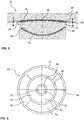
- Fig. 6 shows the in Fig. 5 indicated section along the line AA through the sliding member 20.
- a plurality of sliding disks 35 can be seen, of which the two outer sliding disks 35 have an annular shape and the inner sliding disk 35 has a circular shape.
- the first bearing member 15 can be seen, which includes the outer sliding disk 35 and chambers.
- the individual sliding discs 35 are also held by spacers 45 to each other evenly spaced. Consequently, the spacers 45 effect an internal chambering of the sliding elements 35 composed of the guide element 20 so that it can be held in the conventional manner, ie chambered, in the bearing part 15.
- the spacer 45 protruding part of the sliding disks 35 is effective as a free lateral surface AM and thus has an influence on the form factor S.
- the sliding member 20 not only from annular or circular sliding discs 35th is composed. Rather, it is conceivable that the sliding disks 35 can take any shape and form an arbitrarily shaped sliding element 20.
- Fig. 7 another embodiment of a consisting of a single sliding washer 35 sliding member 20 is shown.
- the surface of the sliding disk which is in contact as the contact surface A K in the sliding surface 30 with the second bearing part 25, can also be varied.
- a sliding disk 35 is shown, which has recesses 40, so that the contact surface A K is composed of a plurality of partial contact surfaces 50.
- the partial contact surfaces 50 are circular.
- the sum of the partial contact surfaces 50 forms the contact surface A K of the sliding disk.
- the application of a recess 40 on the sliding disk 35 causes the partial contact surfaces 50 to protrude beyond the recess.
- the free lateral surface A M of the sliding disk 35 is increased and the shape factor S influenced so that the friction of such a sliding plate is increased in comparison to one with a continuous contact surface.
- Fig. 8 shows a further embodiment of a sliding disk 35 according to the invention, in which the recesses 40 are applied in the form of straight grooves or rings on the sliding disk 35.
- the contact surface A K of the sliding disk 35 can be divided into annular surfaces and / or circles, as well as forming ring segments and / or circle segments.
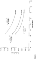
- Fig. 9 the measurement results of a series of experiments are shown, in the context of which structural sliding bearing 10 have been examined with an unlubricated circular sliding member 20 from the sliding material UHMWPE.
- the diameter of the circular sliding element was varied at a constant sliding gap height, as well as the pressure of the sliding element. It showed on the one hand that a sliding element with a diameter of 80 mm at the same pressure has a significantly higher coefficient of friction than a comparable circular sliding element with 120 mm diameter.
- the circular sliding element with a diameter of 120 mm in turn has a significantly higher coefficient of friction than a comparable circular sliding element with a diameter of 300 mm. It can also be seen that the coefficient of friction for a circular sliding element with constant diameter decreases with increasing pressure.
- the different deformation behavior of the sliding material in the center and at the edge of the contact surface A K influences the sliding resistance.
- the contact surface A K increases disproportionately to the free lateral surface A M. Accordingly, the friction coefficient decreases.
- this phenomenon can be used, for example, to increase the coefficient of friction Y for a sliding element 20 with the same contact surface A K by subdividing the contact surface A K into a plurality of partial contact surfaces 50 having the same contact area A K in total , However, since this increases the size of the free lateral surface, the coefficient of friction of the structural plain bearing increases accordingly.
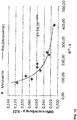
- Fig. 10 shows the relationship between the coefficient of friction and the form factor S determined in tests at a constant pressure X, where the abscissa shows the product of form factor S high 0.6 multiplied by the pressure X.
- the experiments showed that with increasing form factor, ie a growing proportion of the contact surface A K in relation to the free lateral surface A M, the coefficient of friction Y decreases.
- the experimental results show that the friction coefficient Y with sufficient accuracy as a function of the compression and the shape factor S and the pressure X for the UHMWPE under investigation can be given as follows, for example.
- Y 34 * S - 0 . 78 * X - 1 . 3 + 0 . 02
- the form factor S is dimensionless.
- the pressure X is dimensioned due to the exponent. The relationship shown therefore requires the input of the pressure in [N / mm 2 ].
- the form factor is halved by the division into four individual slices.
- the friction in the sliding surface can be increased by up to 60% without changing the material properties, or the same coefficient of friction can be achieved at a nearly double pressure as a result of a reduction of the contact surface A K.
- This allows a higher energy dissipation in building plain bearings.
- this effect can be used to substantially reduce the sliding contact area A K at the same coefficient of friction and thus to make the structural plain bearing more economical.
Landscapes
- Engineering & Computer Science (AREA)
- Structural Engineering (AREA)
- Architecture (AREA)
- Civil Engineering (AREA)
- Mechanical Engineering (AREA)
- Environmental & Geological Engineering (AREA)
- Physics & Mathematics (AREA)
- Electromagnetism (AREA)
- Mining & Mineral Resources (AREA)
- General Life Sciences & Earth Sciences (AREA)
- Life Sciences & Earth Sciences (AREA)
- Paleontology (AREA)
- General Engineering & Computer Science (AREA)
- Sliding-Contact Bearings (AREA)
- Bridges Or Land Bridges (AREA)
- Buildings Adapted To Withstand Abnormal External Influences (AREA)
- Business, Economics & Management (AREA)
- Emergency Management (AREA)
- Ink Jet (AREA)
- Vibration Prevention Devices (AREA)
- Support Of The Bearing (AREA)
Claims (21)
- Palier lisse pour la construction (10) avec au moins une première partie de palier (15) à laquelle est fixée au moins un élément de glissement (20) et une seconde partie de palier (25) agencée de manière coulissante par rapport à ladite première partie de palier, lequel élément de glissement (20) apparié à une surface de contact (AK) de l'élément de glissement (20) forme une surface de glissement (30) qui autorise des mouvements de glissement entre les deux parties de palier (15, 25),
caractérisé en ce que
la surface de contact (AK) est subdivisée en plusieurs surfaces de contact partiel et que de ce fait la forme de la surface de contact (AK) de l'élément de glissement (20) est arrangée de façon telle qu'un coefficient de frottement (Y) souhaité s'ajuste dans la surface de glissement (30), dans lequel
le coefficient de frottement (Y) dans la surface de glissement (30) est ajusté en tant que fonction d'un facteur de forme (S) prenant en considération le rapport entre la surface de contact (AK) et la surface d'enveloppe (AM) libre de l'élément de glissement (20). - Palier lisse pour la construction selon la revendication 1,
caractérisé en ce que
le coefficient de frottement (Y) souhaité dans la surface de glissement (30) est ajusté en fonction de la longueur circonférentielle et/ou de la forme en projection horizontale de la surface de contact (AK) et/ou de la hauteur de la fente de glissement (h) et/ou de l'orientation des bords de la surface de contact (AK) par rapport à l'orientation de glissement. - Palier lisse pour la construction selon la revendication 1 ou 2,
caractérisé en ce que
la taille de la surface de contact (AK) de l'élément de glissement (20) a été optimisée, de préférence minimisée, en fonction du facteur de forme (S) de manière telle que le coefficient de frottement (Y) souhaité dans la surface de glissement (30) soit atteint. - Palier lisse pour la construction selon l'une quelconque des revendications précédentes,
caractérisé en ce que
la valeur du coefficient de frottement (Y) dans la surface de glissement (30) a été maximisée en fonction du facteur de forme (S). - Palier lisse pour la construction selon l'une quelconque des revendications précédentes,
caractérisé en ce que
il est formé en tant que palier pendulaire de glissement. - Palier lisse pour la construction selon l'une quelconque des revendications précédentes,
caractérisé en ce que
la surface de contact (AK) est formée de deux, en particulier de plus de quatre, surfaces de contact partiel. - Palier lisse pour la construction selon l'une quelconque des revendications précédentes,
caractérisé en ce que
l'élément de glissement (20) présente au moins un disque de glissement (35), dans lequel la surface de contact (AK) est formée d'au moins une partie de la superficie dudit au moins un disque de glissement (35). - Palier lisse pour la construction selon l'une quelconque des revendications précédentes,
caractérisé en ce que
au moins une partie de la superficie dudit au moins un disque de glissement (35) est répartie via au moins un évidement (40) en surfaces de contact partiel (50). - Palier lisse pour la construction selon la revendication 8,
caractérisé en ce que
l'évidement (40) présente la forme d'un cercle, d'un anneau ou d'un segment de l'un des deux. - Palier lisse pour la construction selon la revendication 8 ou 9,
caractérisé en ce que
dans au moins un évidement (40) est agencée au moins une entretoise (45). - Palier lisse pour la construction selon l'une quelconque des revendications précédentes,
caractérisé en ce que
l'élément de glissement (20) présente une pluralité de disques de glissement (35). - Palier lisse pour la construction selon l'une quelconque des revendications précédentes,
caractérisé en ce que
la surface de contact (AK) et/ou au moins une surface de contact partiel (50) présente la forme d'un cercle, d'un anneau ou d'un segment de l'un des deux. - Palier lisse pour la construction selon l'une quelconque des revendications précédentes,
caractérisé en ce que
l'élément de glissement (20) et/ou au moins un disque de glissement (35) de l'élément de glissement (20) est maintenu enfermé dans la première partie de palier (15). - Palier lisse pour la construction selon l'une quelconque des revendications précédentes,
caractérisé en ce que
au moins une entretoise (45) est agencée entre deux disques de glissement (35). - Palier lisse pour la construction selon l'une quelconque des revendications précédentes,
caractérisé en ce que
l'élément de glissement (20) et/ou au moins un disque de glissement (35) est au moins partiellement constitué d'un matériau de glissement, en particulier d'un matériau de glissement thermoplastique. - Palier lisse pour la construction selon l'une quelconque des revendications précédentes,
caractérisé en ce que
l'élément de glissement (20) et/ou au moins un disque de glissement (35) est au moins partiellement constitué de PTFE, d'UHMWPE, de polyamide et/ou d'une combinaison d'au moins deux parmi de tels matériaux. - Procédé de mesure d'un palier lisse pour la construction (10) selon l'une quelconque des revendications précédentes,
caractérisé en ce que
le coefficient de frottement (Y) dans la surface de glissement (30) est ajusté en prenant en considération un facteur de forme (S), dans lequel
le coefficient de frottement (Y) dans la surface de glissement (30) est ajusté en tant que fonction d'un facteur de forme (S) prenant en considération le rapport entre la surface de contact (AK) et la surface d'enveloppe (AM) libre de l'élément de glissement (20). - Procédé de mesure d'un palier lisse pour la construction selon la revendication 17,
caractérisé en ce que
le coefficient de frottement (Y) souhaité dans la surface de glissement (30) est ajusté en fonction de la longueur circonférentielle et/ou de la forme en projection horizontale de la surface de contact (AK) et/ou de la hauteur de la fente de glissement (h) et/ou de l'orientation des bords de la surface de contact (AK) par rapport à l'orientation de glissement. - Procédé de mesure d'un palier lisse pour la construction (10) selon la revendication 17 ou 18,
caractérisé en ce que
la taille de la surface de contact (AK) de l'élément de glissement (20) est optimisée, de préférence minimisée, en fonction du facteur de forme (S) de manière telle que le coefficient de frottement (Y) souhaité dans la surface de glissement (30) soit atteint. - Procédé de mesure d'un palier lisse pour la construction (10) selon l'une quelconque des revendications 17 à 19,
caractérisé en ce que
la valeur du coefficient de frottement (Y) dans la surface de glissement (30) est maximisée en fonction du facteur de forme (S). - Procédé de mesure d'un palier lisse pour la construction (10) selon l'une quelconque des revendications 17 à 20,
caractérisé en ce que
l'appariement de matériaux dans la surface de glissement (30) est maintenu constant lors de l'optimisation.
Applications Claiming Priority (2)
| Application Number | Priority Date | Filing Date | Title |
|---|---|---|---|
| DE102013104161 | 2013-04-24 | ||
| PCT/EP2014/056255 WO2014173622A1 (fr) | 2013-04-24 | 2014-03-28 | Dispositif d'appui coulissant pour ouvrage et procédé de dimensionnement |
Publications (2)
| Publication Number | Publication Date |
|---|---|
| EP2989254A1 EP2989254A1 (fr) | 2016-03-02 |
| EP2989254B1 true EP2989254B1 (fr) | 2017-05-10 |
Family
ID=50397152
Family Applications (1)
| Application Number | Title | Priority Date | Filing Date |
|---|---|---|---|
| EP14714244.2A Active EP2989254B1 (fr) | 2013-04-24 | 2014-03-28 | Dispositif d'appui coulissant pour ouvrage et procédé de dimensionnement |
Country Status (9)
| Country | Link |
|---|---|
| EP (1) | EP2989254B1 (fr) |
| JP (1) | JP6535656B2 (fr) |
| KR (1) | KR102254214B1 (fr) |
| CA (1) | CA2909698C (fr) |
| CL (1) | CL2015003123A1 (fr) |
| ES (1) | ES2629520T3 (fr) |
| MX (1) | MX2015014736A (fr) |
| RU (1) | RU2651686C2 (fr) |
| WO (1) | WO2014173622A1 (fr) |
Cited By (2)
| Publication number | Priority date | Publication date | Assignee | Title |
|---|---|---|---|---|
| CN111519515A (zh) * | 2020-05-14 | 2020-08-11 | 株洲时代新材料科技股份有限公司 | 摩擦摆支座组装方法及产品 |
| WO2023217431A1 (fr) * | 2022-05-09 | 2023-11-16 | Maurer Engineering Gmbh | Palier lisse structural |
Families Citing this family (12)
| Publication number | Priority date | Publication date | Assignee | Title |
|---|---|---|---|---|
| CN104612041B (zh) * | 2015-01-30 | 2016-07-06 | 北京铁科首钢轨道技术股份有限公司 | 一种润滑脂自补充滑板体嵌固结构 |
| DE102015221864A1 (de) * | 2015-11-06 | 2017-05-11 | Maurer Söhne Engineering GmbH & Co. KG | Bauwerkslager |
| KR101708886B1 (ko) * | 2016-08-16 | 2017-02-22 | 주식회사 케이이테크 | 엔지니어링 플라스틱 마찰부재와 면진장치 및 그 제조방법 |
| DE102017202317B4 (de) * | 2017-02-14 | 2021-05-27 | Maurer Söhne Engineering GmbH & Co. KG | Gleitpendellager und Bemessungsverfahren für ein solches |
| US11421435B2 (en) * | 2018-12-12 | 2022-08-23 | Universidad Catolica De La Santisima Concepcion | Kinematic seismic isolation device |
| KR102027794B1 (ko) * | 2019-01-03 | 2019-10-04 | 아이컨 주식회사 | 마찰판의 이탈 및 손상이 방지된 교량 받침 |
| CN110409291A (zh) * | 2019-07-16 | 2019-11-05 | 洛阳双瑞特种装备有限公司 | 一种桥梁支座摩擦副非金属滑板分布方式 |
| JP6743263B1 (ja) * | 2019-11-26 | 2020-08-19 | 日鉄エンジニアリング株式会社 | 滑り免震装置を構成する沓とその前駆体、及びその製作方法 |
| IT202000005035A1 (it) * | 2020-03-10 | 2021-09-10 | Fip Mec S R L | Isolatore antisismico ad attrito migliorato e del tipo a pendolo scorrevole |
| CN112282093B (zh) * | 2020-09-30 | 2022-03-29 | 株洲时代新材料科技股份有限公司 | 一种摩擦摆支座 |
| IT202100005390A1 (it) * | 2021-03-09 | 2022-09-09 | Fip Mec S R L | Isolatore strutturale antisismico del tipo a pendolo scorrevole |
| ES1294730Y (es) | 2022-06-03 | 2022-12-23 | Mk4 World Wide S L | Elemento discoidal deslizable para un conjunto de apoyo estructural de ingeniería civil y mecanismo estructural |
Citations (1)
| Publication number | Priority date | Publication date | Assignee | Title |
|---|---|---|---|---|
| GB1239691A (fr) | 1968-10-10 | 1971-07-21 |
Family Cites Families (12)
| Publication number | Priority date | Publication date | Assignee | Title |
|---|---|---|---|---|
| SU783413A1 (ru) * | 1979-01-30 | 1980-11-30 | Головной Научно-Исследовательский И Проектный Институт "Крымниипроект" Госстроя Украинской Сср | Фундамент сейсмостойкого здани , сооружени |
| GB8313925D0 (en) | 1983-05-19 | 1983-06-22 | Dixon International Ltd | Structural bearings |
| SU1254117A1 (ru) * | 1984-03-07 | 1986-08-30 | Государственный Проектный И Научно-Исследовательский Институт "Казпромстройниипроект" | Фундамент сейсмостойкого здани |
| US6021992A (en) * | 1997-06-23 | 2000-02-08 | Taichung Machinery Works Co., Ltd. | Passive vibration isolating system |
| JP2000320611A (ja) * | 1999-05-12 | 2000-11-24 | Ntn Corp | すべり免震装置 |
| JP2003090013A (ja) | 2001-09-18 | 2003-03-28 | Japan Steel Works Ltd:The | 構造物の支承装置 |
| JP2003147991A (ja) * | 2001-11-09 | 2003-05-21 | Showa Electric Wire & Cable Co Ltd | すべり支承 |
| JP2007016905A (ja) * | 2005-07-07 | 2007-01-25 | Ntn Corp | すべり免震装置 |
| DE102005060375A1 (de) * | 2005-12-16 | 2007-06-21 | Steelpat Gmbh & Co. Kg | Gleitpendellager |
| FR2905465B1 (fr) * | 2006-09-06 | 2008-12-05 | Michelin Soc Tech | Procede de determination d'un coefficient d'adherence maximal d'un pneumatique |
| ITMI20071434A1 (it) * | 2007-07-17 | 2009-01-18 | Cvi Engineering S R L | Cuscinetto a strisciamento per l'ingegneria strutturale e materiali per lo stesso |
| RU92667U1 (ru) * | 2009-10-29 | 2010-03-27 | Илья Михайлович Шаферман | Опорная часть |
-
2014
- 2014-03-28 ES ES14714244.2T patent/ES2629520T3/es active Active
- 2014-03-28 EP EP14714244.2A patent/EP2989254B1/fr active Active
- 2014-03-28 JP JP2016509354A patent/JP6535656B2/ja active Active
- 2014-03-28 RU RU2015147606A patent/RU2651686C2/ru active
- 2014-03-28 WO PCT/EP2014/056255 patent/WO2014173622A1/fr active Application Filing
- 2014-03-28 CA CA2909698A patent/CA2909698C/fr active Active
- 2014-03-28 MX MX2015014736A patent/MX2015014736A/es active IP Right Grant
- 2014-03-28 KR KR1020157033237A patent/KR102254214B1/ko active IP Right Grant
-
2015
- 2015-10-22 CL CL2015003123A patent/CL2015003123A1/es unknown
Patent Citations (1)
| Publication number | Priority date | Publication date | Assignee | Title |
|---|---|---|---|---|
| GB1239691A (fr) | 1968-10-10 | 1971-07-21 |
Non-Patent Citations (3)
| Title |
|---|
| "Lager im Bauwesen - Teil 2: Gleitteile", DIN EN 1337-2:2004-07, July 2004 (2004-07-01), XP055465767 |
| "Lager im Bauwesen - Teil 7: Kalotten- und Zylinderlager mit PTFE", DEUTSCHE FASSUNG EN 1337-7:2004, August 2004 (2004-08-01), XP055465756 |
| "Lager im Bauwesen-Teil 1: Allgemeine Regelungen", DIN EN 1337-1:2001-02, February 2001 (2001-02-01), XP055465741 |
Cited By (3)
| Publication number | Priority date | Publication date | Assignee | Title |
|---|---|---|---|---|
| CN111519515A (zh) * | 2020-05-14 | 2020-08-11 | 株洲时代新材料科技股份有限公司 | 摩擦摆支座组装方法及产品 |
| CN111519515B (zh) * | 2020-05-14 | 2021-08-17 | 株洲时代新材料科技股份有限公司 | 摩擦摆支座组装方法及产品 |
| WO2023217431A1 (fr) * | 2022-05-09 | 2023-11-16 | Maurer Engineering Gmbh | Palier lisse structural |
Also Published As
| Publication number | Publication date |
|---|---|
| CL2015003123A1 (es) | 2016-06-24 |
| CA2909698A1 (fr) | 2014-10-30 |
| KR102254214B1 (ko) | 2021-05-21 |
| KR20160003742A (ko) | 2016-01-11 |
| EP2989254A1 (fr) | 2016-03-02 |
| WO2014173622A1 (fr) | 2014-10-30 |
| CA2909698C (fr) | 2021-11-16 |
| MX2015014736A (es) | 2016-06-28 |
| RU2015147606A (ru) | 2017-05-25 |
| JP2016524664A (ja) | 2016-08-18 |
| JP6535656B2 (ja) | 2019-06-26 |
| ES2629520T3 (es) | 2017-08-10 |
| RU2651686C2 (ru) | 2018-04-23 |
Similar Documents
| Publication | Publication Date | Title |
|---|---|---|
| EP2989254B1 (fr) | Dispositif d'appui coulissant pour ouvrage et procédé de dimensionnement | |
| EP3568525B1 (fr) | Palier lisse à alignement automatique et procédé de dimensionnement d'un tel palier | |
| DE602005000597T2 (de) | Treibkette und diese verwendende Antriebsvorrichtung | |
| EP3147239B1 (fr) | Courroie dentée avec rouleaux intégrés pour le support | |
| DE102011109452A1 (de) | Reiblamette mit einem Papierreibbelag, Verfahren zur Herstellung einer solchen Reiblamelle und nasslaufende Lamellenkupplung oder -bremse mit einer solchen Reiblamelle | |
| DE102007057550A1 (de) | Käfig für ein Wälzkörperlager sowie Verfahren zu dessen Herstellung | |
| DE112016003880T5 (de) | Haltering und Kegelrollenlager | |
| EP2506942B1 (fr) | Puzzle comprenant une ou plusieurs pièces pliables | |
| DE112015005188T5 (de) | Druckrollenlagerkäfig und Verfahren zur Herstellung desselben | |
| EP3328324B1 (fr) | Articulation pour un dispositif orthopédique | |
| DE112014001875T5 (de) | Lagerteil und sein Herstellungsverfahren | |
| DE3608478C2 (fr) | ||
| EP3935287B1 (fr) | Segment de cage d'un palier à roulement | |
| DE2928504C2 (de) | Dichtungsanordnung für Pumpenwellen u.dgl. | |
| DE102008026893A1 (de) | Verfahren zum Herstellen eines Käfigelements für einen Wälzlagerkäfig und Wälzlagerkäfig | |
| DE60203296T2 (de) | Kontaktlager | |
| DE102010043825A1 (de) | Klemmrollenfreilauf für eine Verstellvorrichtung in einem Kraftfahrzeug | |
| EP2530344B1 (fr) | Élément de roulement d'une articulation de trépied ainsi qu'articulation de trépied comprenant un tel élément de roulement | |
| DE102015204085B4 (de) | Gleitlager | |
| WO2023280837A1 (fr) | Appareil comprenant un dispositif de freinage magnéto-rhéologique et procédé | |
| DE102013215128A1 (de) | Wälzkörper | |
| DE2542313A1 (de) | Verfahren zum walzen metallischer rohlinge | |
| EP2591245B1 (fr) | Articulation | |
| DE102016124228B4 (de) | Fahrzeugsitz mit Federung | |
| DE2507522C2 (de) | Sicherungsring |
Legal Events
| Date | Code | Title | Description |
|---|---|---|---|
| PUAI | Public reference made under article 153(3) epc to a published international application that has entered the european phase |
Free format text: ORIGINAL CODE: 0009012 |
|
| 17P | Request for examination filed |
Effective date: 20151124 |
|
| AK | Designated contracting states |
Kind code of ref document: A1 Designated state(s): AL AT BE BG CH CY CZ DE DK EE ES FI FR GB GR HR HU IE IS IT LI LT LU LV MC MK MT NL NO PL PT RO RS SE SI SK SM TR |
|
| AX | Request for extension of the european patent |
Extension state: BA ME |
|
| DAX | Request for extension of the european patent (deleted) | ||
| GRAP | Despatch of communication of intention to grant a patent |
Free format text: ORIGINAL CODE: EPIDOSNIGR1 |
|
| STAA | Information on the status of an ep patent application or granted ep patent |
Free format text: STATUS: GRANT OF PATENT IS INTENDED |
|
| INTG | Intention to grant announced |
Effective date: 20161129 |
|
| GRAS | Grant fee paid |
Free format text: ORIGINAL CODE: EPIDOSNIGR3 |
|
| GRAA | (expected) grant |
Free format text: ORIGINAL CODE: 0009210 |
|
| STAA | Information on the status of an ep patent application or granted ep patent |
Free format text: STATUS: THE PATENT HAS BEEN GRANTED |
|
| AK | Designated contracting states |
Kind code of ref document: B1 Designated state(s): AL AT BE BG CH CY CZ DE DK EE ES FI FR GB GR HR HU IE IS IT LI LT LU LV MC MK MT NL NO PL PT RO RS SE SI SK SM TR |
|
| REG | Reference to a national code |
Ref country code: GB Ref legal event code: FG4D Free format text: NOT ENGLISH |
|
| REG | Reference to a national code |
Ref country code: AT Ref legal event code: REF Ref document number: 892455 Country of ref document: AT Kind code of ref document: T Effective date: 20170515 Ref country code: CH Ref legal event code: EP |
|
| REG | Reference to a national code |
Ref country code: CH Ref legal event code: NV Representative=s name: TROESCH SCHEIDEGGER WERNER AG, CH Ref country code: IE Ref legal event code: FG4D Free format text: LANGUAGE OF EP DOCUMENT: GERMAN |
|
| REG | Reference to a national code |
Ref country code: DE Ref legal event code: R096 Ref document number: 502014003791 Country of ref document: DE |
|
| REG | Reference to a national code |
Ref country code: ES Ref legal event code: FG2A Ref document number: 2629520 Country of ref document: ES Kind code of ref document: T3 Effective date: 20170810 |
|
| REG | Reference to a national code |
Ref country code: NL Ref legal event code: MP Effective date: 20170510 |
|
| REG | Reference to a national code |
Ref country code: LT Ref legal event code: MG4D |
|
| PG25 | Lapsed in a contracting state [announced via postgrant information from national office to epo] |
Ref country code: HR Free format text: LAPSE BECAUSE OF FAILURE TO SUBMIT A TRANSLATION OF THE DESCRIPTION OR TO PAY THE FEE WITHIN THE PRESCRIBED TIME-LIMIT Effective date: 20170510 Ref country code: FI Free format text: LAPSE BECAUSE OF FAILURE TO SUBMIT A TRANSLATION OF THE DESCRIPTION OR TO PAY THE FEE WITHIN THE PRESCRIBED TIME-LIMIT Effective date: 20170510 Ref country code: LT Free format text: LAPSE BECAUSE OF FAILURE TO SUBMIT A TRANSLATION OF THE DESCRIPTION OR TO PAY THE FEE WITHIN THE PRESCRIBED TIME-LIMIT Effective date: 20170510 Ref country code: NO Free format text: LAPSE BECAUSE OF FAILURE TO SUBMIT A TRANSLATION OF THE DESCRIPTION OR TO PAY THE FEE WITHIN THE PRESCRIBED TIME-LIMIT Effective date: 20170810 |
|
| PG25 | Lapsed in a contracting state [announced via postgrant information from national office to epo] |
Ref country code: RS Free format text: LAPSE BECAUSE OF FAILURE TO SUBMIT A TRANSLATION OF THE DESCRIPTION OR TO PAY THE FEE WITHIN THE PRESCRIBED TIME-LIMIT Effective date: 20170510 Ref country code: PL Free format text: LAPSE BECAUSE OF FAILURE TO SUBMIT A TRANSLATION OF THE DESCRIPTION OR TO PAY THE FEE WITHIN THE PRESCRIBED TIME-LIMIT Effective date: 20170510 Ref country code: BG Free format text: LAPSE BECAUSE OF FAILURE TO SUBMIT A TRANSLATION OF THE DESCRIPTION OR TO PAY THE FEE WITHIN THE PRESCRIBED TIME-LIMIT Effective date: 20170810 Ref country code: SE Free format text: LAPSE BECAUSE OF FAILURE TO SUBMIT A TRANSLATION OF THE DESCRIPTION OR TO PAY THE FEE WITHIN THE PRESCRIBED TIME-LIMIT Effective date: 20170510 Ref country code: IS Free format text: LAPSE BECAUSE OF FAILURE TO SUBMIT A TRANSLATION OF THE DESCRIPTION OR TO PAY THE FEE WITHIN THE PRESCRIBED TIME-LIMIT Effective date: 20170910 Ref country code: LV Free format text: LAPSE BECAUSE OF FAILURE TO SUBMIT A TRANSLATION OF THE DESCRIPTION OR TO PAY THE FEE WITHIN THE PRESCRIBED TIME-LIMIT Effective date: 20170510 Ref country code: NL Free format text: LAPSE BECAUSE OF FAILURE TO SUBMIT A TRANSLATION OF THE DESCRIPTION OR TO PAY THE FEE WITHIN THE PRESCRIBED TIME-LIMIT Effective date: 20170510 |
|
| PG25 | Lapsed in a contracting state [announced via postgrant information from national office to epo] |
Ref country code: EE Free format text: LAPSE BECAUSE OF FAILURE TO SUBMIT A TRANSLATION OF THE DESCRIPTION OR TO PAY THE FEE WITHIN THE PRESCRIBED TIME-LIMIT Effective date: 20170510 Ref country code: CZ Free format text: LAPSE BECAUSE OF FAILURE TO SUBMIT A TRANSLATION OF THE DESCRIPTION OR TO PAY THE FEE WITHIN THE PRESCRIBED TIME-LIMIT Effective date: 20170510 Ref country code: RO Free format text: LAPSE BECAUSE OF FAILURE TO SUBMIT A TRANSLATION OF THE DESCRIPTION OR TO PAY THE FEE WITHIN THE PRESCRIBED TIME-LIMIT Effective date: 20170510 Ref country code: SK Free format text: LAPSE BECAUSE OF FAILURE TO SUBMIT A TRANSLATION OF THE DESCRIPTION OR TO PAY THE FEE WITHIN THE PRESCRIBED TIME-LIMIT Effective date: 20170510 Ref country code: DK Free format text: LAPSE BECAUSE OF FAILURE TO SUBMIT A TRANSLATION OF THE DESCRIPTION OR TO PAY THE FEE WITHIN THE PRESCRIBED TIME-LIMIT Effective date: 20170510 |
|
| REG | Reference to a national code |
Ref country code: GR Ref legal event code: EP Ref document number: 20170402075 Country of ref document: GR Effective date: 20180119 |
|
| REG | Reference to a national code |
Ref country code: DE Ref legal event code: R026 Ref document number: 502014003791 Country of ref document: DE |
|
| PLBI | Opposition filed |
Free format text: ORIGINAL CODE: 0009260 |
|
| PG25 | Lapsed in a contracting state [announced via postgrant information from national office to epo] |
Ref country code: SM Free format text: LAPSE BECAUSE OF FAILURE TO SUBMIT A TRANSLATION OF THE DESCRIPTION OR TO PAY THE FEE WITHIN THE PRESCRIBED TIME-LIMIT Effective date: 20170510 |
|
| PLAX | Notice of opposition and request to file observation + time limit sent |
Free format text: ORIGINAL CODE: EPIDOSNOBS2 |
|
| PLAN | Information deleted related to communication of a notice of opposition and request to file observations + time limit |
Free format text: ORIGINAL CODE: EPIDOSDOBS2 |
|
| 26 | Opposition filed |
Opponent name: MAGEBA S.A. Effective date: 20180210 |
|
| REG | Reference to a national code |
Ref country code: FR Ref legal event code: PLFP Year of fee payment: 5 |
|
| PG25 | Lapsed in a contracting state [announced via postgrant information from national office to epo] |
Ref country code: SI Free format text: LAPSE BECAUSE OF FAILURE TO SUBMIT A TRANSLATION OF THE DESCRIPTION OR TO PAY THE FEE WITHIN THE PRESCRIBED TIME-LIMIT Effective date: 20170510 |
|
| PG25 | Lapsed in a contracting state [announced via postgrant information from national office to epo] |
Ref country code: MT Free format text: LAPSE BECAUSE OF FAILURE TO SUBMIT A TRANSLATION OF THE DESCRIPTION OR TO PAY THE FEE WITHIN THE PRESCRIBED TIME-LIMIT Effective date: 20170510 |
|
| GBPC | Gb: european patent ceased through non-payment of renewal fee |
Effective date: 20180328 |
|
| PG25 | Lapsed in a contracting state [announced via postgrant information from national office to epo] |
Ref country code: MC Free format text: LAPSE BECAUSE OF FAILURE TO SUBMIT A TRANSLATION OF THE DESCRIPTION OR TO PAY THE FEE WITHIN THE PRESCRIBED TIME-LIMIT Effective date: 20170510 |
|
| REG | Reference to a national code |
Ref country code: BE Ref legal event code: MM Effective date: 20180331 |
|
| REG | Reference to a national code |
Ref country code: IE Ref legal event code: MM4A |
|
| PG25 | Lapsed in a contracting state [announced via postgrant information from national office to epo] |
Ref country code: LU Free format text: LAPSE BECAUSE OF NON-PAYMENT OF DUE FEES Effective date: 20180328 |
|
| PG25 | Lapsed in a contracting state [announced via postgrant information from national office to epo] |
Ref country code: IE Free format text: LAPSE BECAUSE OF NON-PAYMENT OF DUE FEES Effective date: 20180328 |
|
| PG25 | Lapsed in a contracting state [announced via postgrant information from national office to epo] |
Ref country code: GB Free format text: LAPSE BECAUSE OF NON-PAYMENT OF DUE FEES Effective date: 20180328 Ref country code: BE Free format text: LAPSE BECAUSE OF NON-PAYMENT OF DUE FEES Effective date: 20180331 |
|
| APBM | Appeal reference recorded |
Free format text: ORIGINAL CODE: EPIDOSNREFNO |
|
| APAH | Appeal reference modified |
Free format text: ORIGINAL CODE: EPIDOSCREFNO |
|
| PG25 | Lapsed in a contracting state [announced via postgrant information from national office to epo] |
Ref country code: PT Free format text: LAPSE BECAUSE OF FAILURE TO SUBMIT A TRANSLATION OF THE DESCRIPTION OR TO PAY THE FEE WITHIN THE PRESCRIBED TIME-LIMIT Effective date: 20170510 |
|
| PG25 | Lapsed in a contracting state [announced via postgrant information from national office to epo] |
Ref country code: CY Free format text: LAPSE BECAUSE OF FAILURE TO SUBMIT A TRANSLATION OF THE DESCRIPTION OR TO PAY THE FEE WITHIN THE PRESCRIBED TIME-LIMIT Effective date: 20170510 Ref country code: MK Free format text: LAPSE BECAUSE OF NON-PAYMENT OF DUE FEES Effective date: 20170510 Ref country code: HU Free format text: LAPSE BECAUSE OF FAILURE TO SUBMIT A TRANSLATION OF THE DESCRIPTION OR TO PAY THE FEE WITHIN THE PRESCRIBED TIME-LIMIT; INVALID AB INITIO Effective date: 20140328 |
|
| PG25 | Lapsed in a contracting state [announced via postgrant information from national office to epo] |
Ref country code: AL Free format text: LAPSE BECAUSE OF FAILURE TO SUBMIT A TRANSLATION OF THE DESCRIPTION OR TO PAY THE FEE WITHIN THE PRESCRIBED TIME-LIMIT Effective date: 20170510 |
|
| REG | Reference to a national code |
Ref country code: AT Ref legal event code: MM01 Ref document number: 892455 Country of ref document: AT Kind code of ref document: T Effective date: 20190328 |
|
| PG25 | Lapsed in a contracting state [announced via postgrant information from national office to epo] |
Ref country code: AT Free format text: LAPSE BECAUSE OF NON-PAYMENT OF DUE FEES Effective date: 20190328 |
|
| PLBG | Opposition deemed not to have been filed |
Free format text: ORIGINAL CODE: 0009274 |
|
| 26D | Opposition deemed not to have been filed |
Opponent name: MAGEBA S.A. Effective date: 20210707 |
|
| PGFP | Annual fee paid to national office [announced via postgrant information from national office to epo] |
Ref country code: FR Payment date: 20230320 Year of fee payment: 10 |
|
| PGFP | Annual fee paid to national office [announced via postgrant information from national office to epo] |
Ref country code: TR Payment date: 20230323 Year of fee payment: 10 |
|
| PGFP | Annual fee paid to national office [announced via postgrant information from national office to epo] |
Ref country code: IT Payment date: 20230331 Year of fee payment: 10 Ref country code: ES Payment date: 20230414 Year of fee payment: 10 Ref country code: CH Payment date: 20230402 Year of fee payment: 10 |
|
| PGFP | Annual fee paid to national office [announced via postgrant information from national office to epo] |
Ref country code: GR Payment date: 20240319 Year of fee payment: 11 |
|
| PGFP | Annual fee paid to national office [announced via postgrant information from national office to epo] |
Ref country code: DE Payment date: 20240321 Year of fee payment: 11 |