EP4366940B1 - Reifenentladeeinheit zum entladen eines reifenrohlings - Google Patents
Reifenentladeeinheit zum entladen eines reifenrohlings Download PDFInfo
- Publication number
- EP4366940B1 EP4366940B1 EP22735638.3A EP22735638A EP4366940B1 EP 4366940 B1 EP4366940 B1 EP 4366940B1 EP 22735638 A EP22735638 A EP 22735638A EP 4366940 B1 EP4366940 B1 EP 4366940B1
- Authority
- EP
- European Patent Office
- Prior art keywords
- tire
- lateral
- unloading unit
- boundary
- arm body
- Prior art date
- Legal status (The legal status is an assumption and is not a legal conclusion. Google has not performed a legal analysis and makes no representation as to the accuracy of the status listed.)
- Active
Links
Images


Classifications
-
- B—PERFORMING OPERATIONS; TRANSPORTING
- B29—WORKING OF PLASTICS; WORKING OF SUBSTANCES IN A PLASTIC STATE IN GENERAL
- B29D—PRODUCING PARTICULAR ARTICLES FROM PLASTICS OR FROM SUBSTANCES IN A PLASTIC STATE
- B29D30/00—Producing pneumatic or solid tyres or parts thereof
- B29D30/06—Pneumatic tyres or parts thereof (e.g. produced by casting, moulding, compression moulding, injection moulding, centrifugal casting)
- B29D30/08—Building tyres
- B29D30/20—Building tyres by the flat-tyre method, i.e. building on cylindrical drums
-
- B—PERFORMING OPERATIONS; TRANSPORTING
- B29—WORKING OF PLASTICS; WORKING OF SUBSTANCES IN A PLASTIC STATE IN GENERAL
- B29D—PRODUCING PARTICULAR ARTICLES FROM PLASTICS OR FROM SUBSTANCES IN A PLASTIC STATE
- B29D30/00—Producing pneumatic or solid tyres or parts thereof
- B29D30/0016—Handling tyres or parts thereof, e.g. supplying, storing, conveying
-
- B—PERFORMING OPERATIONS; TRANSPORTING
- B29—WORKING OF PLASTICS; WORKING OF SUBSTANCES IN A PLASTIC STATE IN GENERAL
- B29D—PRODUCING PARTICULAR ARTICLES FROM PLASTICS OR FROM SUBSTANCES IN A PLASTIC STATE
- B29D30/00—Producing pneumatic or solid tyres or parts thereof
- B29D30/06—Pneumatic tyres or parts thereof (e.g. produced by casting, moulding, compression moulding, injection moulding, centrifugal casting)
- B29D30/08—Building tyres
- B29D30/20—Building tyres by the flat-tyre method, i.e. building on cylindrical drums
- B29D30/24—Drums
- B29D30/26—Accessories or details, e.g. membranes, transfer rings
- B29D30/2607—Devices for transferring annular tyre components during the building-up stage, e.g. from the first stage to the second stage building drum
-
- B—PERFORMING OPERATIONS; TRANSPORTING
- B29—WORKING OF PLASTICS; WORKING OF SUBSTANCES IN A PLASTIC STATE IN GENERAL
- B29D—PRODUCING PARTICULAR ARTICLES FROM PLASTICS OR FROM SUBSTANCES IN A PLASTIC STATE
- B29D30/00—Producing pneumatic or solid tyres or parts thereof
- B29D30/0016—Handling tyres or parts thereof, e.g. supplying, storing, conveying
- B29D2030/0022—Handling green tyres, e.g. transferring or storing between tyre manufacturing steps
Definitions
- the invention relates to a tire unloading unit for unloading a green or unvulcanized tire.
- the green tire is built on a tire building drum and is removed from said tire building drum once the tire building has been completed with the use of a tire unloading unit.
- the known tire unloading unit is provided with two lower arms and one upper arm which are insertable in the space between a transfer ring and the tire building drum such that the green tire may already be transferred to the tire unloading unit prior to or during retraction of the tire building drum.
- the upper arm is movable towards the two lower arms to stabilize the green tire in the tire unloading unit. Subsequently, the upper arm is moved away from the two lower arms to allow for weighing of the green tire and/or removal of the green tire from the tire unloading unit by a robot.
- WO2009131446A1 discloses a method for manufacturing a green tire using a building drum and a transfer device.
- EP2463085A1 discloses a tire support device comprising a support member having an inner surface and an outer surface and a support flange mounted to the support member.
- a disadvantage of the aforementioned removal of the green tire from the tire building drum and transfer to the tire unloading unit is that the steps are performed relatively quickly to reduce the cycle time of the tire building.
- the transfer ring, the tire building drum may unintentionally exert forces onto the green tire that may destabilize said green tire.
- the upper arm has to be pressed down relatively hard onto the green tire to prevent that the green tire falls over within the tire unloading unit.
- the forceful application of the upper arm on the green tire may cause imprints. It may even deform the general shape of the green tire.
- the green tire may collapse slightly to a level below the reach of the upper arm, causing it to fall over despite the earlier attempts to stabilize it.
- the invention provides a tire unloading unit for unloading a green tire, wherein the green tire has an externally facing circumferential tread surface extending around a tire axis, wherein the tire unloading unit comprises a base and a support member for supporting the green tire relative to the base at the externally facing circumferential tread surface from below and an upper arm projecting from the base for stabilizing the green tire at the externally facing circumferential tread surface from above, , wherein the upper arm comprises an arm body projecting in the lateral direction from the base and movable relative to the base in a clamping direction between a standby position and a hold position closer to the support member in the clamping direction than the standby position, wherein the upper arm comprises a first lateral boundary member and a second lateral boundary member, supported by said arm body, which are positionable on opposite sides of the green tire in a lateral direction at least partially alongside said green tire, wherein the upper arm comprises a plurality of intermediate boundary members located side-by-side in the lateral direction on the arm body
- the upper arm In the standby position, the upper arm can be moved over the green tire in the lateral direction to correctly align the lateral boundary members at the respective sides of the green tire, before moving said upper arm down into the hold position in which the lateral boundary members extend alongside the green tire at said respective sides.
- the upper arm when used in combination with a transfer ring, the upper arm, in the standby position, is positioned relative to the transfer ring and the tire building drum such that the upper arm, including the lateral boundary members, fits in the space between said transfer ring and the tire building drum.
- the intermediate boundary members can be used to contact the green tire in the area between the lateral boundary members, to more securely hold the green tire. Moreover, the intermediate boundary members can closely follow or adapt to the contour of the green tire and remain in contact with said contour even when the green tire collapses slightly over time.
- the set of the lateral boundary members and the intermediate boundary members can be used to reliably stabilize green tires of different shapes and sizes.
- the width of the green tire is smaller than the distance between the lateral boundary members, the intermediate boundary members closest to the respective sides of the green tire can take over the functionality of lateral boundary member from the outermost lateral boundary members. Hence, any width of green tire can be reliably stabilized.
- the lateral boundary members and the intermediate boundary members can be individually positioned to follow the cross-sectional contour of the externally facing circumferential tread surface of the green tire as close and/or as accurately as possible.
- the lateral boundary members and the group of intermediate boundary members that are located at the transition from the externally facing circumferential tread surface to the sidewall, also known as the 'shoulder' can be positioned progressively in the clamping direction to closely follow the curvature of said shoulder. In this way, the green tire is not only stopped from falling over, its position on the support member can be secured more reliably, for example by also preventing minimal movements of the green tire relative to the support member.
- one or more intermediate boundary members of the plurality of intermediate boundary members are pivotable with respect to a normal plane perpendicular to the lateral direction from a first state parallel to said normal plane to a second state at an oblique angle to said normal plane.
- the normal plane extends vertically or substantially vertically.
- the tire unloading unit further comprises a first axial fixation member and a second axial fixation member immovably arranged on the upper arm in the lateral direction on opposite sides of a group comprising the first lateral boundary member, the second lateral boundary member and the intermediate boundary members.
- the tire unloading unit further comprises a first axial fixation member and a second axial fixation member arranged on the upper arm in the lateral direction on opposite sides of a group comprising the first lateral boundary member, the second lateral boundary member and the intermediate boundary members, wherein at least one of the first axial fixation member and the second axial fixation member is movable in the lateral direction away from the other of the first axial fixation member and the second axial fixation member.
- This may provide some freedom of movement to the group of boundary members in the lateral direction in response to unexpected errors during the removal of the green tire from the tire building drum.
- the at least one of the first axial fixation member and the second axial fixation member is biased to move towards the other of the first axial fixation member and the second axial fixation member.
- the group of boundary members can be kept in position on the arm body as if the at least one axial fixation member is fixed, until a force exerted onto said at least one axial fixation member exceeds a biasing force.
- each boundary member of the group is pivotable with respect to a normal plane perpendicular to the lateral direction from a first state parallel to said normal plane to a second state at an oblique angle to said normal plane.
- the first axial fixation member and the second axial fixation member are provided with a first chamfered surface and a second chamfered surface, respectively, facing the group to provide the first lateral boundary member and the second lateral boundary member, respectively, freedom to move from the first state into the second state.
- the boundary members are allowed to pivot.
- first chamfered surface and the second chamfered surface extend point-symmetrically with respect to each other. In this manner, the chamfered surfaces provide the space for the boundary members to pivot.
- first lateral boundary member, the second lateral boundary member and the plurality of intermediate boundary members each comprise a boundary body with a through opening in the lateral direction for receiving the arm body, wherein the arm body has an arm body height in the clamping direction and wherein the through opening has an opening height in the clamping direction that is greater than the arm body height, wherein the boundary body is slidable over the arm body in the clamping direction within a range defined by the difference between the arm body height and the opening height.
- the boundary body can thus be slid up and down in the clamping direction around the arm body in response to a contact of the respective boundary member with the green tire.
- the arm body is provided with two oppositely facing guide surfaces extending parallel to the clamping direction, wherein the through opening has two mutually facing sliding surfaces extending parallel to the clamping direction for sliding along the respective guide surfaces of the arm body.
- the interaction between guide surfaces and the slide surfaces can prevent that the boundary body moves relative to the arm body in any other direction other than the clamping direction.
- rotation of the boundary body about the arm body can be prevented.
- the orientation of the boundary body with respect to the arm body can be maintained.
- the arm body has a rectangular cross section perpendicular to the lateral direction.
- the boundary body can slide along the parallel sides of said rectangular cross section.
- first lateral boundary member, the second lateral boundary member and the plurality of intermediate boundary members each comprise a boundary body that is slidably received in a corresponding through hole in the arm body to be movable in the clamping direction relative to said arm body.
- the boundary body can thus be slid up and down in the clamping direction through the arm body in response to a contact of the respective boundary member with the green tire.
- first lateral boundary member, the second lateral boundary member and the plurality of intermediate boundary members are movable in the clamping direction relative to the arm body under the influence of gravity.
- the boundary members are free to move downwards in the clamping direction when the distance between the shaft and the green tire at the location of the respective boundary member allows for said downward movement. Consequently, no separate drive is required to actively push the boundary members down.
- the support member comprises a first lower arm projecting from the base in the lateral direction for supporting the green tire at the externally facing circumferential tread surface from below.
- the first lower arm can project from the base and extend underneath the green tire to support said green tire from below in at least one support position.
- a single lower arm can be sufficiently lean to fit into tight spaces, i.e. in the space left between the drum and the transfer ring.
- the support member further comprises a second lower arm projecting from the base in the lateral direction for together with the first lower arm supporting the green tire at the externally facing circumferential tread surface from below in two circumferentially spaced apart support positions.
- the two lower arms can provide a more stable two-point support for the green tire.
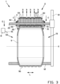
- Figures 1-3 show a tire unloading unit 1 for unloading a green or unvulcanized tire 9 according to a first exemplary embodiment of the invention.
- the green tire 9 is built on a tire building drum and is removed from said tire building drum by the tire unloading unit 1 once the tire building has been completed.
- the tire unloading unit 1 may already be moved into position around the tire building drum when the tire building process is still operational or being completed, e.g. when a transfer ring for transferring one or more tire components to the tire building drum is still in a position around the drum.
- the tire building drum and/or the transfer ring can subsequently be retracted and/or moved away.
- the tire building drum may remain in place and the tire unloading unit 1 can be retracted and/or moved away.
- the movements of the tire building drum and/or the tire unloading unit 9 are preferably controlled by a linear drive, for example a servo motor.
- the green tire 9 - once stabilized - can be analyzed, inspected, measured, weighed and/or tagged in said tire unloading unit 1, prior to final unloading.
- the green tire 9 has an externally facing circumferential tread surface 90, i.e. the circumferential surface that faces radially outwards.
- the tread surface 90 extends circumferentially and/or concentrically about a tire axis X.
- the tire unloading unit 1 is arranged for holding the green tire 9 in an upright orientation, i.e. with the tire axis X extending horizontally or substantially horizontally.
- the green tire 9 further has a first side S1 and a second side S2, opposite to the first side S1, in a lateral direction L parallel to said tire axis X.
- the tire unloading unit 1 comprises a frame or a base 10 that represents the fixed world.
- the base 10 may be placed on the ground, i.e. the factory floor.
- the tire unloading unit 1 further comprises a support member 11, 12 comprising a first lower arm 11 and a second lower arm 12 that project from the base 10 in the lateral direction L for supporting the green tire 9 at the externally facing circumferential tread surface 90 from below in two circumferentially spaced apart support positions.
- the tire unloading unit 1 may be provided with a single lower arm, table, platform or another suitable supporting element that has a width or geometry suitable to reliably support the green tire 9 from below.
- the support member 11, 12 may be arranged so as to be movable along the base 10 into contact with the green tire 9 at the tire building drum.
- the tire unloading unit 1 further comprises an upper arm 2 projecting from the base 10 for stabilizing the green tire 9 at the externally facing circumferential tread surface 90 from above.
- the upper arm 2 comprises an arm body 20 projecting in the lateral direction L from the base to stabilize the green tire 9 at the tread surface 90 from above.
- the arm body 20 is shaped like a shaft, rod or beam.
- the arm body 20 is movable along or relative to the base 10 in a clamping direction C between a standby position, as shown in figure 1 , and a hold position, as shown in figure 2 , closer to the first lower arm 11 in the clamping direction C than the standby position.
- the clamping direction C is vertical or substantially vertical.
- the upper arm 2 may cooperate with the support member 11, 12 to clamp the green tire 9 from opposite sides along the base 10 when the green tire 9 is still on the tire building drum.
- the tire unloading unit 1 comprises a tilt member 15 between the base 10 and the arm body 20 to position the arm body 20 relative to the base 10.
- the tilt member 15 is hingably connected to the base 10 in order to tilt about a tilt axis T parallel to the tire axis X. Consequently, the arm body 20 has some freedom of movement about the tilt axis T to move into towards the green tire 9 from above under the influence of gravity G.
- the upper arm 2 comprises a set of boundary members 31-33, including a first lateral boundary member 31, a second lateral boundary member 32 and a plurality of intermediate boundary members 33.
- the lateral boundary members 31, 32 are positionable alongside said green tire 9 on the opposite sides S1, S2 of the green tire 9 in the lateral direction L.
- the plurality of intermediate boundary members 33 are located or arranged side-by-side in the lateral direction L on the arm body 20 between the first lateral boundary member 31 and the second lateral boundary member 32.
- the lateral boundary members 31, 32 and the intermediate boundary members 33 are supported by said arm body 20, projecting downwards from said arm body 20 in the clamping direction C.
- each boundary member 31-33 of the group comprising the lateral boundary members 31, 32 and the intermediate boundary members 33 is individually and/or independently movable in the clamping direction C relative to the other boundary members 31-33 of the group, and with respect to the arm body 20.
- the tire unloading unit 1 is provided with a first axial fixation member 51 and a second axial fixation member 52 which are immovably arranged on the upper arm 2 in the lateral direction L.
- the fixation members 51, 52 are located on opposite sides of a group formed by the boundary members 31-33, to fix said group in place on the upper arm 2 relative to the lateral direction L.
- each boundary member 31-33 comprises a boundary body 4 with a through opening 40 in the lateral direction for receiving the arm body 20.
- the boundary body 4 is planar or platelike and preferably has a rectangular or substantially rectangular cross section, as shown in figures 1 and 2 .
- the boundary body 4 may have a different cross-sectional shape, i.e. a round or disc-shape.
- the arm body 20 has an arm body height H1 in the clamping direction C.
- the through opening 40 has an opening height H2 in the clamping direction C that is greater than the arm body height H1.
- the boundary body 4 is slidable over the arm body 20 in the clamping direction C within a stroke or a range R defined by the difference between the arm body height H1 and the opening height H2.
- the arm body 20 is provided with two oppositely facing guide surfaces 21, 22 extending parallel to the clamping direction C.
- the through opening 40 has two mutually facing sliding surfaces 41, 42 complimentary to the guide surfaces 21, 22 and extending parallel to the clamping direction C for sliding along said respective guide surfaces 21, 22 of the arm body 20.
- the arm body 20 has a rectangular or square cross section, or a substantially rectangular or square cross section.
- the through opening 40 has a rectangular inner contour.
- the boundary members 31-33 are movable in the clamping direction C relative to the arm body 20 under the influence of gravity G.
- the boundary members 31-33 start out in the standby position of figure 1 being lowered into their lowermost position on the arm body 20, i.e. at the end of the range R.
- the arm body 20 is then lowered towards the green tire 9 and, upon contact with the green tire 9, the boundary members 31-33 that come into contact with the green tire 9 are pushed upwards in an upward direction D opposite to the clamping direction C.
- each boundary member 31-33 either contacts the tread surface 90 of the green tire 9 or remains at the end of the range R relative to the arm body 20 alongside the green tire 9 in the lateral direction L.
- the group of boundary members 31-33 is able to closely and/or accurately follow the contour or cross-sectional shape of the green tire 9, in particular the contour of the tread surface 90, thereby limiting the freedom of movement of the green tire 9 in the tire unloading unit 1 and thus effectively stabilizing the green tire 9. More specifically, the boundary members 31-33 extending at, near, around and/or alongside the shoulders of the green tire 9, i.e. at the transition from the tread surface 90 to the sides S1, S2, can stop the green tire 9 from falling over in the tire unloading unit 1.
- Figure 4 shows an alternative tire unloading unit 101 according to a second exemplary embodiment of the invention, that differs from the further alternative tire unloading unit 1 according to the first exemplary embodiment of the invention in that the first lateral boundary member 31, the second lateral boundary member 32 and the intermediate boundary members 33 are pivotable with respect to a normal plane V perpendicular to the lateral direction L from a first state parallel to said normal plane V (similar to figure 3 ) to a second state at an oblique angle F to said normal plane V.
- the normal plane V extends vertically or substantially vertically.
- the alternative tire unloading unit 101 further comprises a first axial fixation member 151 and a second axial fixation member 152 arranged on the upper arm 120 in the lateral direction L on opposite sides of a group comprising the first lateral boundary member 31, the second lateral boundary member 32 and the intermediate boundary members 33.
- the axial fixation members 151, 152 differ from the aforementioned axial fixation members 51, 52 in that the second axial fixation member 152 is movable in the lateral direction L away from the first axial fixation member 151.
- the second axial fixation member 152 may provide some freedom of movement to the group of boundary members 31-33 in the lateral direction L, for example to allow for the aforementioned pivoting of the boundary members 31-33 in response to a delay in the release of the green tire 9 from the tire building drum 8.
- the alternative tire unloading unit 101 comprises a biasing element 153, for example a spring, for biasing the second axial fixation member 152 towards the first axial fixation member 151.
- a biasing element 153 for example a spring
- the group of boundary members 31-33 can be kept in position on the arm body 120 as if the second axial fixation member 152 is fixed, until a force exerted onto said second axial fixation member 152 exceeds a biasing force exerted by the biasing element 153 onto said second axial fixation member 152.
- first axial fixation member 151 and the second axial fixation member 152 are provided with a first chamfered surface 155 and a second chamfered surface 156, respectively, facing the group of boundary members 31-33 to provide the first lateral boundary member 31 and the second lateral boundary member 32, respectively, freedom to move from the first state into the second state.
- the chamfered surfaces 155, 156 are located on opposite sides of a horizontal midplane E extending through the heart of the arm body 120.
- the first chamfered surface 155 and the second chamfered surface 156 extend point-symmetrically with respect to each other, in particular on opposite sides of said horizontal midplane E. More in particular, the chamfered surfaces 155, 156 extend parallel or mutually parallel, or at inclined in the same direction.
- each axial fixation member 151, 152 may be provided with two chamfered surfaces forming a triangular tip portion (not shown) symmetrical to the horizontal midplane E to allow for pivoting of the group of boundary members 31-33 to both sides of the normal plane V.
- Each of the aforementioned tire unloading units 1, 101 may be used in a method for unloading or removing the green tire 9 from a tire building drum, using the respective upper arms 2, 102 in the manner as previously described.
- spindle-and-nut mechanism as shown in figure 6 may be replaced by any other suitable linear drive mechanism, i.e. one or more servo-motors, a gear rack, a timing belt or the like.
- lateral boundary members are kept close to or parallel to the arm body during the interaction of the tire unloading unit with the transfer ring and/or the tire building drum to minimize the dimensions of upper arm, given the limited space available between the transfer ring and the tire building drum.
- Such lateral boundary members may be deployed, extended and/or folded outwards after the tire building drum and/or the transfer ring have cleared and/or moved away from the tire unloading unit.
- a marking device M may be provided at or near the tire unloading unit 1 for marking the green tire 9 when manufacturing of said green tire has been completed, i.e. just prior to, during or after unloading.
- the marking device M produces a sticker 91 with information related to the completed green tire 9, e.g. a serial number, a bar code, a QR code or the like.
- the marking device M may be a printer that prints a marking directly on the green tire 9.
- the marking device M may be configured for creating the marking directly on or in the material of the green tire 9, i.e . by engraving.
- such a marking is provided prematurely on a part of the green tire or an incomplete green tire, for example to the side wall. With further manufacturing steps still to be performed, there is a risk that the premature marking is lost, for example when it is applied to a part of the green tire that is cut away.
- the present invention provides a method in which the marking 91 is applied to the green tire 9 when the construction of said green tire 9 has already been completed, in particular when said green tire 9 is held in a completed state in the tire unloading unit 1 or just after unloading.
Landscapes
- Engineering & Computer Science (AREA)
- Mechanical Engineering (AREA)
- Tyre Moulding (AREA)
Claims (15)
- Reifenentladeeinheit (1, 101) zum Entladen eines Reifenrohlings (9), wobei der Reifenrohling (9) eine nach außen gewandte umlaufende Laufflächenoberfläche (90) aufweist, die sich um eine Reifenachse (X) erstreckt, wobei die Reifenentladeeinheit (1, 101) eine Basis (10) und ein Tragelement zum Tragen des Reifenrohlings (9) relativ zur Basis (10) von unten an der nach außen gewandten umlaufenden Laufflächenoberfläche (90) und einen von der Basis (10) hervorstehenden oberen Arm (2, 102) zum Stabilisieren des Reifenrohlings (9) von oben an der nach außen gewandten umlaufenden Laufflächenoberfläche (90) umfasst, wobei der obere Arm (2, 102) einen Armkörper (20) umfasst, der in der seitlichen Richtung (L) von der Basis (10) hervorsteht und relativ zur Basis (10) in einer Einspannrichtung (C) zwischen einer Bereitschaftsposition und einer Halteposition bewegbar ist, die näher an dem Tragelement in der Einspannrichtung (C) als die Bereitschaftsposition ist, dadurch gekennzeichnet, dass der obere Arm (2, 102) ein erstes seitliches Begrenzungselement (31) und ein zweites seitliches Begrenzungselement (32) umfasst, die von dem Armkörper (20) getragen werden und auf entgegengesetzten Seiten des Reifenrohlings (9) in einer seitlichen Richtung (L) zumindest teilweise längs des Reifenrohlings (9) positioniert werden können, wobei der obere Arm (2, 102) eine Vielzahl von Zwischenbegrenzungselementen (33) umfasst, die nebeneinander in der seitlichen Richtung (L) auf dem Armkörper (20) zwischen dem ersten seitlichen Begrenzungselement (31) und dem zweiten seitlichen Begrenzungselement (32) angeordnet sind, wobei das erste seitliche Begrenzungselement (31), das zweite seitliche Begrenzungselement (32) und die Vielzahl von Zwischenbegrenzungselementen (33) einzeln in der Einspannrichtung (C) relativ zum Armkörper (20) und relativ zueinander bewegbar sind.
- Reifenentladeeinheit (101) nach Anspruch 1, wobei eines oder mehrere Zwischenbegrenzungselemente (33) der Vielzahl von Zwischenbegrenzungselementen (33) gegenüber einer zur seitlichen Richtung (L) perpendikularen Normalebene (V) aus einem zu der Normalebene (V) parallelen ersten Zustand in einen zweiten Zustand mit einem schiefen Winkel (F) zu der Normalebene (V) drehbar sind,
vorzugsweise wobei sich die Normalebene (V) senkrecht oder im Wesentlichen senkrecht erstreckt. - Reifenentladeeinheit (101) nach Anspruch 1 oder 2, wobei die Reifenentladeeinheit (101) ferner ein erstes Axialbefestigungselement (151) und ein zweites Axialbefestigungselement (152) umfasst, die unbeweglich auf dem oberen Arm (102) in der seitlichen Richtung (L) auf entgegengesetzten Seiten einer Gruppe angeordnet sind, die das erste seitliche Begrenzungselement (31), das zweite seitliche Begrenzungselement (32) und die Zwischenbegrenzungselemente (33) umfasst.
- Reifenentladeeinheit (101) nach Anspruch 1 oder 2, wobei die Reifenentladeeinheit (101) ferner ein erstes Axialbefestigungselement (151) und ein zweites Axialbefestigungselement (152) umfasst, die auf dem oberen Arm (102) in der seitlichen Richtung (L) auf entgegengesetzten Seiten einer Gruppe angeordnet sind, die das erste seitliche Begrenzungselement (31), das zweite seitliche Begrenzungselement (32) und die Zwischenbegrenzungselemente (33) umfasst, wobei mindestens eines von dem ersten Axialbefestigungselement (151) und dem zweiten Axialbefestigungselement (152) in der seitlichen Richtung (L) weg von dem anderen von dem ersten Axialbefestigungselement (151) und dem zweiten Axialbefestigungselement (152) bewegbar ist.
- Reifenentladeeinheit (101) nach Anspruch 4, wobei das mindestens eine von dem ersten Axialbefestigungselement (151) und dem zweiten Axialbefestigungselement (152) vorgespannt ist, um sich in Richtung des anderen von dem ersten Axialbefestigungselement (151) und dem zweiten Axialbefestigungselement (152) zu bewegen.
- Reifenentladeeinheit (101) nach Anspruch 4 oder 5, wobei jedes Begrenzungselement der Gruppe gegenüber einer zur seitlichen Richtung (L) perpendikularen Normalebene (V) aus einem zu der Normalebene (V) parallelen ersten Zustand in einen zweiten Zustand mit einem schiefen Winkel (F) zu der Normalebene (V) drehbar ist.
- Reifenentladeeinheit (101) nach Anspruch 6, wobei das erste Axialbefestigungselement (151) und das zweite Axialbefestigungselement (152) mit einer ersten abgeschrägten Fläche beziehungsweise einer zweiten abgeschrägten Fläche versehen sind, die der Gruppe zugewandt sind, um dem ersten seitlichen Begrenzungselement (31) beziehungsweise dem zweiten seitlichen Begrenzungselement (32) Freiheit zum Bewegen aus dem ersten Zustand in den zweiten Zustand zu verleihen.
- Reifenentladeeinheit (101) nach Anspruch 7, wobei sich die erste abgeschrägte Fläche und die zweite abgeschrägte Fläche punktsymmetrisch zueinander erstrecken.
- Reifenentladeeinheit (1) nach einem der vorhergehenden Ansprüche, wobei das erste seitliche Begrenzungselement (31), das zweite seitliche Begrenzungselement (32) und die Vielzahl von Zwischenbegrenzungselementen (33) jeweils einen Begrenzungskörper (4) mit einer Durchgangsöffnung (40) in der seitlichen Richtung (L) zum Aufnehmen des Armkörpers (20) umfassen, wobei der Armkörper (20) eine Armkörperhöhe (H1) in der Einspannrichtung (C) aufweist und wobei die Durchgangsöffnung (40, 640) eine Öffnungshöhe (H2) in der Einspannrichtung (C) aufweist, die größer als die Armkörperhöhe (H1) ist, wobei der Begrenzungskörper (4) über dem Armkörper (20) in der Einspannrichtung (C) innerhalb eines Bereichs (R) verschiebbar ist, der durch die Differenz zwischen der Armkörperhöhe (H1) und der Öffnungshöhe (H2) definiert ist.
- Reifenentladeeinheit (1) nach Anspruch 9, wobei der Armkörper (20) mit zwei entgegengesetzt gerichteten Führungsflächen (21, 22) versehen ist, die sich parallel zur Einspannrichtung (C) erstrecken, wobei die Durchgangsöffnung (40) zwei gegenseitig zueinander gerichtete, parallel zur Einspannrichtung (C) verlaufende Gleitflächen zum Gleiten entlang der jeweiligen Führungsflächen (21, 22) des Armkörpers (20) aufweist.
- Reifenentladeeinheit (1) nach Anspruch 10, wobei der Armkörper (20) perpendikular zur seitlichen Richtung (L) einen rechteckigen Querschnitt aufweist.
- Reifenentladeeinheit (1) nach einem der vorhergehenden Ansprüche, wobei das erste seitliche Begrenzungselement (31), das zweite seitliche Begrenzungselement (32) und die Vielzahl von Zwischenbegrenzungselementen (33) jeweils einen Begrenzungskörper (4) umfassen, der verschiebbar in einem entsprechenden Durchgangsloch im Armkörper (20) aufgenommen ist, um in der Einspannrichtung (C) relativ zum Armkörper (20) bewegbar zu sein.
- Reifenentladeeinheit (1) nach einem der vorhergehenden Ansprüche, wobei das erste seitliche Begrenzungselement (31), das zweite seitliche Begrenzungselement (32) und die Vielzahl von Zwischenbegrenzungselementen (33) unter dem Einfluss der Schwerkraft (G) in der Einspannrichtung (C) relativ zum Armkörper (20) bewegbar sind.
- Reifenentladeeinheit (1) nach Anspruch 1, wobei das Tragelement einen ersten unteren Arm (11) umfasst, der von der Basis (10) in der seitlichen Richtung (L) zum Tragen des Reifenrohlings (9) von unten an der nach außen gewandten umlaufenden Laufflächenoberfläche (90) hervorsteht.
- Reifenentladeeinheit (1) nach Anspruch 14, wobei das Tragelement ferner einen zweiten unteren Arm (12) umfasst, der von der Basis (10) in der seitlichen Richtung (L) hervorsteht, um zusammen mit dem ersten unteren Arm (11) den Reifenrohling (9) von unten an der nach außen gewandten umlaufenden Laufflächenoberfläche (90) in zwei zirkumferenziell beabstandeten Tragpositionen zu tragen.
Applications Claiming Priority (2)
| Application Number | Priority Date | Filing Date | Title |
|---|---|---|---|
| NL2028684A NL2028684B1 (en) | 2021-07-09 | 2021-07-09 | Tire unloading unit for unloading a green tire |
| PCT/NL2022/050367 WO2023282739A1 (en) | 2021-07-09 | 2022-06-28 | Tire unloading unit for unloading a green tire |
Publications (3)
| Publication Number | Publication Date |
|---|---|
| EP4366940A1 EP4366940A1 (de) | 2024-05-15 |
| EP4366940B1 true EP4366940B1 (de) | 2025-06-04 |
| EP4366940C0 EP4366940C0 (de) | 2025-06-04 |
Family
ID=77227089
Family Applications (1)
| Application Number | Title | Priority Date | Filing Date |
|---|---|---|---|
| EP22735638.3A Active EP4366940B1 (de) | 2021-07-09 | 2022-06-28 | Reifenentladeeinheit zum entladen eines reifenrohlings |
Country Status (7)
| Country | Link |
|---|---|
| US (1) | US12162233B2 (de) |
| EP (1) | EP4366940B1 (de) |
| JP (1) | JP2023540671A (de) |
| CN (2) | CN218256921U (de) |
| NL (1) | NL2028684B1 (de) |
| TW (1) | TW202402515A (de) |
| WO (1) | WO2023282739A1 (de) |
Families Citing this family (1)
| Publication number | Priority date | Publication date | Assignee | Title |
|---|---|---|---|---|
| NL2028684B1 (en) | 2021-07-09 | 2023-01-16 | Vmi Holland Bv | Tire unloading unit for unloading a green tire |
Family Cites Families (17)
| Publication number | Priority date | Publication date | Assignee | Title |
|---|---|---|---|---|
| US2040466A (en) | 1933-09-29 | 1936-05-12 | Wingfoot Corp | Universal clamp |
| JPS6078729A (ja) * | 1983-10-05 | 1985-05-04 | Bridgestone Corp | ラジアルタイヤの成形素材供給装置 |
| JPS6153012A (ja) * | 1984-08-23 | 1986-03-15 | Yokohama Rubber Co Ltd:The | グリ−ンタイヤの插入及び取出し装置 |
| CA1241914A (en) | 1985-11-08 | 1988-09-13 | Owen Walmsley | Clamps |
| DE29681273U1 (de) | 1996-10-25 | 1998-11-19 | VMI EPE HOLLAND B.V., Epe | Andrückrolle für eine Reifenaufbaumaschine |
| NL2001527C2 (nl) * | 2008-04-25 | 2009-10-27 | Vmi Epe Holland | Werkwijze voor het vervaardigen van een groene band met een bouwtrommel en een overbrenginrichting. |
| US20120145328A1 (en) * | 2010-12-10 | 2012-06-14 | George Michael Stoila | Tire extractor apparatus |
| CN103619571B (zh) * | 2011-06-30 | 2016-08-17 | 米其林研究和技术股份有限公司 | 用于将胎面环安装到轮胎胎体上的方法和设备 |
| CN103171164A (zh) * | 2011-12-22 | 2013-06-26 | 软控股份有限公司 | 带束层传递环及其传递方法 |
| US9584806B2 (en) * | 2012-04-19 | 2017-02-28 | Futurewei Technologies, Inc. | Using depth information to assist motion compensation-based video coding |
| BR112018075566B1 (pt) | 2016-07-22 | 2022-07-26 | Pirelli Tyre S.P.A | Método e aparelho para fabricar pneus |
| FR3065897A1 (fr) | 2017-05-05 | 2018-11-09 | Compagnie Generale Des Etablissements Michelin | Dispositif automatise de prehension et de manutention d'une bande de roulement pour un pneumatique. |
| WO2019074723A1 (en) * | 2017-10-09 | 2019-04-18 | Bartell Machinery Systems, L.L.C. | AUTOMATIC ADJUSTABLE HEEL TOP HEAD ELEMENT |
| KR102121376B1 (ko) * | 2018-10-15 | 2020-06-10 | 금호타이어 주식회사 | 그린타이어 성형용 트랜스퍼 링의 그립퍼 및 그 제어방법 |
| CL2019000795A1 (es) * | 2019-03-26 | 2019-05-31 | Fma Ind Chile S A | Manipulador de neumáticos vertical |
| CN116568492B (zh) * | 2020-12-17 | 2024-07-19 | 倍耐力轮胎股份公司 | 用于车辆车轮的轮胎的环形部件的夹持方法和装置 |
| NL2028684B1 (en) | 2021-07-09 | 2023-01-16 | Vmi Holland Bv | Tire unloading unit for unloading a green tire |
-
2021
- 2021-07-09 NL NL2028684A patent/NL2028684B1/en active
-
2022
- 2022-06-28 EP EP22735638.3A patent/EP4366940B1/de active Active
- 2022-06-28 US US18/573,935 patent/US12162233B2/en active Active
- 2022-06-28 WO PCT/NL2022/050367 patent/WO2023282739A1/en not_active Ceased
- 2022-06-28 JP JP2023502822A patent/JP2023540671A/ja not_active Ceased
- 2022-06-29 TW TW111124240A patent/TW202402515A/zh unknown
- 2022-07-07 CN CN202221856004.6U patent/CN218256921U/zh active Active
- 2022-07-07 CN CN202210855960.0A patent/CN115592993A/zh active Pending
Also Published As
| Publication number | Publication date |
|---|---|
| NL2028684B1 (en) | 2023-01-16 |
| JP2023540671A (ja) | 2023-09-26 |
| CN218256921U (zh) | 2023-01-10 |
| EP4366940A1 (de) | 2024-05-15 |
| US20240326364A1 (en) | 2024-10-03 |
| US12162233B2 (en) | 2024-12-10 |
| EP4366940C0 (de) | 2025-06-04 |
| WO2023282739A1 (en) | 2023-01-12 |
| CN115592993A (zh) | 2023-01-13 |
| TW202402515A (zh) | 2024-01-16 |
Similar Documents
| Publication | Publication Date | Title |
|---|---|---|
| JP5112115B2 (ja) | 積付装置 | |
| EP4366940B1 (de) | Reifenentladeeinheit zum entladen eines reifenrohlings | |
| WO2014035727A1 (en) | Vehicle restraints with anti-rotation features | |
| CN107244561B (zh) | 一种全自动焊条装盘堆垛设备 | |
| JPH0517011B2 (de) | ||
| EP1655225A1 (de) | Verfahren und Einrichtung zum automatischen Wechseln von Folienrollen einer Maschine für das Umwickeln von Palettenladungen | |
| KR860001991B1 (ko) | 타이어 가황 프레스의 가황완료 타이어의 언로우딩 장치 | |
| KR100245531B1 (ko) | 판상체 및 고하중체를 수직에 가까운 방향으로 적재하기 위한 프레임 및 수평 캐리지를 갖춘 배출수단 | |
| EP2441557B1 (de) | Verfahren und vorrichtung zur reifenherstellung | |
| GB2126153A (en) | Apparatus for loading or unloading tires for a tire vulcanizing machine | |
| JPS63299906A (ja) | タイヤ、特に車両用タイヤの加硫機 | |
| JP4195437B2 (ja) | ロボットに自動的にツールを取り付けおよび取り外しする装置 | |
| US4045150A (en) | Tire upper-bead positioning device for use in a curing press | |
| EP1649996A1 (de) | Reifenvulkanisierverfahren und vulkanisiervorrichtung zur durchführung des verfahrens | |
| JP4195161B2 (ja) | タイヤ製造用コアの分解組付け方法および装置 | |
| CN216612900U (zh) | 一种盖模对中定位装置 | |
| EP0173843A2 (de) | Entladevorrichtung für Reifenvulkanisierpresse | |
| JP3188205B2 (ja) | ワーク搬送装置 | |
| CN120715625B (zh) | 一种液压缓冲器组装设备 | |
| JPH0232963B2 (de) | ||
| CN116853809B (zh) | 一种自动落环机 | |
| US4799871A (en) | Unloader mechanism for use with a vulcanizing machine | |
| SU779117A1 (ru) | Стенд дл технического обслуживани транспортных средств | |
| JP3522789B2 (ja) | 工具ヘッド交換機構及び工具ヘッド交換装置 | |
| JP7131254B2 (ja) | タイヤ用ローカバーの装着装置 |
Legal Events
| Date | Code | Title | Description |
|---|---|---|---|
| STAA | Information on the status of an ep patent application or granted ep patent |
Free format text: STATUS: UNKNOWN |
|
| STAA | Information on the status of an ep patent application or granted ep patent |
Free format text: STATUS: THE INTERNATIONAL PUBLICATION HAS BEEN MADE |
|
| PUAI | Public reference made under article 153(3) epc to a published international application that has entered the european phase |
Free format text: ORIGINAL CODE: 0009012 |
|
| STAA | Information on the status of an ep patent application or granted ep patent |
Free format text: STATUS: REQUEST FOR EXAMINATION WAS MADE |
|
| 17P | Request for examination filed |
Effective date: 20231129 |
|
| AK | Designated contracting states |
Kind code of ref document: A1 Designated state(s): AL AT BE BG CH CY CZ DE DK EE ES FI FR GB GR HR HU IE IS IT LI LT LU LV MC MK MT NL NO PL PT RO RS SE SI SK SM TR |
|
| STAA | Information on the status of an ep patent application or granted ep patent |
Free format text: STATUS: EXAMINATION IS IN PROGRESS |
|
| 17Q | First examination report despatched |
Effective date: 20240708 |
|
| DAX | Request for extension of the european patent (deleted) | ||
| RAV | Requested validation state of the european patent: fee paid |
Extension state: MA Effective date: 20231129 |
|
| GRAP | Despatch of communication of intention to grant a patent |
Free format text: ORIGINAL CODE: EPIDOSNIGR1 |
|
| STAA | Information on the status of an ep patent application or granted ep patent |
Free format text: STATUS: GRANT OF PATENT IS INTENDED |
|
| INTG | Intention to grant announced |
Effective date: 20250207 |
|
| GRAS | Grant fee paid |
Free format text: ORIGINAL CODE: EPIDOSNIGR3 |
|
| GRAA | (expected) grant |
Free format text: ORIGINAL CODE: 0009210 |
|
| STAA | Information on the status of an ep patent application or granted ep patent |
Free format text: STATUS: THE PATENT HAS BEEN GRANTED |
|
| AK | Designated contracting states |
Kind code of ref document: B1 Designated state(s): AL AT BE BG CH CY CZ DE DK EE ES FI FR GB GR HR HU IE IS IT LI LT LU LV MC MK MT NL NO PL PT RO RS SE SI SK SM TR |
|
| REG | Reference to a national code |
Ref country code: GB Ref legal event code: FG4D |
|
| REG | Reference to a national code |
Ref country code: CH Ref legal event code: EP |
|
| REG | Reference to a national code |
Ref country code: DE Ref legal event code: R096 Ref document number: 602022015571 Country of ref document: DE |
|
| REG | Reference to a national code |
Ref country code: IE Ref legal event code: FG4D |
|
| PGFP | Annual fee paid to national office [announced via postgrant information from national office to epo] |
Ref country code: AT Payment date: 20250721 Year of fee payment: 4 |
|
| U01 | Request for unitary effect filed |
Effective date: 20250623 |
|
| U07 | Unitary effect registered |
Designated state(s): AT BE BG DE DK EE FI FR IT LT LU LV MT NL PT RO SE SI Effective date: 20250701 |
|
| U20 | Renewal fee for the european patent with unitary effect paid |
Year of fee payment: 4 Effective date: 20250702 |
|
| PG25 | Lapsed in a contracting state [announced via postgrant information from national office to epo] |
Ref country code: ES Free format text: LAPSE BECAUSE OF FAILURE TO SUBMIT A TRANSLATION OF THE DESCRIPTION OR TO PAY THE FEE WITHIN THE PRESCRIBED TIME-LIMIT Effective date: 20250604 |
|
| PG25 | Lapsed in a contracting state [announced via postgrant information from national office to epo] |
Ref country code: NO Free format text: LAPSE BECAUSE OF FAILURE TO SUBMIT A TRANSLATION OF THE DESCRIPTION OR TO PAY THE FEE WITHIN THE PRESCRIBED TIME-LIMIT Effective date: 20250904 Ref country code: GR Free format text: LAPSE BECAUSE OF FAILURE TO SUBMIT A TRANSLATION OF THE DESCRIPTION OR TO PAY THE FEE WITHIN THE PRESCRIBED TIME-LIMIT Effective date: 20250905 |
|
| PG25 | Lapsed in a contracting state [announced via postgrant information from national office to epo] |
Ref country code: PL Free format text: LAPSE BECAUSE OF FAILURE TO SUBMIT A TRANSLATION OF THE DESCRIPTION OR TO PAY THE FEE WITHIN THE PRESCRIBED TIME-LIMIT Effective date: 20250604 |
|
| PG25 | Lapsed in a contracting state [announced via postgrant information from national office to epo] |
Ref country code: HR Free format text: LAPSE BECAUSE OF FAILURE TO SUBMIT A TRANSLATION OF THE DESCRIPTION OR TO PAY THE FEE WITHIN THE PRESCRIBED TIME-LIMIT Effective date: 20250604 |
|
| PG25 | Lapsed in a contracting state [announced via postgrant information from national office to epo] |
Ref country code: RS Free format text: LAPSE BECAUSE OF FAILURE TO SUBMIT A TRANSLATION OF THE DESCRIPTION OR TO PAY THE FEE WITHIN THE PRESCRIBED TIME-LIMIT Effective date: 20250904 |