EP4366158B1 - Kit d'habillage de parois par des panneaux photovoltaiques - Google Patents
Kit d'habillage de parois par des panneaux photovoltaiques Download PDFInfo
- Publication number
- EP4366158B1 EP4366158B1 EP23204971.8A EP23204971A EP4366158B1 EP 4366158 B1 EP4366158 B1 EP 4366158B1 EP 23204971 A EP23204971 A EP 23204971A EP 4366158 B1 EP4366158 B1 EP 4366158B1
- Authority
- EP
- European Patent Office
- Prior art keywords
- wall
- cassette
- support
- cladding
- solar panel
- Prior art date
- Legal status (The legal status is an assumption and is not a legal conclusion. Google has not performed a legal analysis and makes no representation as to the accuracy of the status listed.)
- Active
Links
Images


Classifications
-
- E—FIXED CONSTRUCTIONS
- E04—BUILDING
- E04F—FINISHING WORK ON BUILDINGS, e.g. STAIRS, FLOORS
- E04F13/00—Coverings or linings, e.g. for walls or ceilings
- E04F13/07—Coverings or linings, e.g. for walls or ceilings composed of covering or lining elements; Sub-structures therefor; Fastening means therefor
- E04F13/08—Coverings or linings, e.g. for walls or ceilings composed of covering or lining elements; Sub-structures therefor; Fastening means therefor composed of a plurality of similar covering or lining elements
- E04F13/0801—Separate fastening elements
- E04F13/0803—Separate fastening elements with load-supporting elongated furring elements between wall and covering elements
- E04F13/081—Separate fastening elements with load-supporting elongated furring elements between wall and covering elements with additional fastening elements between furring elements and covering elements
- E04F13/083—Hooking means on the back side of the covering elements
-
- H—ELECTRICITY
- H02—GENERATION; CONVERSION OR DISTRIBUTION OF ELECTRIC POWER
- H02S—GENERATION OF ELECTRIC POWER BY CONVERSION OF INFRARED RADIATION, VISIBLE LIGHT OR ULTRAVIOLET LIGHT, e.g. USING PHOTOVOLTAIC [PV] MODULES
- H02S20/00—Supporting structures for PV modules
- H02S20/20—Supporting structures directly fixed to an immovable object
- H02S20/22—Supporting structures directly fixed to an immovable object specially adapted for buildings
- H02S20/26—Building materials integrated with PV modules, e.g. façade elements
-
- E—FIXED CONSTRUCTIONS
- E04—BUILDING
- E04F—FINISHING WORK ON BUILDINGS, e.g. STAIRS, FLOORS
- E04F13/00—Coverings or linings, e.g. for walls or ceilings
- E04F13/07—Coverings or linings, e.g. for walls or ceilings composed of covering or lining elements; Sub-structures therefor; Fastening means therefor
- E04F13/08—Coverings or linings, e.g. for walls or ceilings composed of covering or lining elements; Sub-structures therefor; Fastening means therefor composed of a plurality of similar covering or lining elements
- E04F13/0801—Separate fastening elements
- E04F13/0803—Separate fastening elements with load-supporting elongated furring elements between wall and covering elements
- E04F13/081—Separate fastening elements with load-supporting elongated furring elements between wall and covering elements with additional fastening elements between furring elements and covering elements
-
- F—MECHANICAL ENGINEERING; LIGHTING; HEATING; WEAPONS; BLASTING
- F24—HEATING; RANGES; VENTILATING
- F24S—SOLAR HEAT COLLECTORS; SOLAR HEAT SYSTEMS
- F24S20/00—Solar heat collectors specially adapted for particular uses or environments
- F24S20/60—Solar heat collectors integrated in fixed constructions, e.g. in buildings
- F24S20/66—Solar heat collectors integrated in fixed constructions, e.g. in buildings in the form of facade constructions, e.g. wall constructions
-
- F—MECHANICAL ENGINEERING; LIGHTING; HEATING; WEAPONS; BLASTING
- F24—HEATING; RANGES; VENTILATING
- F24S—SOLAR HEAT COLLECTORS; SOLAR HEAT SYSTEMS
- F24S20/00—Solar heat collectors specially adapted for particular uses or environments
- F24S2020/10—Solar modules layout; Modular arrangements
- F24S2020/14—Stepped arrangements, e.g. in parallel planes, without module overlapping
-
- F—MECHANICAL ENGINEERING; LIGHTING; HEATING; WEAPONS; BLASTING
- F24—HEATING; RANGES; VENTILATING
- F24S—SOLAR HEAT COLLECTORS; SOLAR HEAT SYSTEMS
- F24S20/00—Solar heat collectors specially adapted for particular uses or environments
- F24S2020/10—Solar modules layout; Modular arrangements
- F24S2020/18—Solar modules layout; Modular arrangements having a particular shape, e.g. prismatic, pyramidal
-
- F—MECHANICAL ENGINEERING; LIGHTING; HEATING; WEAPONS; BLASTING
- F24—HEATING; RANGES; VENTILATING
- F24S—SOLAR HEAT COLLECTORS; SOLAR HEAT SYSTEMS
- F24S25/00—Arrangement of stationary mountings or supports for solar heat collector modules
- F24S25/60—Fixation means, e.g. fasteners, specially adapted for supporting solar heat collector modules
- F24S2025/6002—Fixation means, e.g. fasteners, specially adapted for supporting solar heat collector modules by using hooks
Definitions
- the invention relates to a kit for covering walls with photovoltaic panels.
- the term wall designates a wall that is vertical or inclined relative to the horizontal or even completely horizontal, regardless of the nature of this wall, whether it is made of concrete, concrete block, brick, wood, metal or any other material.
- a wall can be a structural part of a building whether it is for domestic, commercial, industrial or other use. It can also be an insulated wall such as a fence or separation wall or other. In all cases, the wall is located outside. Subsequently, in order to facilitate reading, the invention will be more particularly described in the case of an external wall constituting a structure such as a building.
- Such walls are frequently referred to by the term facade which will be used here indifferently alternately with the term wall.
- EP-A-3 182 580 photovoltaic panels fixed on a ventilated facade.
- EP-A-4 002 684 discloses photovoltaic panels mounted on masts and covering at at least part of a facade.
- WO-A-2011 016 777 concerns a structure mounted on a facade and intended to support both photovoltaic panels and a facade greening system.
- US-B-8 898 969 describes a support frame fixed to a wall and supporting prefabricated cassettes. The cassettes may include photovoltaic panels.
- Known solutions include photovoltaic panels that are fixed to supporting structures integral with the facades.
- EP-A-2 645 013 relates to a system for supporting photovoltaic panels mounted angularly in parallel rows on a vertical wall. Elements are placed angularly between the solar panels and reflect light onto the panels of the lower row while supporting, at one end, the panels of the upper row. Decorative panels can be placed temporarily between the panels.
- Such photovoltaic panels are generally permanently fixed to the entire wall or supporting structure, which does not facilitate the equipment of the wall or supporting structure or maintenance, resulting in high costs. Indeed, the implementation of state-of-the-art photovoltaic panels on a facade is more expensive and takes longer in terms of handling and labor than, for example, equipping a roof.
- the invention aims to meet these needs by offering a wall cladding kit with photovoltaic panels that is easy to install and maintain, modular and adaptable to any wall while optimizing the capture of solar rays.
- the invention relates to a kit for covering a wall with photovoltaic panels comprising at least one photovoltaic panel, a support for said photovoltaic panel, a means for attaching the photovoltaic panel to the support, a means for fixing the support to a wall, the kit comprising at least two elements for covering the wall, an element called a cassette in which a panel is permanently inserted photovoltaic, each cladding element or cassette is independent and provided with a removable means for attaching the cladding element or cassette to the support and the main plane of the photovoltaic panel attached to the support is oriented angularly relative to the main plane of the wall on which the support is fixed, characterized in that the angle of inclination of the photovoltaic panel is between 2° and 15° and in that the elements are in the form of polyhedra of which one main face, called the visible face when the elements are in place on the wall, is flat but not parallel to the main plane of the wall and in that the visible main faces of the elements are not coplan
- a kit is available for covering all or part of a wall, regardless of the dimensions and/or nature of this wall.
- the kit is easy to transport and install. It is possible to remove one or more elements without having to dismantle all the elements.
- this inclination optimizes the orientation of the photovoltaic panel relative to the solar rays, regardless of the orientation of the wall.
- such a kit may comprise one or more of the following features: the tilt angle of the photovoltaic panel relative to the wall is fixed.
- the tilt angle of the photovoltaic panel relative to the wall is adjustable.
- the visible face of at least one cladding element can be replaced by a photovoltaic panel.
- At least one cladding element may comprise at least one member chosen from a lighting member, a water jet, a display screen, a loudspeaker.
- the means for attaching the covering element and/or the cassette to the support comprises at least one cutout defining a hook of complementary shape to a tab secured to the support.
- the leg is movable along the support.
- FIG. 1 illustrates a wall or part of a wall 1.
- the wall 1 can be made of any known material, for example concrete, stone, wood, metal, concrete blocks, bricks, a polymer, used in the construction of a building or an insulated wall such as a wall.
- the wall 1 comprises several cladding elements 2 to 7. These elements 2 to 7 are made of one or more materials that are inert with respect to the environment and the wall and relatively light.
- This material(s) can be metal, for example aluminum, copper, stainless steel, thermo-lacquered steel, zinc or other metal, wood, polymers, a composite or any other material or combination of several materials.
- the elements 2 to 7 can all be made of the same material or different materials.
- These elements 2 to 7 are here of varied shapes and dimensions.
- the elements 2 to 7 are in the form of polyhedra whose visible main face is flat but not parallel with respect to the main plane P of the wall 1.
- the visible main faces of the elements 2 to 7 are not coplanar but are arranged angularly with respect to each other, in a non-regular manner in order to achieve an aesthetic visual effect.
- the faces of the elements 2 to 7 are parallel to each other and/or to the plane P.
- cassettes 8 are here identical in terms of shape and dimensions. They are placed substantially in the central position of the wall 1 relative to its length L1 and its height H1. It is understood that this is a choice responding to an overall aesthetic need of the wall 1. Alternatively, the number and/or position of the cassettes 8 on the wall 1 are different. Similarly, the cassettes 8 may not all be identical in terms of their shapes and/or dimensions, for example to adapt to the different types of photovoltaic panels existing during installation of the kit on the facade. In all cases, the cassettes 8 include a photovoltaic panel 9, known per se and permanently integrated into the cassette 8.
- the main plane P9 of the photovoltaic panel 9 forms the visible and active face of the photovoltaic panel 9 and de facto of the cassette 8.
- a photovoltaic panel 9 is made up of photovoltaic cells composed of silicon. This semiconductor material behaves in such a way that when solar radiation, therefore photons, strike the photovoltaic cells, this induces a movement of the electrons in the material, which produces a direct electric current.
- the direct current produced is transformed into alternating current by micro-transformers, generally located at the rear of the photovoltaic panel 9.
- the other electrical and electronic components ensuring the management of the photovoltaic panel 9 and the transport of electricity are placed in the internal volume of the cassette 8 receiving said panel 9.
- an independent and autonomous cassette 8 is obtained with regard not only to the production of electricity but also with regard to the peripheral equipment necessary for the transport and management of the alternating current produced by the photovoltaic panel 9, this with a total size corresponding substantially to that, nominal, of the cassette 8 alone.
- Each cassette 8 defines, with the photovoltaic panel 9 integrated into the cassette 8, an autonomous electricity production unit.
- the visible faces, therefore the photovoltaic panels 9 of all the cassettes 8, are arranged angularly relative to the main plane P of the wall 1.
- the angle A, referenced to the figure 8 , formed between the planes P9 of the photovoltaic panels and the plane P of the wall 1 is at least 2° and at most 15°, it is generally between 2° and 8°. It should be noted that the angle A may be identical or not to an angle formed between the visible face of at least one of the cladding elements 2 to 7 and the plane P of the wall 1, when this face of an element 2 to 7 is inclined.
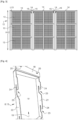
- FIG 2 illustrates a wall 10 similar to that of the figure 1 but in which the cladding elements are limited to elements 5, 6, 7, identical to those illustrated in figure 1 and located on the edges 11 of the wall 10 defining the height of the wall 10.
- the cladding elements are either absent or different from those of the figure 1 .
- the remainder of the wall 10 is occupied by photovoltaic panels 9 inserted in cassettes 8.
- the cassettes 8 and the panels 9 are all identical and arranged in parallel rows.
- the cassettes 8 and photovoltaic panels 9 illustrated in Figures 1 and 2 are identical. It is understood that, alternatively, they are different.
- FIG 3 illustrates another embodiment of the invention in which a wall 12 is entirely covered on its surface by cassettes 13 according to the invention, arranged in parallel rows.
- the orientation and/or the dimensions of the cassettes 13, also of rectangular shape like those 8 illustrated in Figures 1 and 2 are different, the cassettes 13 being oriented with their length L13 parallel to the height H12 of the wall 12.
- reinforcements 14 are placed regularly, parallel to the height H12 of the wall 12.
- the reinforcements 14 are part of the support allowing the cassettes 13 to be fixed to the wall 12.
- the reinforcements 14 are here configured as metal bars.
- Spaces 15, namely hollow joints, at functional and/or aesthetic purpose, are regularly arranged between the cassettes 13, on either side of some of the reinforcements 14. This gives a checkerboard appearance to the wall 12, while having optimal energy production in relation to the surface area available on the wall 12.
- a cassette 8 or 13 whose photovoltaic panel 9 is 110 cm by 175 cm provides an output power of 400 W, i.e. an efficiency of approximately 20%.
- a wall 1, 10 or 12 with a length of 10 m and a height of 4 m fully equipped with cassettes 8 or 13 can provide, over a period of 8 hours of sunshine, between 2000 W and 5000 W.
- the cladding elements 2 to 7 may be painted and/or of a different nature and/or with non-smooth and/or flat visible surfaces.
- FIG 4 illustrates an advantageous embodiment of a means of attaching the cassettes 8 or 13 to supports 16, visible in Figures 6 to 9 .
- the supports 16 are integral with the wall 1, 10, 12. They are made of a lightweight material, resistant to corrosion and inert with respect to the wall 1, 10, 12 and the cassette 8, 13.
- They are made of galvanized steel, stainless steel, aluminum, polymer, composite material.
- the supports 16 are here rails or profiled bars with a flat-bottomed omega cross-section.
- Flat tabs, particularly visible at the figure 7 are mounted perpendicular to the largest dimension of the support 16 and so as to be movable in translation along the support 16. These tabs 17 thus define adjustable attachment members for the cassettes 8 or 13 on the supports 16.
- each cassette 8, 13 is equipped with its own means of connection to the domestic or public network.
- the edge 18 of the cassette is configured in an L shape, one of the branches of the L extending towards the outside of the cassette 8, 13 from the open rear face 19 of the cassette 8, 13.
- the edge 18 is provided with orifices 20 allowing the passage of means for fixing, advantageously in a non-definitive manner, the cassette 8, 13 on the support 16.
- fixing means examples may be bolts, screws, studs or the like. It is thus possible to hang, in a non-definitive manner, the cassette 8 or 13 and to secure it by resting on the support 16 which is itself integral with the wall 1, 10, 12.
- each edge 21, 22 of the cassette 8 or 13 comprises two identical cutouts 23 distributed along the length of the edge.
- the number and/or shape of the cutouts are different, and the cutouts may also be non-identical on each edge or between the edges.
- Each cutout 23 is generally L-shaped with an open angle greater than 90° between the small and large branches of the L.
- the cutouts 23 are made so that the largest branch of the L is parallel to the length of the edge 21, 22, which makes it possible to define a tab 24.
- This tab 24 forms a hook allowing the cassette 8, 13 to be attached to an element of complementary shape, i.e. of dimensions and shapes adapted to be easily inserted into the notch of the hook 24 and retained by the latter.
- two identical hooks 24 are made on each edge 21, 22. It is thus possible either to fix the cassette 8, 13 at different heights on a support 16 or to fix it on two different parallel supports. Alternatively, the number and/or arrangement of the hooks 24 are different, knowing that in all cases with such a system a user takes the cassette 8, 13 and easily fixes it to a support 16 which has been previously secured to the wall 1, 10 or 12.
- FIG 5 thus illustrates the cassette 8, 13 in place and secured to a part of the support 16, namely with the edge 18 fixed, for example by screwing, bolting or otherwise, on the lateral parts 160 of the support 16, while at least one of the hooks 24 is engaged with at least one of the legs 17, the latter being positioned at the desired height on the support 16.
- the legs 17 are coated with a flexible material allowing blocking by jamming of the hook 24 of the cassette 8, 13 on the tab 17, thus avoiding any movement of the cassette 8, 13 in place on the support 16, this independently of the securing of the cassette 8, 13 by fixing the tab 18 on the support 16.
- FIG 7 illustrates the installation of a cassette 8, 13 on two parallel supports 16, the various elements being partially illustrated.
- the legs 17 of each support 16 have been previously positioned at the desired height, this by translation of the legs 17 along the support 16.
- the installation of the cassette 8, 13 is carried out by presenting the hooks 24 opposite the legs 17 then, without tools, by inserting the legs 24 in the cutouts 23, the hooks 24 passing behind the legs 17. It is thus easy for a single person to hang one or more cassettes 8, 13 in a short time, on the supports 16.
- the number of constituent elements of the support 16 is reduced in number to equip a wall since only regularly spaced vertical supports 16 are required, according to the width of the cassette 8, 13.
- the supports or rails 16 are originally equipped with a defined number of tabs 17, it being understood that the user can remove or add some if necessary.
- the installation of the support is quick and simple, while having a space-saving and lightweight support that does not modify the structural characteristics of the wall.
- the means for attaching the covering elements 2 to 7 are configured in a manner entirely similar to those of a cassette 8, 13, so that hooks 24 also equip the elements 2 to 7. The user can thus easily and quickly equip, at any time, a wall 1, 10, 12 indifferently with a cassette 8, 13 or a covering element 2 to 7 and change a cassette 8, 13 for an element 2 to 7 or vice versa.
- At least one cladding element 2 to 7 is a cassette 8 or 13 without a photovoltaic panel 9, the latter being replaced by a surface corresponding to the desired visual effect.
- the angles of inclination of the visible faces of the cladding elements 2 to 7 and/or the photovoltaic panels 9 are identical, with an inclination oriented in the same direction, arranged in rows and all being provided with the same means of attachment on the support 16, we obtain a wall 1, 10, 12 whose profile, in section, is visible at the figure 8 .
- the main plane P9 of the cassette 8, 13 therefore the active surface of the photovoltaic panel 9 or the plane P25 of the visible face 25 of the cladding element 2 to 7 is oriented angularly relative to the main plane P of the wall 1, 10, 12 with an angle of between 2° and 15°.
- each cassette 8, 13 or element 2 to 7 is in the vicinity of at least one other cassette 8, 13 or element 2 to 7 but in a non-integral manner. It is thus possible to change one or more cassettes 8, 13 and/or element 2 to 7.
- Such a configuration also makes it possible, if necessary, to insert an insulating, thermal and/or acoustic material, from the rear face 19 of the cassette 8, 13 or element 2 to 7 and/or at the level of the support 16 between the uprights of the latter.
- FIG 8 also illustrates the fact that the edges 21, 22 of the cassettes 8, 13 and the edges of the cladding elements 2 to 7 are not of constant width but in the shape of a triangle. It is this configuration that ensures the inclination of the photovoltaic panel 9 and the visible face 25 of the elements 2 to 7.
- the angle A is defined and constant for all the elements 2 to 7 and cassette 8, 13.
- the angle is different between the cassettes 8, 13 and the elements 2 to 7.
- the inclination angle is variable, the user being able to independently adjust the angle of each cassette 8, 13 and/or element 2 to 7.
- a known inclination means equips the rear of the photovoltaic panel 9 and/or the face 25. This may be, for example, jacks, a rack, a compass or other. Such a solution makes it possible to precisely adapt the inclination to the position of the wall and to the sunlight received.
- each cassette 8, 13 or a trim element 2 to 7 and/or the support 16 can equip at least one cassette 8, 13 or a trim element 2 to 7 and/or the support 16 with lighting elements or other elements such as water jets, display screens, loudspeakers, painted decorations or the like.
- lighting elements or other elements such as water jets, display screens, loudspeakers, painted decorations or the like.
- the open hollow configuration of each cassette 8, 13 makes it possible to provide air circulation at the back of the cassette which allows the photovoltaic panel to be ventilated and cooled 9.
- FIG 9 illustrates another embodiment of the invention in which a cassette 80 is generally of a pyramidal shape with a rectangular base with one face 90 incorporating the photovoltaic panel, the other face 91 being for aesthetic purposes.
- the face 91 is flat.
- it includes reliefs and/or colors and/or includes another element such as for example a display screen, lighting, a loudspeaker, water jets or others.
- only a portion of the cassette 80 is in this case dedicated to the production of energy by a photovoltaic panel 90.
- the cassette 80 can be equipped, temporarily or permanently, with another photovoltaic panel on its face 91, it being understood that the inclination being different, this second photovoltaic panel will have a different yield.
- the attachment of the cassettes 8, 13, 90 and/or the covering elements 2 to 7 is carried out by a magnetic connection with the support or by another means such as a tenon/mortise system, clips or other.
- the kit comprises several cladding elements and cassettes according to several dimensions, corresponding to three center distances between the rails constituting the support 16, for example center distances of 20 cm, 30 cm and 100 cm, which makes it possible to clad all lengths and heights of walls. It is understood that the number of cladding elements and/or cassettes making up a kit can be modified according to needs.
Landscapes
- Engineering & Computer Science (AREA)
- Architecture (AREA)
- Civil Engineering (AREA)
- Structural Engineering (AREA)
- Photovoltaic Devices (AREA)
- Finishing Walls (AREA)
Applications Claiming Priority (1)
| Application Number | Priority Date | Filing Date | Title |
|---|---|---|---|
| FR2211476A FR3141709A1 (fr) | 2022-11-04 | 2022-11-04 | Kit d’habillage de parois par des panneaux photovoltaiques |
Publications (3)
| Publication Number | Publication Date |
|---|---|
| EP4366158A1 EP4366158A1 (fr) | 2024-05-08 |
| EP4366158B1 true EP4366158B1 (fr) | 2025-01-01 |
| EP4366158C0 EP4366158C0 (fr) | 2025-01-01 |
Family
ID=84569733
Family Applications (1)
| Application Number | Title | Priority Date | Filing Date |
|---|---|---|---|
| EP23204971.8A Active EP4366158B1 (fr) | 2022-11-04 | 2023-10-20 | Kit d'habillage de parois par des panneaux photovoltaiques |
Country Status (4)
| Country | Link |
|---|---|
| EP (1) | EP4366158B1 (pl) |
| ES (1) | ES3006434T3 (pl) |
| FR (1) | FR3141709A1 (pl) |
| PL (1) | PL4366158T3 (pl) |
Family Cites Families (10)
| Publication number | Priority date | Publication date | Assignee | Title |
|---|---|---|---|---|
| DE6949099U (de) * | 1969-12-15 | 1970-03-26 | Erbsloeh Julius & August | Bauelementensatz zur herstellung dekorativer flaechen |
| DE102005038327A1 (de) * | 2005-05-18 | 2006-11-23 | Goldbeck Solar Gmbh | Verblendung für eine Fläche, insbesondere für eine Gebäudefläche |
| GB0803314D0 (en) * | 2008-02-23 | 2008-04-02 | Solar Century Holdings Ltd | Cladding a building with solar collecting devices |
| GB2462422B (en) * | 2008-08-05 | 2012-08-22 | Solar Century Holdings Ltd | Cladding a building with solar collection devices |
| SG168446A1 (en) | 2009-08-05 | 2011-02-28 | Housing And Dev Board | Supporting structure for green building facade |
| ITMI20120496A1 (it) * | 2012-03-28 | 2013-09-29 | Emanuele Lanteri | Sistema di pannelli di conversione di energia solare applicabile a superfici verticali |
| WO2013166523A1 (en) * | 2012-05-04 | 2013-11-07 | Bisem, Inc. | Net-zero energy curtain wall |
| JP6905936B2 (ja) * | 2015-11-13 | 2021-07-21 | 株式会社カネカ | 太陽電池モジュールの敷設構造、太陽電池モジュール、及び太陽電池モジュールの設置方法 |
| PL3182580T3 (pl) | 2015-12-15 | 2024-11-12 | Ml System Spółka Akcyjna | Zestaw elementów konstrukcyjnych umożliwiających rozłączne połączenie modułu fotowoltaicznego fasady wentylowanej z ocieploną ścianą frontową budynku |
| FR3116552B1 (fr) | 2020-11-23 | 2023-03-31 | Commissariat Energie Atomique | Structure photovoltaïque destinée à couvrir au moins une partie d’au moins une façade d’un batiment |
-
2022
- 2022-11-04 FR FR2211476A patent/FR3141709A1/fr active Pending
-
2023
- 2023-10-20 EP EP23204971.8A patent/EP4366158B1/fr active Active
- 2023-10-20 ES ES23204971T patent/ES3006434T3/es active Active
- 2023-10-20 PL PL23204971.8T patent/PL4366158T3/pl unknown
Also Published As
| Publication number | Publication date |
|---|---|
| ES3006434T3 (en) | 2025-03-18 |
| FR3141709A1 (fr) | 2024-05-10 |
| EP4366158C0 (fr) | 2025-01-01 |
| EP4366158A1 (fr) | 2024-05-08 |
| PL4366158T3 (pl) | 2025-04-28 |
Similar Documents
| Publication | Publication Date | Title |
|---|---|---|
| CA2674794C (en) | Mounting device for solar modules having a large aspect ratio | |
| EP1379740A1 (fr) | Toile photogeneratrice et support pour une telle toile | |
| WO2011023903A2 (fr) | Systeme de montage de modules photovoltaiques | |
| WO2009023454A2 (en) | Framed solar module and method of installing | |
| WO2011023898A1 (fr) | Dispositif de fixation d'au moins un panneau sur une structure porteuse | |
| FR3018302A1 (fr) | Ombriere pour zone de stationnement de vehicule comportant un cadre de toiture forme de pannes et/ou de traverses | |
| FR3074206B1 (fr) | Dispositif de fixation de lamelles a panneau grillage rigide, kit de fixation de lamelles a panneau grillage rigide et cloture occultante equipee d’un tel kit | |
| EP4366158B1 (fr) | Kit d'habillage de parois par des panneaux photovoltaiques | |
| FR2752002A1 (fr) | Plate-forme mobile pour piscine ou analogue | |
| FR2934623A1 (fr) | Assemblage d'un dispositif de garde-corps et d'un panneau solaire photovoltaique | |
| EP4002684B1 (fr) | Structure photovoltaïque destinée à couvrir au moins une partie d'au moins une façade d'un batiment | |
| FR3136802A1 (fr) | Kit de clôture photovoltaïque bifacial | |
| FR2941985A1 (fr) | Panneau monobloc prefabrique pour la construction de mur | |
| FR3063339A1 (fr) | Ensemble de production d'energie solaire avec montage integre et gestion de l'eau et procede pour fournir celui-ci | |
| FR2945561A1 (fr) | Systeme de fixation de modules photovoltaiques sur une surface de couverture et surface de couverture correspondante | |
| FR2971839A1 (fr) | Structure de montage, kit pour la realisation d'une telle structure, systeme de recuperation d'energie solaire comprenant une telle structure et installation comprenant un tel systeme | |
| FR2950421A1 (fr) | Systeme de montage et de fixation pour panneaux solaires | |
| KR102081895B1 (ko) | 태양광발전 모듈의 다각 거치 장치 | |
| EP2489957A2 (fr) | Structure de montage, kit pour la réalisation d'une telle structure, système de récupération d'energie solaire comprenant une telle structure, installation comprenant un tel système et procède de montage d'un tel système | |
| WO2011098678A1 (fr) | Panneau monobloc préfabriqué pour la construction de mur | |
| KR101266186B1 (ko) | 차광막 구조물 | |
| JP2014084587A (ja) | 太陽光発電パネルの取り付け構造 | |
| WO2024083468A1 (fr) | Toitures et facades vegetalisees photovoltaïques | |
| FR2691195A1 (fr) | Perfectionnement au faîtage de constructions du genre vérandas, piscines, spas ou autres. | |
| FR2963412A1 (fr) | Dispositif d'installation pour panneaux solaires sur une structure de batiment |
Legal Events
| Date | Code | Title | Description |
|---|---|---|---|
| PUAI | Public reference made under article 153(3) epc to a published international application that has entered the european phase |
Free format text: ORIGINAL CODE: 0009012 |
|
| STAA | Information on the status of an ep patent application or granted ep patent |
Free format text: STATUS: REQUEST FOR EXAMINATION WAS MADE |
|
| 17P | Request for examination filed |
Effective date: 20231020 |
|
| AK | Designated contracting states |
Kind code of ref document: A1 Designated state(s): AL AT BE BG CH CY CZ DE DK EE ES FI FR GB GR HR HU IE IS IT LI LT LU LV MC ME MK MT NL NO PL PT RO RS SE SI SK SM TR |
|
| GRAP | Despatch of communication of intention to grant a patent |
Free format text: ORIGINAL CODE: EPIDOSNIGR1 |
|
| STAA | Information on the status of an ep patent application or granted ep patent |
Free format text: STATUS: GRANT OF PATENT IS INTENDED |
|
| RAP1 | Party data changed (applicant data changed or rights of an application transferred) |
Owner name: ULTRAWATT |
|
| RIC1 | Information provided on ipc code assigned before grant |
Ipc: E04F 13/08 20060101ALI20241017BHEP Ipc: H02S 20/26 20140101AFI20241017BHEP |
|
| GRAS | Grant fee paid |
Free format text: ORIGINAL CODE: EPIDOSNIGR3 |
|
| GRAA | (expected) grant |
Free format text: ORIGINAL CODE: 0009210 |
|
| STAA | Information on the status of an ep patent application or granted ep patent |
Free format text: STATUS: THE PATENT HAS BEEN GRANTED |
|
| INTG | Intention to grant announced |
Effective date: 20241030 |
|
| AK | Designated contracting states |
Kind code of ref document: B1 Designated state(s): AL AT BE BG CH CY CZ DE DK EE ES FI FR GB GR HR HU IE IS IT LI LT LU LV MC ME MK MT NL NO PL PT RO RS SE SI SK SM TR |
|
| REG | Reference to a national code |
Ref country code: GB Ref legal event code: FG4D Free format text: NOT ENGLISH |
|
| REG | Reference to a national code |
Ref country code: CH Ref legal event code: EP |
|
| REG | Reference to a national code |
Ref country code: DE Ref legal event code: R096 Ref document number: 602023001590 Country of ref document: DE |
|
| REG | Reference to a national code |
Ref country code: IE Ref legal event code: FG4D Free format text: LANGUAGE OF EP DOCUMENT: FRENCH |
|
| U01 | Request for unitary effect filed |
Effective date: 20250128 |
|
| U07 | Unitary effect registered |
Designated state(s): AT BE BG DE DK EE FI FR IT LT LU LV MT NL PT RO SE SI Effective date: 20250203 |
|
| REG | Reference to a national code |
Ref country code: ES Ref legal event code: FG2A Ref document number: 3006434 Country of ref document: ES Kind code of ref document: T3 Effective date: 20250318 |
|
| REG | Reference to a national code |
Ref country code: GR Ref legal event code: EP Ref document number: 20250400447 Country of ref document: GR Effective date: 20250409 |
|
| PG25 | Lapsed in a contracting state [announced via postgrant information from national office to epo] |
Ref country code: IS Free format text: LAPSE BECAUSE OF FAILURE TO SUBMIT A TRANSLATION OF THE DESCRIPTION OR TO PAY THE FEE WITHIN THE PRESCRIBED TIME-LIMIT Effective date: 20250501 |
|
| PG25 | Lapsed in a contracting state [announced via postgrant information from national office to epo] |
Ref country code: HR Free format text: LAPSE BECAUSE OF FAILURE TO SUBMIT A TRANSLATION OF THE DESCRIPTION OR TO PAY THE FEE WITHIN THE PRESCRIBED TIME-LIMIT Effective date: 20250101 |
|
| PG25 | Lapsed in a contracting state [announced via postgrant information from national office to epo] |
Ref country code: CZ Free format text: LAPSE BECAUSE OF FAILURE TO SUBMIT A TRANSLATION OF THE DESCRIPTION OR TO PAY THE FEE WITHIN THE PRESCRIBED TIME-LIMIT Effective date: 20250101 |
|
| PG25 | Lapsed in a contracting state [announced via postgrant information from national office to epo] |
Ref country code: SM Free format text: LAPSE BECAUSE OF FAILURE TO SUBMIT A TRANSLATION OF THE DESCRIPTION OR TO PAY THE FEE WITHIN THE PRESCRIBED TIME-LIMIT Effective date: 20250101 |
|
| PG25 | Lapsed in a contracting state [announced via postgrant information from national office to epo] |
Ref country code: SK Free format text: LAPSE BECAUSE OF FAILURE TO SUBMIT A TRANSLATION OF THE DESCRIPTION OR TO PAY THE FEE WITHIN THE PRESCRIBED TIME-LIMIT Effective date: 20250101 |
|
| PLBE | No opposition filed within time limit |
Free format text: ORIGINAL CODE: 0009261 |
|
| STAA | Information on the status of an ep patent application or granted ep patent |
Free format text: STATUS: NO OPPOSITION FILED WITHIN TIME LIMIT |
|
| U20 | Renewal fee for the european patent with unitary effect paid |
Year of fee payment: 3 Effective date: 20251028 |