EP4366136A1 - Rotor und motor - Google Patents
Rotor und motor Download PDFInfo
- Publication number
- EP4366136A1 EP4366136A1 EP22832547.8A EP22832547A EP4366136A1 EP 4366136 A1 EP4366136 A1 EP 4366136A1 EP 22832547 A EP22832547 A EP 22832547A EP 4366136 A1 EP4366136 A1 EP 4366136A1
- Authority
- EP
- European Patent Office
- Prior art keywords
- rotor core
- rotor
- cover
- plate
- magnetic pole
- Prior art date
- Legal status (The legal status is an assumption and is not a legal conclusion. Google has not performed a legal analysis and makes no representation as to the accuracy of the status listed.)
- Pending
Links
Images


Classifications
-
- H—ELECTRICITY
- H02—GENERATION; CONVERSION OR DISTRIBUTION OF ELECTRIC POWER
- H02K—DYNAMO-ELECTRIC MACHINES
- H02K1/00—Details of the magnetic circuit
- H02K1/06—Details of the magnetic circuit characterised by the shape, form or construction
- H02K1/22—Rotating parts of the magnetic circuit
- H02K1/27—Rotor cores with permanent magnets
- H02K1/2706—Inner rotors
- H02K1/272—Inner rotors the magnetisation axis of the magnets being perpendicular to the rotor axis
- H02K1/274—Inner rotors the magnetisation axis of the magnets being perpendicular to the rotor axis the rotor consisting of two or more circumferentially positioned magnets
- H02K1/2753—Inner rotors the magnetisation axis of the magnets being perpendicular to the rotor axis the rotor consisting of two or more circumferentially positioned magnets the rotor consisting of magnets or groups of magnets arranged with alternating polarity
- H02K1/276—Magnets embedded in the magnetic core, e.g. interior permanent magnets [IPM]
- H02K1/2766—Magnets embedded in the magnetic core, e.g. interior permanent magnets [IPM] having a flux concentration effect
- H02K1/2773—Magnets embedded in the magnetic core, e.g. interior permanent magnets [IPM] having a flux concentration effect consisting of tangentially magnetized radial magnets
-
- H—ELECTRICITY
- H02—GENERATION; CONVERSION OR DISTRIBUTION OF ELECTRIC POWER
- H02K—DYNAMO-ELECTRIC MACHINES
- H02K1/00—Details of the magnetic circuit
- H02K1/06—Details of the magnetic circuit characterised by the shape, form or construction
- H02K1/22—Rotating parts of the magnetic circuit
- H02K1/27—Rotor cores with permanent magnets
- H02K1/2706—Inner rotors
- H02K1/272—Inner rotors the magnetisation axis of the magnets being perpendicular to the rotor axis
- H02K1/274—Inner rotors the magnetisation axis of the magnets being perpendicular to the rotor axis the rotor consisting of two or more circumferentially positioned magnets
Definitions
- the present invention relates to a rotor and a motor.
- IPM rotors In inner rotor type motors, so-called IPM rotors are known.
- IPM rotors plate-shaped magnets magnetized in front and back directions are disposed in a spoke-like shape in a radial direction so that two adjacent plate-shaped magnets repel each other.
- a locking structure is sometimes used for preventing the plate-shaped magnet from jumping outward in the radial direction due to a repulsive force with an adjacent plate-shaped magnet or a centrifugal force when the rotor rotates.
- an object is to provide a rotor and a motor capable of improving motor characteristics.
- a rotor in one aspect, includes a rotor core, a magnet, and a cover.
- the rotor core includes an annular portion and a plurality of magnetic pole pieces.
- the magnet is disposed between two magnetic pole pieces adjacent to each other in a circumferential direction of the plurality of magnetic pole pieces.
- the cover covers an outer peripheral portion of the magnet, and is formed of a non-magnetic material or a member having magnetism lower than magnetism of the rotor core.
- the motor characteristics can be improved.
- FIG. 1 An embodiment of a rotor disclosed in the present application will be elaborated below with reference to the drawings. Note that the dimensional relationships between elements and the ratios of the elements in the drawings may differ from an actual configuration.
- the drawings may include parts having mutually different dimensional relationships and proportions.
- a coordinate system including at least any one of an axial direction (rotation axis direction of a motor 1), a radial direction, or a circumferential direction of the motor 1 may be illustrated for the purpose of facilitating explanation.
- the motor 1 will be described later.
- the rotation axis direction of the motor 1 may be simply referred to as an "axial direction" below.
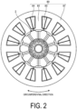
- FIG. 1 is a perspective view illustrating one example of a motor according to a first embodiment. However, a stator is omitted in FIG. 1 .
- FIG. 2 is a cross-sectional view illustrating one example of the motor according to the first embodiment. FIG. 2 illustrates a cross section taken along the line A-A in FIG. 1 .
- the motor 1 according to the present embodiment includes a rotor 2 and a stator 80. Note that the motor 1 described in each embodiment is an inner rotor type brushless motor. Further, the motor 1 in each embodiment is housed in, for example, a frame (not illustrated).
- the stator 80 includes a yoke 81, teeth 82, coils 83, and insulators 84.
- the yoke 81 is an annular member formed at the outer peripheral side of the stator 80.
- the teeth 82 protrude inward in the radial direction from the yoke 81.
- the yoke 81 and the teeth 82 are formed by, for example, punching a flat plate-shaped member formed of a magnetic material such as a magnetic steel plate into a shape illustrated in FIG. 2 and stacking a plurality of the punched members in the axial direction.
- the coils 83 are wound around the teeth 82 via the insulators 84, for example.
- the rotor 2 is rotatably inserted into the stator 80 in the radial direction.
- the rotor 2 includes a rotor core 10, covers 20 and 30, a plurality of plate-shaped magnets 40, and a shaft 90.
- the shaft 90 is inserted into the rotor 2 in the radial direction.
- the rotor core 10 has a stacked structure obtained by stacking a plurality of steel plate cores formed of a soft magnetic material such as a silicon steel plate.
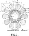
- FIG. 3 is a cross-sectional view illustrating an example of a rotor core according to the first embodiment.
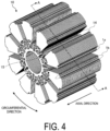
- FIG. 4 is a perspective view illustrating an example of the rotor core according to the first embodiment.
- FIG. 3 illustrates a cross section taken along the line A-A in FIG. 4 .
- the rotor core 10 includes a plurality of magnetic pole pieces 11, coupling portions 12, support portions 15, and an annular portion 19.
- the rotor core 10 may further include lightening portions 16, 17, and 18 in order to reduce leakage magnetic flux.
- the magnetic pole pieces 11 when the magnetic pole pieces 11 are distinguished from each other, they may be referred to as magnetic pole pieces 11A to 11J below.
- the plurality of magnetic pole pieces 11 extend outward in the radial direction from the annular portion 19.
- the plurality of magnetic pole pieces 11 are arranged side by side in the circumferential direction.
- Each of the magnetic pole pieces 11 includes end portions 11p and 11q extending substantially in the radial direction and an outer peripheral portion 11r extending in the circumferential direction.
- the end portion 11p opposes, across a gap 14 in the circumferential direction, the end portion 11q of the circumferentially adjacent magnetic pole piece 11.
- the outer peripheral portion 11r constitutes the outer periphery of the rotor 2.
- FIG. 5 is an enlarged cross-sectional view illustrating an example of a recessed portion of the rotor core according to the first embodiment.
- FIG. 5 is an enlarged view of a portion illustrated in a frame F1 in FIG. 3 . As illustrated in FIG.
- the recessed portion 1a includes a first portion 1c connected to the outer peripheral portion 11r, and a second portion 1e constituting an inner diameter-side end portion of the recessed portion 1a and connected to the end portion 11p.
- the recessed portion 1b includes a first portion 1d connected to the outer peripheral portion 11r, and a second portion 1f constituting an inner diameter-side end portion of the recessed portion 1b and connected to the end portion 11q. Note that the outer peripheral portion 11r, the first portion 1c of the recessed portion 1a, and the second portion 1e of the recessed portion 1a are continuously formed.
- the outer peripheral portion 11r, the first portion 1d of the recessed portion 1b, and the second portion 1f of the recessed portion 1b are continuously formed.
- the outer peripheral portion 11r, the second portion 1e of the recessed portion 1a, and the second portion 1f of the recessed portion 1b constitute an outer peripheral end portion of the rotor core 10.
- the recessed portion 1b formed at the magnetic pole piece 11A opposes, in the circumferential direction, the recessed portion 1a formed at the magnetic pole piece 11J circumferentially adjacent to the magnetic pole piece 11A. More specifically, the first portion 1d of the recessed portion 1b of the magnetic pole piece 11A and the first portion 1c of the recessed portion 1a of the magnetic pole piece 11J oppose each other in the circumferential direction. Further, as illustrated in FIG. 5 , the recessed portion 1b is formed such that an angle R formed by the second portion 1f and the end portion 11q is an acute angle. The same applies to the recessed portion 1a.
- the shaft 90 is inserted into the annular portion 19 in the radial direction via the inner peripheral portions 29 and 39 of the covers 20 and 30.
- the plurality of magnetic pole pieces 11 and the annular portion 19 are coupled to each other in the radial direction by the coupling portions 12.
- the inner diameter of the annular portion 19 is formed to be larger than the outer diameters of the inner peripheral portions 29 and 39 of the covers 20 and 30.
- the support portion 15 extends outward in the radial direction from the annular portion 19. In other words, the support portion 15 protrudes outward in the radial direction from the annular portion 19. As illustrated in FIG. 3 , the support portion 15 opposes the gap 14 in the radial direction.
- the width of the gap 14 is formed to be substantially the same as or slightly larger than the width (the length in the circumferential direction) of the plate-shaped magnet 40.
- air layers 14a and 14b are formed at both sides in the circumferential direction at the inner side in the radial direction of the gap 14, respectively. Note that at this time, the air layer 14a and the air layer 14b are disposed adjacent to each other in the circumferential direction of the support portion 15.
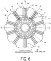
- FIG. 6 is a cross-sectional view illustrating an example of the rotor according to the first embodiment.
- FIG. 6 illustrates a cross section of the rotor 2 taken along the line A-A in FIG. 4 .
- the rotor 2 in the present embodiment includes ten plate-shaped magnets 40. Note that when the plate-shaped magnets 40 are distinguished from each other, they may be referred to as plate-shaped magnets 4a to 4j below.
- the plate-shaped magnet 40 includes a radially outer end surface 41, a radially inner end surface 42, a circumferentially counterclockwise-side end surface 43, and a circumferentially clockwise-side end surface 44.
- the plate-shaped magnet 40 includes an N-pole 4N and an S-pole 4S.
- two plate-shaped magnets 40 adjacent to each other in the circumferential direction are disposed such that the same poles oppose each other.
- two plate-shaped magnets 4a and 4b adjacent to each other in the circumferential direction are disposed such that the N-poles 4N oppose each other.
- the two plate-shaped magnets 4j and 4a adjacent to each other in the circumferential direction are disposed such that the S-poles 4S oppose each other.
- the radially inner end surface 42 of the plate-shaped magnet 40 is supported in the radial direction by the support portion 15 of the rotor core 10. Specifically, the end surface 42 is supported by the support portion 15 in the vicinity of the center of the plate-shaped magnet 40 in the circumferential direction.
- the support portion 15 supports a switching point, and the N-pole 4N and the S-pole 4S of the plate-shaped magnets 40 are switched at the switching point.
- the air layer 14a and 14b are provided at both end portions of the end surface 42 in the circumferential direction without a conventional locking structure, the magnetic flux generated from both end portions of the end surface 42 in the circumferential direction are guided to the rotor core 10.
- the magnetic flux not interlinking with the stator winding and directly flowing into the opposite magnetic pole at the other surface of the plate-shaped magnet decreases. According to such a configuration, it is possible to suppress leakage of the magnetic flux from both end portions in the circumferential direction at the radially inner side of the plate-shaped magnet 40.
- FIG. 7 is a perspective view illustrating an example of a cover according to the first embodiment.
- FIG. 7 is a perspective view illustrating an example of a cover according to the first embodiment.
- FIG. 8 is a cross-sectional perspective view illustrating an example of the cover according to the first embodiment.
- FIG. 8 illustrates a cross section taken along the line C-C in FIG. 7 .
- the cover 20 is attached to the rotor core 10 from the positive direction side in the axial direction
- the cover 30 is attached to the rotor core 10 from the negative direction side in the axial direction.
- the cover 20 includes a plurality of protruding portions 21, a planar portion 25, and an inner peripheral portion 29. Further, the cover 20 may further include a plurality of opening portions 22. Note that although the cover 20 is illustrated in FIG. 7 and the cover 30 is illustrated in FIG. 8 , the covers 20 and 30 in the present embodiment have the same shape, and matters described below with respect to the cover 20 also apply to the cover 30 unless otherwise specified.
- the cover 30 also includes a plurality of protruding portions 31, a planar portion 35, an inner peripheral portion 39, and a plurality of opening portions 32. Similarly, matters described with respect to the cover 30 also apply to the cover 20 unless otherwise specified.
- the cover 20 is formed of a non-magnetic material such as brass. Further, the cover 20 may be formed by bending a material having magnetism lower than magnetism of the magnetic steel plate constituting the rotor core 10, such as austenitic stainless steel.
- each of the protruding portions 21 protrudes from the planar portion 25 in the axial direction.
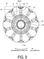
- the plurality of protruding portions 21 are arranged at equal intervals in the circumferential direction. More specifically, as illustrated in FIGS. 9 and 10 , the same number of protruding portions 21 as the number of plate-shaped magnets 40 are formed at positions in contact with parts of the plate-shaped magnets 40, for example, parts of the end surfaces 41 at the axially positive direction side.
- FIG. 9 is a cross-sectional view illustrating an example of the rotor core according to the first embodiment. In FIG. 9 , the plate-shaped magnets are omitted. FIG.
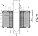
- FIG. 10 is a side cross-sectional view illustrating an example of the rotor core according to the first embodiment.
- FIG. 10 illustrates a cross section taken along the line B-B in FIGS. 1 and 9.
- FIG. 9 illustrates a cross section taken along the line D-D in FIG. 1 or FIG. 10 .
- the plate-shaped magnet 40 in addition to the end surfaces 41 to 44 illustrated in FIGS. 6 and 9 , the plate-shaped magnet 40 further includes an end surface 45 at the axially positive direction side and an end surface 46 at the axially negative direction side.
- each protruding portion 21 of the cover 20 protrudes toward the axially negative direction side
- each protruding portion 31 of the cover 30 protrudes toward the axially positive direction side.
- a part at the axially positive direction side is in contact with the protruding portion 21 of the cover 20
- a part at the axially negative direction side is in contact with the protruding portion 31 of the cover 30.
- the opening portions 22 are formed extending through the planar portion 25 in the axial direction. As illustrated in FIG. 10 , the opening portions 22 oppose the end surfaces 45 of the plate-shaped magnets 40 at the axially positive direction side. In this case, as illustrated in FIG. 1 , the plate-shaped magnets 40 are visually recognized from the axially positive direction side through the opening portions 22.
- the inner peripheral portion 29 protrudes from the planar portion 25 in the axial direction similarly to the protruding portion 21.
- the outer diameter of the inner peripheral portion 29 is, for example, substantially the same as or slightly larger than the inner diameter of the annular portion 19 of the rotor core 10.
- the inner diameter of the inner peripheral portion 29 is, for example, substantially the same as or slightly smaller than the outer diameter of the shaft 90.
- the covers 20 and 30 are inserted by being press-fitted between the annular portion 19 of the rotor core 10 and the shaft 90 in the radial direction.
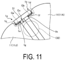
- FIG. 11 is an enlarged cross-sectional view illustrating an example of the rotor according to the first embodiment.
- FIG. 11 is an enlarged view of a portion indicated by a frame F2 in FIG. 9 .
- the radially outer end surface 41 of the plate-shaped magnet 40 is in contact with the protruding portion 31 of the cover 30, and protrudes outward in the radial direction beyond the recessed portions 1a and 1b, more specifically, beyond the second portion 1e of the recessed portion 1a and the second portion 1f of the recessed portion 1b.
- a gap Ga in the radial direction is formed between the protruding portion 31 and the second portion 1e of the recessed portion 1a of the rotor core 10.
- a gap Gb in the radial direction is formed between the protruding portion 31 and the second portion 1f of the recessed portion 1b. Further, a gap Gx in the radial direction is formed between corner portions 1g and 1h and the cover 20. In the present embodiment, the corner portions 1g and 1h have an acute angle (angle R illustrated in FIG. 5 ).
- the covers 20, 30 can be easily disposed, and the length of the magnetic path of the leakage magnetic flux is increased and the magnetic resistance is increased, so that the leakage magnetic flux can be suppressed.
- the corner portions 1g and 1h to have an acute angle, the magnetic path of the leakage magnetic flux connected from the recessed portions 1a and 1b to the other recessed portion also goes out to the air layer substantially perpendicularly from the recessed portions 1a and 1b.
- the distance to the other recessed portion can be further increased, and the magnetic resistance is increased, so that the leakage of the magnetic flux is further suppressed.
- each of the magnetic pole pieces 11 it is not necessary to install a locking structure by the rotor core, and the plate-shaped magnet 40 protrudes outward in the radial direction from the recessed portions 1a and 1b of the rotor core 10 but is positioned inward in the radial direction of the outer peripheral portion 11r. According to such a configuration, cogging and torque ripple can be easily adjusted by changing the width or curvature of the outer peripheral portion 11r.
- the rotor 2 in the present embodiment includes the rotor core 10, the magnets 40, and the covers 20, 30.
- the rotor core 10 includes the annular portion 19 and the plurality of magnetic pole pieces 11.
- the magnet 40 is disposed between two magnetic pole pieces adjacent to each other in a circumferential direction of the plurality of magnetic pole pieces 11.
- the cover 20, 30 covers the outer peripheral portion of the magnets 40, and is formed of a non-magnetic member or a member having magnetism lower than magnetism of the rotor core 10. According to such a configuration, the leakage of the magnetic flux via the rotor core 10 can be suppressed, so that the motor characteristics can be improved.
- the two adjacent magnetic pole pieces 11 include the recessed portions 1a and 1b recessed in the radial direction, and the recessed portions 1a and 1b included in the two adjacent magnetic pole pieces 11 are each disposed opposing the magnet 40 in the circumferential direction. Further, in the radial direction, the gaps Ga and Gb are formed between inner diameter-side end portions 1e and 1f of the recessed portions 1a and 1b and the covers 20 and 30. According to such a configuration, it is possible to suppress the magnetic flux leaking outward in the radial direction.
- the covers 20 and 30 are formed of a non-magnetic member or a member having magnetism lower than magnetism of a member forming the magnetic pole piece 11 of the rotor core 10.
- the plate-shaped magnet 40 of the present embodiment at least parts of the radially outer end surface 41 are in contact with the non-magnetic or low-magnetic covers 20 and 30. Since a locking structure by the rotor core 10 is not disposed in the radial direction at the radially outer end surface 41 of the plate-shaped magnet 40, the magnetic flux not interlinking with the stator winding and directly flowing into the opposite magnetic pole at the other surface of the plate-shaped magnet is suppressed. According to such a configuration, the leakage magnetic flux is reduced.
- the cover 20 in the present embodiment may include the opening portions 22 opening in the axial direction.
- the opening portions 22 oppose the magnets 40 in the axial direction.
- the plate-shaped magnets 40 and the rotor core 10 can be easily fixed to each other by injecting an adhesive or the like from the opening portions 22.
- FIG. 12 is a perspective view illustrating an example of a rotor according to a second embodiment.
- a motor A1 according to the second embodiment includes a rotor A2 and a stator 80.
- the stator is omitted in FIG. 12 . Note that in the following embodiment and modifications, the same portions as those illustrated in the drawings described above are denoted by the same reference signs, and the redundant description will be omitted.
- the rotor A2 illustrated in FIG. 12 includes a rotor core 50, covers 60 and 70, plate-shaped magnets 40, and a shaft 90.
- the rotor core 50 includes a plurality of magnetic pole pieces 51, coupling portions 52, and an annular portion 59.
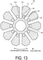
- FIG. 13 is a cross-sectional view illustrating an example of a rotor core according to the second embodiment.
- the magnetic pole piece 51 in the second embodiment includes the outer peripheral portion 11r extending in the circumferential direction, and end portions 51p and 51q extending in the radial direction.
- the plurality of magnetic pole pieces 51 and the annular portion 59 are coupled to each other in the radial direction by the coupling portions 52.
- the magnetic pole piece 51 may further include a lightening portion 58.
- FIG. 14 is a cross-sectional view illustrating an example of the rotor according to the second embodiment.
- the end portions 51p and 51q in the second embodiment extend inward in the radial direction beyond the radially inner end surface 42 of the plate-shaped magnet 40.
- the radially inner end surface 42 of the plate-shaped magnet 40 in the second embodiment is supported not by the support portion 15 but by the cover 70.
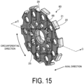
- FIG. 15 is a perspective view illustrating one example of a cover according to the second embodiment.
- FIG. 16 is a cross-sectional perspective view illustrating an example of the cover according to the second embodiment.
- FIG. 16 illustrates a cross section taken along the line C-C in FIG. 15 .
- the covers 60 and 70 have the same shape, and matters described below with respect to the cover 60 also apply to the cover 70 unless otherwise specified. Similarly, matters described with respect to the cover 70 also apply to the cover 60 unless otherwise specified.
- the cover 60 is formed of a non-magnetic material such as brass or a material having magnetism lower than magnetism of the magnetic steel plate constituting the rotor core 50. As illustrated in FIG. 15 , the cover 60 further includes contact portions 66 in addition to the protruding portions 21, the opening portions 22, the planar portion 25, and the inner peripheral portion 29.
- the contact portions 66 of the cover 60 protrude from the planar portion 25 in the axial direction, similarly to the protruding portions 21 and the inner peripheral portion 29.
- the contact portions 66 are arranged at equal intervals in the circumferential direction to oppose the plate-shaped magnets 40 in the radial direction, and the number of the contact portions 66 is the same as the number of the plate-shaped magnets 40.
- portions extending through the planar portion 25 in the axial direction are formed around the contact portions 66.
- the contact portions 66 of the cover 60 protrude toward the axially negative direction side
- the contact portions 76 of the cover 70 protrude toward the axially positive direction side.
- FIG. 17 is a side cross-sectional view illustrating an example of the rotor according to the second embodiment.
- the contact portion 66 is inserted into the gap 54 of the rotor core 50 from the axially positive direction side.
- the contact portion 66 supports the radially inner end surface 42 of the plate-shaped magnet 40 from the radially inner side.
- the plate-shaped magnet 40 is supported in the radial direction by the protruding portion 21 and the contact portion 66 of the cover 60, and by the protruding portion 31 and the contact portion 76 of the cover 70.
- the cover 60 includes the contact portions 66, and the contact portions 66 are in contact with the magnets 40 at the radially inner end surfaces 42 of the magnets 40. According to such a configuration, leakage of the magnetic flux not interlinking with the stator winding and directly flowing into the opposite magnetic pole at the other surface of the plate-shaped magnet from one of the radially inner end surfaces of the plate-shaped magnet 40 is suppressed.
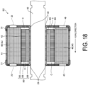
- FIG. 18 is a side cross-sectional view illustrating an example of a rotor according to a first modification.
- the axial length of the rotor core B0 is smaller than the length of the plate-shaped magnet 40.
- a space C is formed between the rotor core B0 and the covers 20 and 30 in the axial direction.
- the end surfaces 45 and 46 of the plate-shaped magnet 40 in the axial direction do not oppose a support portion B5 of the rotor core B0 in the radial direction.
- the inner peripheral portion 29 of the cover 20 and the inner peripheral portion 39 of the cover 30 are disposed between the end surfaces 45 and 46, and the shaft 90 opposing the plate-shaped magnets 40 in the radial direction.
- the magnetic flux of the plate-shaped magnet 40 can be converged into a range opposing the stator, and the magnetic flux interlinking with the stator winding can be increased, whereby the characteristics of the motor can be improved.
- the end portion in the axial direction of the radially outer end surface 41 of the plate-shaped magnet 40 is, in the entire circumferential direction, in contact with the protruding portion 21, and the recessed portions 1a and 1b are in contact with the vertex of the protruding portion 21.
- the embodiment is not limited to this.
- a rotor core C0 may be configured such that only a part of the plate-shaped magnet 40 in the circumferential direction, more specifically, only the vicinity of the central portion in the circumferential direction is in contact with a protruding portion C31.
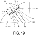
- FIG. 19 is an enlarged cross-sectional view illustrating an example of a rotor according to a second modification.
- the protruding portion C31 of a cover C30 is in contact with neither of the recessed portions 1a and 1b.
- the protruding portion C31 may cover only the central portion of the plate-shaped magnet 40 as illustrated in FIG. 19 .
- the outer peripheral portion 11r, the first portion 1c, the second portion 1e, and the end portion 11p illustrated in FIG. 5 are continuously connected by, for example, a curved line but, as this is not a limitation, may be discontinuously formed in straight lines.
- the outer peripheral portion 11r, the first portion 1d, the second portion 1f, and the end portion 11q may be formed in a curved shape.
- the first portions 1c and 1d may be in contact with the entire end surfaces of the protruding portion 21 of the cover 20 in the circumferential direction.
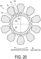
- air layers extending in the circumferential direction and corresponding to the reference signs 14a and 14b of FIG. 3 are not formed at the radially inner side of the gap 54, but this is not a limitation, and as illustrated in FIG. 20 , an annular portion D9 and support portions D5 protruding outward in the radial direction from the annular portion D9 may be provided, and air layers D4a and D4b extending in the circumferential direction of a gap D4 may be provided. In other words, the support portion D5 and the air layers D4a and D4b are disposed adjacent to each other in the circumferential direction.
- FIG. 20 is a cross-sectional view illustrating an example of a rotor core according to a third modification.
- a rotor core D0 of the third modification as well, a plurality of magnetic pole pieces D1 and an annular portion D9 are coupled in the radial direction by coupling portions D2. According to such a configuration, it is possible to suppress leakage of the magnetic flux from both end portions in the circumferential direction at the radially inner side of the plate-shaped magnet 40.
- FIG. 21 is a cross-sectional view illustrating an example of a rotor according to a fourth modification.
- the outer peripheral portion E1r and the end portions E1p and E1q are continuously disposed. According to such a configuration, even a multi-pole or small-diameter rotor core E0 can be easily manufactured.
- the protruding portion C31 of the cover C30 in the fourth modification is in contact with only the vicinity of the central portion of the plate-shaped magnet 40 in the circumferential direction as in the second modification.
- the radially inner end surface 42 of the plate-shaped magnet 40 is supported by a contact portion C36 of the cover C30 but, as this is not a limitation, may be supported by the support portion D5 of the rotor core D0 as illustrated in FIG. 20 .
- a configuration corresponding to the coupling portions 52 in FIG. 13 is not provided, but the lightening portions 58 and the coupling portions 52 may be provided similarly to FIG. 13 .
Landscapes
- Engineering & Computer Science (AREA)
- Power Engineering (AREA)
- Permanent Field Magnets Of Synchronous Machinery (AREA)
- Iron Core Of Rotating Electric Machines (AREA)
Applications Claiming Priority (2)
| Application Number | Priority Date | Filing Date | Title |
|---|---|---|---|
| JP2021107259A JP7825386B2 (ja) | 2021-06-29 | 2021-06-29 | ロータ及びモータ |
| PCT/JP2022/016030 WO2023276386A1 (ja) | 2021-06-29 | 2022-03-30 | ロータ及びモータ |
Publications (2)
| Publication Number | Publication Date |
|---|---|
| EP4366136A1 true EP4366136A1 (de) | 2024-05-08 |
| EP4366136A4 EP4366136A4 (de) | 2025-06-11 |
Family
ID=84692668
Family Applications (1)
| Application Number | Title | Priority Date | Filing Date |
|---|---|---|---|
| EP22832547.8A Pending EP4366136A4 (de) | 2021-06-29 | 2022-03-30 | Rotor und motor |
Country Status (5)
| Country | Link |
|---|---|
| US (1) | US12580433B2 (de) |
| EP (1) | EP4366136A4 (de) |
| JP (1) | JP7825386B2 (de) |
| CN (1) | CN116762257A (de) |
| WO (1) | WO2023276386A1 (de) |
Families Citing this family (3)
| Publication number | Priority date | Publication date | Assignee | Title |
|---|---|---|---|---|
| CN115986987A (zh) * | 2023-02-23 | 2023-04-18 | 北京交通大学 | 一种拼接式的永磁电机转子结构 |
| USD1117119S1 (en) * | 2023-03-20 | 2026-03-10 | Rohm Co., Ltd. | Light-emitting semiconductor module |
| WO2024247008A1 (ja) * | 2023-05-26 | 2024-12-05 | ミネベアミツミ株式会社 | ロータ、モータ及び電子機器 |
Family Cites Families (10)
| Publication number | Priority date | Publication date | Assignee | Title |
|---|---|---|---|---|
| JPH05207690A (ja) * | 1992-01-27 | 1993-08-13 | Fanuc Ltd | 同期電動機のロータ |
| DE102004054277A1 (de) * | 2004-11-10 | 2006-05-24 | Minebea Co., Ltd. | Rotoranordnung für eine elektrische Maschine und Verfahren zur Herstellung einer Rotoranordnung |
| JP5684529B2 (ja) * | 2010-10-12 | 2015-03-11 | アスモ株式会社 | モータ |
| JP5353928B2 (ja) | 2011-03-18 | 2013-11-27 | 株式会社安川電機 | 埋込磁石形回転電機 |
| KR101221135B1 (ko) * | 2011-09-27 | 2013-01-14 | 뉴모텍(주) | 모터의 로터 |
| KR20140140185A (ko) * | 2013-05-28 | 2014-12-09 | 삼성전자주식회사 | 모터 |
| CN109643921B (zh) | 2016-09-05 | 2020-10-27 | 三菱电机株式会社 | 旋转电机 |
| JP6627784B2 (ja) * | 2017-01-11 | 2020-01-08 | トヨタ自動車株式会社 | 回転電機ロータ |
| CN111052548B (zh) * | 2017-09-28 | 2022-11-25 | 日本电产株式会社 | 转子、辐条型马达、车辆用马达、无人飞行体、电动助力装置以及机器人装置 |
| WO2021020085A1 (ja) * | 2019-07-31 | 2021-02-04 | 日本電産株式会社 | モータ部材、モータ、およびモータ部材製造方法 |
-
2021
- 2021-06-29 JP JP2021107259A patent/JP7825386B2/ja active Active
-
2022
- 2022-03-30 WO PCT/JP2022/016030 patent/WO2023276386A1/ja not_active Ceased
- 2022-03-30 EP EP22832547.8A patent/EP4366136A4/de active Pending
- 2022-03-30 CN CN202280011741.2A patent/CN116762257A/zh active Pending
- 2022-03-30 US US18/571,328 patent/US12580433B2/en active Active
Also Published As
| Publication number | Publication date |
|---|---|
| JP7825386B2 (ja) | 2026-03-06 |
| WO2023276386A1 (ja) | 2023-01-05 |
| CN116762257A (zh) | 2023-09-15 |
| EP4366136A4 (de) | 2025-06-11 |
| US12580433B2 (en) | 2026-03-17 |
| US20240283308A1 (en) | 2024-08-22 |
| JP2023005393A (ja) | 2023-01-18 |
Similar Documents
| Publication | Publication Date | Title |
|---|---|---|
| JP6806352B2 (ja) | 回転電機、回転子鉄心の製造方法 | |
| EP4366136A1 (de) | Rotor und motor | |
| EP2800243B1 (de) | Rotor eines permanentmagnetmotors mit eingebetteten magneten, verdichter, lüfter, sowie kühl- und klimatisierungsvorrichtung mit verwendung dieses rotors | |
| US7474027B2 (en) | Permanent magnet motor | |
| US9172279B2 (en) | Automotive embedded permanent magnet rotary electric machine | |
| US20120267975A1 (en) | Embedded permanent magnet electric motor | |
| JPWO2015156044A1 (ja) | 永久磁石埋込型回転電機 | |
| WO2013061397A1 (ja) | 永久磁石埋込型モータの回転子並びに圧縮機及び冷凍空調装置 | |
| WO2013011546A1 (ja) | 永久磁石埋込型モータならびにこれを用いた圧縮機、送風機および冷凍空調装置 | |
| EP4246774A1 (de) | Elektromotor | |
| JP2013021775A (ja) | 回転電機 | |
| JP2012125111A (ja) | アウターロータ型回転機のロータ | |
| JP2005051929A (ja) | 電動機 | |
| CN102377307B (zh) | 旋转电机及其制造方法 | |
| JP5353804B2 (ja) | アキシャルギャップ型回転電機及びその製造方法 | |
| JP2009247158A (ja) | アキシャルエアギャップ型電動機 | |
| EP4425756A1 (de) | Rotor und permanentmagnetsynchronmotor | |
| JP6012046B2 (ja) | ブラシレスモータ | |
| US20250219486A1 (en) | Motor | |
| US12519355B2 (en) | Rotor | |
| EP4329152A1 (de) | Rotor | |
| JP2014161206A (ja) | 磁石埋込式回転電機 | |
| US20250309709A1 (en) | Rotor for rotating electrical machine | |
| JP2019176738A (ja) | 回転電機、回転子鉄心の製造方法 | |
| JP2009278768A (ja) | アウターロータ型ブラシレスモータ |
Legal Events
| Date | Code | Title | Description |
|---|---|---|---|
| STAA | Information on the status of an ep patent application or granted ep patent |
Free format text: STATUS: THE INTERNATIONAL PUBLICATION HAS BEEN MADE |
|
| PUAI | Public reference made under article 153(3) epc to a published international application that has entered the european phase |
Free format text: ORIGINAL CODE: 0009012 |
|
| STAA | Information on the status of an ep patent application or granted ep patent |
Free format text: STATUS: REQUEST FOR EXAMINATION WAS MADE |
|
| 17P | Request for examination filed |
Effective date: 20240108 |
|
| AK | Designated contracting states |
Kind code of ref document: A1 Designated state(s): AL AT BE BG CH CY CZ DE DK EE ES FI FR GB GR HR HU IE IS IT LI LT LU LV MC MK MT NL NO PL PT RO RS SE SI SK SM TR |
|
| DAV | Request for validation of the european patent (deleted) | ||
| DAX | Request for extension of the european patent (deleted) | ||
| P01 | Opt-out of the competence of the unified patent court (upc) registered |
Free format text: CASE NUMBER: APP_52593/2024 Effective date: 20240919 |
|
| REG | Reference to a national code |
Ref country code: DE Ref legal event code: R079 Free format text: PREVIOUS MAIN CLASS: H02K0001270600 Ipc: H02K0001276000 |
|
| A4 | Supplementary search report drawn up and despatched |
Effective date: 20250514 |
|
| RIC1 | Information provided on ipc code assigned before grant |
Ipc: H02K 1/276 20220101AFI20250508BHEP |