EP4364558B1 - Lufttrocknungssystem zur züchtung saprophagen insekten und verfahren dafür - Google Patents
Lufttrocknungssystem zur züchtung saprophagen insekten und verfahren dafür Download PDFInfo
- Publication number
- EP4364558B1 EP4364558B1 EP22892071.6A EP22892071A EP4364558B1 EP 4364558 B1 EP4364558 B1 EP 4364558B1 EP 22892071 A EP22892071 A EP 22892071A EP 4364558 B1 EP4364558 B1 EP 4364558B1
- Authority
- EP
- European Patent Office
- Prior art keywords
- breeding
- air
- insect
- roller
- drying
- Prior art date
- Legal status (The legal status is an assumption and is not a legal conclusion. Google has not performed a legal analysis and makes no representation as to the accuracy of the status listed.)
- Active
Links
Images


Classifications
-
- A—HUMAN NECESSITIES
- A01—AGRICULTURE; FORESTRY; ANIMAL HUSBANDRY; HUNTING; TRAPPING; FISHING
- A01K—ANIMAL HUSBANDRY; AVICULTURE; APICULTURE; PISCICULTURE; FISHING; REARING OR BREEDING ANIMALS, NOT OTHERWISE PROVIDED FOR; NEW BREEDS OF ANIMALS
- A01K67/00—Rearing or breeding animals, not otherwise provided for; New or modified breeds of animals
- A01K67/30—Rearing or breeding invertebrates
- A01K67/34—Insects
- A01K67/36—Industrial rearing of insects, e.g. insect farms
- A01K67/364—Heating, ventilating or air conditioning
-
- A—HUMAN NECESSITIES
- A01—AGRICULTURE; FORESTRY; ANIMAL HUSBANDRY; HUNTING; TRAPPING; FISHING
- A01K—ANIMAL HUSBANDRY; AVICULTURE; APICULTURE; PISCICULTURE; FISHING; REARING OR BREEDING ANIMALS, NOT OTHERWISE PROVIDED FOR; NEW BREEDS OF ANIMALS
- A01K67/00—Rearing or breeding animals, not otherwise provided for; New or modified breeds of animals
- A01K67/30—Rearing or breeding invertebrates
-
- A—HUMAN NECESSITIES
- A23—FOODS OR FOODSTUFFS; TREATMENT THEREOF, NOT COVERED BY OTHER CLASSES
- A23K—FODDER
- A23K10/00—Animal feeding-stuffs
- A23K10/20—Animal feeding-stuffs from material of animal origin
Definitions
- the present disclosure relates to a breeding and air drying system and method for a saprophagous insect, and belongs to the field of insect breeding devices.
- hermetia illucens L. can feed on organic waste such as poultry manure and meal waste, and produce high-value animal protein feed.
- Hermetia illucens L. can be utilized as resources due to their rapid reproduction, large biomass, wide range of food sources, high absorption and conversion rates, easy management, low breeding costs, and good animal palatability.
- the larvae of hermetia illucens L. are fed on organic waste.
- the feed material has a moisture content of 60-80%, and after it is eaten by the larvae of hermetia illucens L., the residue (mainly frass) has a moisture content of 45-65%, which does not meet the requirement of a national standard for the moisture content of organic fertilizers.
- the residue needs to be dried before use and storage.
- the existing drying method firstly separates the larvae and the frass through screening and then dries the frass by a drying device or high-temperature fermentation.
- the method has the following problems: (1) The frass has a high moisture content and high viscosity, making it difficult for screening. (2) A separate drying device is needed, resulting in high costs and too many steps.
- CN213187729U discloses a hermetia illucens breeding device.
- the hermetia illucens breeding device comprises a box body placed on a bottom plate; a sealing door is hinged to the box body, a breeding plate is arranged in the box body, and vent holes are formed in the side wall of the box body above the breeding plate;
- a hot air assembly comprises a hot air chamber, a heating plate and an air blower, one side of the hot air chamber is connected with an air inlet pipe, the air inlet pipe is connected with an air outlet of the air blower, and the hot air chamber is connected with the ventilation holes through air supply pipes;
- a humidifying assembly comprises a water storage tank, a water through pipe, a water distribution pipe and a water inlet pipe, one end of the water inlet pipe is connected with the water storage tank, the other end of the water inlet pipe is connected with the water distribution pipe, one end of the water through pipe
- the present invention provides a breeding and air drying system and method for a saprophagous insect according to independent claims 1 and 7 respectively which can simultaneously carry out insect breeding and air drying, effectively reducing the cost of hermetia illucens L . breeding.
- each of the insect breeding layers is provided with the breeding air inlet, the air outlet, and the drying air inlet;
- the breeding air inlet duct is provided with a breeding air inlet valve;
- an air outlet duct is provided with an air outlet valve; and
- the hot air duct is provided with a dry hot air inlet valve.
- the roller power mechanism includes a linear guide rail, a guide rail motor, a roller motor, a driven gear provided at an end of the roller, and a driving gear provided at an end of the roller motor; the roller motor is fixed to a slider of the linear guide rail; and the guide rail motor drives the slider to move linearly.
- the present invention further provides a breeding and air drying method for a saprophagous insect according to independent claim 7, implemented by the breeding and air drying system for a saprophagous insect, and including the following steps:
- step (2) uses an intermittent air drying mode, including: air-drying for a period of time, pausing for a period of time, and repeating the air-drying and the pausing, where during air drying, mature larvae flip from a lower layer to an upper layer, while during pausing, the mature larvae flip from the upper layer to the lower layer; and repetition of the air-drying and the pausing, the material on the air-dried insect breeding layer is loosened and flipped, thereby improving breathability and the air drying efficiency.
- an intermittent air drying mode including: air-drying for a period of time, pausing for a period of time, and repeating the air-drying and the pausing, where during air drying, mature larvae flip from a lower layer to an upper layer, while during pausing, the mature larvae flip from the upper layer to the lower layer; and repetition of the air-drying and the pausing, the material on the air-dried insect breeding layer is loosened and flipped, thereby improving breathability and the air drying efficiency.
- the insect breeding layer of the breeding and air drying system of the present disclosure can provide a larger surface area, facilitating the spreading of the residual feeds and larvae, thereby effectively improving thermal efficiency and reducing costs.
- the pressure of the dry hot air is higher than that of the air.
- most of the dry hot air flows through a lower air drying layer and is discharged from the air outlet.
- the breeding time of different layers can be controlled to ensure that the amount of the remaining material in the adjacent layer of the air-dried layer is greater than that in the air-dried layer.
- the high-pressure air faces greater resistance when passing through the adjacent layer of the air-dried layer, making it easier to flow towards the air-dried layer. Assuming a material thickness of 10 cm during normal breeding, the material thickness will be reduced by approximately half, that is, to be about 5 cm, after breeding.
- the air is generally at 30-70°C.
- the larvae in the adjacent layer of the air-dried layer will get in the material to avoid high-temperature damage.
- intermittent air drying mode can be used. Specifically, air drying is carried out for a period of time and paused for a period of time, and air drying and pausing are repeated. During pausing, mature larvae move and loosen the material in the air-dried layer, making it breathable and dry.
- the length of the support fabric is three times the length of the insect breeding layer.
- the support fabric of a spreading section is located inside a breeding box during breeding and above the breathable support plate during discharging. In this way, the support fabric wound around the spreading roller and the larvae collection roller does not come into contact with the material, effectively solving the problem that the support fabric deviates due to residual material on the support fabric.
- the breeding box is sealed by the upper elastic sealing mechanism and the lower elastic sealing mechanism.
- the lower elastic sealing mechanism moves up and down and detaches from the support fabric. In this way, the material on the support fabric during discharging is subjected to an even stress and can be completely discharged, effectively solving the problem of residual material in the discharging process in the prior art.
- larvae collection roller 35. inert roller; 36. roller drive motor; 37. electric push rod; 38. sliding groove; 39. slider; 40. pull rope; 41. fabric belt; 42. large elastic tube; 43. connecting plate; 44. small elastic tube; and 45. collection pipe.
- the present disclosure provides a breeding and air drying system for a saprophagous insect.
- the breeding and air drying system can achieve breeding and air drying operations, and includes a breeding platform and an air drying system.
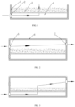
- the breeding platform includes bottom sealing layer 4 and a plurality of insect breeding layers 9.
- one insect breeding layer 9 is shown.
- the insect breeding layer 9 includes a breathable support plate 3 and baffle 1 provided around the breathable support plate 3.
- the air drying system includes drying air inlet 2 provided below the breathable support plate 3.
- the drying air inlet 2 is connected to an inlet of hot air duct 18.
- the hot air duct 18 is configured to provide dry hot air with an air drying effect.
- An upper part of the breeding platform is not provided with any upper cover 6, and the breeding platform offers open breeding.
- This breeding method is extensive and not conducive to regulating the breeding environment.
- An operation process of this embodiment is as follows.
- the drying air inlet 2 is closed, and open breeding is carried out. After the breeding is completed, the drying air inlet 2 is opened for drying with the dry hot air.
- the dry hot air enters from a lower part of the breathable support plate 3 to dry the insect larvae and frass on the insect breeding layer 9.
- the larvae are heated and flip in the residual feed, playing a role in loosening, flipping, and stirring the materials, greatly improving the air drying efficiency.
- this embodiment is basically the same as Embodiment 1, with the following differences.
- the upper part of the breeding platform is provided with the upper cover 6, and the upper cover 6 can be opened for charging and discharging operations.
- the upper cover 6 is directly pressed onto the baffle 1 to achieve a sealing effect through its own gravity.
- the upper cover 6 and the baffle 1 can also be flexibly mounted together in other ways to achieve the sealing effect.
- the upper cover 6 changes the entire breeding platform into a sealed whole, facilitating precise control of the breeding environment and improving breeding efficiency.
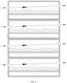
- the breeding and air drying system further includes a ventilation system.
- the ventilation system includes breeding air inlet 5 provided above or below the breathable support plate 3 and air outlet 7 provided above the breathable support plate 3.
- the breeding air inlet 5 is connected to breeding air inlet duct 15.
- the breeding air inlet duct is configured to provide a gas for controlling the temperature, humidity, and oxygen content of the breeding space.
- An operation process of this embodiment is as follows. As shown in FIG. 2 , during normal breeding, the breeding air inlet 5 is opened, and the drying air inlet 2 is closed.
- the breeding air inlet duct provides the gas for controlling the temperature, humidity, and oxygen content of the breeding space, so as to control the breeding environment.
- FIG. 3 when air drying is needed, the breeding air inlet 5 is closed, and the drying air inlet 2 is opened.
- the dry hot air enters from the lower part of the breathable support plate 3 to dry the insect larvae and frass on the insect breeding layer 9.
- the structure of this embodiment can be taken as a whole for multi-layer breeding to improve the breeding density.
- this embodiment is basically the same as Embodiment 1, with the following differences.
- the upper part of the breeding platform is provided with the upper cover 6, and the upper cover 6 can be opened for charging and discharging operations.
- the breeding and air drying processes of this embodiment are basically the same as those described in the above embodiment, with the following differences.
- there are two layers for simultaneous air drying specifically, third and fourth layers for simultaneous air drying.
- first, fifth, and sixth layers carry out normal ventilation for the breeding operation.
- the breeding air inlets 5 on the second to fourth layers and the air outlets 7 on the second and third layers are closed.
- the drying air inlet 2 on the second layer is opened, so the dry hot air enters from the drying air inlet on the second layer.
- the larvae on the second layer get in the material to avoid high-temperature damage.
- the dry hot air passes through the third and fourth layers and is discharged from the air outlet 7 of the fourth layer to dry the larvae and frass.
- Embodiments 2 and 3 both provide multiple layers for breeding, but during the charging and discharging process, it is necessary to move the insect breeding layers 9, which is a complex operation.
- This embodiment provides a breeding and air drying system for a saprophagous insect.
- the breeding and air drying system can achieve breeding and air drying operations, and includes a breeding platform and an air drying system.
- the breeding platform includes bottom sealing layer 4 and a plurality of insect breeding layers 9.
- the insect breeding layer 9 includes a breathable support plate 3 and baffle 1 provided around the breathable support plate 3.
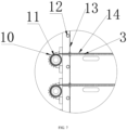
- the insect breeding layer 9 further includes support fabric 14, left roller 11, right roller 26, and roller power mechanisms 22.
- the baffle 1 includes front baffle 24, rear baffle 17, left baffle 13, and right baffle 28.
- the support fabric 14 is in contact with the breathable support plate 3. Two ends of the support fabric 14 are respectively wound around the left roller 11 and the right roller 26.
- the left roller 11 and the right roller 26 are fixed to frame 8.
- the left roller 11 and the right roller 26 are respectively connected to the roller power mechanisms 22.
- the roller power mechanisms 22 are respectively configured to drive the left roller 11 and the right roller 26 to rotate.
- the left baffle 13 and/or the right baffle 28 are movable structures that can be opened and closed. When the left baffle 13 and right baffle 28 are closed, the support fabric 14 and the breathable support plate 3 are tightly sealed.
- the left baffle 13 and/or the right baffle 28 each are fixed to the frame 8 through rotating shaft 12.
- the rotating shaft 12 is connected to rotating shaft 12 power mechanism.
- the left baffle 13 is a movable structure
- the right baffle 28 is a fixed structure.
- the rotating shaft 12 power mechanism is configured to drive the opening and closing of the baffle.
- the rotating shaft power mechanism can be a power device in the prior art, such as a hydraulic cylinder, and in this embodiment, it is micro motor 19.
- the roller power mechanism 22 is configured to drive the roller to rotate and achieve the wind-up and wind-off of the support fabric 14. Power motors with automatic clutches, or servo motors, can be mounted at two ends of each layer. However, such a structure makes a bulky device and high cost.
- the roller power mechanism 22 includes linear guide rail 29, guide rail motor 32, roller motor 30, driven gear 10 provided at an end of the roller, and driving gear 31 provided at an end of the roller motor 30.
- the roller motor 30 is fixed to a slider of the linear guide rail 29.
- the guide rail motor 32 drives the linear guide rail 29 to move. During operation, the guide rail motor 32 drives the slider to move in a straight line, which in turn drives the roller motor 30 to move to a roller desired to move.
- the driven gear 10 at an end of the roller meshes with the driving gear 31 at an end of the roller motor 30.
- the guide rail motor 32 stops moving, and the roller motor 30 is started to drive the roller to rotate for the wind-up and wind-off of the support fabric 14.
- the air drying system includes drying air inlet 2 provided below the breathable support plate 3.
- the drying air inlet 2 is connected to an inlet of hot air duct 18.
- the hot air duct 18 is configured to provide dry hot air with an air drying effect.
- a top of the breeding platform is provided with the upper cover 6.
- the breeding and air drying system further includes a ventilation system.
- the ventilation system includes breeding air inlet 5 provided above or below the breathable support plate 3 and air outlet 7 provided above the breathable support plate 3.
- the breeding air inlet 5 is connected to breeding air inlet duct 15.
- the breeding air inlet duct is configured to provide a gas for controlling the temperature, humidity, and oxygen content of the breeding space.
- the air outlet 7 is provided on an upper part of the breathable support plate 3.
- the breeding air inlet 5, the air outlet 7, and the drying air inlet 2 are provided according to actual needs. For example, they are provided at each layer, at every other layer, or at two sides. In order to achieve precise control of breeding and air drying, the following solution is adopted in this embodiment. Except for the top insect breeding layer, each of the other insect breeding layers 9 is provided with the breeding air inlet 5, the air outlet 7, and the drying air inlet 2.
- the breeding air inlet duct 15 is provided with breeding air inlet valve 25.
- An air outlet duct is provided with an air outlet valve.
- the hot air duct 18 is provided with dry hot air inlet valve 23.
- the breeding air inlet 5 and the drying air inlet 2 are provided at two sides in one direction of the system, and two air outlets 7, namely a breeding air outlet and a drying air outlet, are provided at two sides in the other direction of the system.
- the breeding air outlet is provided on the breeding air outlet duct 20, and breeding air outlet valve 21 is provided on the breeding air outlet duct 20.
- the drying air outlet is provided on drying air outlet duct 16, and drying air outlet valve 27 is provided on the drying air outlet duct 16.
- the breeding air outlet valve 21 is opened, and the drying air outlet valve 27 is closed.
- the breeding air inlet valve is opened, and the breeding air outlet valve 21 is closed.
- the breeding air inlet 5 and the drying air inlet 2 are provided at the same side in one direction of the system, and one air outlet is provided at one side in the other direction of the system.
- the breeding and air drying system further includes a temperature and humidity sensor and a control system.
- the breeding air inlet valve 25 and the hot air inlet valve are electric valves.
- the breeding air inlet valve 25 and the hot air inlet valve are connected to the control system, respectively.
- the temperature and humidity sensor is provided at the air outlet.
- the temperature and humidity sensor and another sensor such as a dissolved oxygen sensor (not shown in the figure) can be provided on the insect breeding layer 9, which is a conventional configuration.
- the sensor can be mounted in any appropriate position as needed to control the breeding environment.
- the temperature and humidity sensor is mounted at the air outlet to measure the temperature and humidity of the air outlet during air drying.
- the valve at the air outlet is closed, allowing the hot air to continue to flow upwards and be discharged from the above air outlet, thereby achieving the purpose of fully utilizing heat.
- the control system is a programmable microcontroller or programmable logic controller (PLC).
- PLC programmable logic controller
- the control system is a programmable microcontroller.
- the charging and discharging processes of this embodiment are as follows.
- the charging process is as follows.
- the control system controls the rotating shaft 12 power mechanism to open the left baffle 13 of the insect breeding layer, and a charging port of a charging mechanism extends into the insect breeding layer 9.
- the guide rail motor 32 drives the slider to move in a straight line, which in turn drives the roller motor 30 to move to the right roller 26 desired to move.
- the driven gear 10 at one end of the right roller 26 meshes with the driving gear 31 at an end of the roller motor 30.
- the guide rail motor 32 stops moving, and the roller motor 30 is started to drive the roller to rotate for the wind-up and wind-off of the support fabric 14.
- the charging mechanism moves to transport the material to the support fabric 14.
- the support fabric 14 is driven by the roller to move to the right and transports the material from left to right. In this way, the support fabric moves while spreading the material, thereby completing the material spreading operation.
- the discharging process is as follows.
- the control system controls the rotating shaft 12 power mechanism to open the left baffle 13 of the insect breeding layer, and a charging port of a discharging mechanism extends into the insect breeding layer 9.
- the guide rail motor 32 drives the slider to move in a straight line, which in turn drives the roller motor 30 to move to the left roller 11 desired to move.
- the driven gear 10 at one end of the left roller 11 meshes with the driving gear 31 at an end of the roller motor 30.
- the guide rail motor 32 stops moving, and the roller motor 30 is started to drive the roller to rotate for the wind-up and wind-off of the support fabric 14.
- the material is collected from the support fabric 14 and enters the discharging mechanism through the discharging port, thereby completing the discharge.
- the left baffle and the right baffle are movable structures, and the charging mechanism and the discharging mechanism are respectively provided at two ends of the breeding platform to achieve simultaneous charging and discharging operations, effectively improving device utilization.
- This embodiment provides a breeding and air drying method for a saprophagous insect, implemented by the breeding and air drying system for a saprophagous insect in Embodiment 5, and including the following steps.
- step (2) an intermittent air drying mode is used. Specifically, air-drying is carried out for a period of time and paused for a period of time, and air-drying and pausing are repeated. During air drying, mature larvae flip from a lower layer to an upper layer, while during pausing, mature larvae flip from the upper layer to the lower layer. The air-drying and the pausing are repeated to loosen and flip the material on the air-dried insect breeding layer, thereby improving breathability and air drying efficiency.
- the dry hot air is high-pressure dry hot air.
- the pressure of the high-pressure dry hot air needs to be higher than an external pressure of the breeding and air drying system.
- a higher pressure is more conducive to the flow of the dry hot air.
- an excessive pressure can lead to an increase in the air drying cost, so the pressure is generally set according to an actual need.
- test materials were collected when the larvae of Hermetia illucens were bred for 10 days, which had a moisture content of 61.6% and were composed of the larvae and frass with a ratio of 1:2. Each drying method was tested 5 times, using 100 kg of materials.
- Drying method 1 The larvae and the frass were not separated, but were directly dried by a roller dryer to a moisture content of 25%. Then the larvae and the frass were separated by screening, and an energy consumption and a larvae yield were calculated.
- Embodiment 2 The single-layer structure of Embodiment 2 was adopted.
- the insect breeding layer 9 had an area of 5 m2, and 100 kg of materials were evenly spread on the insect breeding layer 9.
- Continuous air drying was carried out at 47°C and 1,210 pa until the larvae and frass were dried to a 25% moisture content. An energy consumption and a larvae yield were calculated.
- Embodiment 3 The single-layer structure of Embodiment 2 was adopted.
- the insect breeding layer 9 had an area of 5 m2, and 100 kg of materials were evenly spread on the insect breeding layer 9.
- Intermittent air drying was carried out. Specifically, air drying was carried out at 47°C and 1,210 pa for 3 min, and was paused for 2 min. The air drying and pausing were repeated until the frass and larvae were dried to a 25% moisture content. An energy consumption and a larvae yield were calculated.
- the test data are shown in the table below.
- the method of the present disclosure significantly increases the larvae yield by more than 12%. Therefore, the device and method of the present disclosure have obvious advantages in the breeding and air drying of hermetia illucens larvae.
- one breeding layer is shown, and there is no sealing device above or below the insect breeding layer.
- upper and lower sealing layers can be provided, and multiple breeding layers as shown in this embodiment can be provided.
- An operation process of this embodiment is as follows.
- the spreading process is as follows.
- the left baffle and the right baffle are opened, and the spreading roller 33 rotates, driving the support fabric to move.
- the material moves continuously with the support fabric, thus being transported from one end of the insect breeding layer to the other end.
- the support fabric wound around the spreading roller 33 is not contaminated by the material.
- the collection process is as follows. At the end of breeding, the collection roller moves and drives the support fabric to move, allowing the material to be transported from one end of the insect breeding layer to the other end thereof. The material detaches from the support fabric under the action of gravity, thereby completing the material collection operation. During this process, the support fabric wound around the collection roller is located under the support fabric contaminated with the material, and is thus not contaminated by the material.
- the support fabric wound around the spreading roller 33 and the collection roller are not contaminated with the material and are clean. Therefore, during the wind-up and wind-off process, the support fabric is uniform without deviation, ensuring even and labor-saving spreading and collection and effectively extending the service life of the device.
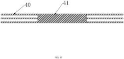
- the support fabric can be a one-piece breathable fabric, plastic mesh, or metal mesh.
- the support fabric can adopt the following structure.
- the support fabric includes a plurality of pull ropes 40 provided at two ends of the support fabric and having the same length as the insect breeding layer and fabric belt 41 provided at a middle.
- a width of the fabric belt 41 is the same as a width of the insect breeding layer.
- the structure can effectively reduce the friction force between the support fabric and the spreading roller 33 as well as the collection roller, and effectively reduce energy consumption.
- the support fabric can include one end provided with the pull ropes and the other end provided with the fabric belt.
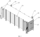
- a breeding and spreading device for a saprophagous insect includes multiple breeding layers and a frame.
- the insect breeding layer includes a breathable support plate and a baffle provided around the breathable support plate.
- the baffle includes a front baffle, a rear baffle, a left baffle, and a right baffle.
- the left baffle and/or the right baffle are respectively fixed to the frame through a rotating shaft, and the rotating shaft is connected to a rotating shaft power mechanism.
- the right baffle is fixed to the frame through the rotating shaft, which is connected to the rotating shaft power mechanism (generally electric push rod 37, which is not shown in the figure).
- the left baffle is fixed to the frame.
- a lower part of the left baffle is at a certain distance from the support fabric, and a left side is sealed by the gravity of the material.
- the right baffle is opened under the action of the rotating shaft power mechanism, so as to carry out the spreading and collection operations.
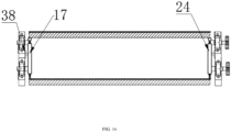
- Each of the front baffle and the rear baffle is provided in sliding groove 38 of the frame through slider 39.
- Each of the front baffle and the rear baffle includes an upper end provided with an upper elastic sealing mechanism and a lower end provided with a lower elastic sealing mechanism.
- An end of each of the front baffle and the rear baffle is connected to a sliding power mechanism.
- the upper elastic sealing mechanism is in contact with the breathable support plate of an upper insect breeding layer that is adjacent to and in contact with the insect breeding layer.
- the lower elastic sealing mechanism is in contact with the breathable support plate.
- the sliding power mechanism drives the front baffle and the rear baffle to move obliquely upwards to separate the lower elastic sealing mechanism from the breathable support plate.
- the upper elastic sealing mechanism keeps in contact with the breathable support plate of the upper insect breeding layer that is adjacent to and in contact with the insect breeding layer.
- the upper elastic sealing mechanism includes connecting plate 43 and large elastic tube 42.
- the connecting plate 43 includes one end provided on the front baffle or the rear baffle and the other end fixed to the large elastic tube 42.
- the lower elastic sealing mechanism includes connecting plate 43 and small elastic tube 44.
- the connecting plate 43 includes one end provided on the front baffle or the rear baffle and the other end fixed to the small elastic tube 44.
- the sliding power mechanism includes electric push rod 37.
- the electric push rod 37 includes one end fixed to the frame and the other end fixed to the front baffle or the rear baffle through a connecting mechanism.
- the left baffle and the right baffle are generally long and require a small distance of movement, usually less than 1 cm. If a vertical tension is used, there is a problem of stress imbalance. Therefore, in the present disclosure, the slide way is generally tilted 3-10°. In this way, at one end of the left baffle and the right baffle, an obliquely upwards pull is applied to move the left baffle and the right baffle up and down. The design ensures stress balance and smooth operation of the left baffle and the right baffle.
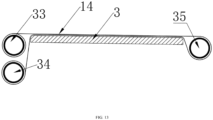
- the insect breeding layer includes one end provided with inert roller 35 and the other end provided with spreading roller 33 and larvae collection roller 34.
- the spreading roller 33 is provided above the larvae collection roller 34.
- the spreading roller 33 and the larvae collection roller 34 are provided with a driving mechanism.
- the support fabric includes one end fixed to the spreading roller 33 and the other end bypassing the inert roller 35 and fixed to the larvae collection roller 34.
- a length of the support fabric is three times a length of the insect breeding layer.
- the spreading roller 33 is wound with one part of the support fabric with the same length as the insect breeding layer, and the remaining part of the support fabric is fixed between the spreading roller 33, the inert roller 35, and the larvae collection roller 34.
- An operation process of this embodiment is as follows.
- the left baffle and the right baffle compress edges of the support fabric onto the breathable support plate.
- the electric push rod 37 drives the left baffle and the right baffle obliquely upwards.
- the small elastic tube 44 leaves the support fabric, and the large elastic tube 42 is compressed. In this way, during the distribution and collection processes, the edges of the support fabric are evenly stressed, and all materials can be transported, ensuring complete material collection.
- collection devices can be provided at two sides of the breathable support plate to collect the escaping larvae.
- the structure of the collection device is designed as needed, as shown in FIG. 18 .
- the two sides of the breathable support plate are provided with slotted collection pipes 45. The structure allow the escaping larvae to automatically fall into the collection pipes 45 for unified collection, thereby effectively avoiding the problem of larvae escaping.
Landscapes
- Life Sciences & Earth Sciences (AREA)
- Environmental Sciences (AREA)
- Animal Husbandry (AREA)
- Zoology (AREA)
- Animal Behavior & Ethology (AREA)
- Biodiversity & Conservation Biology (AREA)
- Chemical & Material Sciences (AREA)
- Engineering & Computer Science (AREA)
- Polymers & Plastics (AREA)
- Biomedical Technology (AREA)
- Molecular Biology (AREA)
- Food Science & Technology (AREA)
- Health & Medical Sciences (AREA)
- Biotechnology (AREA)
- Physiology (AREA)
- Housing For Livestock And Birds (AREA)
- Drying Of Solid Materials (AREA)
- Catching Or Destruction (AREA)
Claims (9)
- Zucht- und Lufttrocknungssystem für ein saprophages Insekt, das ausgelegt ist, um Zucht- und Lufttrocknungsvorgänge durchzuführen, und das eine Zuchtplattform, ein Belüftungssystem und ein Lufttrocknungssystem umfasst, wobei eine Oberseite der Zuchtplattform mit einer oberen Abdeckung (6) versehen ist, die Zuchtplattform eine unterseitige Abdichtungsschicht (4) und eine Vielzahl von Insektenzuchtschichten (9) umfasst, wobei eine jede Insektenzuchtschicht (9) eine atmungsaktive Trägerplatte (3) und eine Trennwand (1) umfasst, die rund um die atmungsaktive Trägerplatte (3) bereitgestellt ist, wobei das Belüftungssystem einen Zuchtlufteinlass (5) umfasst, der über oder unter der atmungsaktiven Trägerplatte (3) bereitgestellt ist, wobei der Zuchtlufteinlass (5) mit einer Zuchtlufteinlassleitung (15) verbunden ist und wobei die Zuchtlufteinlassleitung (15) ausgelegt ist, um ein Gas zur Regelung einer Temperatur, einer Feuchtigkeit und eines Sauerstoffgehalts eines Zuchtraums bereitzustellen,dadurch gekennzeichnet, dass das Lufttrocknungssystem einen Trocknungslufteinlass (2) umfasst, der unter der atmungsaktiven Trägerplatte (3) bereitgestellt ist, der Trocknungslufteinlass (2) mit einem Einlass einer Heißluftleitung (18) verbunden ist und die Heißluftleitung (18) ausgelegt ist, um trockene heiße Luft mit einem Lufttrocknungseffekt bereitzustellen;dadurch, dass das Belüftungssystem zudem einen Luftauslass (7) umfasst, der über der atmungsaktiven Trägerplatte (3) bereitgestellt ist, und dadurch, dassjede der Insektenzuchtschichten (9) mit Ausnahme einer oberseitigen Insektenzuchtschicht (9) mit dem Zuchtlufteinlass (5), dem Luftauslass (7) und dem Trocknungslufteinlass (2) versehen ist, die Zuchtlufteinlassleitung (15) mit einem Zuchtlufteinlassventil (25) versehen ist, eine Luftauslassleitung mit einem Luftauslassventil versehen ist und die Heißluftleitung (18) mit einem Trockenheißlufteinlassventil (23) versehen ist.
- Zucht- und Lufttrocknungssystem für das saprophage Insekt nach Anspruch 1, wobei das Zucht- und Lufttrocknungssystem zudem ein Steuersystem umfasst und das Zuchtlufteinlassventil (25) und das Heißlufteinlassventil elektrische Ventile sind und das Zuchtlufteinlassventil (25) und das Heißlufteinlassventil jeweils mit dem Steuersystem verbunden sind.
- Zucht- und Lufttrocknungssystem für das saprophage Insekt nach Anspruch 1 oder 2, wobei am Luftauslass (7) ein Temperatur- und Feuchtigkeitssensor bereitgestellt ist.
- Zucht- und Lufttrocknungssystem für das saprophage Insekt nach Anspruch 1 oder 2, wobei die Insektenzuchtschicht (9) zudem ein Trägergewebe (14) oder Trägernetz, eine linke Walze (11), eine rechte Walze (26) und einen Walzenantriebsmechanismus (22) umfasst, die Trennwand (1) eine vordere Trennwand (24), eine hintere Trennwand (17), eine linke Trennwand (13) und eine rechte Trennwand (28) umfasst, das Trägergewebe (14) mit der atmungsaktiven Trägerplatte (3) in Kontakt ist, zwei Enden des Trägergewebes (14) jeweils um die linke Walze (11) und die rechte Walze (26) gewunden sind, die linke Walze (11) und die rechte Walze (26) an einem Rahmen (8) befestigt sind, die linke Walze (11) und die rechte Walze (26) jeweils mit dem Walzenantriebsmechanismus (22) verbunden sind, der Walzenantriebsmechanismen (22) jeweils ausgelegt ist, um die linke Walze (11) und die rechte Walze (26) in Drehung zu versetzen, die linke Trennwand (13) und/oder die rechte Trennwand (28) bewegliche Strukturen sind, die ausgelegt sind, um geöffnet und geschlossen zu werden, und das Trägergewebe (14) und die atmungsaktive Trägerplatte (3) fest abgedichtet sind, wenn die linke Trennwand (13) und die rechte Trennwand (28) geschlossen sind.
- Zucht- und Lufttrocknungssystem für das saprophage Insekt nach Anspruch 4, wobei der Walzenantriebsmechanismus (22) eine lineare Führungsschiene (29), einen Führungsschienenmotor (32), einen Walzenmotor (30), ein Abtriebsrad (10), das an einem Ende der Walze bereitgestellt ist, und ein Antriebsrad (31), das an einem Ende des Walzenmotors (30) bereitgestellt ist, umfasst, der Walzenmotor (30) an einem Schieber (39) der linearen Führungsschiene (29) befestigt ist und der Führungsschienenmotor (32) den Schieber (39) antreibt, sodass sich dieser linear bewegt.
- Zucht- und Lufttrocknungssystem für das saprophage Insekt nach Anspruch 4, wobei die linke Trennwand (13) und/oder die rechte Trennwand (28) durch eine rotierende Welle (12) am Rahmen (8) befestigt sind und die rotierende Welle (12) mit einem Antriebsmechanismus der rotierenden Welle verbunden ist.
- Zucht- und Lufttrocknungsverfahren für ein saprophages Insekt, das durch das Zucht- und Lufttrocknungssystem für das saprophage Insekt nach einem der Ansprüche 1 bis 6 umgesetzt wird und die folgenden Schritte umfasst:(1) Positionieren von Larven des saprophagen Insekts und eines Futters zusammen auf der Insektenzuchtschicht (9) und Regeln eines Temperatur-, Feuchtigkeits- und Sauerstoffgehalts, der für die Zucht des saprophagen Insekts erforderlich ist;(2) wenn an einem Ende der Zucht eine Lufttrocknung erforderlich ist: Schließen des Zuchtlufteinlasses (5) einer Insektenzuchtschicht (9), die Lufttrocknung benötigt, und des Zuchtlufteinlasses (5) einer angrenzenden Insektenzuchtschicht (9) darunter, Schließen des Luftauslasses (7) der angrenzenden Insektenzuchtschicht (9) darunter und Öffnen des Trocknungslufteinlasses (2) der angrenzenden Insektenzuchtschicht (9) darunter, sodass die trockene heiße Luft durch die Insektenzuchtschicht (9) strömt, die Lufttrocknung benötigt, und aus dem Luftauslass (7) der Insektenzuchtschicht (9), die Lufttrocknung benötigt, ausströmt, wodurch eine In-situ-Lufttrocknung eines Restfutters und der Larven erreicht wird, und(3) Zulassen, dass die Larven während der Lufttrocknung erwärmt werden und in das Restfutter gewendet werden, und Eingreifen beim Lockern, Wenden und Rühren eines Materials, wodurch eine Lufttrocknungseffizienz erheblich verbessert wird.
- Zucht- und Lufttrocknungsverfahren für das saprophage Insekt nach Anspruch 7, wobei in Schritt 2 ein intermittierender Lufttrocknungsmodus verwendet wird, bestehend aus: Lufttrocknung für einen bestimmten Zeitraum, Pausieren für einen bestimmten Zeitraum und Wiederholen der Lufttrocknung und des Pausierens, wobei während der Lufttrocknung reife Larven von einer unteren Schicht in eine obere Schicht wechseln, während die reifen Larven während des Pausierens von der oberen Schicht zur unteren Schicht wechseln, und Wiederholen der Lufttrocknung und des Pausierens, wobei das Material auf der luftgetrockneten Insektenzuchtschicht (9) gelockert und gewendet wird, wodurch die Atmungsaktivität und die Lufttrocknungseffizienz verbessert werden.
- Zucht- und Lufttrocknungsverfahren für das saprophage Insekt nach Anspruch 7 oder 8, wobei die trockene heiße Luft trockene Hochdruck-Heißluft ist.
Applications Claiming Priority (2)
| Application Number | Priority Date | Filing Date | Title |
|---|---|---|---|
| CN202111347392.5A CN115251011B (zh) | 2021-11-15 | 2021-11-15 | 一种腐食性昆虫养殖风干系统及其方法 |
| PCT/CN2022/131266 WO2023083278A1 (zh) | 2021-11-15 | 2022-11-11 | 一种腐食性昆虫养殖风干系统及其方法 |
Publications (4)
| Publication Number | Publication Date |
|---|---|
| EP4364558A1 EP4364558A1 (de) | 2024-05-08 |
| EP4364558A4 EP4364558A4 (de) | 2024-10-02 |
| EP4364558B1 true EP4364558B1 (de) | 2025-04-09 |
| EP4364558C0 EP4364558C0 (de) | 2025-04-09 |
Family
ID=83758236
Family Applications (1)
| Application Number | Title | Priority Date | Filing Date |
|---|---|---|---|
| EP22892071.6A Active EP4364558B1 (de) | 2021-11-15 | 2022-11-11 | Lufttrocknungssystem zur züchtung saprophagen insekten und verfahren dafür |
Country Status (4)
| Country | Link |
|---|---|
| US (1) | US12178197B2 (de) |
| EP (1) | EP4364558B1 (de) |
| CN (1) | CN115251011B (de) |
| WO (1) | WO2023083278A1 (de) |
Families Citing this family (4)
| Publication number | Priority date | Publication date | Assignee | Title |
|---|---|---|---|---|
| CN115251011B (zh) * | 2021-11-15 | 2023-07-07 | 郑州笨农农业科技有限公司 | 一种腐食性昆虫养殖风干系统及其方法 |
| EP4512244A1 (de) * | 2023-08-22 | 2025-02-26 | Nasekomo B.V. | Automatisierte anlage zur insektenzucht |
| CN117918310A (zh) * | 2024-01-23 | 2024-04-26 | 安徽天康(集团)股份有限公司 | 一种利用皇粉虫无害化餐厨物的生物养殖装置及方法 |
| CN118805743A (zh) * | 2024-06-06 | 2024-10-22 | 郑州尧安环保科技有限公司 | 一种立体昆虫养殖平台的节能通风装置 |
Family Cites Families (33)
| Publication number | Priority date | Publication date | Assignee | Title |
|---|---|---|---|---|
| US5178094A (en) * | 1990-05-02 | 1993-01-12 | Crop Genetics International Corporation | Method and apparatus for mass producing insects entomopathogens and entomoparasites |
| US6342499B1 (en) * | 1998-07-14 | 2002-01-29 | Basf Aktiengesellschaft | Parasitic and saprophagous mite control in beneficial insects |
| US6474259B1 (en) * | 2001-04-30 | 2002-11-05 | Rutgers, The State University Of New Jersey | Apparatus and method for mass production of insecticidal nematodes |
| JP5582560B2 (ja) * | 2008-11-04 | 2014-09-03 | 株式会社Bbb | 昆虫育成堆肥床 |
| US20110139075A1 (en) * | 2009-12-11 | 2011-06-16 | Shapiro Ilan David I | System and Method for Production of Predatory Mites |
| US9010019B2 (en) * | 2010-03-16 | 2015-04-21 | Marc A. Mittelmark | Plant air purification enclosure apparatus and method |
| WO2012115959A2 (en) * | 2011-02-21 | 2012-08-30 | The University Of Georgia Research Foundation, Inc. | Systems and methods for rearing insect larvae |
| CN202792856U (zh) * | 2012-07-05 | 2013-03-13 | 浙江省长三角循环经济技术研究院 | 昆虫干燥机 |
| JP5913044B2 (ja) * | 2012-10-26 | 2016-04-27 | 株式会社イーズ | 有機肥料及び飼料製造システム |
| NL2010666B3 (en) * | 2013-04-19 | 2018-11-21 | Buhler Changzhou Insect Tech Co Ltd | Method and system for breeding insects, using a plurality of individual crates. |
| CN203709071U (zh) | 2014-01-22 | 2014-07-16 | 广州飞禧特水产科技有限公司 | 黑水虻养殖平台、多层式养殖装置及主动通风式养殖装置 |
| CN103884159B (zh) * | 2014-03-19 | 2016-04-20 | 广东省昆虫研究所 | 一种食用/药用/饲用昆虫的干燥设备 |
| US20150305320A1 (en) * | 2014-04-24 | 2015-10-29 | Thermapure, Inc. | Process for heat treating buildings and articles |
| JP6360724B2 (ja) * | 2014-06-05 | 2018-07-18 | 豊田興産株式会社 | 有機性廃棄物の乾燥装置 |
| CN105300073B (zh) * | 2015-07-16 | 2017-12-29 | 江苏丰尚智能科技有限公司 | 一种带式干燥机 |
| CN206213054U (zh) * | 2016-11-29 | 2017-06-06 | 小肥虫生物科技有限公司 | 一种黑水虻幼虫量产养殖装置 |
| CN206751634U (zh) | 2017-03-08 | 2017-12-15 | 广东益康生环保设备有限公司 | 一种高效节能的粪便风干设备 |
| CN107873648A (zh) * | 2017-11-23 | 2018-04-06 | 广州飞禧特生物科技有限公司 | 黑水虻幼虫养殖收集设备及方法 |
| CN208332897U (zh) * | 2018-05-17 | 2019-01-04 | 江门市山海堂虫草有限公司 | 一种蛹虫草烘干装置 |
| CN210045537U (zh) * | 2019-01-10 | 2020-02-11 | 河南恩赛姆生物科技有限公司 | 一种黑水虻幼虫养殖筛分干燥设备 |
| CN209877548U (zh) * | 2019-03-16 | 2019-12-31 | 河北丰康农业科技股份有限公司 | 一种滚筒式黄粉虫烘干装置 |
| CN109984095A (zh) * | 2019-04-18 | 2019-07-09 | 扬州宇家环保科技有限公司 | 一种黑水虻全自动养殖装置 |
| CN210226597U (zh) | 2019-06-14 | 2020-04-03 | 郑州笨农农业科技有限公司 | 黑水虻养殖装置 |
| CN112715486B (zh) | 2019-10-28 | 2022-09-20 | 蜻蜓创意有限公司 | 一种连续自动化生物反应器 |
| CN111202031A (zh) * | 2020-02-14 | 2020-05-29 | 坎布里奇环保科技(北京)有限公司 | 一种黑水虻幼虫养殖装置、方法 |
| CN213187729U (zh) | 2020-03-31 | 2021-05-14 | 简阳洁城环保科技有限公司 | 一种黑水虻养殖装置 |
| CN212987947U (zh) * | 2020-08-25 | 2021-04-16 | 源创环境科技有限公司 | 一种节能型黑水虻虫干制备装置 |
| IT202100001571A1 (it) * | 2021-01-27 | 2022-07-27 | Smartgrubs Srlu | Dispositivo intelligente per il compostaggio di rifiuti organici mediante l’utilizzo di larve di insetti saprofagi e procedimento per il monitoraggio della bioconversione. |
| CN112931421B (zh) * | 2021-03-17 | 2023-05-23 | 河南迈安达生物安全技术有限公司 | 一种高密度昆虫饲养机构、装置及其系统 |
| TWM624958U (zh) * | 2021-03-19 | 2022-04-01 | 蜻蜓創意有限公司 | 塔形連續自動化生物飼養器 |
| CN113057145B (zh) * | 2021-03-30 | 2023-06-20 | 浙江科技学院 | 一种节能环保的全封闭式黑水虻自动养殖方法 |
| CN113317283B (zh) * | 2021-06-23 | 2023-04-25 | 郑州笨农农业科技有限公司 | 一种立体黑水虻养殖机构、养殖系统和养殖方法 |
| CN115251011B (zh) | 2021-11-15 | 2023-07-07 | 郑州笨农农业科技有限公司 | 一种腐食性昆虫养殖风干系统及其方法 |
-
2021
- 2021-11-15 CN CN202111347392.5A patent/CN115251011B/zh active Active
-
2022
- 2022-11-11 WO PCT/CN2022/131266 patent/WO2023083278A1/zh not_active Ceased
- 2022-11-11 US US18/291,581 patent/US12178197B2/en active Active
- 2022-11-11 EP EP22892071.6A patent/EP4364558B1/de active Active
Also Published As
| Publication number | Publication date |
|---|---|
| US12178197B2 (en) | 2024-12-31 |
| EP4364558A4 (de) | 2024-10-02 |
| CN115251011A (zh) | 2022-11-01 |
| EP4364558C0 (de) | 2025-04-09 |
| WO2023083278A1 (zh) | 2023-05-19 |
| US20240260554A1 (en) | 2024-08-08 |
| EP4364558A1 (de) | 2024-05-08 |
| CN115251011B (zh) | 2023-07-07 |
Similar Documents
| Publication | Publication Date | Title |
|---|---|---|
| EP4364558B1 (de) | Lufttrocknungssystem zur züchtung saprophagen insekten und verfahren dafür | |
| CN103004977A (zh) | 一种可换向通风的箱式干燥机及对粮油作物干燥的方法 | |
| CN112005933B (zh) | 一种封盖蜂蜜后熟装置及其操作方法 | |
| CN111664657A (zh) | 一种热泵干燥室 | |
| CN113632833A (zh) | 一种基于石墨烯远红外加热的粮食循环干燥机及其干燥方法 | |
| CN206583238U (zh) | 一种可变风向的多通道混流干燥箱 | |
| CN203327867U (zh) | 一种可换向通风的箱式干燥机 | |
| CN112577293A (zh) | 一种分层控温控时的多层网带式油茶籽干燥装置 | |
| CN110608598A (zh) | 一种玉米穗粒联动干燥生产线 | |
| CN106679393B (zh) | 一种粮食烘干系统 | |
| CN201081531Y (zh) | 一种新型烘干设备 | |
| CN209279547U (zh) | 一种可调节封闭度的敞开式竹篾干燥窑 | |
| CN207763369U (zh) | 一种模块化换向通风干燥机 | |
| CN103404631B (zh) | 一种茶叶自动化生产线 | |
| CN216192154U (zh) | 一种自动糖化设备 | |
| CN212971641U (zh) | 一种提高烟草醇化质量的装置 | |
| CN114747639A (zh) | 一种箱式茶叶闷黄机 | |
| CN208504907U (zh) | 一种新型种子干燥装置 | |
| CN107816851A (zh) | 一种模块化通风干燥室 | |
| CN107493720A (zh) | 一种蔬菜种子晾晒装置 | |
| CN223600951U (zh) | 一种节能型鞋子生产用烘干装置 | |
| CN113606890A (zh) | 一种基于液压辅助上卸料的多层固定干燥机 | |
| CN114674130B (zh) | 一种温度可控的高效粮食烘干机 | |
| CN220250582U (zh) | 一种烘干机 | |
| CN223435374U (zh) | 一种菊花茶真空加工设备 |
Legal Events
| Date | Code | Title | Description |
|---|---|---|---|
| STAA | Information on the status of an ep patent application or granted ep patent |
Free format text: STATUS: THE INTERNATIONAL PUBLICATION HAS BEEN MADE |
|
| PUAI | Public reference made under article 153(3) epc to a published international application that has entered the european phase |
Free format text: ORIGINAL CODE: 0009012 |
|
| STAA | Information on the status of an ep patent application or granted ep patent |
Free format text: STATUS: REQUEST FOR EXAMINATION WAS MADE |
|
| 17P | Request for examination filed |
Effective date: 20240130 |
|
| AK | Designated contracting states |
Kind code of ref document: A1 Designated state(s): AL AT BE BG CH CY CZ DE DK EE ES FI FR GB GR HR HU IE IS IT LI LT LU LV MC ME MK MT NL NO PL PT RO RS SE SI SK SM TR |
|
| A4 | Supplementary search report drawn up and despatched |
Effective date: 20240829 |
|
| RIC1 | Information provided on ipc code assigned before grant |
Ipc: A01K 67/033 20060101AFI20240826BHEP |
|
| RAP1 | Party data changed (applicant data changed or rights of an application transferred) |
Owner name: ZHENGZHOU YAO 'AN ENVIRONMENTAL PROTECTIONTECHNOLOGY CO., LTD. |
|
| REG | Reference to a national code |
Ref country code: DE Ref legal event code: R079 Free format text: PREVIOUS MAIN CLASS: A01K0067033000 Ipc: A01K0067364000 Ref country code: DE Ref legal event code: R079 Ref document number: 602022013069 Country of ref document: DE Free format text: PREVIOUS MAIN CLASS: A01K0067033000 Ipc: A01K0067364000 |
|
| GRAP | Despatch of communication of intention to grant a patent |
Free format text: ORIGINAL CODE: EPIDOSNIGR1 |
|
| STAA | Information on the status of an ep patent application or granted ep patent |
Free format text: STATUS: GRANT OF PATENT IS INTENDED |
|
| DAV | Request for validation of the european patent (deleted) | ||
| DAX | Request for extension of the european patent (deleted) | ||
| INTG | Intention to grant announced |
Effective date: 20250113 |
|
| RIC1 | Information provided on ipc code assigned before grant |
Ipc: A01K 67/364 20250101AFI20250109BHEP |
|
| GRAS | Grant fee paid |
Free format text: ORIGINAL CODE: EPIDOSNIGR3 |
|
| GRAA | (expected) grant |
Free format text: ORIGINAL CODE: 0009210 |
|
| STAA | Information on the status of an ep patent application or granted ep patent |
Free format text: STATUS: THE PATENT HAS BEEN GRANTED |
|
| AK | Designated contracting states |
Kind code of ref document: B1 Designated state(s): AL AT BE BG CH CY CZ DE DK EE ES FI FR GB GR HR HU IE IS IT LI LT LU LV MC ME MK MT NL NO PL PT RO RS SE SI SK SM TR |
|
| REG | Reference to a national code |
Ref country code: GB Ref legal event code: FG4D |
|
| REG | Reference to a national code |
Ref country code: CH Ref legal event code: EP |
|
| REG | Reference to a national code |
Ref country code: DE Ref legal event code: R096 Ref document number: 602022013069 Country of ref document: DE |
|
| REG | Reference to a national code |
Ref country code: IE Ref legal event code: FG4D |
|
| U01 | Request for unitary effect filed |
Effective date: 20250422 |
|
| U07 | Unitary effect registered |
Designated state(s): AT BE BG DE DK EE FI FR IT LT LU LV MT NL PT RO SE SI Effective date: 20250425 |
|
| U20 | Renewal fee for the european patent with unitary effect paid |
Year of fee payment: 4 Effective date: 20250904 |
|
| PG25 | Lapsed in a contracting state [announced via postgrant information from national office to epo] |
Ref country code: ES Free format text: LAPSE BECAUSE OF FAILURE TO SUBMIT A TRANSLATION OF THE DESCRIPTION OR TO PAY THE FEE WITHIN THE PRESCRIBED TIME-LIMIT Effective date: 20250409 |
|
| PG25 | Lapsed in a contracting state [announced via postgrant information from national office to epo] |
Ref country code: NO Free format text: LAPSE BECAUSE OF FAILURE TO SUBMIT A TRANSLATION OF THE DESCRIPTION OR TO PAY THE FEE WITHIN THE PRESCRIBED TIME-LIMIT Effective date: 20250709 Ref country code: GR Free format text: LAPSE BECAUSE OF FAILURE TO SUBMIT A TRANSLATION OF THE DESCRIPTION OR TO PAY THE FEE WITHIN THE PRESCRIBED TIME-LIMIT Effective date: 20250710 |
|
| PG25 | Lapsed in a contracting state [announced via postgrant information from national office to epo] |
Ref country code: PL Free format text: LAPSE BECAUSE OF FAILURE TO SUBMIT A TRANSLATION OF THE DESCRIPTION OR TO PAY THE FEE WITHIN THE PRESCRIBED TIME-LIMIT Effective date: 20250409 |
|
| PG25 | Lapsed in a contracting state [announced via postgrant information from national office to epo] |
Ref country code: HR Free format text: LAPSE BECAUSE OF FAILURE TO SUBMIT A TRANSLATION OF THE DESCRIPTION OR TO PAY THE FEE WITHIN THE PRESCRIBED TIME-LIMIT Effective date: 20250409 |
|
| PG25 | Lapsed in a contracting state [announced via postgrant information from national office to epo] |
Ref country code: RS Free format text: LAPSE BECAUSE OF FAILURE TO SUBMIT A TRANSLATION OF THE DESCRIPTION OR TO PAY THE FEE WITHIN THE PRESCRIBED TIME-LIMIT Effective date: 20250709 |
|
| PG25 | Lapsed in a contracting state [announced via postgrant information from national office to epo] |
Ref country code: IS Free format text: LAPSE BECAUSE OF FAILURE TO SUBMIT A TRANSLATION OF THE DESCRIPTION OR TO PAY THE FEE WITHIN THE PRESCRIBED TIME-LIMIT Effective date: 20250809 |
|
| PG25 | Lapsed in a contracting state [announced via postgrant information from national office to epo] |
Ref country code: SM Free format text: LAPSE BECAUSE OF FAILURE TO SUBMIT A TRANSLATION OF THE DESCRIPTION OR TO PAY THE FEE WITHIN THE PRESCRIBED TIME-LIMIT Effective date: 20250409 |
|
| PG25 | Lapsed in a contracting state [announced via postgrant information from national office to epo] |
Ref country code: CZ Free format text: LAPSE BECAUSE OF FAILURE TO SUBMIT A TRANSLATION OF THE DESCRIPTION OR TO PAY THE FEE WITHIN THE PRESCRIBED TIME-LIMIT Effective date: 20250409 |
|
| PG25 | Lapsed in a contracting state [announced via postgrant information from national office to epo] |
Ref country code: SK Free format text: LAPSE BECAUSE OF FAILURE TO SUBMIT A TRANSLATION OF THE DESCRIPTION OR TO PAY THE FEE WITHIN THE PRESCRIBED TIME-LIMIT Effective date: 20250409 |
|
| PLBE | No opposition filed within time limit |
Free format text: ORIGINAL CODE: 0009261 |
|
| STAA | Information on the status of an ep patent application or granted ep patent |
Free format text: STATUS: NO OPPOSITION FILED WITHIN TIME LIMIT |
|
| REG | Reference to a national code |
Ref country code: CH Ref legal event code: L10 Free format text: ST27 STATUS EVENT CODE: U-0-0-L10-L00 (AS PROVIDED BY THE NATIONAL OFFICE) Effective date: 20260218 |
|
| 26N | No opposition filed |
Effective date: 20260112 |