EP4512244A1 - Automatisierte anlage zur insektenzucht - Google Patents
Automatisierte anlage zur insektenzucht Download PDFInfo
- Publication number
- EP4512244A1 EP4512244A1 EP23192781.5A EP23192781A EP4512244A1 EP 4512244 A1 EP4512244 A1 EP 4512244A1 EP 23192781 A EP23192781 A EP 23192781A EP 4512244 A1 EP4512244 A1 EP 4512244A1
- Authority
- EP
- European Patent Office
- Prior art keywords
- air
- containers
- substrate
- larvae
- container
- Prior art date
- Legal status (The legal status is an assumption and is not a legal conclusion. Google has not performed a legal analysis and makes no representation as to the accuracy of the status listed.)
- Pending
Links
Images


Classifications
-
- A—HUMAN NECESSITIES
- A01—AGRICULTURE; FORESTRY; ANIMAL HUSBANDRY; HUNTING; TRAPPING; FISHING
- A01K—ANIMAL HUSBANDRY; AVICULTURE; APICULTURE; PISCICULTURE; FISHING; REARING OR BREEDING ANIMALS, NOT OTHERWISE PROVIDED FOR; NEW BREEDS OF ANIMALS
- A01K67/00—Rearing or breeding animals, not otherwise provided for; New or modified breeds of animals
- A01K67/30—Rearing or breeding invertebrates
- A01K67/34—Insects
- A01K67/36—Industrial rearing of insects, e.g. insect farms
- A01K67/364—Heating, ventilating or air conditioning
Definitions
- the present invention relates to an automated insect farming installation, and particularly to an automated insect farming installation for the bioconversion of organic matter.
- Some insects efficiently convert organic secondary streams into protein, which can be used for animal feeding.
- One solution to recycle these secondary biomasses is to set up a biological treatment by replicating at a large scale the natural process of organic biomass cycle. Such process is called bioconversion.
- a whole farming cycle is made of 4 steps:
- the organic fertilizer is useful for vegetable farming, and the protein-rich meal and the insect oil are produced to feed animals.
- a first phase comprises a maturation of insect eggs until the larvae hatch and grow for a few days, for example five days.
- a second aging phase in a substrate lasts for 4 to 15 days, for example 7 to 8 days, and results in mature larvae and frass.
- the present invention especially concerns the second aging phase.
- document WO 2019/022596 describes an example of an insect farming installation in which are provided clusters of one or more stacks of crates with immature phases of insects.
- the installation comprises a climate control system which comprises two ventilation openings per crates, and an aeration system adapted to deliver conditioned air according to properties in relation to one or more parameters of the stacks.
- the invention relates to an insect farming installation comprising:
- all the containers are configured to be filled with substrate in a way adapted to maximize an age difference of the larvae/insect contained in the substrate filling two consecutive containers.
- the containers are configured to be filled such that a container filled with substrate containing younger larvae is located directly above a container filled with substrate containing older larvae.
- the filling of two consecutive containers is configured to be performed by:
- the installation comprises a climate control system comprising an air injection subsystem, said air injection subsystem comprising a pair of incoming air outputs configured to inject air towards the containers, each incoming air outputs of said pair of incoming air outputs facing each other such that the injection subsystem is configured to inject air according to a turbulent flow.
- the air injection subsystem comprises one pair of incoming air outputs per containers, each pair of incoming air outputs being configured to inject air on the substrate contained in the corresponding container according to the turbulent flow.
- the air injection subsystem comprises a plurality of pairs of incoming air outputs per containers, each pair being disposed equidistantly from one another according to a longitudinal direction of said container.
- the climate control system further comprises an air extraction subsystem comprising at least one air extraction entry adapted to extract the air injected by the air injection subsystem from the farming installation.
- the air extraction subsystem comprises a plurality of air extraction entries per containers, said air extraction entries being adapted to extract the air injected by the air injection subsystem, an air extraction entry being placed between each pair of incoming air outputs per container.
- the air injection subsystem is configured to inject air pumped from outside the farming installation, wherein the extracted air is warmer than the injected air and wherein the air extraction subsystem is configured to heat the air pumped by the air injection subsystem with the extracted air before its injection in the farming installation.
- At least a portion of the extracted air is configured to be recycled and injected in the air injection subsystem.
- the installation comprises a mobile workstation, Said mobile workstation comprising a displacement system, said mobile workstation being configured to move above the containers by mechanical cooperation with a guiding system of said automated insect farming installation, and Said mobile workstation comprising an active system configured to perform an action on the substrate, said action favouriting a growth of the larvae contained in the substrate.
- the active system comprises at least one plough configured to plough the substrate.
- the ploughing is configured to be made according to a static schedule and/or according to a dynamic schedule, said dynamic schedule being dynamically adjusted according to a data-driven system.
- a length of each container is equal or above 10 meters.
- Figure 1 schematically illustrates a farming installation 1 1 dedicated to the culture of insects.
- the farming installation 1 comprises a breeding module 8, an entry module 9, an output module 54, an entrance and an opposed output end 13.
- the breeding module 8 comprises a structure 2, the structure 2 comprising two lateral vertical frames. Between the two lateral vertical frames, a plurality of horizontal containers 310 are fixed one above the other. Furthermore, according to a configuration, several containers 310 may be aligned with each other according to the longitudinal direction, between the two vertical frames. In another configuration, one single container 310 extends from one end to the other end of the farming installation 1 along the longitudinal direction.
- the farming installation 1 further comprises a pair of rails fixed above each container, the pair of rails extending between the two lateral vertical frames.
- Each rail 22 for example comprises a toothed rack extending longitudinally along the rail.
- the farming installation 1 further comprises a mobile workstation 10.
- the mobile workstation 10 is able to move along the rails, above the containers 310.
- the mobile workstation 10 may be used to treat the containers 310 or the substrate contained therein, which are later called a "work area 3".
- a source of energy 43 such as for example electrical energy and/or pneumatic energy, is also provided.
- the mobile workstation 10 is supplied by the source(s) of energy through suitable cables.
- said mobile workstation 10 may be able to fill the containers 310 with substrate brought into the farming installation 1 toward the entrance and to empty the containers 310 by removing the substrate through the opposed output end 13.
- the substrate may be supplied by a substrate supply system (not shown).
- the farming installation 1 further comprises a lift system.
- the lift system is provided at a first longitudinal end of the farming installation 1.
- the lift system is part of the entry module 9 of the farming installation 1, and facing the entrance end of the breeding module 8.
- the lift system may be used to bring the substrate into the containers 310.
- the lift system comprises a static structure 32 and a vertically movable part 230 adapted to move vertically with respect to the static structure 32, for example by means of an engine (not shown).
- the mobile workstation 10 When the mobile workstation reaches a level associated to an intended work, the mobile workstation 10 is moved with respect to the static structure. The mobile workstation 10 is moved down until it is facing the guide rail 22.
- the mobile workstation 10 can thus be controlled to be moved along the rails 22, whereby it is disassembled from the vertically movable part 230.
- the mobile workstation 10 is able to move horizontally over the flat surface of the containers 310 of the farming installation 1 and also vertically thanks to the lift system 5.
- the motion of the mobile workstation 10 is defined as "forward" when the mobile workstation 10 moves in the direction from the lift system toward the output module 54, and as “backward” when the mobile workstation 10 moves in the direction from the output module 54 toward the lift system.
- the mobile workstation 10 comprises a structure carrying the various other functional components of the mobile workstation 10.
- the structure for example comprises a rigid frame or may alternatively comprise other mechanical structural elements such as plates.
- the frame for example comprises two side longitudinal parallel beams 44a, 44b assembled to one another through cross-beams 45a, 45b. There might be more than two cross beams.
- the frame carries a connection system 12 adapted to connect the workstation to one or more cables.
- the frame carries an electronic connection device 46 comprising the connection system 12.
- the cables comprise an electrical cable with power, signal lines such as electrical or optical signal lines, and/or a comprised air lines, one or more liquid lines, etc.
- the connection system 12 is provided at the rear of the frame, and the cables extend backward from the mobile workstation 10.
- the frame carries the control system of the mobile workstation 10.
- the control system comprises a controller 11, for example a computer able to deliver control signals to other components of the mobile workstation 10.
- the control system is provided close to the connection system, for example at the rear of the mobile workstation 10.
- the frame carries at least three suspension wheels 21 unaligned and defining one horizontal moving place.
- the frame further carries at least one driving wheel 23.
- the alimentation source of the engine 24 alimenting the driving wheel 23 is for example electricity provided through the cable, from the source 43 of electricity of the mobile workstation 10.
- the cylinders 30 are powered by compressed air.
- the compressed air is provided through the compressed air pipe, from the source of compressed air to the mobile workstation 10.
- the mobile workstation 10 may bear a compressed air reserve stock 55.
- the air reserve stock is designed to provide compressed air at a higher pressure than can be provided from the source.
- the air reserve stock 55 may be used to provided energy to the cylinders upon need and can be filled from the source when partially or totally depleted.
- Some tools of the mobile workstation 10 are passive tools: being in the lower active position, combined with the movement of the mobile workstation 10 in its longitudinal direction, action of the tool is applied on the substrate.
- Some tools are active tools: in addition to a passive tool action mode, the active tools can be moved in action mode by an engine to give them, for example, a rotation movement. Thus, the efficiency of the tool is increased.
- the tools comprise ploughs 40, a pusher 50 and brushes 60, 70.
- four brushes 60, 70 may be used, for example two lateral brushes 60, 70 and two bottom brushes 60, 70.
- the lateral brushes 60, 70 are designed to brush the lateral wings of the container 310 and the bottom brushes 60, 70 are designed to brush the bottom of the container 310.
- Each brush can be moved by a dedicated electric engine. Brushes 60, 70 can rotate alternatively in the two opposite rotation directions for a better brushing efficiency.
- At least one plough 40 and preferably several ploughs 40, f, are mounted on a movable stem.
- the ploughs 40 can be moved vertically from an upper standby position to their lower active position by compressed air cylinders 30.
- the ploughs 40 can be oriented either in the forward direction, or the backward direction, or in both directions. Ideally, in both directions, the ploughs 40 of the backward direction are not aligned with the ploughs 40 of the forward direction. Thus, the substrate is ploughed along different lines, enhancing the ploughing effect.
- Ploughing prevents crusting on the surface of the substrate and enhances gas exchange with the outside, thereby promoting the bioconversion process of the larvae, as it will be explained in more details below.
- the pusher 50 is at the front of the mobile workstation 10.
- the pusher 50 comprises a sensibly flat plate.
- the size of the pusher 50 is adapted to match the container's:
- the length and height of the pusher 50 are adapted to cover the transversal section of the container 310 up to the level of the substrate.
- the pusher 50 is able to be oriented with respect to a horizontal axis perpendicular to direction of movement of the mobile workstation 10. The orientation of the pusher 50 with respect to this axis may be modified by actuators.
- the front edge of the pusher 50 has a sharp shape in order to shear the substrate when moving from the upper position to the lower position.
- the front edge of the pusher 50 may comprise a metallic body covered with an elastomeric coating in order to seal the bottom of the pusher 50 to the bottom of the container 310 in the lower position.
- the actuators to move the pusher 50 between the upper and the lower positions are for example two compressed air cylinders 30. The power provided by the actuators has to be enough to enable the pusher 50 to cut through the substrate.
- the pusher 50 cuts through the substrate to its lower position, vertically oriented.
- the portion of substrate to be removed from the container 310 is in front of the pusher 50, and the mobile workstation 10 moves forward toward the output end 13.
- the pusher 50 To push one portion of the substrate into the container 310, the pusher 50 is in the lower position, vertically oriented, the portion of substrate to be positioned into the container 310 is in front of the pusher 50 at an entry position of the container, the mobile workstation 10 moves toward the position where the portion of substrate has to be placed.
- Some steps of treating the substrate can be repeated as needed during the duration of the aging cycle.
- These actions are performed by activating different actuators of the mobile workstation 10. These actions may be launched based on a predetermined static schedule, or on a dynamic schedule, based on a data-driven system.
- one action is to plough the substrate.
- the ploughs 40 are moved to their lower active position. Forward movement of the mobile workstation 10 will then cause the ploughs 40 to shear through the substrate, promoting air exchanges and uncrusting the surface. After the ploughing operation is complete, the ploughs 40 are moved up to their upper passive position.
- plough the substrate allows for using a deeper substrate layer, for example up to 15 cm.
- a substrate layer thickness could only reach 7-8 cm as beyond this depth the larvae cannot reach the bottom of the substrate, anaerobic fermentation processes start developing and the temperature of the substrate may quickly rise above 50 degrees centigrade.
- the nutrients in the bottom of the substrate are wasted and the larvae start escaping from the heat by climbing on the walls of the container 310 or they die because of the high temperature.
- Ploughing the thick layer of substrate allows the larvae to easily access the nutrients and convert them to body mass and facilitates the release of heat and metabolic gasses, such as carbon dioxide, ammonia, nitrite dioxide.
- ploughing can be made at the end of the bioconversion process, i.e. when the larvae are insects, to dry the substrate before the harvesting of the insect since the harvesting may be operated with the use of a sieve.
- the dry substrate may fall more easily than if it was wet, reducing the time needed to harvest the insects and improving the efficiency of the sieving process.
- the action of ploughing can be decided according to different scenarios.
- the action of ploughing is manually decided by an operator who considers that ploughing is needed at a particular moment.
- the action of ploughing is automated and static. For example, the ploughing is made at each predetermined time interval (for example every day or every 12 hours).
- the action of ploughing is automated and dynamic, meaning that ploughing is not performed at each predetermined time interval but when needed. For example, a system may determine that a ploughing is necessary based on data-driven system sensor data.
- Another action performed by the mobile workstation 10 is to provide fluids to the substrate through spraying or any other fluid-delivering system. Another action is to perform measurements, in or close to the substrate, as will be described below.
- the aging phase typically lasts from 6days to 18 days.
- the operator 200 decides that the larvae (i.e. BSF) have reached maturity, he launches the substrate removal process.
- the substrate removal process may be automatically implemented according to a data-driven process, or may be automatically scheduled by an operator.
- the mobile workstation performs the process of removing the substrate from the corresponding container.
- a cleaning phase can be added after the substrate removal process of a container 310.
- the mobile workstation 10 is moved at one end of an empty container 310, and the brushes 60, 70 are activated, and the mobile workstation 10 is moved forward.
- Cleaning fluid such as water or water-based liquid, may also be brought to the container 310 to be cleaned at that time, as described below.
- the mobile workstation 10 is moved forward with the brushes 60, 70 in operation, so as to clean the container.
- the output module 54 may comprise a specific waste receptacle, in order to receive the waste pushed through the exit by the brushes 60, 70, so that the waste is not mixed with the previously collected substrate.
- the mobile workstation 10 further comprises at least one sensor able to measure at least one relevant parameter regarding the status of the substrate or the status of the air.
- the sensor stem can also have an upper position and a lower position, according to the same principle as the tools described here above.
- the same sensor can be used alternatively as a substrate sensor or an environmental sensor.
- the mobile workstation 10 iseryd by at least one vital resource for the development of living organisms, the vital resource being released by one dedicated system of the mobile workstation 10.
- a humidification system is one vital resource for the development of living organisms that can be installed on the mobile workstation 10.
- the water is provided through a water pipe from the source of water to the mobile workstation 10.
- the source of water can supply water at different temperatures between 1 and 40 degrees. Water may also be supplied mixed with organic nutriments. The pH of the supplied water can also be adjusted, which may in turn influence the pH of the substrate.
- the injection of water may encourage the bioconversion process since the water will influence the temperature of the substrate.
- the temperature of the water is chosen so the temperature of the substrate is optimal.
- the optimal temperature of the substrate to promote larvae growth may be comprised between 20 and 35°C and may mostly depend on the insect to grow.
- the water pipe is connected to one side of a valve that can be remotely controlled.
- a network of drilled pipes is fixed on the mobile workstation 10.
- the farming installation 1 of the present application is moreover especially designed to favorize the bioconversion process while reducing the energy consumption needed to make the larvae grow, thus improving the overall efficiency of the farming installation.
- the insect larvae exhales heat differently regarding their growth stage. The smaller the larvae, the more heat they need to grow, while the older larvae tend to produce excess heat.
- each level is filled with substrate containing larvae at a specific growth stage, with the purpose of maximizing the age difference between two consecutive containers.
- the containers of the farming installation are filed with an alternance of container containing older larvae and container containing younger larvae.
- This particular configuration allows to use the heat excess produced by the older larvae to help the youngest larvae to grow. This is a natural heat exchange that is exploited within the farming installation to promote growth and reduce energy consumption.
- the filling of the containers 310 may be spread over time, advantageously over days, where some containers 310 may be first filled with substrate containing seeded larvae, while some other containers may be left empty.
- the left-empty containers 310 may be filled after a few days with substrate containing seeded larvae.
- the left-empty containers may be consecutive to the already-filled containers.
- the already- filled containers at the day where the left-empty containers are filled, contain substrate with older larvae.
- the seeded larvae contained in the newly-filled container may beneficiate from the heat exhaled by the older larvae contained in the already-filled containers.
- the filing process of the containers 310 may be performed according to a dynamic schedule.
- Such dynamic schedule may be based on data-driven system.
- the climate control system 500 is used to heat or cool the farming installation 1, and more precisely to adapt the temperature of the working area 3 as needed.
- a container 310 is just loaded substrate containing seeded larvae, the larvae need some additional heat to help them start intensive growth.
- the climate control system 500 provides warm air to help them keep warm and active.
- the climate control system 500 provides, in such scenario, air which is cooler than the larvae body mass.
- the climate control system 500 aims to maintain the temperature of the air in the substrate in a range of 20-35 degrees centigrade.
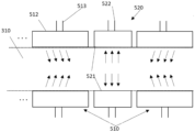
- the climate control system 500 generally comprises an air injection subsystem 510 and an air extraction subsystem 520.
- the air injection subsystem 510 comprises an incoming air entry (not shown), connected with the outside, a plurality of incoming air outputs 512, each incoming air outputs 512 being linked to an incoming air duct 513 which comprises pipes and/or chimneys, and a fan configured to move the air from outside the farming installation 1 to the plurality of incoming air outputs 512.
- two incoming air outputs 512 are provided in the farming installation 1.
- the two incoming air outputs 512 may be placed symmetrically with regard to the longitudinal axis of the containers 310, such as to face each other.
- the two incoming air outputs 512 may be placed either at the entrance longitudinal end 4 of the installation 1 or at any place along a container 310. Such configuration allows to inject air according to a turbulent air flow.
- the turbulent air flow presents several advantages compared to a laminar air flow.
- the turbulent air flow helps to evacuate the metabolic gasses in a more efficient way, while injecting fresh air in the bottom of the substrate.
- the turbulent airflow helps to reach the target temperature by promoting heat exchange between the substrate and the air.
- the turbulent airflow allows to dry the substrate more efficiently at the harvesting step since the drying is more uniformly operated, therefore preventing the formation of a crust at the top surface of the substrate.
- the ploughs 40 of the mobile workstation 10 may also be used in synergy with the climate control system 500 to promote the larvae growth. More precisely, when the sensors of the mobile workstation 10 register that a substrate moisture setpoint is achieved, the ploughs 40 of the mobile workstation 10 may be used iteratively, for example, to plough the substrate according to a certain depth, for example, from 5 cm below the substrate surface down to the whole thickness of 15 cm of the substrate, thereby mixing the dry substrate with the wet substrate to obtain a homogeneous mix on said depth. The time delay between two ploughing may be determined as described above.
- more than two incoming air outputs 512 are provided at each level of the farming installation 1.
- the pair of incoming air outputs 512 are disposed at equidistance from one another according to the longitudinal direction of the farming installation 1 and above the substrate, to inject air in a homogeneous way along the working area, still according to a turbulent airflow.
- the air extraction subsystem 520 comprises at least an air extraction entry 521, the air extraction entry 521 being linked to an extracted air duct 522, such as pipes and/or chimneys, an extracted air output and a fan configured to move the air from the air extraction entry 521 to the extracted air output.
- an extracted air duct 522 such as pipes and/or chimneys
- a fan configured to move the air from the air extraction entry 521 to the extracted air output.
- the air extraction entry 521 is positioned at the side of the opposed output end 13 of the farming installation 1, near the output module 54.
- the injected air can flow from entrance longitudinal end 4or along the container 310 to the opposed output end 13 of each level of the farming installation 1, allowing the ventilation of the whole substrate at each level.
- each extraction entry may be spaced from a same predetermined distance from the others air extraction entries 521 to avoid leakage of air or metabolic gasses and to maximize their efficiency.
- each pair of incoming air outputs 512 may be provided an air extraction entry 521.
- the air extraction entries 521 are placed on the same side of the installation (as illustrated on figure 3 ).
- the air extraction entries 521 may be placed on both sides of the installation (or of a container).
- the air extraction entries 521 are alternatively placed on each side of the installation (or of a container), with regards to the longitudinal length of the installation. For example, a first extraction entry 521 is placed on a first side of the installation, a first pair of air extraction output is placed next to said first extraction entry 521, and a second extraction entry 521 is placed on the second side of the installation. The pattern may then be repeated along the length of the installation. This allows to provide turbulent air flow over the whole length of the containers 310.
- a pair of extraction entries 521 facing each other may be placed.
- the air extracted by the extraction subsystem 520 is the air that has been injected by the air incoming output of the climate control system 500 to the substrate. Sometimes, the extracted air is warmer than the injected air due to the heat exchange taking place between the larvae exhaling heat and the air flowing in the farming installation 1. Such warmer extracted air may furthermore be used to reduce the energy consumption. More precisely, the extracted air duct may be provided next to, or even in direct contact with, the incoming air duct such that the warmer extracted air may be used to heat the incoming air.
- the climate control system 500 may further comprise a heat recovery system that picks up the warmer extracted air and injects it in the incoming air duct. More precisely, all the warmer extracted air or a portion of the warmer extracted air may be injected in the incoming air duct to fulfil a temperature criterion. The portion of the warmer extracted air injected in the incoming air duct may be chosen regarding the temperature of the incoming air. As a non-limitative example, if the air picked up outside in the incoming air duct is at a temperature of 5°C, up to 90% of the warmer extracted air may be injected in the incoming air duct. It may advantageously reduce the overall cost linked to the energy consumption of the installation.
- the warmer extracted air may be first recycled before its injection in the incoming air duct.
- a heat exchanger may further be used to reach the desire temperature.
- the material of the containers 310 is chosen to allow and maximise heat transfer.
- Such material may present a high thermal conductivity (for example superior to 10 W m -1 K -1 ).
- Materials that can be used may comprise inox, aluminium, mild steel, glass fibre, plastic base with a thin metal coating, or a composite material. Inox may be the best material since it is easily washable, reusable, and anticorrosive.
- the choice of the container 310 material allows to reduce the ventilation rate, thereby limiting the energy consumption of the farming installation 1.
Landscapes
- Life Sciences & Earth Sciences (AREA)
- Environmental Sciences (AREA)
- Zoology (AREA)
- Animal Behavior & Ethology (AREA)
- Animal Husbandry (AREA)
- Biodiversity & Conservation Biology (AREA)
- Catching Or Destruction (AREA)
- Health & Medical Sciences (AREA)
- Evolutionary Biology (AREA)
- General Health & Medical Sciences (AREA)
- Marine Sciences & Fisheries (AREA)
- Toxicology (AREA)
- Engineering & Computer Science (AREA)
- Mechanical Engineering (AREA)
Priority Applications (2)
| Application Number | Priority Date | Filing Date | Title |
|---|---|---|---|
| EP23192781.5A EP4512244A1 (de) | 2023-08-22 | 2023-08-22 | Automatisierte anlage zur insektenzucht |
| US18/811,458 US20250064035A1 (en) | 2023-08-22 | 2024-08-21 | Automated insect farming installation |
Applications Claiming Priority (1)
| Application Number | Priority Date | Filing Date | Title |
|---|---|---|---|
| EP23192781.5A EP4512244A1 (de) | 2023-08-22 | 2023-08-22 | Automatisierte anlage zur insektenzucht |
Publications (1)
| Publication Number | Publication Date |
|---|---|
| EP4512244A1 true EP4512244A1 (de) | 2025-02-26 |
Family
ID=87762698
Family Applications (1)
| Application Number | Title | Priority Date | Filing Date |
|---|---|---|---|
| EP23192781.5A Pending EP4512244A1 (de) | 2023-08-22 | 2023-08-22 | Automatisierte anlage zur insektenzucht |
Country Status (2)
| Country | Link |
|---|---|
| US (1) | US20250064035A1 (de) |
| EP (1) | EP4512244A1 (de) |
Citations (7)
| Publication number | Priority date | Publication date | Assignee | Title |
|---|---|---|---|---|
| WO2014171829A1 (en) * | 2013-04-19 | 2014-10-23 | Protix Biosystems B.V. | Method and system for breeding insects, using a plurality of individual crates |
| WO2019022596A1 (en) | 2017-07-25 | 2019-01-31 | Proti-Farm R & D B.V. | METHOD AND SYSTEM FOR CONTROLLING THE CLIMATE OF A CLIMATIC ZONE OF INSECT BREEDING |
| CN110074066A (zh) * | 2019-06-04 | 2019-08-02 | 山东大佳机械有限公司 | 黑水虻立体循环养殖床 |
| EP3747264A1 (de) * | 2019-06-03 | 2020-12-09 | Bühler Insect Technology Solutions AG | Klimasystem |
| WO2020246878A1 (en) * | 2019-06-06 | 2020-12-10 | Protix B.V. | System and method for rearing invertebrates |
| CN113728976A (zh) * | 2021-06-29 | 2021-12-03 | 苏州市格立尔环保技术有限公司 | 黑水虻养殖装置及其上的风箱结构 |
| EP4098114A1 (de) * | 2021-06-03 | 2022-12-07 | Nasekomo B.V. | Automatisierte landwirtschaftliche anlage |
Family Cites Families (5)
| Publication number | Priority date | Publication date | Assignee | Title |
|---|---|---|---|---|
| KR20180047041A (ko) * | 2016-10-31 | 2018-05-10 | (주)헬퍼로보텍 | 산업곤충 사육용 자동화설비 |
| GB201900322D0 (en) * | 2019-01-09 | 2019-02-27 | Ocado Innovation Ltd | Growing systems and methods |
| US12102058B2 (en) * | 2019-04-10 | 2024-10-01 | Beetle Genius, SPRL | Automated insect rearing facility, container, and modules |
| US11311003B2 (en) * | 2020-05-29 | 2022-04-26 | Yu Land Biological Agriculture Co., Ltd. | Mobile culture assembly for feeding larvae of black soldier fly |
| CN115251011B (zh) * | 2021-11-15 | 2023-07-07 | 郑州笨农农业科技有限公司 | 一种腐食性昆虫养殖风干系统及其方法 |
-
2023
- 2023-08-22 EP EP23192781.5A patent/EP4512244A1/de active Pending
-
2024
- 2024-08-21 US US18/811,458 patent/US20250064035A1/en active Pending
Patent Citations (7)
| Publication number | Priority date | Publication date | Assignee | Title |
|---|---|---|---|---|
| WO2014171829A1 (en) * | 2013-04-19 | 2014-10-23 | Protix Biosystems B.V. | Method and system for breeding insects, using a plurality of individual crates |
| WO2019022596A1 (en) | 2017-07-25 | 2019-01-31 | Proti-Farm R & D B.V. | METHOD AND SYSTEM FOR CONTROLLING THE CLIMATE OF A CLIMATIC ZONE OF INSECT BREEDING |
| EP3747264A1 (de) * | 2019-06-03 | 2020-12-09 | Bühler Insect Technology Solutions AG | Klimasystem |
| CN110074066A (zh) * | 2019-06-04 | 2019-08-02 | 山东大佳机械有限公司 | 黑水虻立体循环养殖床 |
| WO2020246878A1 (en) * | 2019-06-06 | 2020-12-10 | Protix B.V. | System and method for rearing invertebrates |
| EP4098114A1 (de) * | 2021-06-03 | 2022-12-07 | Nasekomo B.V. | Automatisierte landwirtschaftliche anlage |
| CN113728976A (zh) * | 2021-06-29 | 2021-12-03 | 苏州市格立尔环保技术有限公司 | 黑水虻养殖装置及其上的风箱结构 |
Also Published As
| Publication number | Publication date |
|---|---|
| US20250064035A1 (en) | 2025-02-27 |
Similar Documents
| Publication | Publication Date | Title |
|---|---|---|
| EP3277081B1 (de) | Mehrphasige modularisierte garnelenproduktionssystem und -verfahren | |
| US20150196002A1 (en) | Automated hybrid aquaponics and bioreactor system including product processing and storage facilities with integrated robotics, control system, and renewable energy system cross-reference to related applications | |
| CN111528104A (zh) | 禽畜养殖装备、恒温供气系统以及禽畜恒温养殖方法 | |
| CN106376448A (zh) | 高生长率的浮游水生物种的培育、收获及加工 | |
| US8863435B2 (en) | Architecture for symbiotic livestock and biofuel production | |
| CN112806284A (zh) | 一种层叠式家禽养殖设备及其系统 | |
| EP4512244A1 (de) | Automatisierte anlage zur insektenzucht | |
| CN220545686U (zh) | 蚯蚓养殖与蔬菜种植用不等跨日光温室 | |
| CN211960613U (zh) | 一种黑水虻幼虫养殖装置 | |
| CA2891676C (en) | System and method for producing biogas | |
| CN101627731A (zh) | 一种无公害养鸡方法及定时行走翻料专用设备 | |
| CN111202031A (zh) | 一种黑水虻幼虫养殖装置、方法 | |
| CN215012784U (zh) | 用于黑水虻养殖的自动布料饲养系统 | |
| CN211298086U (zh) | 一种家禽养殖用粪便清理装置 | |
| CN108575914A (zh) | 一种昆虫转化农业有机废弃物的装置及其使用方法 | |
| CN211607921U (zh) | 可生物处理湿垃圾的自动化养殖黑水虻系统 | |
| CN108419761A (zh) | 蛆粪自动分离养殖的方法 | |
| CN108902468A (zh) | 蛆蛋白生物有机饲料及其制备方法 | |
| WO2019041648A1 (zh) | 一种用于生态养殖的阳光房 | |
| WO2011049434A2 (en) | System for producing agricultural products like food and/or for processing of waste streams. | |
| EP4470372A1 (de) | Mobile arbeitsstation zur erdlosen kultivierung in der automatisierten insektenzucht | |
| EP3462846B1 (de) | Viehunterbringungsanlage | |
| RU2292711C2 (ru) | Устройство для выращивания личинок синантропных мух | |
| CN107006379A (zh) | 一种环保生态的养猪方法 | |
| CN208300674U (zh) | 一种用于肉鸭规模化养殖的层叠式养殖设备 |
Legal Events
| Date | Code | Title | Description |
|---|---|---|---|
| PUAI | Public reference made under article 153(3) epc to a published international application that has entered the european phase |
Free format text: ORIGINAL CODE: 0009012 |
|
| STAA | Information on the status of an ep patent application or granted ep patent |
Free format text: STATUS: THE APPLICATION HAS BEEN PUBLISHED |
|
| AK | Designated contracting states |
Kind code of ref document: A1 Designated state(s): AL AT BE BG CH CY CZ DE DK EE ES FI FR GB GR HR HU IE IS IT LI LT LU LV MC ME MK MT NL NO PL PT RO RS SE SI SK SM TR |
|
| STAA | Information on the status of an ep patent application or granted ep patent |
Free format text: STATUS: REQUEST FOR EXAMINATION WAS MADE |
|
| STAA | Information on the status of an ep patent application or granted ep patent |
Free format text: STATUS: EXAMINATION IS IN PROGRESS |
|
| 17P | Request for examination filed |
Effective date: 20250718 |
|
| 17Q | First examination report despatched |
Effective date: 20250813 |
|
| REG | Reference to a national code |
Ref country code: DE Ref legal event code: R079 Free format text: PREVIOUS MAIN CLASS: A01K0067033000 Ipc: A01K0067360000 |
|
| RIC1 | Information provided on ipc code assigned before grant |
Ipc: A01K 67/36 20250101AFI20251208BHEP Ipc: A01K 67/364 20250101ALI20251208BHEP |
|
| GRAP | Despatch of communication of intention to grant a patent |
Free format text: ORIGINAL CODE: EPIDOSNIGR1 |
|
| STAA | Information on the status of an ep patent application or granted ep patent |
Free format text: STATUS: GRANT OF PATENT IS INTENDED |
|
| INTG | Intention to grant announced |
Effective date: 20260115 |