EP4357786B1 - Vertikalübertragungseinrichtung - Google Patents
Vertikalübertragungseinrichtung Download PDFInfo
- Publication number
- EP4357786B1 EP4357786B1 EP23165098.7A EP23165098A EP4357786B1 EP 4357786 B1 EP4357786 B1 EP 4357786B1 EP 23165098 A EP23165098 A EP 23165098A EP 4357786 B1 EP4357786 B1 EP 4357786B1
- Authority
- EP
- European Patent Office
- Prior art keywords
- carrier
- positioning
- base
- transmission equipment
- roller member
- Prior art date
- Legal status (The legal status is an assumption and is not a legal conclusion. Google has not performed a legal analysis and makes no representation as to the accuracy of the status listed.)
- Active
Links
Images





Classifications
-
- G—PHYSICS
- G01—MEASURING; TESTING
- G01N—INVESTIGATING OR ANALYSING MATERIALS BY DETERMINING THEIR CHEMICAL OR PHYSICAL PROPERTIES
- G01N35/00—Automatic analysis not limited to methods or materials provided for in any single one of groups G01N1/00 - G01N33/00; Handling materials therefor
- G01N35/02—Automatic analysis not limited to methods or materials provided for in any single one of groups G01N1/00 - G01N33/00; Handling materials therefor using a plurality of sample containers moved by a conveyor system past one or more treatment or analysis stations
- G01N35/04—Details of the conveyor system
-
- B—PERFORMING OPERATIONS; TRANSPORTING
- B65—CONVEYING; PACKING; STORING; HANDLING THIN OR FILAMENTARY MATERIAL
- B65G—TRANSPORT OR STORAGE DEVICES, e.g. CONVEYORS FOR LOADING OR TIPPING, SHOP CONVEYOR SYSTEMS OR PNEUMATIC TUBE CONVEYORS
- B65G17/00—Conveyors having an endless traction element, e.g. a chain, transmitting movement to a continuous or substantially-continuous load-carrying surface or to a series of individual load-carriers; Endless-chain conveyors in which the chains form the load-carrying surface
- B65G17/16—Conveyors having an endless traction element, e.g. a chain, transmitting movement to a continuous or substantially-continuous load-carrying surface or to a series of individual load-carriers; Endless-chain conveyors in which the chains form the load-carrying surface comprising individual load-carriers which are pivotally mounted, e.g. for free-swinging movement
- B65G17/18—Conveyors having an endless traction element, e.g. a chain, transmitting movement to a continuous or substantially-continuous load-carrying surface or to a series of individual load-carriers; Endless-chain conveyors in which the chains form the load-carrying surface comprising individual load-carriers which are pivotally mounted, e.g. for free-swinging movement and move in contact with a guiding surface
-
- G—PHYSICS
- G01—MEASURING; TESTING
- G01N—INVESTIGATING OR ANALYSING MATERIALS BY DETERMINING THEIR CHEMICAL OR PHYSICAL PROPERTIES
- G01N35/00—Automatic analysis not limited to methods or materials provided for in any single one of groups G01N1/00 - G01N33/00; Handling materials therefor
- G01N35/0099—Automatic analysis not limited to methods or materials provided for in any single one of groups G01N1/00 - G01N33/00; Handling materials therefor comprising robots or similar manipulators
-
- G—PHYSICS
- G01—MEASURING; TESTING
- G01N—INVESTIGATING OR ANALYSING MATERIALS BY DETERMINING THEIR CHEMICAL OR PHYSICAL PROPERTIES
- G01N35/00—Automatic analysis not limited to methods or materials provided for in any single one of groups G01N1/00 - G01N33/00; Handling materials therefor
- G01N2035/00465—Separating and mixing arrangements
- G01N2035/00534—Mixing by a special element, e.g. stirrer
-
- G—PHYSICS
- G01—MEASURING; TESTING
- G01N—INVESTIGATING OR ANALYSING MATERIALS BY DETERMINING THEIR CHEMICAL OR PHYSICAL PROPERTIES
- G01N35/00—Automatic analysis not limited to methods or materials provided for in any single one of groups G01N1/00 - G01N33/00; Handling materials therefor
- G01N35/02—Automatic analysis not limited to methods or materials provided for in any single one of groups G01N1/00 - G01N33/00; Handling materials therefor using a plurality of sample containers moved by a conveyor system past one or more treatment or analysis stations
- G01N35/04—Details of the conveyor system
- G01N2035/0401—Sample carriers, cuvettes or reaction vessels
- G01N2035/0418—Plate elements with several rows of samples
-
- G—PHYSICS
- G01—MEASURING; TESTING
- G01N—INVESTIGATING OR ANALYSING MATERIALS BY DETERMINING THEIR CHEMICAL OR PHYSICAL PROPERTIES
- G01N35/00—Automatic analysis not limited to methods or materials provided for in any single one of groups G01N1/00 - G01N33/00; Handling materials therefor
- G01N35/02—Automatic analysis not limited to methods or materials provided for in any single one of groups G01N1/00 - G01N33/00; Handling materials therefor using a plurality of sample containers moved by a conveyor system past one or more treatment or analysis stations
- G01N35/04—Details of the conveyor system
- G01N2035/0401—Sample carriers, cuvettes or reaction vessels
- G01N2035/0418—Plate elements with several rows of samples
- G01N2035/0425—Stacks, magazines or elevators for plates
Definitions
- the disclosure relates to a transfer equipment, more particularly relates to a vertical transmission equipment.
- US2011/0200419A1 discloses a shuttle-type conveying system to convey an article.
- US2008/0213080A1 discloses a compact storage system and a corresponding method for storing frozen specimens.
- US 5,738,225A discloses a device in which a bookrack moves vertically and horizontally.
- DE101 41 074A1 discloses a paternostic goods storage system, comprises goods supports which can be moved up and down along and horizontally between vertical conveyors.
- WO2009/145742A2 discloses a stand/rack system with movement mechanism.
- WO2007/071988A1 discloses a storage system.
- WO2018/210088A1 discloses a warehouse-out and warehouse-in device.
- one aspect of the disclosure is to provide a vertical transmission equipment capable of solving the problem due to conventional equipment.
- the invention is set out in the appended set of claims.
- One embodiment of the disclosure provides a vertical transmission equipment including a base having a mount surface, a rail structure disposed on the mount surface, and a carrier movably disposed on the rail structure, the carrier comprises a supporting surface, and the supporting surface of the carrier is perpendicular to the mount surface of the base.
- One embodiment of the disclosure provides a vertical transmission equipment including a base, a rail structure disposed on the base, and a carrier movably disposed on the rail structure, the carrier has a supporting surface, and the supporting surface of the carrier and the rail structure do not overlap with each other in a normal line of the supporting surface.
- One embodiment of the disclosure provides a vertical transmission equipment including a base and a carrier comprising a supporting surface and movably disposed on the base along a transmission path, the supporting surface of the carrier is perpendicular to an imaginary plane which is defined by the transmission path of the carrier.
- the supporting surface of the carrier is perpendicular to the mount surface of the base, the supporting surface does not overlap with the rail structure in the normal line of the supporting surface, or the supporting surface of the carrier is perpendicular to the imaginary plane which is defined by the transmission path of the carrier, thus the supporting surface of the carrier is kept in an angle perpendicular to the base and the rail structure.
- the vertical transmission equipment achieves a well plate carrier capable of movable in vertical manner, which makes the vertical transmission equipment take lesser horizontal space and therefore is favorable for increasing the number of equipments in a laboratory constrained by limited space.
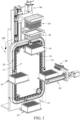
- the vertical transmission equipment 1 may include a base 10, a rail structure 20 and a carrier 30.
- the rail structure 20 is disposed on the base 10.
- the base 10 may have a mount surface 11, the mount surface 11 means the surface of the base 10 in which the rail structure 20 is located.
- the carrier 30 is movably disposed on the rail structure 20 and therefore the carrier 30 is movable along a transmission path MP on the rail structure 20 relative to the base 10.
- the rail structure 20 defines the transmission path MP for the carrier 30 to move relatively to the base 10.
- the rail structure 20 may be a closed loop rail in a required shape, thus, as shown, the transmission path MP of the carrier 30 may be a closed loop on an imaginary plane P1. Note that imaginary plane P1 is defined by the transmission path MP. As such, the carrier 30 is able to be repeatedly moved to different areas of the base 10 along the transmission path MP.
- the carrier 30 may include a supporting surface 321, the supporting surface 321 may be a flat surface of the carrier 30 configured for supporting a well plate 81; in other words, the supporting surface 321 means a surface of the carrier 30 that is used to support the well plate 81.
- An imaginary plane P2 in which the supporting surface 321 is located is perpendicular to the imaginary plane P1 which is defined by the transmission path MP. Note that the imaginary plane P2 is defined by the supporting surface 321.
- the supporting surface 321 of the carrier 30 may be perpendicular to the mount surface 11 of the base 10 and the rail structure 20.
- the supporting surface 321 of the carrier 30 does not overlap with the rail structure 20 and the mount surface 11 of the base 10 , such that the supporting surface 321 of the carrier 30 is kept at an angle perpendicular to the base 10 and the rail structure 20 when moving.
- the vertical transmission equipment 1 takes up lesser horizontal or lateral space and therefore is favorable for increasing the number of vertical transmission equipments in a limited space.
- the well plate 81 may be any suitable multiwell plate with multiple sample wells used as small test tubes.
- the well plate 81 may have 96, lesser, or more sample wells arranged in a matrix.
- the well plate 81 may be movable relative to the base 10 along the transmission path MP by being carried by the carrier 30. Note that the number of the carrier 30 that the base 10 can support may be modified as required and not intended to limit the disclosure. It is also noted that the well plate that the carrier 30 can support is merely provided for better understanding the disclosure but is not intended to limit the disclosure.
- the vertical transmission equipment 1 may further include a roller member 40.
- the roller member 40 is movably disposed on the rail structure 20 and therefore is only allowed to be movable along the transmission path MP relative to the base 10.
- the carrier 30 is pivotally connected to the roller member 40 about an axis AX.
- the carrier 30 is movable along the transmission path MP and is rotatable about the axis AX relative to the base 10 and the rail structure 20.
- the gravitational force can naturally correct the carrier 30 to a position that makes the normal line NL of its supporting surface 321 parallel to the direction of gravity G; in other words, when the rail structure 20 is placed in vertical manner, the supporting surface 321 of the carrier 30 may be self-positioned to be horizontal manner by gravitational force, thereby automatically correcting the angle of the well plate 81 to be horizontal during the movement of the carrier 30 relative to the base 10.
- the vertical transmission equipment 1 may be cooperated with a sleeve set 82, a magnetic rod set 83, and a lifting mechanism 84.
- the lifting mechanism 84 may be disposed on the base 10.
- the sleeve set 82 and magnetic rod set 83 may be connected to different rails of the lifting mechanism 84 and therefore can be moved in vertical direction separately.
- the lifting mechanism 84 may move the sleeve set 82 and magnetic rod set 83 into the wells of the well plate 81 in the required order, the lifting mechanism 84 then can cause the sleeve set 82 and magnetic rod set 83 to vibrate in a predetermined manner so as to perform the required process to the substance stored in the wells.
- the vertical transmission equipment 1 may be cooperated with a feeding mechanism 85 and a substance feeder 86.
- the feeding mechanism 85 may be disposed on the base 10 or disposed on an external structure so as to be located adjacent to the base 10.
- the substance feeder 86 is connected to and movable by the feeding mechanism 85.
- the substance feeder 86 may be moved horizontally by being driven by the feeding mechanism 85.
- the feeding mechanism 85 can move the substance feeder 86 to above the well plate 81 so that the substance feeder 86 can add required substance into the selected wells.
- the vertical transmission equipment 1 may use the carrier 30 to move the well plate 81 to another selected area of the base 10 for performing another process, but the disclosure is not limited thereto.
- the vertical transmission equipment 1 may further include a power source 87, a plurality of transmission gears 12, and a transmission component 50.
- the transmission gears 12 are pivotally disposed on the mount surface 11 of the base 10 and are arranged adjacent to the rail structure 20.
- the power source 87 may be any suitable motor.
- the power source 87 may be disposed on the base 10 and connected to one of the transmission gears 12, thus the power source 87 is able to rotate the transmission gear 12 relative to the base 10.
- the transmission component 50 may be any suitable gear chain capable of meshing with the transmission gears 12.
- the transmission component 50 may be arranged along the rail structure 20 (or, along the transmission path MP ) and is movably disposed on the base 10 via the transmission gears 12. As such, the transmission gear 12 that is connected to the power source 87 can simultaneously cause the other transmission gears 12 to rotate via the transmission component 50 when being driven by the power source 87.
- FIG. 4 is a partially-enlarged view of the vertical transmission equipment 1
- FIG. 5 is a partially enlarged view of the transmission component 50
- FIGS. 6-7 are partially-enlarged cross-sectional views of the vertical transmission equipment 1 taken from different view angles.
- the vertical transmission equipment 1 may further include a shaft 71.
- the shaft 71 is disposed through the roller member 40.
- the transmission component 50 may include a plurality of outer plates.
- the shaft 71 may be inserted into one of the outer plates of the transmission component 50 (e.g., an outer plate 51 ).
- the outer plate 51 may include a plate portion 511.
- the plate portion 511 may include a shaft hole 5112 and a mount portion 5111.
- the shaft 71 is disposed through the shaft hole 5112.
- the outer plate 51 is fixed to other parts of the transmission component 50 (not numbered, such as inner plate and rollers) via its mount portion 5111.
- the carrier 30 may include a bridging structure 31 and a supporting structure 32.
- the supporting structure 32 means the part of the carrier 30 used to support the well plate 81.
- the supporting structure 32 may include the supporting surface 321.
- the bridging structure 31 may be pivotally disposed on the shaft 71 and connects the supporting structure 32, thus, the supporting structure 32 is connected to the shaft 71 via the bridging structure 31 and the bridging structure 31 is pivotally connected to the roller member 40 via the shaft 71.
- the bridging structure 31 may include a connecting portion 311 and a distal portion 312 which are located opposite to each other.
- the connecting portion 311 means the portion of the bridging structure 31 in which the supporting structure 32 is connected to the bridging structure 31, and the distal portion 312 means the portion of the bridging structure 31 that is pivotally sleeved on the shaft 71.
- At least part of the outer plate 51 of the transmission component 50 may be pivotally connected to and located between the bridging structure 31 of the carrier 30 and the roller member 40, thus, the carrier 30 and the roller member 40 are both rotatable relative to the outer plate 51.
- the power source 87 causes the transmission component 50 to move by driving the transmission gear 12 connected thereto, the power source 87 is able to move the shaft 71 which penetrates through the carrier 30 and the roller member 40 via the outer plate 51 of the transmission component 50 thereby causing the shaft 71, the carrier 30 and the roller member 40 to move along the transmission path MP.
- the vertical transmission equipment 1 may selectively position the carrier 30 in the selected area of the base 10 that is favorable for keeping the carrier 30 in horizontal position. For example, the vertical transmission equipment 1 may selectively move the carrier 30 to a specific position that the supporting surface 321 of the carrier 30 and the well plate 81 on the carrier 30 can kept in horizontal due to gravitational force.
- the vertical transmission equipment 1 may further include a positioning assembly 60 and a first sensor S1, and the transmission component 50 may further include a protrusion structure 512 protruding from the plate portion 511.
- the positioning assembly 60 may be disposed on the base 10.
- the positioning assembly 60 may include a power source 88 and a positioning structure 61.
- the power source 88 may be any suitable motor.
- the power source 88 may be disposed on the base 10.
- the positioning structure 61 may be connected to the power source 88 and is movably disposed on the base 10 via the power source 88. Specifically, the power source 88 is able to move the positioning structure 61 back and forth along a direction parallel to the axis AX.
- the bridging structure 31 of the carrier 30 may further include a positioning hole 313.
- the positioning hole 313 may be located between the connecting portion 311 and the distal portion 312 of the bridging structure 31.
- the positioning hole 313 and the axis AX may be respectively located adjacent to two opposite ends of the bridging structure 31.
- the first sensor S1 may be disposed on the base 10.
- the first sensor S1 may be disposed on or adjacent to the path that the protrusion structure 512 travels.
- the carrier 30 is determined to be in the predetermined position.
- the power source 88 is able to move the positioning structure 61 of the positioning assembly 60 into the positioning hole 313 of the carrier 30 so as to prevent the carrier 30 from rotating relative to the base 10.
- the positioning assembly 60 may further include a second sensor S2.
- the second sensor S2 may be disposed on the base 10.
- the second sensor S2 may be disposed on or adjacent to the path that the positioning structure 61 of the positioning assembly 60 travels.
- the second sensor S2 senses the positioning structure 61, it is determined that the power source 88 already causes the positioning structure 61 to move out of the positioning hole 313 of the carrier 30 and thereby preventing the positioning structure 61 from interfering the later movement of the carrier 30.
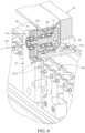
- FIG. 8 depicts that the carrier 30 is positioned by the positioning assembly 60.
- the transmission component 50 can move the carrier 30 and the roller member 40 along the transmission path MP to the position in FIG. 8 by its outer plate 51 and shaft 71.
- the first sensor S1 senses the protrusion structure 512 of the outer plate 51 (in other words, when the protrusion structure 512 moves to the area can be sensed by the first sensor S1 ), meaning that the carrier 30 reaches the predetermined position.
- the power source 87 stops driving the transmission component 50, and the power source 88 moves the positioning structure 61 of the positioning assembly 60 into the positioning hole 313 on the bridging structure 31 of the carrier 30. That is, when the positioning structure 61 is inserted into the positioning hole 313, the carrier 30 is positioned. As such, the positioning assembly 60 can secure the part of the bridging structure 31 which is located away from the axis AX using the positioning structure 61 so as to secure the angle and position of the carrier 30. In other words, the positioning structure 61 of the positioning assembly 60 is selectively inserted into the positioning hole 313 which is located away from the axis AX. At that moment, the normal line NL of the imaginary plane P2 in which the supporting surface 321 of the carrier 30 is located is parallel to the direction of gravity G. As a result, the positioning assembly 60 secures the supporting surface 321 of the carrier 30 in horizontal status.
- the power source 88 withdraws the positioning structure 61 of the positioning assembly 60 from the positioning hole 313 of the carrier 30.
- the second sensor S2 senses the positioning structure 61, it is determined that the positioning structure 61 is moved to a position that does not interfere the movement of the carrier 30.
- the power source 87 then can drive the transmission component 50 again to move the carrier 30 and the roller member 40 along the transmission path MP.
- the previous vertical transmission equipment is one of exemplary embodiments of the disclosure but is not intended to limit the disclosure. It is also noted that the vertical transmission equipment can be modified as required.
- the following provides vertical transmission equipments of other embodiments which are capable of achieving the effect the same as shown in, for example, FIG. 8 , but for the purpose of simplicity, only the main differences between the introduced embodiment and the previous embodiments will be described in detail, and the same or similar parts can be comprehended with reference to the corresponding paragraphs and thus will not be repeatedly described hereinafter. It is also noted that the same reference number denote the same component or element.
- the positioning assembly 60' may include a positioning structure 61', a spanning portion 62, a fixed portion 63, a pushable component 64, at least one guiding rod 65, and at least one elastic component 66.
- the rail structure 20' may include a through hole 21.
- the fixed portion 63 may be fixed to the base 10.
- the guiding rod 65 is disposed through the fixed portion 63.
- the pushable component 64 and one end of the spanning portion 62 are respectively connected to two opposite ends of the guiding rod 65.
- the pushable component 64 may be movably located at a through hole 21 of the rail structure 20'.
- the first sensor S1 may be disposed on the fixed portion 63. Specifically, the first sensor S1 may be located at a side (or, surface) of the fixed portion 63 which faces toward the pushable component 64.
- the elastic component 66 may be any suitable compression spring.
- the elastic component 66 may be sleeved on the guiding rod 65 and sandwiched between the pushable component 64 and the fixed portion 63 (or, two opposite ends of the elastic component 66 are respectively in contact with the pushable component 64 and the fixed portion 63 ), such that the elastic component 66 is able to force the pushable component 64 to move away from the fixed portion 63 and thereby causing at least part of the pushable component 64 to penetrate through the through hole 21 and into the rail structure 20'.
- the pushable component 64 may include an abutting inclined surface 641 and a releasing inclined surface 642 which are respectively located at two opposite sides thereof and are both inclined relative to the transmission path MP.
- the abutting inclined surface 641 and the releasing inclined surface 642 may be kept in the rail structure 20 and therefore are kept in the path that the roller member 40 travels.
- the abutting inclined surface 641 means the slope or slanted surface of the pushable component 64 that is configured for receiving the push from the roller member 40.
- the releasing inclined surface 642 means another slope or slanted surface of the pushable component 64 that is inclined relative to the abutting inclined surface 641.
- the positioning structure 61' is connected to one end of the spanning portion 62, and the guiding rod 65 stands at the opposing end of the spanning portion 62.
- the positioning structure 61' may have a shape extending downward from a distal end of the spanning portion 62.
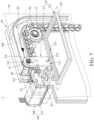
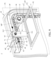
- FIGS. 9-10 show that the carrier 30' moves along the transmission path MP to a position of just contacting the abutting inclined surface 641 of the positioning assembly 60' which is kept in the rail structure 20' by the elastic component 66.
- the motion of the roller member 40 in the transmission path MP can apply force to push the abutting inclined surface 641 so as to force the pushable component 64 to move out of the rail structure 20'.
- the pushable component 64 is selectively removed out of the through hole 21 of the rail structure 20' by being pushed by the roller member 40.
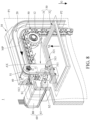
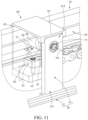
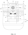
- the pushable component 64 moves the positioning structure 61' in the same direction through the guiding rod 65 and the spanning portion 62. Then, as shown in FIG. 11-12 , a distal portion 312' of the bridging structure 31' of the carrier 30' and the positioning structure 61' are moved to engage with each other. As a result, the carrier 30' is captured by the positioning assembly 60' so that the angle and position of the carrier 30' are secured. Meanwhile, the movement of the pushable component 64 driven by the roller member 40 can activate the first sensor S1 so that the transmission component 50' is stopped moving the carrier 30' accordingly. It is noted that the first sensor S1 may correspond to the pushable component 64 and therefore the outer plate 51' of the transmission component 50' in this embodiment may omit the aforementioned protrusion structure 512.
- the transmission component 50 may be activated again to move the carrier 30' and the roller member 40 along the transmission path MP, such that the roller member 40 can move onto the releasing inclined surface 642 of the pushable component 64.
- the pushable component 64 gradually enters into the rail structure 20' by being forced by the elastic component 66, and the positioning structure 61' may be simultaneously moved in the same direction via the guiding rod 65 and the spanning portion 62, such that the positioning structure 61' releases the bridging structure 31' of the carrier 30', thereby allowing the roller member 40 and the carrier 30' to keep moving along the transmission path MP.
- the positioning assembly 60 " may include a first positioning structure 61a, a second positioning structure 61b, a first driving gear 671, a first driven gear 672, a second driving gear 673, and a second driven gear 674, where the first driving gear 671, the first driven gear 672, the second driving gear 673, and the second driven gear 674 may be any suitable helical gear whose teeth are cut at an angle to the axis.
- the first driving gear 671 may be connected to the power source 88 and is movably disposed on the base 10 via the power source 88. Specifically, the power source 88 is able to rotate the first driving gear 671 about a direction perpendicular to the axis AX, the first driven gear 672 is meshed with the first driving gear 671, the first positioning structure 61a is fixed to the first driven gear 672 and therefore is movably connected to the first driving gear 671 via the first driven gear 672.
- the second driving gear 673 may be connected to the power source 88 and is movably disposed on the base 10 via the power source 88.
- the second driving gear 673 and the first driving gear 671 may be coaxially disposed on the shaft of the power source 88, thus the power source 88 is able to rotate the second driving gear 673 about the direction perpendicular to the axis AX.
- the first driving gear 671 and the second driving gear 673 may have opposite helices.
- the first driving gear 671 and the second driving gear 673 may be two independent gears, but the disclosure is not limited thereto; for example, in other embodiments, the first driving gear 671 and the second driving gear 673 may be integrally formed with each other.
- the second driven gear 674 is meshed with the second driving gear 673, the second positioning structure 61b is fixed to the second driven gear 674 and therefore is movably connected to the second driving gear 673 via the second driven gear 674.
- the first driving gear 671 and the second driving gear 673 are able to rotate the first positioning structure 61a and the second positioning structure 61b in opposite directions by rotating the first driven gear 672 and the second driven gear 674.
- the power source 88 can accordingly cause the first positioning structure 61a and the second positioning structure 61b to rotate in opposite directions (as indicated by the arrows) via the first driving gear 671 and the first driven gear 672 and the second driving gear 673 and the second driven gear 674, such that the first positioning structure 61a and the second positioning structure 61b will contact or appear at two opposite sides of the bridging structure 31 of the carrier 30.
- the part of the carrier 31 which is located relatively away from the axis AX can be clamped or held by the first positioning structure 61a and the second positioning structure 61b (or, sandwiched between the first positioning structure 61 a and the second positioning structure 61b ), so that the angle and position of the carrier 30 are secured.
- the power source 88 may reversely rotate the first driving gear 671 and the second driving gear 673 to move the first positioning structure 61 a and the second positioning structure 61b away from the carrier 30.
- the second sensor S2 senses one of the positioning structures (e.g., the first positioning structure 61a )
- the vertical transmission equipments in some other embodiments may omit the aforementioned second positioning structure, second driving gear, and second driven gear and only remain the first driving gear, the first driven gear, and the first positioning structure to stop at one side of the carrier.
- the supporting surface of the carrier is perpendicular to the mount surface of the base, the supporting surface does not overlap with the rail structure in the normal line of the supporting surface, or the supporting surface of the carrier is perpendicular to the imaginary plane which is defined by the transmission path of the carrier, thus, the supporting surface of the carrier is movably kept in an angle perpendicular to the base and the rail structure.
- the vertical transmission equipment achieves a well plate carrier capable of movable in vertical manner, which makes the vertical transmission equipment take lesser horizontal space and therefore is favorable for increasing the number of equipments in a laboratory constrained by limited space.
Landscapes
- Chemical & Material Sciences (AREA)
- General Physics & Mathematics (AREA)
- Pathology (AREA)
- Physics & Mathematics (AREA)
- Health & Medical Sciences (AREA)
- Life Sciences & Earth Sciences (AREA)
- Immunology (AREA)
- Biochemistry (AREA)
- Engineering & Computer Science (AREA)
- General Health & Medical Sciences (AREA)
- Analytical Chemistry (AREA)
- Mechanical Engineering (AREA)
- Robotics (AREA)
- Transmission Devices (AREA)
- Chain Conveyers (AREA)
Claims (12)
- Vertikalübertragungseinrichtung (1) mit:einer Basis (10); undeinem Träger (30) mit einer Stützfläche (321) und einer Well-Platte (81), welche von der Stützfläche gestützt ist und entlang eines Übertragungswegs (MP) bewegbar auf der Basis angeordnet ist;wobei die Stützfläche des Trägers zu einer imaginären Ebene (PI) senkrecht verläuft, welche durch den Übertragungsweg des Trägers definiert ist,wobei die Vertikalübertragungseinrichtung ferner ein bewegbar an der Basis angeordnetes Rollenelement (40) aufweist, der Träger eine Brückenstruktur (31) und eine Stützstruktur (32) aufweist, die Brückenstruktur schwenkbar mit dem Rollenelement verbunden ist und mit der Stützstruktur verbunden ist, und die Stützfläche auf der Stützstruktur angeordnet ist,dadurch gekennzeichnet,dass die Vertikalübertragungseinrichtung ferner eine auf der Basis angeordnete Positionierungsanordnung (60) aufweist, die Positionierungsanordnung eine Positionierungsstruktur (61) aufweist, die Brückenstruktur des Trägers ein Positionierungsloch (313) aufweist, die Positionierungsstrukturen der Positionierungsanordnung selektiv in das Positionierungsloch eingeführt wird, und wenn die Positionierungsanordnung in das Positionierungsloch eingeführt ist, der Träger positioniert ist.
- Vertikalübertragungseinrichtung nach Anspruch 1, bei welcher die Brückenstruktur des Trägers um eine Achse (AX) schwenkbar mit dem Rollenelement verbunden ist, und das Positionierungsloch und die Achse jeweils zwei entgegengesetzten Enden der Brückenstruktur benachbart angeordnet sind.
- Vertikalübertragungseinrichtung nach Anspruch 1, ferner mit einem ersten Sensor (S1) und einer Übertragungskomponente (50), wobei der erste Sensor an der Basis angeordnet ist, die Übertragungskomponente bewegbar an der Basis angeordnet ist, die Übertragungskomponente einen Plattenbereich (511) und eine Vorsprungsstruktur (512) aufweist, welche von dem Plattenbereich absteht, ein Teil des Plattenbereichs schwenkbar zwischen dem Rollenelement und der Brückenstruktur des Trägers verbunden ist, und wenn die Vorsprungsstruktur durch den ersten Sensor erfasst wird, die Positionierungsstruktur in das Positionierungsloch eingeführt wird und der Träger positioniert wird.
- Vertikalübertragungseinrichtung nach Anspruch 1, bei welcher die Positionierungsanordnung ferner einen zweiten Sensor (S2) aufweist, der an der Basis angeordnet ist, wobei der zweite Sensor dazu ausgebildet ist, durch Erfassen der Positionierungsstruktur festzustellen, ob die Positionierungsstruktur aus dem Positionierungsloch bewegt wird.
- Vertikalübertragungseinrichtung (1') mit:einer Basis (10); undeinem Träger (30') mit einer Stützfläche (321) und einer Well-Platte (81), welche von der Stützfläche gestützt ist und entlang eines Übertragungswegs (MP) bewegbar auf der Basis angeordnet ist;wobei die Stützfläche des Trägers zu einer imaginären Ebene (PI) senkrecht verläuft, welche durch den Übertragungsweg des Trägers definiert ist,wobei die Vertikalübertragungseinrichtung ferner ein bewegbar an der Basis angeordnetes Rollenelement (40) aufweist, der Träger eine Brückenstruktur (31) und eine Stützstruktur (32) aufweist, die Brückenstruktur schwenkbar mit dem Rollenelement verbunden ist und mit der Stützstruktur verbunden ist, und die Stützfläche auf der Stützstruktur angeordnet ist,dadurch gekennzeichnet,dass die Vertikalübertragungseinrichtung ferner aufweist: eine auf der Basis angeordnete Positionierungsanordnung (60'), eine drückbare Komponente (64), eine Spannfläche (62), einen festen Bereich (63), eine Führungsstange (65) und eine elastische Komponente (66), wobei der feste Bereich an der Basis angeordnet ist, die Führungsstange durch den festen Bereich hindurch angeordnet ist, die drückbare Komponente und der Spannbereich jeweils mit zwei entgegengesetzten Enden der Führungsstange verbunden sind, die Basis ein Durchgangsloch (21) aufweist, die drückbare Komponente bewegbar an dem Durchgangsloch angeordnet ist und teilweise in der Basis angeordnet ist, die elastische Komponente auf die Führungsstange gesetzt ist und sandwichartige zwischen der drückbaren Komponente und dem festen Bereich angeordnet ist, die Positionierungsstruktur mit dem Spannbereich verbunden ist, und die drückbare Komponente durch das Rollenelement selektiv aus dem Durchgangsloch bewegt wird, um das Zusammengreifen der Positionierungsstruktur mit der Brückenstruktur des Trägers zu bewirken.
- Vertikalübertragungseinrichtung nach Anspruch 5, ferner mit einem ersten Sensor (S1), der an einer der drückbaren Komponente zugewandten Seite des festen Bereichs der Positionierungsanordnung angeordnet ist, wobei der erste Sensor aktiviert wird, wenn die drückbare Komponente durch das Rollenelement gedrückt wird.
- Vertikalübertragungseinrichtung nach Anspruch 5, bei welcher die drückbare Komponente schräge Anlagefläche (641) und eine schräge Freigabefläche (642) aufweist, die einander entgegengesetzt angeordnet sind, und die schräge Freigabefläche und die schräge Anlagefläche selektiv in der Basis angeordnet sind und selektiv von dem Rollenelement berührt werden.
- Vertikalübertragungseinrichtung (1") mit:einer Basis (10); undeinem Träger (30') mit einer Stützfläche (321) und einer Well-Platte (81), welche von der Stützfläche gestützt ist und entlang eines Übertragungswegs (MP) bewegbar auf der Basis angeordnet ist;wobei die Stützfläche des Trägers zu einer imaginären Ebene (PI) senkrecht verläuft, welche durch den Übertragungsweg des Trägers definiert ist,dadurch gekennzeichnet,dass die Vertikalübertragungseinrichtung ferner eine Positionierungsanordnung (60") aufweist, wobei die Positionierungsanordnung ein erstes Antriebszahnrad (671), ein erstes angetriebenes Zahnrad (672) und eine erste Positionierungsstruktur (61a) aufweist, das erste Antriebszahnrad schwenkbar an der Basis angeordnet ist, und die erste Positionierungsstruktur über das erste angetriebene Zahnrad durch das erste Antriebszahnrad bewegbar ist und selektiv an einer Seite des Trägers gestoppt wird, wenn sie durch das erste Antriebszahnrad angetrieben wird.
- Vertikalübertragungseinrichtung nach Anspruch 8, bei welcher die Positionierungsanordnung ein zweites Antriebszahnrad (673), ein zweites angetriebenes Zahnrad (674) und eine zweite Positionierungsstruktur (61b) aufweist, die zweite Positionierungsstruktur über das zweite angetriebene Zahnrad durch das zweite Antriebszahnrad bewegbar ist, und die zweite Positionierungsstruktur selektiv an einer anderen Seite des Trägers gestoppt wird, wenn sie durch das zweite Antriebszahnrad angetrieben wird.
- Vertikalübertragungseinrichtung nach Anspruch 8, bei welcher die Positionierungsanordnung ferner einen zweiten Sensor (S2) aufweist, der an der Basis angeordnet ist, wobei der zweite Sensor dazu ausgebildet ist, durch Erfassen der ersten Positionierungsstruktur festzustellen, ob die erste Positionierungsstruktur von der Seite des Trägers wegbewegt wird.
- Vertikalübertragungseinrichtung nach Anspruch 8, ferner mit einer Schienenstruktur (20), einem Rollenelement (40), und einer Übertragungskomponente (50), wobei die Schienenstruktur an der Basis angeordnet ist, das Rollenelement bewegbar auf der Schienenstruktur angeordnet ist, die Übertragungskomponente bewegbar an der Basis angeordnet ist und entlang der Schienenstruktur angeordnet ist, der Träger eine Brückenstruktur (30) und eine Stützstruktur (32) aufweist, die Brückenstruktur schwenkbar mit dem Rollenelement verbunden ist und mit der Stützstruktur verbunden ist, die Stützfläche an der Stützstruktur angeordnet ist, die Übertragungskomponente einen Plattenbereich (511) aufweist, ein Teil des Plattenbereichs schwenkbar zwischen dem Rollenelement und der Brückenstruktur des Trägers verbunden ist, und die Positionierungsanordnung dazu ausgebildet ist, den Träger relativ zu der Schienenstruktur zu positionieren.
- Vertikalübertragungseinrichtung nach einem der Anspruch 1 und 5, ferner mit einer Schienenstruktur (20, 20'), und einer Übertragungskomponente (50), wobei die Schienenstruktur an der Basis angeordnet ist, das Rollenelement bewegbar auf der Schienenstruktur angeordnet ist, die Übertragungsanordnung bewegbar an der Basis angeordnet ist und entlang der Schienenstruktur angeordnet ist, die Übertragungsstruktur einen Plattenbereich (511) aufweist, ein Teil des Plattenbereichs schwenkbar zwischen dem Rollenelement und der Brückenstruktur des Trägers verbunden ist, und die Positionierungsanordnung dazu ausgebildet ist, den Träger relativ zu der Schienenstruktur zu positionieren.
Applications Claiming Priority (2)
| Application Number | Priority Date | Filing Date | Title |
|---|---|---|---|
| TW111139564A TWI865946B (zh) | 2022-10-19 | 2022-10-19 | 立式傳輸設備 |
| TW111139562A TWI852134B (zh) | 2022-10-19 | 2022-10-19 | 立式傳輸設備 |
Publications (2)
| Publication Number | Publication Date |
|---|---|
| EP4357786A1 EP4357786A1 (de) | 2024-04-24 |
| EP4357786B1 true EP4357786B1 (de) | 2025-05-28 |
Family
ID=85782036
Family Applications (1)
| Application Number | Title | Priority Date | Filing Date |
|---|---|---|---|
| EP23165098.7A Active EP4357786B1 (de) | 2022-10-19 | 2023-03-29 | Vertikalübertragungseinrichtung |
Country Status (2)
| Country | Link |
|---|---|
| EP (1) | EP4357786B1 (de) |
| JP (1) | JP7573682B2 (de) |
Families Citing this family (1)
| Publication number | Priority date | Publication date | Assignee | Title |
|---|---|---|---|---|
| CN120096998B (zh) * | 2025-04-07 | 2025-08-05 | 宏贤达科技集团有限公司 | 料箱搬运物流机器人 |
Family Cites Families (15)
| Publication number | Priority date | Publication date | Assignee | Title |
|---|---|---|---|---|
| JPS5520650Y2 (de) * | 1974-02-13 | 1980-05-17 | ||
| JPS5542382U (de) * | 1978-09-14 | 1980-03-18 | ||
| JPS6231607A (ja) * | 1985-08-01 | 1987-02-10 | Mori Seisakusho:Kk | エンドレスコンベア |
| JPH0671929B2 (ja) * | 1985-12-14 | 1994-09-14 | 株式会社中嶋製作所 | 卵の移送装置 |
| US5738225A (en) * | 1996-10-21 | 1998-04-14 | Kim; Bongki | Device in which a bookrack moves vertically and horizontally |
| NL1010466C2 (nl) * | 1998-11-03 | 2000-05-24 | Nedpack | Inrichting voor het overbrengen van goederen. |
| DE10141074B4 (de) * | 2001-08-22 | 2005-05-04 | Rau Maschinenbau Gmbh | Speicher- bzw. Lageranordnung |
| GB0526202D0 (en) * | 2005-12-23 | 2006-02-01 | Mcfarland John C | Storage systems |
| WO2007132526A1 (ja) * | 2006-05-16 | 2007-11-22 | Rorze Corporation | シャトル型搬送装置、マイクロプレート供給回収装置、マイクロプレート用ピックアップ装置、マイクロプレート用カセット、及びマイクロプレート用収納棚 |
| EP1939561A3 (de) * | 2006-12-07 | 2008-07-23 | Tecan Trading AG | Kompaktlagersystem und dessen Verwendung |
| TR200803380A2 (tr) * | 2008-05-13 | 2009-10-21 | Akçeli̇k Gökhan | Hareket mekanizmasına sahip stant/raf sistemi |
| NL1036672C2 (nl) | 2009-03-06 | 2010-09-07 | Nedpack Patenten B V | Inrichting en werkwijze voor het overbrengen van goederen. |
| JP6296856B2 (ja) | 2014-03-27 | 2018-03-20 | 日清食品ホールディングス株式会社 | リテーナ |
| CN107032035B (zh) * | 2017-05-18 | 2019-11-05 | 北京京东尚科信息技术有限公司 | 出入库装置 |
| JP7397397B2 (ja) | 2019-10-02 | 2023-12-13 | 村田機械株式会社 | 昇降搬送装置 |
-
2023
- 2023-03-29 EP EP23165098.7A patent/EP4357786B1/de active Active
- 2023-04-28 JP JP2023074041A patent/JP7573682B2/ja active Active
Also Published As
| Publication number | Publication date |
|---|---|
| JP7573682B2 (ja) | 2024-10-25 |
| EP4357786A1 (de) | 2024-04-24 |
| JP2024060559A (ja) | 2024-05-02 |
Similar Documents
| Publication | Publication Date | Title |
|---|---|---|
| US12246923B2 (en) | Vertical transmission equipment | |
| US12286305B2 (en) | Vertical transmission equipment | |
| KR101387850B1 (ko) | 판형부재 수납용 래크, 판형부재 이재설비 및 판형부재 수납방법 | |
| KR101496360B1 (ko) | 시험관 준비 장치 | |
| EP2793030B1 (de) | Prüfröhrchengreifer, Prüfröhrchenmarkierungseinheit und Prüfröhrchenherstellungsvorrichtung damit | |
| CN107336013B (zh) | 自动装配设备 | |
| EP4357786B1 (de) | Vertikalübertragungseinrichtung | |
| JP2013184801A (ja) | 搬送装置及び搬送方法 | |
| CN212622640U (zh) | 样本托架机构及体外诊断设备 | |
| CN113815983A (zh) | 试管贴标设备 | |
| EP2165200B1 (de) | System zur handhabung von objektträgern | |
| JP2022523831A5 (de) | ||
| US7651309B2 (en) | Floating unit, and an article support apparatus having floating units | |
| US20140096480A1 (en) | Packaging device | |
| JPH11165866A (ja) | ウエハ搬送用ハンド | |
| CN114131326B (zh) | 一种活塞总成组装系统 | |
| CN213444582U (zh) | 移送装置及检测设备 | |
| JP2009272412A (ja) | ノッチ付きウエハの整列装置 | |
| JP5428370B2 (ja) | 基板把持ハンド、基板把持機構およびそれを備えた基板搬送装置、製造装置 | |
| JPS63248613A (ja) | アンケーサ | |
| CN223812963U (zh) | 存取装置及自动化仓储系统 | |
| JP2009012955A (ja) | センタリング装置 | |
| JP4998093B2 (ja) | グリーンタイヤの搬送受け渡し装置 | |
| JP2010048570A (ja) | 創薬用ラック位置決め装置 | |
| WO2026023236A1 (ja) | 物品整列搬出装置 |
Legal Events
| Date | Code | Title | Description |
|---|---|---|---|
| PUAI | Public reference made under article 153(3) epc to a published international application that has entered the european phase |
Free format text: ORIGINAL CODE: 0009012 |
|
| STAA | Information on the status of an ep patent application or granted ep patent |
Free format text: STATUS: REQUEST FOR EXAMINATION WAS MADE |
|
| 17P | Request for examination filed |
Effective date: 20231130 |
|
| AK | Designated contracting states |
Kind code of ref document: A1 Designated state(s): AL AT BE BG CH CY CZ DE DK EE ES FI FR GB GR HR HU IE IS IT LI LT LU LV MC ME MK MT NL NO PL PT RO RS SE SI SK SM TR |
|
| GRAP | Despatch of communication of intention to grant a patent |
Free format text: ORIGINAL CODE: EPIDOSNIGR1 |
|
| STAA | Information on the status of an ep patent application or granted ep patent |
Free format text: STATUS: GRANT OF PATENT IS INTENDED |
|
| GRAS | Grant fee paid |
Free format text: ORIGINAL CODE: EPIDOSNIGR3 |
|
| INTG | Intention to grant announced |
Effective date: 20250324 |
|
| GRAA | (expected) grant |
Free format text: ORIGINAL CODE: 0009210 |
|
| STAA | Information on the status of an ep patent application or granted ep patent |
Free format text: STATUS: THE PATENT HAS BEEN GRANTED |
|
| AK | Designated contracting states |
Kind code of ref document: B1 Designated state(s): AL AT BE BG CH CY CZ DE DK EE ES FI FR GB GR HR HU IE IS IT LI LT LU LV MC ME MK MT NL NO PL PT RO RS SE SI SK SM TR |
|
| REG | Reference to a national code |
Ref country code: GB Ref legal event code: FG4D |
|
| REG | Reference to a national code |
Ref country code: CH Ref legal event code: EP |
|
| P01 | Opt-out of the competence of the unified patent court (upc) registered |
Free format text: CASE NUMBER: APP_21755/2025 Effective date: 20250507 |
|
| REG | Reference to a national code |
Ref country code: IE Ref legal event code: FG4D Ref country code: DE Ref legal event code: R096 Ref document number: 602023003663 Country of ref document: DE |
|
| REG | Reference to a national code |
Ref country code: NL Ref legal event code: MP Effective date: 20250528 |
|
| PG25 | Lapsed in a contracting state [announced via postgrant information from national office to epo] |
Ref country code: FI Free format text: LAPSE BECAUSE OF FAILURE TO SUBMIT A TRANSLATION OF THE DESCRIPTION OR TO PAY THE FEE WITHIN THE PRESCRIBED TIME-LIMIT Effective date: 20250528 Ref country code: ES Free format text: LAPSE BECAUSE OF FAILURE TO SUBMIT A TRANSLATION OF THE DESCRIPTION OR TO PAY THE FEE WITHIN THE PRESCRIBED TIME-LIMIT Effective date: 20250528 |
|
| REG | Reference to a national code |
Ref country code: LT Ref legal event code: MG9D |
|
| PG25 | Lapsed in a contracting state [announced via postgrant information from national office to epo] |
Ref country code: NO Free format text: LAPSE BECAUSE OF FAILURE TO SUBMIT A TRANSLATION OF THE DESCRIPTION OR TO PAY THE FEE WITHIN THE PRESCRIBED TIME-LIMIT Effective date: 20250828 Ref country code: GR Free format text: LAPSE BECAUSE OF FAILURE TO SUBMIT A TRANSLATION OF THE DESCRIPTION OR TO PAY THE FEE WITHIN THE PRESCRIBED TIME-LIMIT Effective date: 20250829 |
|
| PG25 | Lapsed in a contracting state [announced via postgrant information from national office to epo] |
Ref country code: NL Free format text: LAPSE BECAUSE OF FAILURE TO SUBMIT A TRANSLATION OF THE DESCRIPTION OR TO PAY THE FEE WITHIN THE PRESCRIBED TIME-LIMIT Effective date: 20250528 Ref country code: PL Free format text: LAPSE BECAUSE OF FAILURE TO SUBMIT A TRANSLATION OF THE DESCRIPTION OR TO PAY THE FEE WITHIN THE PRESCRIBED TIME-LIMIT Effective date: 20250528 |
|
| PG25 | Lapsed in a contracting state [announced via postgrant information from national office to epo] |
Ref country code: BG Free format text: LAPSE BECAUSE OF FAILURE TO SUBMIT A TRANSLATION OF THE DESCRIPTION OR TO PAY THE FEE WITHIN THE PRESCRIBED TIME-LIMIT Effective date: 20250528 |
|
| PG25 | Lapsed in a contracting state [announced via postgrant information from national office to epo] |
Ref country code: HR Free format text: LAPSE BECAUSE OF FAILURE TO SUBMIT A TRANSLATION OF THE DESCRIPTION OR TO PAY THE FEE WITHIN THE PRESCRIBED TIME-LIMIT Effective date: 20250528 |
|
| PG25 | Lapsed in a contracting state [announced via postgrant information from national office to epo] |
Ref country code: RS Free format text: LAPSE BECAUSE OF FAILURE TO SUBMIT A TRANSLATION OF THE DESCRIPTION OR TO PAY THE FEE WITHIN THE PRESCRIBED TIME-LIMIT Effective date: 20250828 |
|
| PG25 | Lapsed in a contracting state [announced via postgrant information from national office to epo] |
Ref country code: IS Free format text: LAPSE BECAUSE OF FAILURE TO SUBMIT A TRANSLATION OF THE DESCRIPTION OR TO PAY THE FEE WITHIN THE PRESCRIBED TIME-LIMIT Effective date: 20250928 |
|
| PG25 | Lapsed in a contracting state [announced via postgrant information from national office to epo] |
Ref country code: LV Free format text: LAPSE BECAUSE OF FAILURE TO SUBMIT A TRANSLATION OF THE DESCRIPTION OR TO PAY THE FEE WITHIN THE PRESCRIBED TIME-LIMIT Effective date: 20250528 |
|
| REG | Reference to a national code |
Ref country code: AT Ref legal event code: MK05 Ref document number: 1798859 Country of ref document: AT Kind code of ref document: T Effective date: 20250528 |
|
| PG25 | Lapsed in a contracting state [announced via postgrant information from national office to epo] |
Ref country code: DK Free format text: LAPSE BECAUSE OF FAILURE TO SUBMIT A TRANSLATION OF THE DESCRIPTION OR TO PAY THE FEE WITHIN THE PRESCRIBED TIME-LIMIT Effective date: 20250528 Ref country code: AT Free format text: LAPSE BECAUSE OF FAILURE TO SUBMIT A TRANSLATION OF THE DESCRIPTION OR TO PAY THE FEE WITHIN THE PRESCRIBED TIME-LIMIT Effective date: 20250528 Ref country code: SM Free format text: LAPSE BECAUSE OF FAILURE TO SUBMIT A TRANSLATION OF THE DESCRIPTION OR TO PAY THE FEE WITHIN THE PRESCRIBED TIME-LIMIT Effective date: 20250528 |
|
| PG25 | Lapsed in a contracting state [announced via postgrant information from national office to epo] |
Ref country code: CZ Free format text: LAPSE BECAUSE OF FAILURE TO SUBMIT A TRANSLATION OF THE DESCRIPTION OR TO PAY THE FEE WITHIN THE PRESCRIBED TIME-LIMIT Effective date: 20250528 |
|
| PG25 | Lapsed in a contracting state [announced via postgrant information from national office to epo] |
Ref country code: EE Free format text: LAPSE BECAUSE OF FAILURE TO SUBMIT A TRANSLATION OF THE DESCRIPTION OR TO PAY THE FEE WITHIN THE PRESCRIBED TIME-LIMIT Effective date: 20250528 |
|
| PG25 | Lapsed in a contracting state [announced via postgrant information from national office to epo] |
Ref country code: SK Free format text: LAPSE BECAUSE OF FAILURE TO SUBMIT A TRANSLATION OF THE DESCRIPTION OR TO PAY THE FEE WITHIN THE PRESCRIBED TIME-LIMIT Effective date: 20250528 |
|
| PG25 | Lapsed in a contracting state [announced via postgrant information from national office to epo] |
Ref country code: IT Free format text: LAPSE BECAUSE OF FAILURE TO SUBMIT A TRANSLATION OF THE DESCRIPTION OR TO PAY THE FEE WITHIN THE PRESCRIBED TIME-LIMIT Effective date: 20250528 |
|
| REG | Reference to a national code |
Ref country code: DE Ref legal event code: R097 Ref document number: 602023003663 Country of ref document: DE |
|
| PLBE | No opposition filed within time limit |
Free format text: ORIGINAL CODE: 0009261 |
|
| STAA | Information on the status of an ep patent application or granted ep patent |
Free format text: STATUS: NO OPPOSITION FILED WITHIN TIME LIMIT |
|
| REG | Reference to a national code |
Ref country code: CH Ref legal event code: L10 Free format text: ST27 STATUS EVENT CODE: U-0-0-L10-L00 (AS PROVIDED BY THE NATIONAL OFFICE) Effective date: 20260409 |
|
| PGFP | Annual fee paid to national office [announced via postgrant information from national office to epo] |
Ref country code: DE Payment date: 20260115 Year of fee payment: 4 |
|
| PGFP | Annual fee paid to national office [announced via postgrant information from national office to epo] |
Ref country code: FR Payment date: 20260115 Year of fee payment: 4 |