EP4357327A1 - Appareil et procédé de production d'hydrocarbures - Google Patents
Appareil et procédé de production d'hydrocarbures Download PDFInfo
- Publication number
- EP4357327A1 EP4357327A1 EP22824828.2A EP22824828A EP4357327A1 EP 4357327 A1 EP4357327 A1 EP 4357327A1 EP 22824828 A EP22824828 A EP 22824828A EP 4357327 A1 EP4357327 A1 EP 4357327A1
- Authority
- EP
- European Patent Office
- Prior art keywords
- hydrogen
- hydrocarbon
- unit
- reaction
- component
- Prior art date
- Legal status (The legal status is an assumption and is not a legal conclusion. Google has not performed a legal analysis and makes no representation as to the accuracy of the status listed.)
- Pending
Links
- 150000002430 hydrocarbons Chemical class 0.000 title claims abstract description 218
- 229930195733 hydrocarbon Natural products 0.000 title claims abstract description 217
- 239000004215 Carbon black (E152) Substances 0.000 title claims abstract description 214
- 238000004519 manufacturing process Methods 0.000 title claims abstract description 161
- CURLTUGMZLYLDI-UHFFFAOYSA-N Carbon dioxide Chemical compound O=C=O CURLTUGMZLYLDI-UHFFFAOYSA-N 0.000 claims abstract description 217
- 238000006243 chemical reaction Methods 0.000 claims abstract description 183
- 238000000926 separation method Methods 0.000 claims abstract description 177
- 239000001257 hydrogen Substances 0.000 claims abstract description 150
- 229910052739 hydrogen Inorganic materials 0.000 claims abstract description 150
- 238000006555 catalytic reaction Methods 0.000 claims abstract description 137
- UFHFLCQGNIYNRP-UHFFFAOYSA-N Hydrogen Chemical compound [H][H] UFHFLCQGNIYNRP-UHFFFAOYSA-N 0.000 claims abstract description 134
- 229910002092 carbon dioxide Inorganic materials 0.000 claims abstract description 116
- UGFAIRIUMAVXCW-UHFFFAOYSA-N Carbon monoxide Chemical compound [O+]#[C-] UGFAIRIUMAVXCW-UHFFFAOYSA-N 0.000 claims abstract description 103
- 229910002091 carbon monoxide Inorganic materials 0.000 claims abstract description 103
- 239000001569 carbon dioxide Substances 0.000 claims abstract description 101
- 239000007789 gas Substances 0.000 claims abstract description 87
- 239000007788 liquid Substances 0.000 claims abstract description 54
- 230000015572 biosynthetic process Effects 0.000 claims abstract description 43
- 238000003786 synthesis reaction Methods 0.000 claims abstract description 43
- 150000002431 hydrogen Chemical class 0.000 claims abstract description 16
- XLYOFNOQVPJJNP-UHFFFAOYSA-N water Substances O XLYOFNOQVPJJNP-UHFFFAOYSA-N 0.000 claims description 126
- 229910001868 water Inorganic materials 0.000 claims description 125
- VNWKTOKETHGBQD-UHFFFAOYSA-N methane Chemical compound C VNWKTOKETHGBQD-UHFFFAOYSA-N 0.000 claims description 50
- 125000004432 carbon atom Chemical group C* 0.000 claims description 26
- 238000006057 reforming reaction Methods 0.000 claims description 21
- 238000005868 electrolysis reaction Methods 0.000 description 32
- 238000012360 testing method Methods 0.000 description 27
- 239000003054 catalyst Substances 0.000 description 24
- 239000000571 coke Substances 0.000 description 17
- 230000008021 deposition Effects 0.000 description 15
- 238000000034 method Methods 0.000 description 14
- 239000002994 raw material Substances 0.000 description 14
- 238000011084 recovery Methods 0.000 description 14
- 239000006227 byproduct Substances 0.000 description 12
- 238000010586 diagram Methods 0.000 description 12
- 238000004064 recycling Methods 0.000 description 12
- 239000001301 oxygen Substances 0.000 description 10
- 229910052760 oxygen Inorganic materials 0.000 description 10
- 238000000629 steam reforming Methods 0.000 description 10
- QVGXLLKOCUKJST-UHFFFAOYSA-N atomic oxygen Chemical compound [O] QVGXLLKOCUKJST-UHFFFAOYSA-N 0.000 description 9
- 238000010248 power generation Methods 0.000 description 9
- 230000000052 comparative effect Effects 0.000 description 8
- 239000012528 membrane Substances 0.000 description 8
- 238000002453 autothermal reforming Methods 0.000 description 7
- 230000006866 deterioration Effects 0.000 description 7
- 238000010438 heat treatment Methods 0.000 description 7
- 238000007254 oxidation reaction Methods 0.000 description 7
- 239000000203 mixture Substances 0.000 description 6
- OKTJSMMVPCPJKN-UHFFFAOYSA-N Carbon Chemical compound [C] OKTJSMMVPCPJKN-UHFFFAOYSA-N 0.000 description 5
- 229910052799 carbon Inorganic materials 0.000 description 5
- 230000000694 effects Effects 0.000 description 5
- 229910052751 metal Inorganic materials 0.000 description 5
- 239000002184 metal Substances 0.000 description 5
- XEEYBQQBJWHFJM-UHFFFAOYSA-N Iron Chemical compound [Fe] XEEYBQQBJWHFJM-UHFFFAOYSA-N 0.000 description 4
- 230000007423 decrease Effects 0.000 description 4
- 238000013461 design Methods 0.000 description 4
- 239000000446 fuel Substances 0.000 description 4
- BASFCYQUMIYNBI-UHFFFAOYSA-N platinum Chemical compound [Pt] BASFCYQUMIYNBI-UHFFFAOYSA-N 0.000 description 4
- 238000000746 purification Methods 0.000 description 4
- 238000001179 sorption measurement Methods 0.000 description 4
- 239000000126 substance Substances 0.000 description 4
- NAWXUBYGYWOOIX-SFHVURJKSA-N (2s)-2-[[4-[2-(2,4-diaminoquinazolin-6-yl)ethyl]benzoyl]amino]-4-methylidenepentanedioic acid Chemical compound C1=CC2=NC(N)=NC(N)=C2C=C1CCC1=CC=C(C(=O)N[C@@H](CC(=C)C(O)=O)C(O)=O)C=C1 NAWXUBYGYWOOIX-SFHVURJKSA-N 0.000 description 3
- 230000008859 change Effects 0.000 description 3
- 238000002485 combustion reaction Methods 0.000 description 3
- 238000007323 disproportionation reaction Methods 0.000 description 3
- 239000011572 manganese Substances 0.000 description 3
- 125000004430 oxygen atom Chemical group O* 0.000 description 3
- 239000007787 solid Substances 0.000 description 3
- 239000013076 target substance Substances 0.000 description 3
- 239000010936 titanium Substances 0.000 description 3
- IJGRMHOSHXDMSA-UHFFFAOYSA-N Atomic nitrogen Chemical compound N#N IJGRMHOSHXDMSA-UHFFFAOYSA-N 0.000 description 2
- VQTUBCCKSQIDNK-UHFFFAOYSA-N Isobutene Chemical compound CC(C)=C VQTUBCCKSQIDNK-UHFFFAOYSA-N 0.000 description 2
- PWHULOQIROXLJO-UHFFFAOYSA-N Manganese Chemical group [Mn] PWHULOQIROXLJO-UHFFFAOYSA-N 0.000 description 2
- ATUOYWHBWRKTHZ-UHFFFAOYSA-N Propane Chemical compound CCC ATUOYWHBWRKTHZ-UHFFFAOYSA-N 0.000 description 2
- RTAQQCXQSZGOHL-UHFFFAOYSA-N Titanium Chemical compound [Ti] RTAQQCXQSZGOHL-UHFFFAOYSA-N 0.000 description 2
- 229910021536 Zeolite Inorganic materials 0.000 description 2
- QCWXUUIWCKQGHC-UHFFFAOYSA-N Zirconium Chemical compound [Zr] QCWXUUIWCKQGHC-UHFFFAOYSA-N 0.000 description 2
- IUHFWCGCSVTMPG-UHFFFAOYSA-N [C].[C] Chemical group [C].[C] IUHFWCGCSVTMPG-UHFFFAOYSA-N 0.000 description 2
- 239000003463 adsorbent Substances 0.000 description 2
- 229910052788 barium Inorganic materials 0.000 description 2
- DSAJWYNOEDNPEQ-UHFFFAOYSA-N barium atom Chemical compound [Ba] DSAJWYNOEDNPEQ-UHFFFAOYSA-N 0.000 description 2
- 239000011575 calcium Substances 0.000 description 2
- 239000007806 chemical reaction intermediate Substances 0.000 description 2
- 229910017052 cobalt Inorganic materials 0.000 description 2
- 239000010941 cobalt Substances 0.000 description 2
- GUTLYIVDDKVIGB-UHFFFAOYSA-N cobalt atom Chemical compound [Co] GUTLYIVDDKVIGB-UHFFFAOYSA-N 0.000 description 2
- 239000010779 crude oil Substances 0.000 description 2
- 238000006297 dehydration reaction Methods 0.000 description 2
- HNPSIPDUKPIQMN-UHFFFAOYSA-N dioxosilane;oxo(oxoalumanyloxy)alumane Chemical compound O=[Si]=O.O=[Al]O[Al]=O HNPSIPDUKPIQMN-UHFFFAOYSA-N 0.000 description 2
- 238000005984 hydrogenation reaction Methods 0.000 description 2
- 230000006872 improvement Effects 0.000 description 2
- 239000012535 impurity Substances 0.000 description 2
- NNPPMTNAJDCUHE-UHFFFAOYSA-N isobutane Chemical compound CC(C)C NNPPMTNAJDCUHE-UHFFFAOYSA-N 0.000 description 2
- 229910052748 manganese Inorganic materials 0.000 description 2
- 230000004048 modification Effects 0.000 description 2
- 238000012986 modification Methods 0.000 description 2
- 230000003647 oxidation Effects 0.000 description 2
- 229910052697 platinum Inorganic materials 0.000 description 2
- 229920001721 polyimide Polymers 0.000 description 2
- 229920000642 polymer Polymers 0.000 description 2
- 230000009467 reduction Effects 0.000 description 2
- 238000007086 side reaction Methods 0.000 description 2
- 229910052719 titanium Inorganic materials 0.000 description 2
- 239000010457 zeolite Substances 0.000 description 2
- 229910052726 zirconium Inorganic materials 0.000 description 2
- OYPRJOBELJOOCE-UHFFFAOYSA-N Calcium Chemical compound [Ca] OYPRJOBELJOOCE-UHFFFAOYSA-N 0.000 description 1
- OTMSDBZUPAUEDD-UHFFFAOYSA-N Ethane Chemical compound CC OTMSDBZUPAUEDD-UHFFFAOYSA-N 0.000 description 1
- 238000005033 Fourier transform infrared spectroscopy Methods 0.000 description 1
- ZOKXTWBITQBERF-UHFFFAOYSA-N Molybdenum Chemical compound [Mo] ZOKXTWBITQBERF-UHFFFAOYSA-N 0.000 description 1
- KJTLSVCANCCWHF-UHFFFAOYSA-N Ruthenium Chemical compound [Ru] KJTLSVCANCCWHF-UHFFFAOYSA-N 0.000 description 1
- NINIDFKCEFEMDL-UHFFFAOYSA-N Sulfur Chemical compound [S] NINIDFKCEFEMDL-UHFFFAOYSA-N 0.000 description 1
- 238000010521 absorption reaction Methods 0.000 description 1
- 239000002253 acid Substances 0.000 description 1
- 238000007792 addition Methods 0.000 description 1
- 150000001298 alcohols Chemical class 0.000 description 1
- 229910052784 alkaline earth metal Inorganic materials 0.000 description 1
- 150000001342 alkaline earth metals Chemical class 0.000 description 1
- 150000001336 alkenes Chemical class 0.000 description 1
- 230000029936 alkylation Effects 0.000 description 1
- 238000005804 alkylation reaction Methods 0.000 description 1
- 229910052782 aluminium Inorganic materials 0.000 description 1
- XAGFODPZIPBFFR-UHFFFAOYSA-N aluminium Chemical compound [Al] XAGFODPZIPBFFR-UHFFFAOYSA-N 0.000 description 1
- 238000009835 boiling Methods 0.000 description 1
- 239000001273 butane Substances 0.000 description 1
- 229910052791 calcium Inorganic materials 0.000 description 1
- 238000010000 carbonizing Methods 0.000 description 1
- 125000002915 carbonyl group Chemical group [*:2]C([*:1])=O 0.000 description 1
- 150000001735 carboxylic acids Chemical class 0.000 description 1
- 238000001833 catalytic reforming Methods 0.000 description 1
- 239000000919 ceramic Substances 0.000 description 1
- 239000002131 composite material Substances 0.000 description 1
- 150000001875 compounds Chemical class 0.000 description 1
- 238000006482 condensation reaction Methods 0.000 description 1
- 238000001816 cooling Methods 0.000 description 1
- 230000018044 dehydration Effects 0.000 description 1
- 238000006356 dehydrogenation reaction Methods 0.000 description 1
- 230000003111 delayed effect Effects 0.000 description 1
- 238000012217 deletion Methods 0.000 description 1
- 230000037430 deletion Effects 0.000 description 1
- 238000006471 dimerization reaction Methods 0.000 description 1
- 238000010494 dissociation reaction Methods 0.000 description 1
- 230000005593 dissociations Effects 0.000 description 1
- 238000004821 distillation Methods 0.000 description 1
- 150000002148 esters Chemical class 0.000 description 1
- 150000002170 ethers Chemical class 0.000 description 1
- 239000002803 fossil fuel Substances 0.000 description 1
- 239000003502 gasoline Substances 0.000 description 1
- XLYOFNOQVPJJNP-ZSJDYOACSA-N heavy water Substances [2H]O[2H] XLYOFNOQVPJJNP-ZSJDYOACSA-N 0.000 description 1
- 125000005842 heteroatom Chemical group 0.000 description 1
- 125000004435 hydrogen atom Chemical group [H]* 0.000 description 1
- 238000007327 hydrogenolysis reaction Methods 0.000 description 1
- 229910052741 iridium Inorganic materials 0.000 description 1
- GKOZUEZYRPOHIO-UHFFFAOYSA-N iridium atom Chemical compound [Ir] GKOZUEZYRPOHIO-UHFFFAOYSA-N 0.000 description 1
- 229910052742 iron Inorganic materials 0.000 description 1
- 239000001282 iso-butane Substances 0.000 description 1
- 238000006317 isomerization reaction Methods 0.000 description 1
- 239000003350 kerosene Substances 0.000 description 1
- 150000002576 ketones Chemical class 0.000 description 1
- 229910052750 molybdenum Inorganic materials 0.000 description 1
- 239000011733 molybdenum Substances 0.000 description 1
- IJDNQMDRQITEOD-UHFFFAOYSA-N n-butane Chemical compound CCCC IJDNQMDRQITEOD-UHFFFAOYSA-N 0.000 description 1
- OFBQJSOFQDEBGM-UHFFFAOYSA-N n-pentane Natural products CCCCC OFBQJSOFQDEBGM-UHFFFAOYSA-N 0.000 description 1
- 239000003345 natural gas Substances 0.000 description 1
- 229910052757 nitrogen Inorganic materials 0.000 description 1
- JRZJOMJEPLMPRA-UHFFFAOYSA-N olefin Natural products CCCCCCCC=C JRZJOMJEPLMPRA-UHFFFAOYSA-N 0.000 description 1
- 150000002926 oxygen Chemical class 0.000 description 1
- 239000012188 paraffin wax Substances 0.000 description 1
- 238000006116 polymerization reaction Methods 0.000 description 1
- 239000000843 powder Substances 0.000 description 1
- 230000008569 process Effects 0.000 description 1
- 238000012545 processing Methods 0.000 description 1
- 239000001294 propane Substances 0.000 description 1
- 239000008213 purified water Substances 0.000 description 1
- 239000000376 reactant Substances 0.000 description 1
- 238000001223 reverse osmosis Methods 0.000 description 1
- 229910052707 ruthenium Inorganic materials 0.000 description 1
- VSZWPYCFIRKVQL-UHFFFAOYSA-N selanylidenegallium;selenium Chemical compound [Se].[Se]=[Ga].[Se]=[Ga] VSZWPYCFIRKVQL-UHFFFAOYSA-N 0.000 description 1
- 239000002002 slurry Substances 0.000 description 1
- 229910052712 strontium Inorganic materials 0.000 description 1
- CIOAGBVUUVVLOB-UHFFFAOYSA-N strontium atom Chemical compound [Sr] CIOAGBVUUVVLOB-UHFFFAOYSA-N 0.000 description 1
- 239000011593 sulfur Substances 0.000 description 1
- 229910052717 sulfur Inorganic materials 0.000 description 1
- WFKWXMTUELFFGS-UHFFFAOYSA-N tungsten Chemical compound [W] WFKWXMTUELFFGS-UHFFFAOYSA-N 0.000 description 1
- 229910052721 tungsten Inorganic materials 0.000 description 1
- 239000010937 tungsten Substances 0.000 description 1
- 238000011144 upstream manufacturing Methods 0.000 description 1
- 238000004065 wastewater treatment Methods 0.000 description 1
Images


Classifications
-
- C—CHEMISTRY; METALLURGY
- C01—INORGANIC CHEMISTRY
- C01B—NON-METALLIC ELEMENTS; COMPOUNDS THEREOF; METALLOIDS OR COMPOUNDS THEREOF NOT COVERED BY SUBCLASS C01C
- C01B32/00—Carbon; Compounds thereof
- C01B32/40—Carbon monoxide
-
- B—PERFORMING OPERATIONS; TRANSPORTING
- B01—PHYSICAL OR CHEMICAL PROCESSES OR APPARATUS IN GENERAL
- B01D—SEPARATION
- B01D53/00—Separation of gases or vapours; Recovering vapours of volatile solvents from gases; Chemical or biological purification of waste gases, e.g. engine exhaust gases, smoke, fumes, flue gases, aerosols
- B01D53/02—Separation of gases or vapours; Recovering vapours of volatile solvents from gases; Chemical or biological purification of waste gases, e.g. engine exhaust gases, smoke, fumes, flue gases, aerosols by adsorption, e.g. preparative gas chromatography
- B01D53/04—Separation of gases or vapours; Recovering vapours of volatile solvents from gases; Chemical or biological purification of waste gases, e.g. engine exhaust gases, smoke, fumes, flue gases, aerosols by adsorption, e.g. preparative gas chromatography with stationary adsorbents
- B01D53/047—Pressure swing adsorption
-
- B—PERFORMING OPERATIONS; TRANSPORTING
- B01—PHYSICAL OR CHEMICAL PROCESSES OR APPARATUS IN GENERAL
- B01D—SEPARATION
- B01D53/00—Separation of gases or vapours; Recovering vapours of volatile solvents from gases; Chemical or biological purification of waste gases, e.g. engine exhaust gases, smoke, fumes, flue gases, aerosols
- B01D53/22—Separation of gases or vapours; Recovering vapours of volatile solvents from gases; Chemical or biological purification of waste gases, e.g. engine exhaust gases, smoke, fumes, flue gases, aerosols by diffusion
-
- C—CHEMISTRY; METALLURGY
- C01—INORGANIC CHEMISTRY
- C01B—NON-METALLIC ELEMENTS; COMPOUNDS THEREOF; METALLOIDS OR COMPOUNDS THEREOF NOT COVERED BY SUBCLASS C01C
- C01B3/00—Hydrogen; Gaseous mixtures containing hydrogen; Separation of hydrogen from mixtures containing it; Purification of hydrogen
- C01B3/02—Production of hydrogen or of gaseous mixtures containing a substantial proportion of hydrogen
- C01B3/06—Production of hydrogen or of gaseous mixtures containing a substantial proportion of hydrogen by reaction of inorganic compounds containing electro-positively bound hydrogen, e.g. water, acids, bases, ammonia, with inorganic reducing agents
- C01B3/12—Production of hydrogen or of gaseous mixtures containing a substantial proportion of hydrogen by reaction of inorganic compounds containing electro-positively bound hydrogen, e.g. water, acids, bases, ammonia, with inorganic reducing agents by reaction of water vapour with carbon monoxide
- C01B3/16—Production of hydrogen or of gaseous mixtures containing a substantial proportion of hydrogen by reaction of inorganic compounds containing electro-positively bound hydrogen, e.g. water, acids, bases, ammonia, with inorganic reducing agents by reaction of water vapour with carbon monoxide using catalysts
-
- C—CHEMISTRY; METALLURGY
- C01—INORGANIC CHEMISTRY
- C01B—NON-METALLIC ELEMENTS; COMPOUNDS THEREOF; METALLOIDS OR COMPOUNDS THEREOF NOT COVERED BY SUBCLASS C01C
- C01B3/00—Hydrogen; Gaseous mixtures containing hydrogen; Separation of hydrogen from mixtures containing it; Purification of hydrogen
- C01B3/02—Production of hydrogen or of gaseous mixtures containing a substantial proportion of hydrogen
- C01B3/32—Production of hydrogen or of gaseous mixtures containing a substantial proportion of hydrogen by reaction of gaseous or liquid organic compounds with gasifying agents, e.g. water, carbon dioxide, air
- C01B3/34—Production of hydrogen or of gaseous mixtures containing a substantial proportion of hydrogen by reaction of gaseous or liquid organic compounds with gasifying agents, e.g. water, carbon dioxide, air by reaction of hydrocarbons with gasifying agents
- C01B3/38—Production of hydrogen or of gaseous mixtures containing a substantial proportion of hydrogen by reaction of gaseous or liquid organic compounds with gasifying agents, e.g. water, carbon dioxide, air by reaction of hydrocarbons with gasifying agents using catalysts
-
- C—CHEMISTRY; METALLURGY
- C01—INORGANIC CHEMISTRY
- C01B—NON-METALLIC ELEMENTS; COMPOUNDS THEREOF; METALLOIDS OR COMPOUNDS THEREOF NOT COVERED BY SUBCLASS C01C
- C01B3/00—Hydrogen; Gaseous mixtures containing hydrogen; Separation of hydrogen from mixtures containing it; Purification of hydrogen
- C01B3/02—Production of hydrogen or of gaseous mixtures containing a substantial proportion of hydrogen
- C01B3/32—Production of hydrogen or of gaseous mixtures containing a substantial proportion of hydrogen by reaction of gaseous or liquid organic compounds with gasifying agents, e.g. water, carbon dioxide, air
- C01B3/34—Production of hydrogen or of gaseous mixtures containing a substantial proportion of hydrogen by reaction of gaseous or liquid organic compounds with gasifying agents, e.g. water, carbon dioxide, air by reaction of hydrocarbons with gasifying agents
- C01B3/48—Production of hydrogen or of gaseous mixtures containing a substantial proportion of hydrogen by reaction of gaseous or liquid organic compounds with gasifying agents, e.g. water, carbon dioxide, air by reaction of hydrocarbons with gasifying agents followed by reaction of water vapour with carbon monoxide
-
- C—CHEMISTRY; METALLURGY
- C07—ORGANIC CHEMISTRY
- C07C—ACYCLIC OR CARBOCYCLIC COMPOUNDS
- C07C1/00—Preparation of hydrocarbons from one or more compounds, none of them being a hydrocarbon
- C07C1/02—Preparation of hydrocarbons from one or more compounds, none of them being a hydrocarbon from oxides of a carbon
- C07C1/04—Preparation of hydrocarbons from one or more compounds, none of them being a hydrocarbon from oxides of a carbon from carbon monoxide with hydrogen
-
- C—CHEMISTRY; METALLURGY
- C07—ORGANIC CHEMISTRY
- C07C—ACYCLIC OR CARBOCYCLIC COMPOUNDS
- C07C1/00—Preparation of hydrocarbons from one or more compounds, none of them being a hydrocarbon
- C07C1/02—Preparation of hydrocarbons from one or more compounds, none of them being a hydrocarbon from oxides of a carbon
- C07C1/12—Preparation of hydrocarbons from one or more compounds, none of them being a hydrocarbon from oxides of a carbon from carbon dioxide with hydrogen
-
- C—CHEMISTRY; METALLURGY
- C07—ORGANIC CHEMISTRY
- C07C—ACYCLIC OR CARBOCYCLIC COMPOUNDS
- C07C31/00—Saturated compounds having hydroxy or O-metal groups bound to acyclic carbon atoms
- C07C31/02—Monohydroxylic acyclic alcohols
- C07C31/04—Methanol
-
- C—CHEMISTRY; METALLURGY
- C07—ORGANIC CHEMISTRY
- C07C—ACYCLIC OR CARBOCYCLIC COMPOUNDS
- C07C9/00—Aliphatic saturated hydrocarbons
- C07C9/02—Aliphatic saturated hydrocarbons with one to four carbon atoms
-
- C—CHEMISTRY; METALLURGY
- C07—ORGANIC CHEMISTRY
- C07C—ACYCLIC OR CARBOCYCLIC COMPOUNDS
- C07C9/00—Aliphatic saturated hydrocarbons
- C07C9/02—Aliphatic saturated hydrocarbons with one to four carbon atoms
- C07C9/04—Methane
-
- C—CHEMISTRY; METALLURGY
- C07—ORGANIC CHEMISTRY
- C07C—ACYCLIC OR CARBOCYCLIC COMPOUNDS
- C07C9/00—Aliphatic saturated hydrocarbons
- C07C9/14—Aliphatic saturated hydrocarbons with five to fifteen carbon atoms
-
- C—CHEMISTRY; METALLURGY
- C10—PETROLEUM, GAS OR COKE INDUSTRIES; TECHNICAL GASES CONTAINING CARBON MONOXIDE; FUELS; LUBRICANTS; PEAT
- C10G—CRACKING HYDROCARBON OILS; PRODUCTION OF LIQUID HYDROCARBON MIXTURES, e.g. BY DESTRUCTIVE HYDROGENATION, OLIGOMERISATION, POLYMERISATION; RECOVERY OF HYDROCARBON OILS FROM OIL-SHALE, OIL-SAND, OR GASES; REFINING MIXTURES MAINLY CONSISTING OF HYDROCARBONS; REFORMING OF NAPHTHA; MINERAL WAXES
- C10G2/00—Production of liquid hydrocarbon mixtures of undefined composition from oxides of carbon
Definitions
- the present invention relates to a hydrocarbon production apparatus and a hydrocarbon production method.
- a liquid fuel production technique using GTL (Gas to Liquid) is known (see Patent Literature 1).
- This production technique includes, as an example, a step of obtaining a synthesis gas containing hydrogen and carbon monoxide from natural gas, and a step of producing a liquid hydrocarbon having a high energy density by Fischer-Tropsch reaction (hereinafter, appropriately referred to as "FT reaction") using, as a raw material, the synthesis gas containing hydrogen and carbon monoxide.
- FT reaction Fischer-Tropsch reaction
- the present invention has been made in view of such a situation, and an object thereof is to provide a technique for improving the production efficiency of hydrocarbons.
- One aspect of the present invention is a hydrocarbon production apparatus.
- This apparatus includes a reverse shift reaction unit structured to reduce carbon dioxide to carbon monoxide by a reverse shift reaction by using carbon dioxide and hydrogen as source gases to obtain a synthesis gas containing carbon monoxide and hydrogen, a hydrocarbon production unit structured to produce a hydrocarbon by using the synthesis gas, a gas-liquid separation unit structured to separate a gas component containing hydrogen, carbon dioxide, and a light hydrocarbon having 4 or less carbon atoms and a liquid component containing a hydrocarbon having 5 or more carbon atoms from an effluent from the hydrocarbon production unit, a first separation unit structured to separate hydrogen and carbon dioxide, and a light hydrocarbon from the gas component, and a catalytic reaction unit structured to receive supply of the light hydrocarbon separated by the first separation unit to generate hydrogen and carbon monoxide by using the light hydrocarbon.
- the reverse shift reaction unit receives supply of the hydrogen and carbon dioxide separated by the first separation unit and also uses the hydrogen and carbon dioxide for generation of the synthesis gas.
- the hydrocarbon production unit receives supply of the hydrogen and carbon monoxide generated by the catalytic reaction unit and also uses the hydrogen and carbon monoxide for production of the hydrocarbon.
- Another aspect of the present invention is a hydrocarbon production method.
- This method includes a reverse shift reaction step of reducing carbon dioxide to carbon monoxide by a reverse shift reaction by using carbon dioxide and hydrogen as source gases to obtain a synthesis gas containing carbon monoxide and hydrogen, a hydrocarbon production step of producing a hydrocarbon by using the synthesis gas, a gas-liquid separation step of separating a gas component containing hydrogen, carbon dioxide, and a light hydrocarbon having 4 or less carbon atoms and a liquid component containing a hydrocarbon having 5 or more carbon atoms from an effluent from the hydrocarbon production step, a first separation step of separating hydrogen and carbon dioxide, and a light hydrocarbon from the gas component, and a catalytic reaction step of receiving supply of the light hydrocarbon separated by the first separation step to generate hydrogen and carbon monoxide by using the light hydrocarbon.
- the reverse shift reaction step supply of the hydrogen and carbon dioxide separated by the first separation step is received and the hydrogen and carbon dioxide are also used for generation of the synthesis gas.
- the hydrocarbon production step supply of the hydrogen and carbon monoxide generated by the catalytic reaction step is received and the hydrogen and carbon monoxide are also used for production of the hydrocarbon.
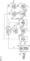
- Fig. 1 is a schematic diagram of a hydrocarbon production apparatus 1 according to an embodiment.
- the hydrocarbon production apparatus 1 includes a reverse shift reaction unit 2, a hydrocarbon production unit 4, a gas-liquid separation unit 6, a catalytic reaction unit 8, a first separation unit 10, a second separation unit 12, a third separation unit 14, a fourth separation unit 16, and a fifth separation unit 18.
- the reverse shift reaction unit 2 is disposed upstream of the hydrocarbon production unit 4.
- the fourth separation unit 16 is disposed between the reverse shift reaction unit 2 and the hydrocarbon production unit 4.
- the gas-liquid separation unit 6 is disposed downstream of the hydrocarbon production unit 4.
- the first separation unit 10 is disposed between the gas-liquid separation unit 6 and the reverse shift reaction unit 2, and between the gas-liquid separation unit 6 and the catalytic reaction unit 8.
- the second separation unit 12 is disposed in parallel with the first separation unit 10 between the gas-liquid separation unit 6 and the catalytic reaction unit 8.
- the third separation unit 14 is disposed between the second separation unit 12 and the catalytic reaction unit 8.
- the fifth separation unit 18 is disposed between the catalytic reaction unit 8 and the hydrocarbon production unit 4.
- the reverse shift reaction unit 2 receives supply of carbon dioxide and hydrogen as source gases. Carbon dioxide is reduced to carbon monoxide by a reverse shift reaction by using carbon dioxide and hydrogen to obtain a synthesis gas containing carbon monoxide and unreacted hydrogen.
- the reverse shift reaction unit 2 of the present embodiment receives supply of hydrogen from a water electrolysis module 20.
- the water electrolysis module 20 is illustrated as an external device with respect to the hydrocarbon production apparatus 1, but the water electrolysis module 20 may be incorporated in the hydrocarbon production apparatus 1.
- the water electrolysis module 20 is an electrolyzer that generates hydrogen and oxygen by electrolysis of water.
- the water electrolysis module 20 has a structure in which an oxygen generating electrode having a catalyst such as iridium or platinum and a hydrogen generating electrode having a catalyst such as platinum are separated from each other by a membrane having proton conductivity. That is, the water electrolysis module 20 is a solid polymer water electrolysis module.
- Other examples of the water electrolysis module 20 include alkaline water electrolysis module and a solid oxide water electrolysis module. The reactions during water electrolysis in the solid polymer water electrolysis module are as shown in the following Formulas (1) and (2).
- the water electrolysis module 20 receives supply of electric power necessary for water electrolysis from a power supply device (not illustrated).
- the power supply device include a power generation device that generates power using renewable energy, such as a wind power generation device or a solar power generation device. This makes it possible to reduce the emission amount of carbon dioxide associated with the generation of hydrogen and the production of a hydrocarbon having 5 or more carbon atoms (hereinafter, appropriately referred to as "C5+ component") as a target substance.
- the power supply device is not limited to a power generation device using renewable energy, and may be a system power supply, a power storage device storing electric power from the renewable energy power generation device and/or the system power supply, or the like. A combination of two or more of these devices may be used.
- the power supply device is preferably a power generation device using renewable energy.
- the emission amount of carbon dioxide associated with these power generation and power storage is equal to or less than the emission amount of carbon dioxide in the power generation device using renewable energy.
- the reverse shift reaction unit 2 of the present embodiment receives supply of carbon dioxide from a carbon dioxide recovery unit 22.
- the carbon dioxide recovery unit 22 is illustrated as an external device with respect to the hydrocarbon production apparatus 1, but the carbon dioxide recovery unit 22 may be incorporated in the hydrocarbon production apparatus 1. It is not meant that the entire hydrocarbon production apparatus 1 is one reactor.
- the carbon dioxide recovery unit 22 can recover, for example, carbon dioxide from the atmosphere by direct air capture (DAC) or the like.
- the carbon dioxide recovery unit 22 can separate and recover carbon dioxide from exhaust gas discharged from thermal power generation, a chemical plant, or the like by a chemical adsorption method or the like.
- DAC direct air capture
- the reverse shift reaction unit 2 receives supply of carbon dioxide from the carbon dioxide recovery unit 22, reduction of carbon dioxide in the atmosphere or the exhaust gas can be expected.
- the consumption of fossil fuel associated with the production of the C5+ component can be reduced.
- a reverse shift reaction shown in the following Formula (3) occurs to reduce carbon dioxide to carbon monoxide.
- a synthesis gas containing at least carbon monoxide and unreacted hydrogen is obtained.
- Water generated by the reverse shift reaction is also contained in the synthesis gas.
- Unreacted carbon dioxide may also be contained in the synthesis gas.
- the reaction temperature in the reverse shift reaction unit 2 is, for example, 290°C or higher and 1100°C or lower, preferably 700°C or higher and 1100°C or lower, and more preferably 700°C or higher and 950°C or lower.
- the reverse reaction of Formula (3) is called a water-gas-shift reaction.
- a catalyst for the reverse shift reaction a catalyst for a water-gas-shift reaction may be used.
- the reaction temperature of 700°C or higher is much higher than the temperature in a general water-gas-shift reaction. Therefore, when the reaction temperature is set to a high temperature of 700°C or higher, a general water-gas-shift catalyst is not suitable for use.
- the reverse shift reaction unit 2 of the present embodiment contains a composite oxide having a perovskite structure ABO 3 as a reverse shift catalyst.
- A is an alkaline earth metal selected from the group consisting of calcium (Ca), strontium (Sr), and barium (Ba), and is preferably barium.
- B is a metal selected from the group consisting of titanium (Ti), aluminum (Al), zirconium (Zr), iron (Fe), tungsten (W), and molybdenum (Mo), and is preferably zirconium.
- the reverse shift catalyst does not have an acid point that cleaves a bond between carbon atoms of a hydrocarbon and does not have a hydrogen dissociation ability that cleaves a bond between hydrogen atoms of hydrogen.
- the reverse shift catalyst having such characteristics can be screened, for example, by checking that a hydrocarbon having 8 carbon atoms by a dimerization reaction and isobutane by a hydrogenation reaction are not generated in a catalytic reaction using a mixed gas composed of isobutene and hydrogen.
- an atomic absorption spectrophotometer it is preferable to use an atomic absorption spectrophotometer, a Fourier transform infrared spectrophotometer, or the like to measure whether or not the source gas of the reverse shift reaction contains a metal component. It is preferable to install a filter capable of removing fine powder of a carbonized metal generated by carburization and an adsorbent capable of removing a metal carbonyl on a recycle line through which carbon monoxide flows.
- the filter is preferably made of ceramic, and the adsorbent is preferably Y-type zeolite.
- a carbon dioxide removal device may be installed between the reverse shift reaction unit 2 and the hydrocarbon production unit 4 in order to reduce the concentration of carbon dioxide in the synthesis gas.
- a CO/(CO+CO 2 ) ratio at the outlet of the reverse shift reaction unit 2 can be improved.
- the CO/(CO+CO 2 ) ratio is a value calculated from the carbon monoxide concentration and the carbon dioxide concentration at the outlet of the reverse shift reaction unit 2. That is, the CO/(CO+CO 2 ) ratio is a ratio at which carbon dioxide of the raw material is converted (reduced) to carbon monoxide.
- the carbon dioxide concentration at the outlet of the reverse shift reaction unit 2 can be reduced.
- the partial pressure of the synthesis gas composed of carbon monoxide and hydrogen in the hydrocarbon production unit 4 can be increased to improve the carbon monoxide conversion rate and the selectivity of the C5+ component.
- the heat energy required for the carbon dioxide removal device can be supplied from the hydrocarbon production unit 4 using the FT reaction which is an exothermic reaction. This makes it possible to reduce the energy required for the production of a hydrocarbon and to improve the production efficiency of the C5+ component as a target substance.
- the reverse shift reaction By performing the reverse shift reaction at a high temperature of 700°C or higher, generation of oxygenated hydrocarbon or the like can be suppressed. This makes it possible to suppress the oxygenated hydrocarbon as an impurity from being contained in by-product water. Therefore, the water separated by the fourth separation unit 16 located downstream of the reverse shift reaction unit 2 can be recycled to the water electrolysis module 20 without being subjected to a purification treatment (removal of oxygenated impurities).
- a water purification treatment can be performed by supplying the water separated by the fourth separation unit 16 to the third separation unit 14 described below.
- the off-gas of the hydrocarbon production unit 4 is recycled to improve the production efficiency of the C5+ component, but energy is also required for this recycling.
- the amount of recycled off-gas can be suppressed by increasing the yield of the liquid component by improvement of the CO/(CO+CO 2 ) ratio. Therefore, it is possible to reduce the auxiliary power required for recycling, the energy required for separating the off-gas, the heat amount required for the catalytic reaction at the recycling destination, and the like. As a result, improvement in production efficiency can be expected as the entire process of producing the C5+ component.
- the synthesis gas flowing out of the reverse shift reaction unit 2 is sent to the fourth separation unit 16.
- the fourth separation unit 16 can be constituted by a known gas-liquid separation unit, and separates water from the synthesis gas.
- the water separated by the fourth separation unit 16 is supplied to the water electrolysis module 20 and used for generation of hydrogen.
- the water separated by the fourth separation unit 16 is supplied to the catalytic reaction unit 8 and used for the catalytic reaction in the catalytic reaction unit 8. This makes it possible to improve the production efficiency of the C5+ component.
- the recycling of the water separated from the synthesis gas may be performed on only one of the water electrolysis module 20 and the catalytic reaction unit 8, or may not be performed on both of them.
- the synthesis gas from which water is separated by the fourth separation unit 16 is sent to the hydrocarbon production unit 4.
- the hydrocarbon production unit 4 produces a C5+ component as a target substance by using the supplied synthesis gas.
- the C5+ component is, for example, normal paraffin.
- the hydrocarbon production unit 4 of the present embodiment is constituted by a known FT reactor.
- a FT reactor a tubular fixed bed reactor, a slurry bed reactor, or the like can be used.
- the FT reaction shown in Formula (4) described below occurs, and a C5+ component is generated by carbon-carbon chain growth.
- a catalyst for FT reaction a cobalt catalyst, a precipitated iron catalyst, a ruthenium catalyst, or the like can be used.
- the proportion of a reaction intermediate having n carbon atoms to be heavy into a reaction intermediate having n + 1 carbon atoms by carbon-carbon chain growth is represented by a chain growth probability ⁇ .
- ⁇ varies depending on the type of catalyst and reaction conditions, and is preferably 0.75 to 0.95 and more preferably 0.85 to 0.95.
- n of the C5+ component contained in an amount of 0.1 mol% or more is an integer of 5 to 60.
- C4-component a gaseous light hydrocarbon having 4 or less carbon atoms at normal temperature and normal pressure
- methane, ethane, propane, and butane are also produced as by-products.
- the effluent from the hydrocarbon production unit 4 is sent to the gas-liquid separation unit 6.
- the effluent may contain not only a C5+ component and a C4- component, but also water and oxygenated hydrocarbon (such as C n H m O) as other by-products, unreacted hydrogen, carbon monoxide, carbon dioxide, and the like.
- the oxygenated hydrocarbon is a hydrocarbon compound containing oxygen, and is hydrophilic and easily dissolved in water. Examples of the oxygenated hydrocarbon include alcohols, carboxylic acids, esters, ethers, and ketones.
- the gas-liquid separation unit 6 can be constituted by a known gas-liquid separation unit, and separates a liquid component and a gas component from the effluent.
- the gas-liquid separation is preferably performed in two stages of high temperature and low temperature. This makes it possible to prevent the gas-liquid separation unit 6 from being blocked by a heavy hydrocarbon.
- high-temperature gas-liquid separation can be performed at 80°C
- low-temperature gas-liquid separation can be performed at 40°C.
- the temperature at the time of gas-liquid separation may be increased to a temperature lower than the boiling point temperature of water at the partial pressure of water by 20°C.
- the liquid component contains an oily component containing a C5+ component and an aqueous component containing water and an oxygenated hydrocarbon.
- the gas component contains hydrogen, carbon monoxide, carbon dioxide, and a C4- component.
- the gas component separated by the gas-liquid separation unit 6 is sent to the first separation unit 10.
- the first separation unit 10 separates hydrogen and carbon dioxide, and a C4- component from the gas component (first separation step). Carbon monoxide is included on the side of the C4- component. Carbon monoxide may be included on the side of the hydrogen and the carbon dioxide.
- the first separation unit 10 performs separation by using at least one of a pressure swing adsorption (PSA) method and a membrane separation method.
- PSA pressure swing adsorption
- the first separation unit 10 uses a membrane separation method
- the first separation unit 10 includes at least one of a polyimide film, a carbon film obtained by carbonizing the polyimide film, and a metal film containing Pd.
- the hydrogen and carbon dioxide separated by the first separation unit 10 are sent to the reverse shift reaction unit 2.
- the reverse shift reaction unit 2 receives supply of the hydrogen and carbon dioxide separated by the first separation unit 10 and also uses the hydrogen and carbon dioxide for generation of the synthesis gas. This makes it possible to increase the utilization rate of the hydrogen and carbon dioxide supplied as raw materials and to improve the production efficiency of the C5+ component.
- the recycled gas supplied to the reverse shift reaction unit 2 contains a large amount of compounds other than hydrogen and carbon dioxide, which are reactants in the reverse shift reaction unit 2, a reverse reaction may occur aiming at an equilibrium composition in the reverse shift reaction unit 2. As a result, the amount of carbon monoxide produced can be reduced.
- the reverse reaction can be suppressed. Therefore, the production efficiency of the C5+ component can be further improved.
- the C4- component and carbon monoxide separated by the first separation unit 10 are sent to the catalytic reaction unit 8.
- the catalytic reaction unit 8 receives supply of the C4- component separated by the first separation unit 10 and generates hydrogen and carbon monoxide by using the C4-component.
- the C4- component is sent to the reverse shift reaction unit 2 without providing the first separation unit 10
- the C4- component is hardly reacted in the reverse shift reaction unit 2, and thus is accumulated in the system.
- the partial pressure of the synthesis gas in the system decreases, and the reaction in the hydrocarbon production unit 4 may be inhibited.
- the C4- component separated by the first separation unit 10 is sent to the catalytic reaction unit 8 and used for generation of hydrogen and carbon monoxide. This makes it possible to further improve the production efficiency of the C5+ component. Carbon monoxide is also used for the reaction in the catalytic reaction unit 8.
- Carbon dioxide is not involved in the reaction in the catalytic reaction unit 8. Carbon dioxide is generally a non-flammable substance. Therefore, even when the catalytic reaction unit 8 performs a partial oxidation reaction or an autothermal reforming reaction described below, carbon dioxide is not used for combustion. Therefore, when carbon dioxide is sent to the catalytic reaction unit 8 without providing the first separation unit 10, the carbon dioxide is also heated at the time of increasing the temperature of the catalytic reaction unit 8 to the reaction temperature of the catalytic reaction, so that the required energy may be increased. On the other hand, in the present embodiment, the carbon dioxide separated by the first separation unit 10 is sent to the reverse shift reaction unit 2 and used for generation of the synthesis gas. This makes it possible to suppress an increase in required energy in the catalytic reaction unit 8 and to further improve the production efficiency of the C5+ component.
- the catalytic reaction unit 8 generates hydrogen and carbon monoxide from the C4- component by any of a steam reforming reaction, a partial oxidation reaction, and an autothermal reforming reaction.
- the catalytic reaction unit 8 generates hydrogen and carbon monoxide from the C4- component by a reforming reaction (at least one of a steam reforming reaction and an autothermal reforming reaction).
- a reforming reaction at least one of a steam reforming reaction and an autothermal reforming reaction.
- the catalytic reaction unit 8 When the catalytic reaction unit 8 generates hydrogen and carbon monoxide from the C4- component by a steam reforming reaction, the catalytic reaction unit 8 can be constituted by a known steam reformer. In this case, as an example, the catalytic reaction unit 8 generates methane from the C4- component by a preceding stage reaction in which a steam reforming reaction is performed at a first temperature, and generates carbon monoxide and hydrogen from the methane by a subsequent stage reaction in which a steam reforming reaction is performed at a second temperature higher than the first temperature.
- the catalytic reaction unit 8 may include a reactor for the preceding stage reaction and a reactor for the subsequent stage reaction, and may change a temperature in one reactor from the first temperature to the second temperature.
- the first temperature is, for example, 450 to 600°C and preferably 450 to 500°C.
- the second temperature is, for example, 750°C or higher.
- a difference in reaction temperature between the preceding stage and the subsequent stage is preferably 150°C or higher and more preferably 250°C or higher.
- O/C ratio oxygen/carbon ratio
- the O/C ratio is a ratio of the number of moles (O) of oxygen atoms to be supplied into the catalytic reaction unit 8 to the number of moles (C) of carbon atoms to be supplied into the catalytic reaction unit 8.
- the number of moles of oxygen atoms is equal to the number of moles of steam, that is, the O/C ratio is equal to the S/C ratio (steam/carbon ratio).
- the heat amount required for heating the water increases, and thus the energy efficiency required for the production of the C5+ component decreases.
- the above-described two-stage reforming reaction it is possible to suppress an increase in the supply amount of water for the purpose of suppressing coke deposition. Therefore, the energy required for the production of the C5+ component can be reduced, and the production efficiency of the C5+ component can be improved.
- the first temperature is set so that a pre-reforming reaction shown in the following Formulas (5) to (7) occurs as the preceding stage reaction to mainly generate methane.
- the S/C ratio is preferably 2.5 to 3.0.
- the reaction shown in Formula (7) is an exothermic reaction. Therefore, with the same composition and pressure, the lower the temperature, the higher the yield of methane.
- the second temperature is set so that a reaction shown in the following Formula (8) occurs as the subsequent stage reaction to produce a synthesis gas containing carbon monoxide and hydrogen.
- the reaction shown in Formula (8) is a reverse reaction of Formula (7) and is an endothermic reaction. Therefore, with the same composition and pressure, the higher the temperature, the higher the yield of carbon monoxide and hydrogen.
- the S/C ratio at the second temperature is 1.0 to 2.5. It is preferable that the S/C ratio can be adjusted by not adding water consumed in the preceding stage reaction.
- the C4- component is expressed as C n H m , n is an integer of 1 to 4, and m is an integer of 4 to 10. In the following reaction formulas, the C4- component is expressed in the same manner.
- the catalytic reaction unit 8 When the catalytic reaction unit 8 generates hydrogen and carbon monoxide from the C4- component by an autothermal reforming reaction, the catalytic reaction unit 8 can be constituted by a known autothermal reformer. In this case, in the catalytic reaction unit 8, first, a reaction shown in the following Formula (9) occurs, and subsequently, a reaction shown in the following Formula (10) occurs. The reaction shown in Formula (9) is an exothermic reaction. On the other hand, the reaction shown in Formula (10) is an endothermic reaction. Heat necessary for the reaction shown in Formula (10) is covered by heat generated by the reaction shown in Formula (9). In the reaction shown in Formula (9), the by-product oxygen generated by the water electrolysis module 20 can be used. C n H m +(n/2)O 2 ⁇ nCO+(m/2)H 2 (9) C n H m +nH 2 O ⁇ nCO+(n+m/2)H 2 (10)
- the catalytic reaction unit 8 When the catalytic reaction unit 8 generates hydrogen and carbon monoxide from the C4- component by a partial oxidation reaction, the catalytic reaction unit 8 can be constituted by a known partial oxidation reactor. In this case, in the catalytic reaction unit 8, a reaction shown in the following Formula (11) occurs. In the reaction shown in Formula (11), the by-product oxygen generated by the water electrolysis module 20 can be used. C n H m +(n/2)O 2 ⁇ nCO+(m/2)H 2 (11)
- a preliminary reformer (not illustrated) for performing the above-described pre-reforming reaction may be provided between the first separation unit 10 and the catalytic reaction unit 8.
- This pre-reforming reaction is performed at the above-described first temperature.
- the reactions shown in the above Formulas (5) to (7) occur, the C4- component sent from the first separation unit 10 is reformed into methane by the preliminary reformer, and the methane can be subjected to the autothermal reforming reaction.
- the effluent from the catalytic reaction unit 8 is sent to the fifth separation unit 18.
- This effluent may contain unreacted water as well as hydrogen and carbon monoxide.
- the fifth separation unit 18 can be constituted by a known gas-liquid separation unit, and separates hydrogen and carbon monoxide, and water from the effluent.
- the water separated by the fifth separation unit 18 is sent to the catalytic reaction unit 8 and reused for the reaction in the catalytic reaction unit 8.
- the supply of the water from the fifth separation unit 18 to the catalytic reaction unit 8 is omitted.
- the supply of the water from the fourth separation unit 16 described above and the supply of the aqueous component from the third separation unit 14 described below are also omitted.
- the fifth separation unit 18 is omitted and the effluent from the catalytic reaction unit 8 is sent to the fourth separation unit 16.
- the effluent from the catalytic reaction unit 8 may contain an oxygenated hydrocarbon. Therefore, it is desirable that the fifth separation unit 18 is provided separately from the fourth separation unit 16, and water is looped between the catalytic reaction unit 8 and the fifth separation unit 18.
- the hydrogen and carbon monoxide separated by the fifth separation unit 18 are sent to the hydrocarbon production unit 4.
- the hydrocarbon production unit 4 receives supply of the hydrogen and carbon monoxide generated by the catalytic reaction unit 8 and also uses the hydrogen and carbon monoxide for generation of the C5+ component. This makes it possible to improve the utilization rate of the hydrogen and carbon dioxide supplied as raw materials and to improve the production efficiency of the C5+ component.
- the liquid component separated by the gas-liquid separation unit 6 is sent to the second separation unit 12.
- the second separation unit 12 can be constituted by a known oil-water separator, and separates an oily component and an aqueous component from the liquid component (second separation step).
- the C5+ component contained in the oily component separated by the second separation unit 12 is subjected to an upgrade treatment by catalytic reforming, hydrogenolysis, hydrogenation purification, alkylation, isomerization, or the like as necessary, and is used, for example, as a substitute for jet fuel, gasoline, kerosene, or the like.
- the C4- component by-produced by the upgrade apparatus may be returned to the first separation unit 10. This makes it possible to enhance the production efficiency as a substitute for jet fuel or the like.
- a part of the aqueous component separated by the second separation unit 12 is sent to the catalytic reaction unit 8.
- the catalytic reaction unit 8 receives supply of the aqueous component separated by the second separation unit 12, and the aqueous component is also used for generation of hydrogen and carbon monoxide. This makes it possible to convert water in the aqueous component into hydrogen in the catalytic reaction unit 8. Therefore, since the amount of hydrogen supplied as a raw material can be reduced, the production efficiency of the C5+ component can be improved.
- the oxygenated hydrocarbon in the aqueous component can be converted into carbon monoxide in the catalytic reaction unit 8. This also makes it possible to improve the production efficiency of the C5+ component.
- a part of the aqueous component separated by the second separation unit 12 is sent to the water electrolysis module 20.
- the water electrolysis module 20 receives supply of the aqueous component separated by the second separation unit 12 and generates hydrogen by using the aqueous component.
- the aqueous component separated by the second separation unit 12 is sent to the catalytic reaction unit 8 and the water electrolysis module 20 through the third separation unit 14.
- the third separation unit 14 separates at least a part of water from the aqueous component.
- water substantially free of oxygenated hydrocarbon and water in which the oxygenated hydrocarbon is concentrated are obtained. That is, the water purification treatment is performed.
- the third separation unit 14 performs separation by using at least one of a pressure swing adsorption (PSA) method, a precision distillation method, and a membrane separation method.
- PSA pressure swing adsorption
- the third separation unit 14 uses a membrane separation method
- the third separation unit 14 includes at least one of a reverse osmosis membrane, a zeolite membrane, and a carbon membrane.
- the water separated by the third separation unit 14, that is, water from which oxygenated hydrocarbon has been removed, in other words, purified water is supplied to the water electrolysis module 20.
- the water electrolysis module 20 receives supply of the water separated by the third separation unit 14 and generates hydrogen by using the water.
- catalyst deterioration in the water electrolysis module 20 can be suppressed. Therefore, the use period of the water electrolysis module 20 can be extended, and the production efficiency of the C5+ component can be improved.
- the aqueous component from which water is separated by the third separation unit 14, in other words, the water in which the oxygenated hydrocarbon is concentrated is supplied to the catalytic reaction unit 8.
- the catalytic reaction unit 8 receives supply of the aqueous component from which water is separated by the third separation unit 14, and the aqueous component is used for generation of hydrogen and carbon monoxide.
- the catalytic reaction unit 8 generates hydrogen and carbon monoxide from the oxygenated hydrocarbon by the reforming reaction.
- the catalytic reaction unit 8 When the catalytic reaction unit 8 generates hydrogen and carbon monoxide from the oxygenated hydrocarbon by a steam reforming reaction, the catalytic reaction unit 8 can be constituted by a known steam reformer.
- the catalytic reaction unit 8 generates methane from the oxygenated hydrocarbon by a preceding stage reaction in which a steam reforming reaction is performed at a first temperature, and generates carbon monoxide and hydrogen from the methane by a subsequent stage reaction in which a steam reforming reaction is performed at a second temperature higher than the first temperature.
- the first temperature is, for example, 450 to 600°C and preferably 450 to 500°C.
- the second temperature is, for example, 750°C or higher.
- a difference in reaction temperature between the preceding stage and the subsequent stage is preferably 150°C or higher and more preferably 250°C or higher.
- the oxygenated hydrocarbon By converting the oxygenated hydrocarbon into mainly methane in the preceding stage reaction and then subjecting the methane to the subsequent stage reaction, it is possible to produce hydrogen and carbon monoxide while suppressing catalyst deterioration and the like due to coke deposition and suppressing an increase in the S/C ratio, as in the case of the C4- component. This makes it possible to improve the production efficiency of the C5+ component.
- the reaction temperature at the preceding stage can be lower than the reaction temperature at the subsequent stage.
- the reaction temperature at the preceding stage can be further lowered as compared with the case of the C4- component. This makes it possible to reduce the energy required for the production of the C5+ component and to further improve the production efficiency of the C5+ component.
- the first temperature is set so that a pre-reforming reaction shown in the following Formulas (12) to (14) occurs as the preceding stage reaction to mainly generate methane.
- the S/C ratio is preferably 2.5 to 3.0.
- the reaction shown in Formula (14) is an exothermic reaction. Therefore, with the same composition and pressure, the lower the temperature, the higher the yield of methane.
- the second temperature is set so that a reaction shown in the following Formula (15) occurs as the subsequent stage reaction to produce a synthesis gas containing carbon monoxide and hydrogen.
- the reaction shown in Formula (15) is a reverse reaction of Formula (14) and is an endothermic reaction. Therefore, with the same composition and pressure, the higher the temperature, the higher the yield of carbon monoxide and hydrogen.
- the S/C ratio at the second temperature is 1.0 to 2.5. It is preferable that the S/C ratio can be adjusted by not adding water consumed in the preceding stage reaction.
- n is, for example, an integer of 1 to 7
- m is, for example, an integer of 4 to 16.
- the numerical values of n and m in the oxygenated hydrocarbon are the same.
- the catalytic reaction unit 8 When the catalytic reaction unit 8 generates hydrogen and carbon monoxide from the oxygenated hydrocarbon by an autothermal reforming reaction, the catalytic reaction unit 8 can be constituted by a known autothermal reformer. In this case, in the catalytic reaction unit 8, first, a reaction shown in the following Formula (16) occurs, and subsequently, a reaction shown in the following Formula (17) occurs.
- the reaction shown in Formula (16) is an exothermic reaction.
- the reaction shown in Formula (17) is an endothermic reaction. Heat necessary for the reaction shown in Formula (17) is covered by heat generated by the reaction shown in Formula (16).
- the by-product oxygen generated by the water electrolysis module 20 can be used.
- a preliminary reformer (not illustrated) for performing the above-described pre-reforming reaction may be provided between the third separation unit 14 and the catalytic reaction unit 8.
- This pre-reforming reaction is performed at the above-described first temperature.
- the reactions shown in the above Formulas (12) to (14) occur, the oxygenated hydrocarbon sent from the third separation unit 14 is reformed into methane by the steam reformer, and the methane can be subjected to the autothermal reforming reaction.
- a dehydration reaction shown in the following Formula (18) and a dehydration condensation reaction shown in the following Formula (19) occur as side reactions, and water can be generated from a hydrogencontaining hydrocarbon.
- the numerical range of a is similar to n
- the numerical range of b is similar to m.
- the amount of water to be supplied to the catalytic reaction unit 8 is reduced by separating at least a part of water by the third separation unit 14. This makes it possible to reduce the S/C ratio in the catalytic reaction unit 8.
- the by-product water can be used for suppressing coke deposition. Therefore, while reducing the supply amount of water to the catalytic reaction unit 8 to reduce the S/C ratio, coke deposition can be suppressed to suppress catalyst deterioration in the catalytic reaction unit 8. As a result, the use period of the catalytic reaction unit 8 can be extended, and the production efficiency of the C5+ component can be improved.
- the energy efficiency required for the production of the C5+ component can be expressed by the following Formula (20) .
- Energy efficiency Calorific value of the obtained C 5 + component / Calorific value of consumed raw material hydrogen + Required heat amount on premise of heat recovery for production + Power required for production of consumed raw material hydrogen + Heat amount and power required for recovery of consumed raw material carbon dioxide
- the "required heat amount on premise of heat recovery for production" in Formula (20) means a heat amount added from the outside of the system on the premise that heat of a temperature difference between the inlet gas and the outlet gas in each reactor is recovered and the recovered heat is reused for the reaction.
- the raw material to be supplied to the reverse shift reaction unit 2 needs to be heated to the reaction temperature (for example, 800°C) in the reverse shift reaction unit 2. Since the reverse shift reaction is an endothermic reaction, it is necessary to add heat.
- the synthesis gas obtained in the reverse shift reaction unit 2 in order to subject the synthesis gas obtained in the reverse shift reaction unit 2 to a gas-liquid separation treatment in the fourth separation unit 16, it is necessary to cool the synthesis gas. Therefore, heat of the synthesis gas (outlet gas) discharged in the reverse shift reaction unit 2 is recovered by a heat exchanger, and the recovered heat is transferred to the raw material (inlet gas). This makes it possible to reduce the fuel of a heating furnace for heating the raw material and the power of a chiller for cooling the synthesis gas.
- the carbon dioxide recovery unit 22 separates and recovers carbon dioxide by a chemical adsorption method or the like, heat is required to dissipate the adsorbed carbon dioxide.
- the FT reaction occurring in the hydrocarbon production unit 4 is an exothermic reaction. Therefore, the heat generated in the hydrocarbon production unit 4 can be recovered by a heat exchanger, and the recovered heat can be used for the dissipation of carbon dioxide in the carbon dioxide recovery unit 22.
- the heat that is insufficient even if the heat is recovered as much as possible needs to be generated in a heating furnace.
- the heat generated in this heating furnace corresponds to the "required heat amount on premise of heat recovery for production".
- the catalytic reaction unit 8 is constituted by an autothermal reformer, the required heat amount can be reduced as compared with a case where the catalytic reaction unit 8 is constituted by a steam reformer.
- the catalytic reaction unit 8 is constituted by an autothermal reformer
- hydrogen and carbon dioxide are also supplied to the catalytic reaction unit 8 without providing the first separation unit 10
- heat is required for heating the carbon dioxide, and it is difficult to cover the reaction heat required for the reforming reaction by partial oxidation of the C4- component.
- the insufficient reaction heat is covered by the combustion of hydrogen sent to the catalytic reaction unit 8 together with carbon dioxide.
- the catalytic reaction unit 8 is constituted by a steam reformer, combustion of hydrogen does not occur in the catalytic reaction unit 8, and by-product water is not generated. Therefore, even when hydrogen is supplied to the catalytic reaction unit 8, the water recycled from the hydrocarbon production unit 4 is used for the reforming reaction in the catalytic reaction unit 8. Therefore, it is possible to reduce the H 2/ CO 2 ratio of the fresh feed as compared with a case where the catalytic reaction unit 8 is constituted by an autothermal reformer. When the H 2/ CO 2 ratio of the fresh feed can be reduced, the power required for the production of hydrogen can be reduced. Therefore, a decrease in energy efficiency shown in Formula (20) can be suppressed.
- the catalytic reaction unit 8 when the catalytic reaction unit 8 is constituted by a steam reformer, the effect of improving the production efficiency of the C5+ component by recycling the aqueous component can be more strongly exhibited.
- the catalytic reaction unit 8 is constituted by an autothermal reformer, by combining the first separation unit 10, the improving effect can be more easily exhibited.
- the molar ratio (CO/H 2 ratio) of carbon monoxide and hydrogen to be supplied to the hydrocarbon production unit 4 is preferably 1.5 or more and 4.0 or less, more preferably 2.0 or more and 3.5 or less, and still more preferably 2.2 or more and 3.0 or less.
- the S/C ratio in the preceding stage reaction is preferably 3.0 or more and 6.0 or less.
- the S/C ratio in the subsequent stage reaction is preferably 0.5 or more and 3.0 or less and more preferably 1.0 or more and 2.5 or less.
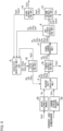
- Fig. 2 is a schematic diagram of a hydrocarbon production apparatus according to a comparative example.
- Fig. 3 is a schematic diagram of a hydrocarbon production apparatus according to Test Example 1.
- Fig. 4 is a schematic diagram of a hydrocarbon production apparatus according to Test Example 2.
- Fig. 5 is a schematic diagram of a hydrocarbon production apparatus according to Test Example 3.
- Fig. 6 is a schematic diagram of a hydrocarbon production apparatus according to Test Example 4.
- the hydrocarbon production apparatus does not include the catalytic reaction unit 8 and the first separation unit 10. Therefore, the gas component separated by the gas-liquid separation unit 6 is directly recycled to the reverse shift reaction unit 2.
- the third separation unit 14 is also not provided. Therefore, separation of water from the aqueous component separated by the second separation unit 12, that is, a concentration treatment of the oxygenated hydrocarbon is not performed.
- the hydrocarbon production apparatus does not include the first separation unit 10. Therefore, the gas component separated by the gas-liquid separation unit 6 is directly recycled to the catalytic reaction unit 8.
- the catalytic reaction unit 8 is constituted by an autothermal reformer (ATR).
- ATR autothermal reformer
- the hydrogen, carbon monoxide, and carbon dioxide separated by the fifth separation unit 18 are recycled to the reverse shift reaction unit 2.
- the third separation unit 14 is provided. Therefore, the aqueous component separated by the second separation unit 12 is subjected to a concentration treatment of the oxygenated hydrocarbon.
- the water in which the oxygenated hydrocarbon is concentrated is recycled to the catalytic reaction unit 8.
- the hydrocarbon production apparatus includes the first separation unit 10.
- the C4- component and carbon monoxide separated by the first separation unit 10 are recycled to the catalytic reaction unit 8.
- the hydrogen and carbon dioxide separated by the first separation unit 10 are recycled to the reverse shift reaction unit 2.
- the catalytic reaction unit 8 is constituted by an autothermal reformer.
- the hydrogen and carbon monoxide separated by the fifth separation unit 18 are recycled to the hydrocarbon production unit 4.
- the third separation unit 14 is also provided. Therefore, the aqueous component separated by the second separation unit 12 is subjected to a concentration treatment of the oxygenated hydrocarbon.
- the water in which the oxygenated hydrocarbon is concentrated is recycled to the catalytic reaction unit 8.
- the hydrocarbon production apparatus does not include the first separation unit 10. Therefore, the gas component separated by the gas-liquid separation unit 6 is directly recycled to the catalytic reaction unit 8.
- the catalytic reaction unit 8 is constituted by a steam reformer (SR).
- SR steam reformer
- the hydrogen, carbon monoxide, and carbon dioxide separated by the fifth separation unit 18 are recycled to the reverse shift reaction unit 2.
- the third separation unit 14 is provided. Therefore, the aqueous component separated by the second separation unit 12 is subjected to a concentration treatment of the oxygenated hydrocarbon.
- the water in which the oxygenated hydrocarbon is concentrated is recycled to the catalytic reaction unit 8.
- the hydrocarbon production apparatus includes the first separation unit 10.
- the C4- component and carbon monoxide separated by the first separation unit 10 are recycled to the catalytic reaction unit 8.
- the hydrogen and carbon dioxide separated by the first separation unit 10 are recycled to the reverse shift reaction unit 2.
- the catalytic reaction unit 8 is constituted by a steam reformer.
- the hydrogen and carbon monoxide separated by the fifth separation unit 18 are recycled to the hydrocarbon production unit 4.
- the third separation unit 14 is also provided. Therefore, the aqueous component separated by the second separation unit 12 is subjected to a concentration treatment of the oxygenated hydrocarbon.
- the water in which the oxygenated hydrocarbon is concentrated is recycled to the catalytic reaction unit 8.
- a C5+ component was produced under predetermined conditions by using the hydrocarbon production apparatuses of the comparative example and each Test Example.
- the energy efficiency (see Formula (20)) at that time was calculated.
- the reaction conditions at the time of calculating the energy efficiency were as follows. In addition to the following reaction conditions, the H 2/ CO 2 ratio of the fresh feed was adjusted so that the H 2/ CO 2 ratio (molar ratio) to be supplied to the reverse shift reaction unit maintained 3. Except for the FT reaction in the hydrocarbon production unit, each reaction was allowed to proceed until the equilibrium composition was achieved.
- Embodiments may be identified by the items described below.
- a hydrocarbon production apparatus (1) including:
- a hydrocarbon production method including:
- the liquid component contains an oily component containing a hydrocarbon having 5 or more carbon atoms (C5+) and an aqueous component containing water,
- the present invention can be used in a hydrocarbon production apparatus and a hydrocarbon production method.
Applications Claiming Priority (2)
| Application Number | Priority Date | Filing Date | Title |
|---|---|---|---|
| JP2021100351A JP2022191870A (ja) | 2021-06-16 | 2021-06-16 | 炭化水素製造装置および炭化水素製造方法 |
| PCT/JP2022/022612 WO2022264836A1 (fr) | 2021-06-16 | 2022-06-03 | Appareil et procédé de production d'hydrocarbures |
Publications (1)
| Publication Number | Publication Date |
|---|---|
| EP4357327A1 true EP4357327A1 (fr) | 2024-04-24 |
Family
ID=84526209
Family Applications (1)
| Application Number | Title | Priority Date | Filing Date |
|---|---|---|---|
| EP22824828.2A Pending EP4357327A1 (fr) | 2021-06-16 | 2022-06-03 | Appareil et procédé de production d'hydrocarbures |
Country Status (4)
| Country | Link |
|---|---|
| EP (1) | EP4357327A1 (fr) |
| JP (1) | JP2022191870A (fr) |
| AU (1) | AU2022294462A1 (fr) |
| WO (1) | WO2022264836A1 (fr) |
Families Citing this family (1)
| Publication number | Priority date | Publication date | Assignee | Title |
|---|---|---|---|---|
| JP7361142B2 (ja) | 2022-01-12 | 2023-10-13 | 本田技研工業株式会社 | 燃料合成装置 |
Family Cites Families (4)
| Publication number | Priority date | Publication date | Assignee | Title |
|---|---|---|---|---|
| JP5277364B2 (ja) | 2007-03-30 | 2013-08-28 | 公益財団法人北九州産業学術推進機構 | 一酸化炭素の還元による炭化水素の製造方法 |
| US8184763B2 (en) * | 2009-01-13 | 2012-05-22 | Areva Sa | System and a process for producing at least one hydrocarbon fuel from a carbonaceous material |
| FR2971789B1 (fr) * | 2011-02-22 | 2013-02-22 | Areva | Methode de production de methanol ou d'hydrocarbures a partir d'une matiere carbonee, avec une etape de reformage dont les conditions de fontionnement sont ajustees selectivement |
| WO2016176105A1 (fr) * | 2015-04-29 | 2016-11-03 | Sabic Global Technologies B.V. | Procédés permettant la conversion du co2 en gaz de synthèse |
-
2021
- 2021-06-16 JP JP2021100351A patent/JP2022191870A/ja active Pending
-
2022
- 2022-06-03 AU AU2022294462A patent/AU2022294462A1/en active Pending
- 2022-06-03 WO PCT/JP2022/022612 patent/WO2022264836A1/fr active Application Filing
- 2022-06-03 EP EP22824828.2A patent/EP4357327A1/fr active Pending
Also Published As
| Publication number | Publication date |
|---|---|
| WO2022264836A1 (fr) | 2022-12-22 |
| JP2022191870A (ja) | 2022-12-28 |
| AU2022294462A1 (en) | 2024-01-25 |
Similar Documents
| Publication | Publication Date | Title |
|---|---|---|
| RU2524720C2 (ru) | Комплексная установка для переработки газа | |
| RU2408567C2 (ru) | Синтез метанола | |
| US9067850B2 (en) | Synthesis gas and Fischer Tropsch integrated process | |
| US9085513B2 (en) | Co-production of methanol and urea | |
| US20200087576A1 (en) | Processes and catalysts for reforming of impure methane-containing feeds | |
| KR101717121B1 (ko) | 메탄올 및 암모니아의 공동 제조 | |
| CN110177772B (zh) | 甲醇、氨和尿素的联合生产 | |
| JP2009179591A (ja) | メタノールの製造方法 | |
| EP4357327A1 (fr) | Appareil et procédé de production d'hydrocarbures | |
| CA3171759A1 (fr) | Production d'hydrocarbures | |
| AU2016261285A1 (en) | A novel method for methanol synthesis | |
| EP4357326A1 (fr) | Appareil et procédé de production d'hydrocarbures | |
| US11111142B2 (en) | Processes and catalysts for reforming of impure methane-containing feeds | |
| US20210387934A1 (en) | Methanol production process with higher carbon utilization by co2 recycle | |
| US20240059978A1 (en) | One-step process for the production of hydrocarbons from carbon dioxide | |
| US20220135506A1 (en) | Methanol production process | |
| EA040722B1 (ru) | Способ производства метанола из газообразных углеводородов | |
| WO2023194270A1 (fr) | Procédé de modernisation d'une installation de co-production d'ammoniac et de méthanol | |
| WO2023187147A1 (fr) | Conversion de dioxyde de carbone en essence à l'aide d'e-smr | |
| US20230073089A1 (en) | Co-production of methanol, ammonia and urea | |
| WO2022238672A1 (fr) | Procédé de synthèse de méthanol | |
| JP2022075138A (ja) | 燃料ガスの製造方法 | |
| TW202408921A (zh) | 由合成氣及/或co2所生產之甲醇生產合成氣之技術 | |
| AU2012364340B2 (en) | Co-production of methanol and urea | |
| KR20240005207A (ko) | 암모니아 합성 가스의 제조를 위한 방법 및 촉매 |
Legal Events
| Date | Code | Title | Description |
|---|---|---|---|
| STAA | Information on the status of an ep patent application or granted ep patent |
Free format text: STATUS: THE INTERNATIONAL PUBLICATION HAS BEEN MADE |
|
| PUAI | Public reference made under article 153(3) epc to a published international application that has entered the european phase |
Free format text: ORIGINAL CODE: 0009012 |
|
| STAA | Information on the status of an ep patent application or granted ep patent |
Free format text: STATUS: REQUEST FOR EXAMINATION WAS MADE |
|
| 17P | Request for examination filed |
Effective date: 20231215 |
|
| AK | Designated contracting states |
Kind code of ref document: A1 Designated state(s): AL AT BE BG CH CY CZ DE DK EE ES FI FR GB GR HR HU IE IS IT LI LT LU LV MC MK MT NL NO PL PT RO RS SE SI SK SM TR |