EP4355673B1 - Abwickelvorrichtung und betriebsverfahren zum abwickeln von bahnmaterialien von mutterrollen - Google Patents
Abwickelvorrichtung und betriebsverfahren zum abwickeln von bahnmaterialien von mutterrollen Download PDFInfo
- Publication number
- EP4355673B1 EP4355673B1 EP22735632.6A EP22735632A EP4355673B1 EP 4355673 B1 EP4355673 B1 EP 4355673B1 EP 22735632 A EP22735632 A EP 22735632A EP 4355673 B1 EP4355673 B1 EP 4355673B1
- Authority
- EP
- European Patent Office
- Prior art keywords
- reel
- parent
- web
- unwinder
- guide surface
- Prior art date
- Legal status (The legal status is an assumption and is not a legal conclusion. Google has not performed a legal analysis and makes no representation as to the accuracy of the status listed.)
- Active
Links
Images


Classifications
-
- B—PERFORMING OPERATIONS; TRANSPORTING
- B65—CONVEYING; PACKING; STORING; HANDLING THIN OR FILAMENTARY MATERIAL
- B65H—HANDLING THIN OR FILAMENTARY MATERIAL, e.g. SHEETS, WEBS, CABLES
- B65H19/00—Changing the web roll
- B65H19/10—Changing the web roll in unwinding mechanisms or in connection with unwinding operations
- B65H19/18—Attaching, e.g. pasting, the replacement web to the expiring web
-
- B—PERFORMING OPERATIONS; TRANSPORTING
- B65—CONVEYING; PACKING; STORING; HANDLING THIN OR FILAMENTARY MATERIAL
- B65H—HANDLING THIN OR FILAMENTARY MATERIAL, e.g. SHEETS, WEBS, CABLES
- B65H19/00—Changing the web roll
- B65H19/10—Changing the web roll in unwinding mechanisms or in connection with unwinding operations
- B65H19/105—Opening of web rolls; Removing damaged outer layers; Detecting the leading end of a closed web roll
-
- B—PERFORMING OPERATIONS; TRANSPORTING
- B65—CONVEYING; PACKING; STORING; HANDLING THIN OR FILAMENTARY MATERIAL
- B65H—HANDLING THIN OR FILAMENTARY MATERIAL, e.g. SHEETS, WEBS, CABLES
- B65H19/00—Changing the web roll
- B65H19/10—Changing the web roll in unwinding mechanisms or in connection with unwinding operations
- B65H19/12—Lifting, transporting, or inserting the web roll; Removing empty core
-
- B—PERFORMING OPERATIONS; TRANSPORTING
- B65—CONVEYING; PACKING; STORING; HANDLING THIN OR FILAMENTARY MATERIAL
- B65H—HANDLING THIN OR FILAMENTARY MATERIAL, e.g. SHEETS, WEBS, CABLES
- B65H19/00—Changing the web roll
- B65H19/10—Changing the web roll in unwinding mechanisms or in connection with unwinding operations
- B65H19/18—Attaching, e.g. pasting, the replacement web to the expiring web
- B65H19/1805—Flying splicing, i.e. the expiring web moving during splicing contact
- B65H19/1826—Flying splicing, i.e. the expiring web moving during splicing contact taking place at a distance from the replacement roll
- B65H19/1836—Flying splicing, i.e. the expiring web moving during splicing contact taking place at a distance from the replacement roll the replacement web being accelerated or running prior to splicing contact
-
- B—PERFORMING OPERATIONS; TRANSPORTING
- B65—CONVEYING; PACKING; STORING; HANDLING THIN OR FILAMENTARY MATERIAL
- B65H—HANDLING THIN OR FILAMENTARY MATERIAL, e.g. SHEETS, WEBS, CABLES
- B65H19/00—Changing the web roll
- B65H19/10—Changing the web roll in unwinding mechanisms or in connection with unwinding operations
- B65H19/18—Attaching, e.g. pasting, the replacement web to the expiring web
- B65H19/1857—Support arrangement of web rolls
- B65H19/1863—Support arrangement of web rolls with translatory or arcuated movement of the roll supports
-
- B—PERFORMING OPERATIONS; TRANSPORTING
- B65—CONVEYING; PACKING; STORING; HANDLING THIN OR FILAMENTARY MATERIAL
- B65H—HANDLING THIN OR FILAMENTARY MATERIAL, e.g. SHEETS, WEBS, CABLES
- B65H19/00—Changing the web roll
- B65H19/10—Changing the web roll in unwinding mechanisms or in connection with unwinding operations
- B65H19/20—Cutting-off the expiring web
-
- B—PERFORMING OPERATIONS; TRANSPORTING
- B65—CONVEYING; PACKING; STORING; HANDLING THIN OR FILAMENTARY MATERIAL
- B65H—HANDLING THIN OR FILAMENTARY MATERIAL, e.g. SHEETS, WEBS, CABLES
- B65H23/00—Registering, tensioning, smoothing or guiding webs
- B65H23/04—Registering, tensioning, smoothing or guiding webs longitudinally
- B65H23/24—Registering, tensioning, smoothing or guiding webs longitudinally by fluid action, e.g. to retard the running web
-
- B—PERFORMING OPERATIONS; TRANSPORTING
- B65—CONVEYING; PACKING; STORING; HANDLING THIN OR FILAMENTARY MATERIAL
- B65H—HANDLING THIN OR FILAMENTARY MATERIAL, e.g. SHEETS, WEBS, CABLES
- B65H2301/00—Handling processes for sheets or webs
- B65H2301/40—Type of handling process
- B65H2301/41—Winding, unwinding
- B65H2301/413—Supporting web roll
- B65H2301/4134—Both ends type arrangement
- B65H2301/41346—Both ends type arrangement separate elements engaging each end of the roll (e.g. chuck)
-
- B—PERFORMING OPERATIONS; TRANSPORTING
- B65—CONVEYING; PACKING; STORING; HANDLING THIN OR FILAMENTARY MATERIAL
- B65H—HANDLING THIN OR FILAMENTARY MATERIAL, e.g. SHEETS, WEBS, CABLES
- B65H2301/00—Handling processes for sheets or webs
- B65H2301/40—Type of handling process
- B65H2301/41—Winding, unwinding
- B65H2301/413—Supporting web roll
- B65H2301/4136—Mounting arrangements not otherwise provided for
- B65H2301/41361—Mounting arrangements not otherwise provided for sequentially used roll supports for the same web roll
-
- B—PERFORMING OPERATIONS; TRANSPORTING
- B65—CONVEYING; PACKING; STORING; HANDLING THIN OR FILAMENTARY MATERIAL
- B65H—HANDLING THIN OR FILAMENTARY MATERIAL, e.g. SHEETS, WEBS, CABLES
- B65H2301/00—Handling processes for sheets or webs
- B65H2301/40—Type of handling process
- B65H2301/41—Winding, unwinding
- B65H2301/413—Supporting web roll
- B65H2301/4137—Supporting web roll on its outer circumference
- B65H2301/4138—Supporting web roll on its outer circumference belt arrangement
- B65H2301/41384—Supporting web roll on its outer circumference belt arrangement arranged in non-stationary manner, i.e. changing according to actual roll diameter
-
- B—PERFORMING OPERATIONS; TRANSPORTING
- B65—CONVEYING; PACKING; STORING; HANDLING THIN OR FILAMENTARY MATERIAL
- B65H—HANDLING THIN OR FILAMENTARY MATERIAL, e.g. SHEETS, WEBS, CABLES
- B65H2301/00—Handling processes for sheets or webs
- B65H2301/40—Type of handling process
- B65H2301/41—Winding, unwinding
- B65H2301/417—Handling or changing web rolls
- B65H2301/4171—Handling web roll
- B65H2301/4172—Handling web roll by circumferential portion, e.g. rolling on circumference
- B65H2301/41724—Handling web roll by circumferential portion, e.g. rolling on circumference by crane
-
- B—PERFORMING OPERATIONS; TRANSPORTING
- B65—CONVEYING; PACKING; STORING; HANDLING THIN OR FILAMENTARY MATERIAL
- B65H—HANDLING THIN OR FILAMENTARY MATERIAL, e.g. SHEETS, WEBS, CABLES
- B65H2301/00—Handling processes for sheets or webs
- B65H2301/40—Type of handling process
- B65H2301/46—Splicing
- B65H2301/461—Processing webs in splicing process
- B65H2301/4611—Processing webs in splicing process before splicing
- B65H2301/46115—Processing webs in splicing process before splicing by bringing leading edge to splicing station, e.g. by chain or belt
-
- B—PERFORMING OPERATIONS; TRANSPORTING
- B65—CONVEYING; PACKING; STORING; HANDLING THIN OR FILAMENTARY MATERIAL
- B65H—HANDLING THIN OR FILAMENTARY MATERIAL, e.g. SHEETS, WEBS, CABLES
- B65H2404/00—Parts for transporting or guiding the handled material
- B65H2404/20—Belts
- B65H2404/25—Driving or guiding arrangements
- B65H2404/255—Arrangement for tensioning
-
- B—PERFORMING OPERATIONS; TRANSPORTING
- B65—CONVEYING; PACKING; STORING; HANDLING THIN OR FILAMENTARY MATERIAL
- B65H—HANDLING THIN OR FILAMENTARY MATERIAL, e.g. SHEETS, WEBS, CABLES
- B65H2404/00—Parts for transporting or guiding the handled material
- B65H2404/20—Belts
- B65H2404/25—Driving or guiding arrangements
- B65H2404/256—Arrangement of endless belt
-
- B—PERFORMING OPERATIONS; TRANSPORTING
- B65—CONVEYING; PACKING; STORING; HANDLING THIN OR FILAMENTARY MATERIAL
- B65H—HANDLING THIN OR FILAMENTARY MATERIAL, e.g. SHEETS, WEBS, CABLES
- B65H2406/00—Means using fluid
- B65H2406/10—Means using fluid made only for exhausting gaseous medium
- B65H2406/12—Means using fluid made only for exhausting gaseous medium producing gas blast
- B65H2406/122—Nozzles
-
- B—PERFORMING OPERATIONS; TRANSPORTING
- B65—CONVEYING; PACKING; STORING; HANDLING THIN OR FILAMENTARY MATERIAL
- B65H—HANDLING THIN OR FILAMENTARY MATERIAL, e.g. SHEETS, WEBS, CABLES
- B65H2406/00—Means using fluid
- B65H2406/30—Suction means
- B65H2406/31—Suction box; Suction chambers
Definitions
- the present invention relates to an unwinder and an operating method for unwinding web materials from parent reels.
- Such unwinders and methods are known from e.g. US 2009/114757 A1 .
- the present invention can be applied to the unwinding of paper webs from parent reels in processing plants for the production of paper rolls such as toilet paper rolls, rolls of so-called "kitchen towels” and similar products, in which the feeding of the paper webs to the converting machines located downstream takes place continuously in order not to interrupt the production even when an exhausted parent reel is replaced by a new parent reel.
- the unwinders are generally provided with devices which allow to join the end part of the paper material unwound from the parent reel being exhausted with the initial part of the paper material wound on the new parent reel.
- the present invention relates, in fact, to the operations connected to the joining of the end part of the web material unwound from the parent reel in the exhaustion phase with the initial part of the web material wound on the new parent reel, i.e. the replacement of an exhausted parent reel reel with a new parent reel, without interrupting the feeding of the paper material to the machines arranged downstream of the unwinder.
- the present invention aims to simplify the structure, operation and operative use of the unwinders used in paper roll production plants.
- an apparatus according to the present invention is an unwinder according to claim 8.
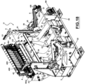
- said structure comprises a base platform (3) with two sides (30) between which a first motorized belt (31) is positioned, arranged along a corresponding first closed path around a plurality of guide rollers (32, 33, 34), one of which (33) is controlled by an electric motor (3M).
- a guide roller (34) is mounted transversely on two front arms (37) of the platform (3), which arms (37) are hinged with horizontal axis "H" each to a respective side (30) and are connected to an actuator (not visible in the drawings) which allows said arms to be rotated around said axis (H) as the diameter of the first parent reel (1) present in the first position (P1) decreases.
- the arms (37) are belt-tightening arms for the first motorized belt (31) and are progressively rotated towards the first position (P1) as the diameter of the first reel (1) decreases.
- a blade (B) In a position in front of the guide roller (34) there is a blade (B), the function of which is described below, which extends transversely between said arms (37).
- the motorized belt (31) has an upper section (310), a lower section (311) and lateral sections which close the circuit followed by the motorized belt itself, whose direction of movement is indicated by the arrows " C" in the attached drawings.
- the motorized belt (31) acts as a driving member for the parent reel (1) in its operating position (P1), that is, in the position normally occupied by the parent reel (1) until it is exhausted.
- the motorized belt (31) can be doubled, in the sense that it can be realized as a double belt composed of two belts placed side by side as shown in Figs. 18-19 .
- the reference “N1" indicates the paper web which unwinds from the parent reel (1) and the arrows "F1" indicate the direction followed by the paper web (N1).
- the operating position (P1) is defined by a support (35) formed on an upper side of the platform (3).
- the support (35), arranged on both sides (30) of the platform (3), is preferably a concave support, with the concavity turned upwards, to receive the pins (10) normally inserted in the central core of the reel (1), from which the same pins project axially both to be engaged by the bridge crane (CP) described below, and to allow the reel (1) to rotate around its own axis when it is placed on the support (35).
- a lever (36) for locking/unlocking the respective pin (10) is associated with the support (35).
- the lever (36) defines, in cooperation with the concavity of the support (35), a seat with a substantially circular cross-section in which the pin (10) is free to rotate but cannot translate, said seat being open or closed according to the position of the lever (36): when the seat of the pin (10) is open, a parent reel can be positioned on the support (35) and can be removed from the support itself, while when said seat is closed, a parent reel positioned on the support (35) is locked in the operating position (P1) but is free to rotate around its own axis, that is, around the axis of the pins (10).
- an arm (4) which supports a second motorized belt (41) arranged along a second path closed around a plurality of guide rollers (42, 43), one of which (43) is motorized.
- the reference “M43" in Fig. 18 and Fig.19 indicates an electric motor that drives the roller (43).
- the arm (4) is linked to the front appendix (A3) of the platform (3) by means of a hinge with axis (X) perpendicular to the appendix (A3) itself.
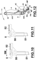
- the arm (4) with the second motorized belt (41) supported by this arm, can be made to rotate around the said axis (X) by means of a respective actuator (M4) from and towards the area above the operating position (P1) of the parent reel (1) as schematically shown by the arrow "K" in Fig.12 .
- the arm (4) can be made to rotate by a motorized pinion (4P) meshing with an arcuated rack (4C) applied on the arm (4).
- the arm (4) also supports a third motorized belt (44) closed in a ring on a motorized roller (43) of the second belt (41), from which its motion derives, and on further guide rollers (45).
- the third motorized belt (44) constitutes an extension of the second belt (41) which reaches the nip (PN) of a ply-bonding unit.
- the latter is formed by a plurality of a ply-bonding wheels (M1) and a counter-roller (M2) oriented transversely with respect to the direction (F1) followed by the web (N1) which unwinds from the parent reel (1) placed in the operating position (P1).
- the ply-bonding unit is designed to mechanically join the paper webs (N1, N2) which unwind from the first and second parent reels in a step of replacing the first parent reel with the second parent reels further described below.
- the reference “410” denotes the internal side of the second motorized belt, that is, the side of the latter facing the inside of the unwinder (U), while the reference “440” denotes the internal side of the third motorized belt, i.e. the side of the latter facing the nip (PN) of the ply-bonding unit.
- the ply-bonding wheels have a knurled surface or are in any way machined so as to exhibit reliefs in correspondence with predetermined parts of their surface and, in known ways, in cooperation with the counter-roller (M2) they determine the mechanical joining of two paper webs which transit simultaneously through the nip (PN) while the ply-bonding wheels are pushed towards the counter-roller.
- the ply-bonding wheels (M1) are normally spaced from the counter-roller (M2) by elastic members arranged in the ply-bonding unit and are pushed towards the counter-roller (M2) by a pneumatic actuator (MP) for obtaining the ply-bonding of the webs that pass through the nip (PN).
- MP pneumatic actuator
- the ply-bonding unit described above constitutes an example of realization of a zone for joining the paper webs (N1, N2) unwound from the parent reels (1, 2), arranged in correspondence with an exit (H) of the webs (N1, N2) from the unwinder.
- the second and third motorized belts constitute a guiding surface (41, 44) which guides the second paper web towards said joining zone.
- an idle or motorized roller is arranged immediately upstream of the nip (PN), oriented parallel to the nip itself, which supports the web (N1) unwound from the first parent reel (1).
- a second position (P2) is formed in which a second parent reel (2) can be placed, intended to replace the first parent reel (1) which is in the operating position (P1) when the diameter of the first parent reel reaches a predetermined minimum value.
- transfer means are arranged and acting, for transferring the second parent reel (2) from the second position (P2) to the first position (P1).
- said transfer means comprise two concave supports (5) with the concavity facing upwards, each of which is arranged on a carriage (50) which can be moved along a respective guide column (51) placed next to a corresponding side (30) of the platform (3).
- the carriages (50) are moved along the columns (51) by respective ball screws or driving screws operated by an electric motor (not visible in the drawings).
- the supports (5) are mounted horizontally sliding on an upper side of the respective carriages (50).
- the horizontal movement (5M) of the supports (5) is controlled by corresponding actuators (51) also arranged on the upper side of the supports (5).
- the supports (5) are in the extracted position, as in Fig.
- the first position (P1) is in correspondence with the front side of a guide (6) on which a carriage (60) is mounted which can be moved along the same guide (6) by means of a chain (6B) controlled by a corresponding actuator (6M), as indicated by the double arrow "F6".
- the guide (6) is formed by two plates (61) each placed on the side of a respective side (30) of the platform (3).
- the plates (61) have a front side, in correspondence of said first position (P1), and a rear side in correspondence of said third position (P3).
- this rotation mechanism of the guide (6) comprises two pneumatic actuators (6A), each placed on a respective side (30) and each of which activates a cam (6C) intended to interact with a roller (6D) mounted on a corresponding side of the plate (61).
- the arrow "F6” indicates the clockwise rotation of the guide (6) around the axis (K), while the arrow “G6” indicates the stroke of the carriage (60) towards the front side of the same guide.
- the arrow “H6” indicates the anticlockwise rotation of the guide (6) while the arrow (L6) represents the stroke of the carriage (60) towards the rear side of the guide itself.
- the actuators (6A) control the rotation of the plates (61), i.e. of the guide (6), around the axis (K), while the belts (6B) control the stroke of the carriage (60) along the same guide.
- the carriage (60) is formed by two plates, each of which is constrained to a respective chain (6B) of the guide (6).
- Each of the plates forming the carriage (60) is provided with sliding pads (not visible in the drawings) able to slide in a rectilinear guide (6E) arranged on a respective plate (61) of the guide (6).
- a concave seat (63) is formed on the upper side of the plates (62), with the concavity facing upwards, for receiving a pin of a parent reel arranged in the operating unwinding position (P1).
- the carriage (60) therefore allows to engage the parent reel present in position (P1) and transport it to the rear side (P3) of the guide (6) when the parent reel present in position (P1) must be replaced with the one set in the waiting position (P2).
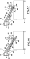
- said guide (6) is inclined, with the front side lower than the rear side, in such a way that its rear side is more raised, facilitating the gripping of the exhausted parent reel (1) by the bridge crane (CP ) in position (P3).
- the supports (35) are the outermost elements and the levers (36) are each arranged next to the respective support (35), on the inside of the latter (side facing the double belt 31).
- the plates (61) of the guide (6) are mounted on the external sides of the sides (30), i.e. on the side of these facing the respective levers (36).
- the plates forming the carriage (60) and the belts (6B) are mounted on the internal side of the plates (61), i.e. on the side of these facing the double belt (31).
- the carriages (50) consist of plates mounted on guides (52) formed on the internal side of the columns (51), i.e. on the side of these facing the double belt (31).
- Each carriage (50) moves, on the respective column (51), in a space comprised between a respective plate of the carriage (60) and the corresponding arm (37).
- the latter is more internal, i.e. closer to the central part of the unwinder, part which is occupied by the double belt (31). Therefore, starting from the outside of the unwinder and proceeding inwards, in correspondence with the position (P1) there are, for each side of the unwinder: the support (35), the lever (36), the plate (61) of the guide (6), the carriage plate (60) and the arm (37); and the space between the plate of the trolley (60) and the arm (37) is crossed by the carriage (50).
- the unwinder (U) comprises pneumatic means adapted to approach the web (N2) of the reel arranged in the waiting position (P2) to the inner side (410) of the second motorized belt (41).
- said pneumatic means can consist of nozzles (7) fed with compressed air, arranged on the platform (3) and oriented towards the second motorized belt (41).
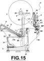
- said pneumatic means can consist of a suction box (8) arranged on the rear side of the second motorized belt (41), i.e.
- Fig. 15 differs from that illustrated in Figs. 1-8 only in the different embodiment of the pneumatic means which determine the adhesion of the web (N2) to the guiding surface (41, 44).
- the free edge of the web (N2) can be pneumatically made to adhere to the second motorized belt (41) in the exchange phase of the parent reels (1, 2), i.e. when the reel set in position (P2) must replace the reel present in position (P1).
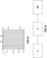
- the second motorized belt (41) consists of a plurality of side-by-side belts (400) of reduced width with respect to the length of the reels (1, 2), i.e. of reduced width with respect to the width of the paper webs (N1, N2 ), spaced along the guide rollers (42, 43) so as to leave a free space (401) between one belt (400) and the other, as schematically represented in Fig. 13 .
- the free space (401) between the belts (400) favors the action of the pneumatic means used to obtain the adhesion of the web (2) to the guiding surface (41, 44).
- the third motorized belt (44) can also be realized as a plurality of side-by-side belts of reduced width with respect to the width of the belts (N1, N2) similarly to what has been said for the second motorized belt (41).
- the second motorized belt (41) and the third motorized belt (44) constitute an example of embodiment of a guiding surface for the web (N2) in the phase of insertion of the latter in the joining area of the webs (N1 , N2) which, in the example described above, consists of the ply-bonding unit (M1, M2).
- the pneumatic means (7, 8) assist the action of the guiding surface (41, 44) allowing the web (N2) to adhere to the same surface when the reel set in position (P2) has to replace the present reel in position (P1).
- a possible exchange cycle of the parent reels (1, 2) in an unwinder according to the present invention is as follows.
- a parent reel (1) While a parent reel (1) is in the unwinding operating position (P1) and feeds the respective web material (N1) to the machines that use it, another parent reel (2) is led to the above waiting position (P2) by the bridge crane (CP) which deposits the respective pins (20) on the supports (5) arranged in this position by the carriage (50) and subsequently releases the pins (20) and moves away from the unwinder.
- the parent reel (2) is oriented in such a way as to present the free edge (L2) of the respective web (N2) facing forward, so that this edge is in front of the second motorized belt (41) when the bridge crane positions the new parent reel (2) on the supports (5).
- the rotation of the parent reel (1) is determined by the first motorized belt (31).
- the rotation speed of the same is reduced, with a consequent reduction in the feeding speed of the respective web and, with known methods, the speed of the machines using that web is also reduced.
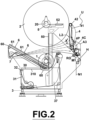
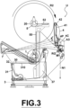
- the supply of compressed air from the nozzles (7) is activated as schematically illustrated in Fig. 2 and Fig. 3 where the dotted lines represent the flow of air exiting the nozzles (7) and directed towards the second motorized belt (41).
- the second motorized belt (41) is activated and the arm (4) is rotated to bring the second motorized belt (41) into contact with the parent reel (2) arranged on the supports (5) in the waiting position (P2) .
- the reel (2) present on the supports (5) is rotated, as indicated by the arrow "R2" in Fig. 3 , and, due to the thrust exerted from the air supplied by the nozzles (7) or from the suction exerted by the suction box (8), the free edge (L2) of the belt (N2) adheres to the second motorized belt which guides it towards the third motorized belt (44) and the ply-bonding unit (M1, M2).
- the web (N1) which unwinds from the reel (1) in the run-out phase continues to cross the space between the ply-bonding wheels and the counter-roller (M1, M2) and the carriage (60) is brought to the position (P1).
- the ply-bonding wheels and the counter-roller (M1, M2) are brought against each other, so as to join the webs (N1, N2) unwound simultaneously from the reels (1, 2), after which the web (N1) of the reel (1) is cut.
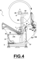
- the blade (B) which intervenes on the web (N1) to cut it in this phase is arranged in a predetermined position along the path of the web (N1) upstream of the ply-bonding unit (M1, M2), as schematically shown in Fig.4 where the references "T1" and "L1" represent the tail of the paper web (N1) directed towards the ply-bonding unit and respectively the edge of the paper web which remains on the exhausted reel (1).
- the blade (B) is advantageously mounted on the arms (37) because, in this way, its position varies with the rotation of these arms and, therefore, varies with the diameter of the first reel (1).
- the paper web that comes out from the ply-bonding unit (M1, M2) is identified by both references “N1" and "N2" because in this phase both the webs come out from the unwinder.
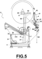
- After joining the webs (N1, N2) and cutting the web (N1), from the unwinder comes out only the web (N2) of the reel (2) that has not yet been placed in the operating unwinding position (P1), as schematically represented in Fig. 5 .
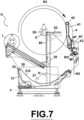
- the carriage (60) which has been brought under the exhausted reel (1), engages the latter and transports it to the third position (P3) along the guide (6) by performing the movements (F6, G6, H6, L6) previously described, and the arms (37) are rotated to distance them from the first position (P1), as shown in Fig.6 and Fig.7 .
- the carriage (50) transports the reel (2) on the supports (35) in the operative position (P1), as shown in Fig.8 (in which for graphic simplification the carriage 50 and the columns 51 are not shown).
- the first motorized belt (31) determines its rotation, after which the arm (4) is returned to its initial position.
- the ply-bonding wheels (M1) once their function is no longer required, have been returned to their starting configuration spaced from the counter-roller (M2).
- the exhausted parent reel is picked up by the bridge crane (CP) and transported out of the unwinder. The process described above is repeated cyclically. The replacement of the exhausted parent reel (1) with the parent reel (2) which takes its place takes place without interrupting the feeding of paper to the machines that use it.
- the machines that use the material (N1; N2) coming out of the unwinder (U) are an embosser (E) and a rewinder (RW) that receives the material (N1, N2) processed by the embosser (E) and uses it to produce logs of paper material from which rolls of toilet paper are obtained according to a plant and functional configuration known per se.
- the adhesion of the web (N2) to the second motorized belt (41) is determined by the suction operated through the suction box.
- an unwinder and a method according to the present invention are equally applicable to the case of non-paper web materials, such as for example non-woven webs. From the foregoing description it is evident that an unwinder according to the present invention allows to implement a method for unwinding web materials (N1, N2) from two corresponding parent reels (1, 2), wherein a first parent reel (1) in a depletion phase is replaced by a second parent reel (2) which takes the place of the first parent reel at the end of the replacement, wherein during said replacement a first and a second web material (N1, N2) is unwound from both parent reels, wherein before the completion of said replacement the first web material (N1) is joined to the second web material (N2) and then it is cut, wherein the joining of said web-like materials (N1, N2) is preceded by a step of inserting the second web material (N2) in an area where the two web materials (N1, N2) are joined, wherein during the step of inserting the second web material (N2) in said joining area the second web
- the second parent reel (2) before carrying out said replacement, can be placed in a temporary waiting and unwinding position (P2) above another position (P1) occupied by the first reel (1). Furthermore, in accordance with the embodiment described above, the first reel (1) is rotated by a motorized belt (31) acting by contact on the first reel in the position (P1) occupied by the latter.
- the guiding surface (41, 44) can be constituted by motorized belts which, while guiding the second web (N2) towards the said joining area, determine the rotation of the second reel (2) around its own axis.
- the adhesion of the second web (N2) to the guiding surface (41, 44) can be carried out by means of compressed air supplied by nozzles (7) oriented towards this surface or by suction operated through the guiding surface itself by means of a suction box (8).
- the unwinder described above is an unwinder comprising:
- said guide surface (41, 44) is a movable surface supported by an arm (4) controlled to arrange the same guide surface (41, 44) in contact with the reel (2) present in the waiting position (P2) to drag it into rotation around its axis.
- said positions (P1, P2, P3) are formed by concave supports with the concavity facing upwards
- a support (5) is formed on a carriage (50) which can be moved alternatively between the waiting position (P2) and the operating position (P1)
- a support is formed on another carriage (60) which can be moved alternately between the removal position (P3) and the operating position (P1).
- said pneumatic means are formed by nozzles (7) fed with compressed air and oriented towards said guide surface (41, 44) or by a suction box (8) placed on a rear side of the guide surface (41, 44).
- said means for joining the web-like materials comprise a ply-bonding unit (M1, M2).
- the unwinder comprises cutting means suitable for cutting the web unwound from the reel (1) which occupies the operating position (P1).
Landscapes
- Replacement Of Web Rolls (AREA)
Claims (13)
- Verfahren zum Abwickeln von Bahnmaterialien (N1, N2) von zwei entsprechenden Mutterrollen (1, 2), wobei eine erste Mutterrolle (1) in einer Erschöpfungsphase durch eine zweite Mutterrolle (2) ersetzt wird, die den Platz der ersten Mutterrolle an dem Ende der Ersetzung einnimmt, wobei während der Ersetzung ein erstes und ein zweites Bahnmaterial (N1, N2) von beiden Mutterrollen abgewickelt werden, dadurch gekennzeichnet, dassvor dem Abschluss der Ersetzung das erste Bahnmaterial (N1) mit dem zweiten Bahnmaterial (N2) verbunden wird und es dann geschnitten wird, dem Verbinden der Bahnmaterialien (N1, N2) ein Schritt des Einführens des zweiten Bahnmaterials (N2) in einem Bereich, in dem die zwei Bahnmaterialien (N1, N2) verbunden sind, vorausgeht undwährend des Schrittes des Einführens des zweiten Bahnmaterials (N2) in dem Verbindungsbereich das zweite Bahnmaterial (N2) auf einer Führungsfläche (41, 44) geführt wird, die es zu dem Verbindungsbereich führt, undin dem Einführungsschritt das zweite Bahnmaterial (N2) pneumatisch an der Führungsfläche haftet.
- Verfahren nach Anspruch 1, dadurch gekennzeichnet, dass vor dem Durchführen der Ersetzung die zweite Mutterrolle (2) in einer Warte- und temporären Abwickelposition (P2) über einer anderen Position (P1), die durch die erste Mutterrolle (1) eingenommen wird, platziert ist.
- Verfahren nach Anspruch 1, dadurch gekennzeichnet, dass die erste Mutterrolle (1) durch einen motorisierten Riemen (31) gedreht wird, der durch Kontakt auf sie einwirkt, in einer Position (P1), die durch die letztere eingenommen wird.
- Verfahren nach Anspruch 1, dadurch gekennzeichnet, dass die Führungsfläche (41, 44) aus motorisierten Riemen besteht, die, während das zweite Bahnmaterial (N2) zu dem Verbindungsbereich geführt wird, die Drehung der zweiten Mutterrolle (2) um eine jeweilige Drehachse bewirken.
- Verfahren nach Anspruch 1, dadurch gekennzeichnet, dass die Haftung des zweiten Bahnmaterials (N2) an der Führungsfläche (41, 44) mittels Druckluft, die durch Düsen (7) zugeführt wird, die zu der Fläche ausgerichtet sind, oder durch Sog, der durch die Führungsfläche selbst mittels eines Sogkastens (8) betrieben wird, durchgeführt wird.
- Verfahren nach einem der vorhergehenden Ansprüche, dadurch gekennzeichnet, dass die bahnartigen Materialien aus Papier hergestellt sind.
- Verfahren nach einem der vorhergehenden Ansprüche, dadurch gekennzeichnet, dass die bahnartigen Materialien Vliesstoffbahnen sind.
- Abwickelvorrichtung, dadurch gekennzeichnet, dass sie zum Abwickeln von Bahnmaterialien (N1, N2) von jeweiligen Mutterrollen (1, 2) nach einem der vorhergehenden Ansprüche konfiguriert ist, wobei die Abwickelvorrichtung Folgendes umfasst:- eine Struktur, auf der Stützelemente, die ausgelegt sind, um eine erste Mutterrolle (1) und eine zweite Mutterrolle (2) in verschiedenen Positionen zu stützen, gebildet sind, wobei die Stützelemente konfiguriert sind, um die Mutterrollen (1, 2) während Drehung derselben um jeweilige Längsachsen zu stützen;- motorisierte Schleppmittel, die konfiguriert sind, um die Drehung der Mutterrollen (1, 2) mit einer vorbestimmten Winkelgeschwindigkeit um die jeweiligen Längsachsen zu steuern;- Verbindungsmittel um die Bahnmaterialien (N1, N2), die von den Mutterrollen (1, 2) abgewickelt werden, miteinander zu verbinden, wenn eine davon in einer Phase der Erschöpfung durch die andere ersetzt werden muss;
Mittel zum Überführen einer Mutterrolle von einer Warteposition (P2) in eine Betriebsposition (P1), wenn der Durchmesser einer Mutterrolle, die in der Betriebsposition (P1) angeordnet ist, einen vorbestimmten Mindestwert erreicht;- Mittel zum Überführen einer Mutterrolle von der Betriebsposition (P1) in eine Entnahmeposition (P3), wenn die andere Mutterrolle von der Warteposition (P2) in die Betriebsposition (P1) überführt wird;- eine Führungsfläche (41, 44), die konfiguriert ist, um die Bahn (N2), die von der Rolle (2) der Warteposition (P2) abgewickelt wird, zu den Verbindungsmitteln zu führen; und- pneumatische Mittel (7; 8), die aktiviert werden können, um auf dem Bahnmaterial (N2), das von der Rolle (2) der Warteposition (P2) abgewickelt wird, einen Druck oder Sog zu produzieren, der zu der Führungsfläche (41, 44) gerichtet ist, während letztere es zu den Verbindungsmitteln führt. - Abwickelvorrichtung nach Anspruch 8, dadurch gekennzeichnet, dass die Führungsfläche (41, 44) eine bewegbare Fläche ist, die durch einen Arm (4) gestützt wird, der gesteuert wird, um die gleiche Führungsfläche (41, 44) in Kontakt mit der Rolle (2) der Warteposition (P2) anzuordnen, um sie in Drehung um ihre eigene Achse zu ziehen.
- Abwickelvorrichtung nach Anspruch 8, dadurch gekennzeichnet, dass die Positionen (P1, P2, P3) durch konkave Stützen mit der nach oben gerichteten Konkavität gebildet sind, eine Stütze (5) an einem Schlitten (50) gebildet ist, der abwechselnd zwischen der Warteposition (P2) und der Betriebsposition (P1) bewegt werden kann, und eine Stütze an einem anderen Schlitten (60) gebildet ist, der abwechselnd zwischen der Entnahmeposition (P3) und der Betriebsposition (P1) bewegt werden kann.
- Abwickelvorrichtung nach Anspruch 8, dadurch gekennzeichnet, dass die pneumatischen Mittel durch Düsen (7), die mit Druckluft versorgt werden und zu der Führungsfläche (41, 44) ausgerichtet sind, oder durch einen Sogkasten (8), der an einer Rückseite der Führungsfläche (41, 44) platziert ist, gebildet sind.
- Abwickelvorrichtung nach Anspruch 8, dadurch gekennzeichnet, dass die Mittel zum Verbinden der bahnartigen Materialien eine Lagenbindungseinheit (M1, M2) umfassen.
- Abwickelvorrichtung nach Anspruch 8, dadurch gekennzeichnet, dass sie Schneidmittel umfasst, die zum Schneiden des Bahnmaterials, das von der Rolle (1), welche die Betriebsposition (P1) einnimmt, abgewickelt wird, geeignet sind.
Priority Applications (1)
| Application Number | Priority Date | Filing Date | Title |
|---|---|---|---|
| RS20250589A RS66945B1 (sr) | 2021-06-15 | 2022-06-11 | Odmotavač i radni postupak za odmotavanje trakastih materijala sa matičnih koturova |
Applications Claiming Priority (2)
| Application Number | Priority Date | Filing Date | Title |
|---|---|---|---|
| IT102021000015542A IT202100015542A1 (it) | 2021-06-15 | 2021-06-15 | Svolgitore e metodo operativo per svolgere materiali nastriformi da bobine madri. |
| PCT/IT2022/050167 WO2022264180A1 (en) | 2021-06-15 | 2022-06-11 | Unwinder and operating method for unwinding web materials from parent reels |
Publications (2)
| Publication Number | Publication Date |
|---|---|
| EP4355673A1 EP4355673A1 (de) | 2024-04-24 |
| EP4355673B1 true EP4355673B1 (de) | 2025-04-30 |
Family
ID=77627388
Family Applications (1)
| Application Number | Title | Priority Date | Filing Date |
|---|---|---|---|
| EP22735632.6A Active EP4355673B1 (de) | 2021-06-15 | 2022-06-11 | Abwickelvorrichtung und betriebsverfahren zum abwickeln von bahnmaterialien von mutterrollen |
Country Status (9)
| Country | Link |
|---|---|
| US (1) | US20240199361A1 (de) |
| EP (1) | EP4355673B1 (de) |
| BR (1) | BR112023019804A2 (de) |
| ES (1) | ES3033209T3 (de) |
| FI (1) | FI4355673T3 (de) |
| IT (1) | IT202100015542A1 (de) |
| PL (1) | PL4355673T3 (de) |
| RS (1) | RS66945B1 (de) |
| WO (1) | WO2022264180A1 (de) |
Families Citing this family (1)
| Publication number | Priority date | Publication date | Assignee | Title |
|---|---|---|---|---|
| US20240317525A1 (en) * | 2023-03-24 | 2024-09-26 | New Era Converting Machinery, Inc. | Dual position automatic winder |
Family Cites Families (4)
| Publication number | Priority date | Publication date | Assignee | Title |
|---|---|---|---|---|
| US5906333A (en) * | 1997-04-16 | 1999-05-25 | Paper Converting Machine Company | Center drive unwind system |
| ITFI20030065A1 (it) * | 2003-03-13 | 2004-09-14 | Perini Fabio Spa | Dispositivo svolgitore per bobine di materiale nastriforme con organi di accumulo temporaneo del materiale svolto nella fase di cambio bobina e relativo metodo |
| ITFI20050010A1 (it) * | 2005-01-18 | 2006-07-19 | O M Futura S P A | Metodo e dispositivo per l'esecuzione automatica del cambio bobina in uno svolgitore |
| ITFI20110253A1 (it) * | 2011-11-23 | 2013-05-24 | Perini Fabio Spa | "svolgitore per bobine e metodo di svolgimento" |
-
2021
- 2021-06-15 IT IT102021000015542A patent/IT202100015542A1/it unknown
-
2022
- 2022-06-11 FI FIEP22735632.6T patent/FI4355673T3/fi active
- 2022-06-11 US US18/287,007 patent/US20240199361A1/en active Pending
- 2022-06-11 BR BR112023019804A patent/BR112023019804A2/pt unknown
- 2022-06-11 RS RS20250589A patent/RS66945B1/sr unknown
- 2022-06-11 ES ES22735632T patent/ES3033209T3/es active Active
- 2022-06-11 WO PCT/IT2022/050167 patent/WO2022264180A1/en not_active Ceased
- 2022-06-11 EP EP22735632.6A patent/EP4355673B1/de active Active
- 2022-06-11 PL PL22735632.6T patent/PL4355673T3/pl unknown
Also Published As
| Publication number | Publication date |
|---|---|
| IT202100015542A1 (it) | 2022-12-15 |
| EP4355673A1 (de) | 2024-04-24 |
| FI4355673T3 (fi) | 2025-06-18 |
| PL4355673T3 (pl) | 2025-08-04 |
| ES3033209T3 (en) | 2025-07-31 |
| RS66945B1 (sr) | 2025-07-31 |
| WO2022264180A1 (en) | 2022-12-22 |
| US20240199361A1 (en) | 2024-06-20 |
| BR112023019804A2 (pt) | 2024-01-16 |
Similar Documents
| Publication | Publication Date | Title |
|---|---|---|
| RU2605344C2 (ru) | Разматыватель для рулона и способ размотки | |
| EP2142456B1 (de) | Vorrichtung und verfahren zum brechen einer bahn | |
| JP5933564B2 (ja) | ウェブ材料のロールを製造する巻取り機及び方法 | |
| US7909282B2 (en) | Center/surface rewinder and winder | |
| EP2797825B1 (de) | Abwickler von rollen mit bahnförmigem material | |
| EP3243777B1 (de) | Maschine und verfahren zum aufwickeln von bahnmaterialstreifen mit mitteln zum querschneiden der streifen und zum verankern der streifen am wickelkern | |
| JPS6259024B2 (de) | ||
| ITMI20012274A1 (it) | Ribobunatrice automatica particolarmente per film flessibile di materiale plastico e relativo metodo di produzione di rotoli | |
| EP4355673B1 (de) | Abwickelvorrichtung und betriebsverfahren zum abwickeln von bahnmaterialien von mutterrollen | |
| ITPI20080058A1 (it) | Apparato, e relativo metodo, per la trasformazione di nastri adiacenti di materiale flessibile. | |
| AU2008243899B2 (en) | Apparatus and method for breaking a web | |
| ITMI992293A1 (it) | Dispositivo di introduzione di un'anima di avvolgimento in una macchina ribobinatrice | |
| IT201900003205A1 (it) | Un dispositivo per la sostituzione di bobine in uno svolgitore e relativo metodo | |
| JPH0539150A (ja) | ウエブ巻取機および方法 | |
| EP2758328A2 (de) | Gleichzeitigesaufwickeln von gewebebahnen |
Legal Events
| Date | Code | Title | Description |
|---|---|---|---|
| STAA | Information on the status of an ep patent application or granted ep patent |
Free format text: STATUS: UNKNOWN |
|
| STAA | Information on the status of an ep patent application or granted ep patent |
Free format text: STATUS: THE INTERNATIONAL PUBLICATION HAS BEEN MADE |
|
| PUAI | Public reference made under article 153(3) epc to a published international application that has entered the european phase |
Free format text: ORIGINAL CODE: 0009012 |
|
| STAA | Information on the status of an ep patent application or granted ep patent |
Free format text: STATUS: REQUEST FOR EXAMINATION WAS MADE |
|
| 17P | Request for examination filed |
Effective date: 20230921 |
|
| AK | Designated contracting states |
Kind code of ref document: A1 Designated state(s): AL AT BE BG CH CY CZ DE DK EE ES FI FR GB GR HR HU IE IS IT LI LT LU LV MC MK MT NL NO PL PT RO RS SE SI SK SM TR |
|
| DAV | Request for validation of the european patent (deleted) | ||
| DAX | Request for extension of the european patent (deleted) | ||
| GRAP | Despatch of communication of intention to grant a patent |
Free format text: ORIGINAL CODE: EPIDOSNIGR1 |
|
| STAA | Information on the status of an ep patent application or granted ep patent |
Free format text: STATUS: GRANT OF PATENT IS INTENDED |
|
| GRAS | Grant fee paid |
Free format text: ORIGINAL CODE: EPIDOSNIGR3 |
|
| INTG | Intention to grant announced |
Effective date: 20250221 |
|
| GRAA | (expected) grant |
Free format text: ORIGINAL CODE: 0009210 |
|
| STAA | Information on the status of an ep patent application or granted ep patent |
Free format text: STATUS: THE PATENT HAS BEEN GRANTED |
|
| AK | Designated contracting states |
Kind code of ref document: B1 Designated state(s): AL AT BE BG CH CY CZ DE DK EE ES FI FR GB GR HR HU IE IS IT LI LT LU LV MC MK MT NL NO PL PT RO RS SE SI SK SM TR |
|
| REG | Reference to a national code |
Ref country code: CH Ref legal event code: EP Ref country code: GB Ref legal event code: FG4D |
|
| REG | Reference to a national code |
Ref country code: IE Ref legal event code: FG4D |
|
| REG | Reference to a national code |
Ref country code: DE Ref legal event code: R096 Ref document number: 602022013955 Country of ref document: DE |
|
| REG | Reference to a national code |
Ref country code: FI Ref legal event code: FGE |
|
| REG | Reference to a national code |
Ref country code: SE Ref legal event code: TRGR |
|
| PGFP | Annual fee paid to national office [announced via postgrant information from national office to epo] |
Ref country code: FI Payment date: 20250627 Year of fee payment: 4 |
|
| PGFP | Annual fee paid to national office [announced via postgrant information from national office to epo] |
Ref country code: DE Payment date: 20250618 Year of fee payment: 4 |
|
| PGFP | Annual fee paid to national office [announced via postgrant information from national office to epo] |
Ref country code: RS Payment date: 20250612 Year of fee payment: 4 |
|
| PGFP | Annual fee paid to national office [announced via postgrant information from national office to epo] |
Ref country code: FR Payment date: 20250627 Year of fee payment: 4 |
|
| PGFP | Annual fee paid to national office [announced via postgrant information from national office to epo] |
Ref country code: AT Payment date: 20250721 Year of fee payment: 4 |
|
| PGFP | Annual fee paid to national office [announced via postgrant information from national office to epo] |
Ref country code: SE Payment date: 20250618 Year of fee payment: 4 |
|
| REG | Reference to a national code |
Ref country code: ES Ref legal event code: FG2A Ref document number: 3033209 Country of ref document: ES Kind code of ref document: T3 Effective date: 20250731 |
|
| REG | Reference to a national code |
Ref country code: NL Ref legal event code: MP Effective date: 20250430 |
|
| REG | Reference to a national code |
Ref country code: AT Ref legal event code: MK05 Ref document number: 1789896 Country of ref document: AT Kind code of ref document: T Effective date: 20250430 |
|
| PG25 | Lapsed in a contracting state [announced via postgrant information from national office to epo] |
Ref country code: PT Free format text: LAPSE BECAUSE OF FAILURE TO SUBMIT A TRANSLATION OF THE DESCRIPTION OR TO PAY THE FEE WITHIN THE PRESCRIBED TIME-LIMIT Effective date: 20250901 |
|
| PGFP | Annual fee paid to national office [announced via postgrant information from national office to epo] |
Ref country code: ES Payment date: 20250731 Year of fee payment: 4 |
|
| REG | Reference to a national code |
Ref country code: LT Ref legal event code: MG9D |
|
| PG25 | Lapsed in a contracting state [announced via postgrant information from national office to epo] |
Ref country code: NO Free format text: LAPSE BECAUSE OF FAILURE TO SUBMIT A TRANSLATION OF THE DESCRIPTION OR TO PAY THE FEE WITHIN THE PRESCRIBED TIME-LIMIT Effective date: 20250730 Ref country code: GR Free format text: LAPSE BECAUSE OF FAILURE TO SUBMIT A TRANSLATION OF THE DESCRIPTION OR TO PAY THE FEE WITHIN THE PRESCRIBED TIME-LIMIT Effective date: 20250731 |
|
| PG25 | Lapsed in a contracting state [announced via postgrant information from national office to epo] |
Ref country code: NL Free format text: LAPSE BECAUSE OF FAILURE TO SUBMIT A TRANSLATION OF THE DESCRIPTION OR TO PAY THE FEE WITHIN THE PRESCRIBED TIME-LIMIT Effective date: 20250430 |
|
| PGFP | Annual fee paid to national office [announced via postgrant information from national office to epo] |
Ref country code: TR Payment date: 20250721 Year of fee payment: 4 Ref country code: PL Payment date: 20250611 Year of fee payment: 4 Ref country code: IT Payment date: 20250630 Year of fee payment: 4 |
|
| PG25 | Lapsed in a contracting state [announced via postgrant information from national office to epo] |
Ref country code: BG Free format text: LAPSE BECAUSE OF FAILURE TO SUBMIT A TRANSLATION OF THE DESCRIPTION OR TO PAY THE FEE WITHIN THE PRESCRIBED TIME-LIMIT Effective date: 20250430 |
|
| PG25 | Lapsed in a contracting state [announced via postgrant information from national office to epo] |
Ref country code: AT Free format text: LAPSE BECAUSE OF FAILURE TO SUBMIT A TRANSLATION OF THE DESCRIPTION OR TO PAY THE FEE WITHIN THE PRESCRIBED TIME-LIMIT Effective date: 20250430 Ref country code: HR Free format text: LAPSE BECAUSE OF FAILURE TO SUBMIT A TRANSLATION OF THE DESCRIPTION OR TO PAY THE FEE WITHIN THE PRESCRIBED TIME-LIMIT Effective date: 20250430 |
|
| PGFP | Annual fee paid to national office [announced via postgrant information from national office to epo] |
Ref country code: RO Payment date: 20250722 Year of fee payment: 4 |
|
| PG25 | Lapsed in a contracting state [announced via postgrant information from national office to epo] |
Ref country code: IS Free format text: LAPSE BECAUSE OF FAILURE TO SUBMIT A TRANSLATION OF THE DESCRIPTION OR TO PAY THE FEE WITHIN THE PRESCRIBED TIME-LIMIT Effective date: 20250830 |
|
| PG25 | Lapsed in a contracting state [announced via postgrant information from national office to epo] |
Ref country code: LV Free format text: LAPSE BECAUSE OF FAILURE TO SUBMIT A TRANSLATION OF THE DESCRIPTION OR TO PAY THE FEE WITHIN THE PRESCRIBED TIME-LIMIT Effective date: 20250430 |