EP4354549A1 - Einkern-mehrschalen-lithiummangan-eisenphosphat-verbundmaterial und herstellungsverfahren dafür sowie sekundärbatterie - Google Patents
Einkern-mehrschalen-lithiummangan-eisenphosphat-verbundmaterial und herstellungsverfahren dafür sowie sekundärbatterie Download PDFInfo
- Publication number
- EP4354549A1 EP4354549A1 EP23754096.8A EP23754096A EP4354549A1 EP 4354549 A1 EP4354549 A1 EP 4354549A1 EP 23754096 A EP23754096 A EP 23754096A EP 4354549 A1 EP4354549 A1 EP 4354549A1
- Authority
- EP
- European Patent Office
- Prior art keywords
- iron phosphate
- lithium manganese
- manganese iron
- carbon
- particles
- Prior art date
- Legal status (The legal status is an assumption and is not a legal conclusion. Google has not performed a legal analysis and makes no representation as to the accuracy of the status listed.)
- Pending
Links
Images

Classifications
-
- H—ELECTRICITY
- H01—ELECTRIC ELEMENTS
- H01M—PROCESSES OR MEANS, e.g. BATTERIES, FOR THE DIRECT CONVERSION OF CHEMICAL ENERGY INTO ELECTRICAL ENERGY
- H01M4/00—Electrodes
- H01M4/02—Electrodes composed of, or comprising, active material
- H01M4/36—Selection of substances as active materials, active masses, active liquids
- H01M4/362—Composites
- H01M4/366—Composites as layered products
-
- C—CHEMISTRY; METALLURGY
- C01—INORGANIC CHEMISTRY
- C01B—NON-METALLIC ELEMENTS; COMPOUNDS THEREOF; METALLOIDS OR COMPOUNDS THEREOF NOT COVERED BY SUBCLASS C01C
- C01B25/00—Phosphorus; Compounds thereof
- C01B25/16—Oxyacids of phosphorus; Salts thereof
- C01B25/26—Phosphates
- C01B25/45—Phosphates containing plural metal, or metal and ammonium
-
- C—CHEMISTRY; METALLURGY
- C01—INORGANIC CHEMISTRY
- C01B—NON-METALLIC ELEMENTS; COMPOUNDS THEREOF; METALLOIDS OR COMPOUNDS THEREOF NOT COVERED BY SUBCLASS C01C
- C01B32/00—Carbon; Compounds thereof
- C01B32/15—Nano-sized carbon materials
-
- H—ELECTRICITY
- H01—ELECTRIC ELEMENTS
- H01M—PROCESSES OR MEANS, e.g. BATTERIES, FOR THE DIRECT CONVERSION OF CHEMICAL ENERGY INTO ELECTRICAL ENERGY
- H01M10/00—Secondary cells; Manufacture thereof
- H01M10/05—Accumulators with non-aqueous electrolyte
- H01M10/052—Li-accumulators
- H01M10/0525—Rocking-chair batteries, i.e. batteries with lithium insertion or intercalation in both electrodes; Lithium-ion batteries
-
- H—ELECTRICITY
- H01—ELECTRIC ELEMENTS
- H01M—PROCESSES OR MEANS, e.g. BATTERIES, FOR THE DIRECT CONVERSION OF CHEMICAL ENERGY INTO ELECTRICAL ENERGY
- H01M4/00—Electrodes
- H01M4/02—Electrodes composed of, or comprising, active material
- H01M4/13—Electrodes for accumulators with non-aqueous electrolyte, e.g. for lithium-accumulators; Processes of manufacture thereof
- H01M4/136—Electrodes based on inorganic compounds other than oxides or hydroxides, e.g. sulfides, selenides, tellurides, halogenides or LiCoFy
-
- H—ELECTRICITY
- H01—ELECTRIC ELEMENTS
- H01M—PROCESSES OR MEANS, e.g. BATTERIES, FOR THE DIRECT CONVERSION OF CHEMICAL ENERGY INTO ELECTRICAL ENERGY
- H01M4/00—Electrodes
- H01M4/02—Electrodes composed of, or comprising, active material
- H01M4/36—Selection of substances as active materials, active masses, active liquids
- H01M4/58—Selection of substances as active materials, active masses, active liquids of inorganic compounds other than oxides or hydroxides, e.g. sulfides, selenides, tellurides, halogenides or LiCoFy; of polyanionic structures, e.g. phosphates, silicates or borates
- H01M4/5825—Oxygenated metallic salts or polyanionic structures, e.g. borates, phosphates, silicates, olivines
-
- H—ELECTRICITY
- H01—ELECTRIC ELEMENTS
- H01M—PROCESSES OR MEANS, e.g. BATTERIES, FOR THE DIRECT CONVERSION OF CHEMICAL ENERGY INTO ELECTRICAL ENERGY
- H01M4/00—Electrodes
- H01M4/02—Electrodes composed of, or comprising, active material
- H01M4/36—Selection of substances as active materials, active masses, active liquids
- H01M4/58—Selection of substances as active materials, active masses, active liquids of inorganic compounds other than oxides or hydroxides, e.g. sulfides, selenides, tellurides, halogenides or LiCoFy; of polyanionic structures, e.g. phosphates, silicates or borates
- H01M4/583—Carbonaceous material, e.g. graphite-intercalation compounds or CFx
- H01M4/587—Carbonaceous material, e.g. graphite-intercalation compounds or CFx for inserting or intercalating light metals
-
- H—ELECTRICITY
- H01—ELECTRIC ELEMENTS
- H01M—PROCESSES OR MEANS, e.g. BATTERIES, FOR THE DIRECT CONVERSION OF CHEMICAL ENERGY INTO ELECTRICAL ENERGY
- H01M4/00—Electrodes
- H01M4/02—Electrodes composed of, or comprising, active material
- H01M4/62—Selection of inactive substances as ingredients for active masses, e.g. binders, fillers
- H01M4/624—Electric conductive fillers
- H01M4/625—Carbon or graphite
-
- B—PERFORMING OPERATIONS; TRANSPORTING
- B82—NANOTECHNOLOGY
- B82Y—SPECIFIC USES OR APPLICATIONS OF NANOSTRUCTURES; MEASUREMENT OR ANALYSIS OF NANOSTRUCTURES; MANUFACTURE OR TREATMENT OF NANOSTRUCTURES
- B82Y30/00—Nanotechnology for materials or surface science, e.g. nanocomposites
-
- C—CHEMISTRY; METALLURGY
- C01—INORGANIC CHEMISTRY
- C01B—NON-METALLIC ELEMENTS; COMPOUNDS THEREOF; METALLOIDS OR COMPOUNDS THEREOF NOT COVERED BY SUBCLASS C01C
- C01B32/00—Carbon; Compounds thereof
- C01B32/05—Preparation or purification of carbon not covered by groups C01B32/15, C01B32/20, C01B32/25, C01B32/30
-
- C—CHEMISTRY; METALLURGY
- C01—INORGANIC CHEMISTRY
- C01P—INDEXING SCHEME RELATING TO STRUCTURAL AND PHYSICAL ASPECTS OF SOLID INORGANIC COMPOUNDS
- C01P2004/00—Particle morphology
- C01P2004/60—Particles characterised by their size
- C01P2004/62—Submicrometer sized, i.e. from 0.1-1 micrometer
-
- C—CHEMISTRY; METALLURGY
- C01—INORGANIC CHEMISTRY
- C01P—INDEXING SCHEME RELATING TO STRUCTURAL AND PHYSICAL ASPECTS OF SOLID INORGANIC COMPOUNDS
- C01P2004/00—Particle morphology
- C01P2004/60—Particles characterised by their size
- C01P2004/64—Nanometer sized, i.e. from 1-100 nanometer
-
- C—CHEMISTRY; METALLURGY
- C01—INORGANIC CHEMISTRY
- C01P—INDEXING SCHEME RELATING TO STRUCTURAL AND PHYSICAL ASPECTS OF SOLID INORGANIC COMPOUNDS
- C01P2004/00—Particle morphology
- C01P2004/80—Particles consisting of a mixture of two or more inorganic phases
-
- C—CHEMISTRY; METALLURGY
- C01—INORGANIC CHEMISTRY
- C01P—INDEXING SCHEME RELATING TO STRUCTURAL AND PHYSICAL ASPECTS OF SOLID INORGANIC COMPOUNDS
- C01P2006/00—Physical properties of inorganic compounds
- C01P2006/40—Electric properties
-
- H—ELECTRICITY
- H01—ELECTRIC ELEMENTS
- H01M—PROCESSES OR MEANS, e.g. BATTERIES, FOR THE DIRECT CONVERSION OF CHEMICAL ENERGY INTO ELECTRICAL ENERGY
- H01M4/00—Electrodes
- H01M4/02—Electrodes composed of, or comprising, active material
- H01M2004/021—Physical characteristics, e.g. porosity, surface area
-
- H—ELECTRICITY
- H01—ELECTRIC ELEMENTS
- H01M—PROCESSES OR MEANS, e.g. BATTERIES, FOR THE DIRECT CONVERSION OF CHEMICAL ENERGY INTO ELECTRICAL ENERGY
- H01M4/00—Electrodes
- H01M4/02—Electrodes composed of, or comprising, active material
- H01M2004/026—Electrodes composed of, or comprising, active material characterised by the polarity
- H01M2004/028—Positive electrodes
-
- Y—GENERAL TAGGING OF NEW TECHNOLOGICAL DEVELOPMENTS; GENERAL TAGGING OF CROSS-SECTIONAL TECHNOLOGIES SPANNING OVER SEVERAL SECTIONS OF THE IPC; TECHNICAL SUBJECTS COVERED BY FORMER USPC CROSS-REFERENCE ART COLLECTIONS [XRACs] AND DIGESTS
- Y02—TECHNOLOGIES OR APPLICATIONS FOR MITIGATION OR ADAPTATION AGAINST CLIMATE CHANGE
- Y02E—REDUCTION OF GREENHOUSE GAS [GHG] EMISSIONS, RELATED TO ENERGY GENERATION, TRANSMISSION OR DISTRIBUTION
- Y02E60/00—Enabling technologies; Technologies with a potential or indirect contribution to GHG emissions mitigation
- Y02E60/10—Energy storage using batteries
Definitions
- the present application relates to the technical field of battery materials, and more particularly to a single-core multi-shell lithium manganese iron phosphate cathode material and a preparation method thereof, and a secondary battery.
- a lithium-ion battery is advantageous in, for example, high operating voltage, low self-discharge, and good safety.
- the lithium-ion battery is mainly composed of a cathode material, an anode material, an electrolyte, a separator, and a casing.
- the cathode material mainly includes: lithium cobalt oxide, lithium manganese oxide, a nickel-manganese binary system, a nickel-cobalt-manganese ternary system, and a nickel-cobalt-aluminum ternary system, lithium iron phosphate, lithium manganese iron phosphate, and the like.
- lithium iron phosphate (LiFePO 4 ) is advantageous of low cost, high safety, and good cycle life.
- Lithium manganese iron phosphate (LMFP, LiMn 1-x FexPO 4 ) is developed on the basis of lithium iron phosphate modification, and is a solid solution material composed of lithium iron phosphate and lithium manganese phosphate, thus having similar properties to lithium iron phosphate and lithium manganese phosphate, as well as having good thermal and chemical stability. Compared with lithium iron phosphate, lithium manganese iron phosphate has a higher voltage platform.
- the voltage of lithium manganese iron phosphate can reach about 4.1 V, while the voltage of lithium iron phosphate is about 3.4 V to 3.5V; both of them have the same theoretical gram capacity, due to having a higher voltage, lithium manganese iron phosphate has a theoretical energy density being15% to 20% higher than that of lithium iron phosphate under the same conditions, as well as improved electrical conductivity and lithium ion conductivity compared with lithium manganese phosphate, thus being a cathode material worthy of attention.
- the conductivity of a single lithium manganese iron phosphate material is very poor, and pure lithium manganese iron phosphate is almost an insulator, so it is difficult to fully exert the electrochemical properties of the material.
- the conductivity of the material after carbon coating has been improved to a certain extent, the conductivity of the material is still poor, and the electrochemical properties of the material is still difficult to fully exert.
- the existing preparation method for a lithium manganese iron phosphate cathode material in a core-shell structure includes the steps of: mixing a manganese source, a phosphorus source, an iron source, a lithium source, a carbon source, and a compound of a doping element to obtain a first mixture; pre-calcining the first mixture under a protective atmosphere to obtain a precursor; mixing the precursor with the manganese source, the phosphorus source, the lithium source, an iron source, and the compound of the doping element to obtain a second mixture; calcining the second mixture under a protective atmosphere to obtain the lithium manganese iron phosphate in the core-shell structure.
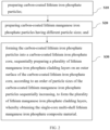
- a single-core multi-shell lithium manganese iron phosphate composite material comprises: a carbon-coated lithium iron phosphate core, and a plurality of lithium manganese iron phosphate cladding layers cladded on an outer surface of the carbon-coated lithium iron phosphate core.
- Each of the plurality of lithium manganese iron phosphate cladding layers comprises lithium manganese iron phosphate particles and a carbon material coated on the lithium manganese iron phosphate particles.
- the lithium manganese iron phosphate particles in the plurality of the lithium manganese iron phosphate cladding layers have particle sizes increase in a radial direction from inside to outside.
- a method for preparing a single-core multi-shell lithium manganese iron phosphate composite material comprises the following steps:
- a cathode material of the secondary battery contains the above-mentioned single-core multi-shell lithium manganese iron phosphate composite material, or contains a single-core multi-shell lithium manganese iron phosphate composite material prepared by the above method.
- lithium iron phosphate in the form of a large-sized particle is used as a core carrier, thus having good high-rate performance, excellent low-temperature performance, high compaction density, and excellent cycle performance, long service life, high energy retention rate, good structural stability, and high safety performance.
- multi-layer cladding technology is used to form a plurality of lithium manganese iron phosphate cladding layers on the outer surface of the core, so as to achieve higher voltage platform and energy density.
- the cladding layers comprise lithium manganese iron phosphate particles and carbon materials
- the coating of the lithium manganese iron phosphate particles with the carbon material can not only effectively control the size of lithium manganese iron phosphate particles, avoid the formation of large particles during the treatments, but also effectively improve the conductivity of lithium manganese iron phosphate particles, thereby improving the electrochemical properties of the composite material.
- the carbon material covering the lithium manganese iron phosphate particles plays a role of compact filling among the lithium manganese iron phosphate particles, which can effectively improve the compaction density of the composite material.
- the particle sizes of lithium manganese iron phosphate particles in the plurality of lithium manganese iron phosphate cladding layers increase radially from inside to outside. Due to the long conduction distance of carriers in the inner layer of the composite material, the cladding layer close to the core adopts lithium manganese iron phosphate particles with smaller particle sizes, which is beneficial to improve the discharge efficiency of the composite material; while the carriers in the outer layer of the composite material has a short conduction distance, so compared with the inner cladding layer, the outer cladding layer uses lithium manganese iron phosphate particles with relatively large particle sizes, which is beneficial to improve the compaction density of the composite material.
- the preparation method of the single-core multi-shell lithium manganese iron phosphate composite material provided in embodiments of the present application are summarized as follows: the carbon-coated lithium iron phosphate particles and carbon-coated lithium manganese iron phosphate particles having different particle sizes are respectively prepared, in which, carbon coating is not only beneficial to improve the electrical conductivity of the material, but also to maintain the particle sizes of lithium iron phosphate particles and the particle sizes of the lithium manganese iron phosphate particles, which avoids the aggregation and growth of particles in the subsequent preparation process.
- the carbon-coated lithium iron phosphate particles are formed into the core, and a plurality of lithium manganese iron phosphate cladding layers are sequentially prepared on an outer surface of the core using the multi-layer cladding technology, according to an order of particle sizes of the carbon-coated lithium manganese iron phosphate particles sequentially increasing, to form the plurality of lithium manganese iron phosphate cladding layers according to a particle size gradient.
- the preparation process is simple, suitable for large-scale industrial production and application, and the carbon-coated lithium iron phosphate core and the plurality of lithium manganese iron phosphate cladding layers in the preparation of single-core multi-shell lithium iron phosphate composite material play synergistic effect, which makes the composite material have high energy density, electrical conductivity, compaction density, safety, stability, and other electrochemical properties.
- a first aspect of embodiments of the present application provides a single-core multi-shell lithium manganese iron phosphate composite material.
- the composite material comprises: a carbon-coated lithium iron phosphate core, and a plurality of lithium manganese iron phosphate cladding layers cladded on an outer surface of the carbon-coated lithium iron phosphate core.
- Each of the plurality of lithium manganese iron phosphate cladding layers comprises lithium manganese iron phosphate particles and a carbon material coated on the lithium manganese iron phosphate particles.
- the lithium manganese iron phosphate particles in the plurality of the lithium manganese iron phosphate cladding layers have particle sizes increase in a radial direction from inside to outside.
- the carbon-coated lithium iron phosphate is employed as the core, and the plurality of lithium manganese iron phosphate cladding layers are employed as the shell.
- Each of the plurality of lithium manganese iron phosphate cladding layers comprises lithium manganese iron phosphate particles and a carbon material coated on the lithium manganese iron phosphate particles.
- the lithium manganese iron phosphate particles in the plurality of the lithium manganese iron phosphate cladding layers of the shell have the particle sizes increase in the radial direction from inside to outside.
- the composite material in embodiments of the present application adopts lithium iron phosphate in the form of a large-sized particle as the core carrier, which has good high-rate performance, excellent low-temperature performance, high compaction density, and excellent cycle performance, long service life, high energy retention rate, good structural stability, and high safety performance.
- multi-layer cladding technology is used to form a plurality of lithium manganese iron phosphate cladding layers on the outer surface of the core, so as to achieve higher voltage platform and energy density.
- the cladding layers comprise lithium manganese iron phosphate particles and carbon materials
- the coating of the lithium manganese iron phosphate particles with the carbon material can not only effectively control the size of lithium manganese iron phosphate particles, avoid the formation of large particles during the treatments, but also effectively improve the conductivity of lithium manganese iron phosphate particles, thereby improving the electrochemical properties of the composite material.
- the carbon material covering the lithium manganese iron phosphate particles plays a role of compact filling among the lithium manganese iron phosphate particles, which can effectively improve the compaction density of the composite material.
- the particle sizes of lithium manganese iron phosphate particles in the plurality of lithium manganese iron phosphate cladding layers increase radially from inside to outside. Due to the long conduction distance of carriers in the inner layer of the composite material, the cladding layer close to the core adopts lithium manganese iron phosphate particles with smaller particle sizes, which is beneficial to improve the discharge efficiency of the composite material; while the carriers in the outer layer of the composite material has a short conduction distance, so compared with the inner cladding layer, the outer cladding layer uses lithium manganese iron phosphate particles with relatively large particle sizes, which is beneficial to improve the compaction density of the composite material.
- the composite material based on the lithium iron phosphate core and multiple shell layers of lithium manganese iron phosphate, as well as the regular arrangement of the particle sizes, the composite material has high energy density, electrical conductivity, compaction density, safety, stability, and other electrochemical properties.
- a particle size of each of lithium iron phosphate particles is between 500 nm and 900 nm, and a thickness of a carbon coating layer is between 3 nm and 5 nm.
- the lithium iron phosphate particles with such particle sizes are beneficial to the composite material to have better electrical properties and compaction density.
- the thickness of the carbon coating layer can effectively improve the electrical conductivity of the composite material. If the carbon coating layer is too thin, the improvement effect on the electrical conductivity of the composite material is not good. If the carbon coating layer is too thick, the proportion of lithium iron phosphate, lithium manganese iron phosphate and the like in the composite material will reduce, thereby reducing the electrochemical properties of the composite material.
- the particle size of each of the lithium iron phosphate particles in the carbon-coated lithium iron phosphate core includes but is not limited to between 500 nm and 600nm, between 600 nm and 700 nm, between 700 nm and 800 nm, between 800 nm and 900 nm, and the like, and the thickness of the carbon coating layer includes but not limited to between 3 nm and 4 nm, between 4 nm and 5 nm, and the like.
- the particle size of each of the lithium manganese iron phosphate particles is between 50 nm and 300 nm, and a coating thickness of the carbon material is between 3 nm and 10 nm.
- Each of the lithium manganese iron phosphate cladding layer in embodiments of the present application includes lithium manganese iron phosphate particles and a carbon material coated with lithium manganese iron phosphate particles, in which, the lithium manganese iron phosphate particles have the particle sizes of between 50 nm and 300 nm, which, compared with those lithium manganese iron phosphate particles having relatively small particle sizes, can shorten the charge transfer distance and improve the charge transfer efficiency.
- the coating thickness of the carbon material is between 3 nm and 10 nm, which can effectively improve the conductivity of the lithium manganese iron phosphate particles, and can prevent the lithium manganese iron phosphate particles from growing up during the treatment process, thereby being conducive to maintaining the stability of the particle sizes of the lithium manganese iron phosphate particles.
- the particle size of each of the lithium manganese iron phosphate particles in each lithium manganese iron phosphate cladding layer includes but is not limited to between 50 nm and 100 nm, between 100 nm and 150 nm, between 150 nm and 200 nm, between 200 nm and 250 nm, between 250 nm and 300 nm, and the like.
- the coating thickness of the material includes but is not limited to between 3 nm and 4 nm, between 4 nm and 6 nm, between 6 nm and 8 nm, between 8 nm and 10 nm, and the like.
- a mass ratio of lithium iron phosphate particles to the lithium manganese iron phosphate particles is (1 to 50): (300 to 500). This ratio makes the composite material have high energy density, high compaction density, safety, stability, and other electrochemical properties.
- a mass ratio of lithium iron phosphate particles to the lithium manganese iron phosphate particles is 1: (300 to 500). This ratio makes the composite material have better energy density, compaction density, safety, stability, and other electrochemical properties. If the proportion of lithium iron phosphate in the composite material is too high, it is not conducive to improving the performance of the composite material such as voltage platform and energy density. If the proportion of lithium manganese iron phosphate is too high, the shortcomings of lithium's low electrical conductivity and longer lithium ion transport channels make it difficult for the material to release electrical properties.
- the mass ratio of lithium iron phosphate to lithium manganese iron phosphate particles includes but is not limited to 1: (300 to 350), 1: (350 to 400), 1: (400 to 450), 1: (450 to 50), and the like.
- a total thickness of the plurality of lithium manganese iron phosphate cladding layers is between 6.4 ⁇ m and 7.5 ⁇ m.
- the cladding layer of this thickness is not only beneficial to improving the voltage platform of the composite material, the discharge efficiency of the material, and the compaction density of the material, as well as improving the energy density and compaction density of the material, but also avoids the shortcoming of the low release efficiency of the electrical properties of the composite material due to the excessive thickness of the cladding layer.
- the total thickness of the plurality of lithium manganese iron phosphate cladding layers includes, but is not limited to, 6.4, 6.5, 6.6, 6.7, 6.8, 6.9, 7.0, 7.1, 7.2, 7.3, 7.4, 7.5, etc.
- the composite material comprises four lithium manganese iron phosphate cladding layers, which, in the radial direction from inside to outside, are respectively a first lithium manganese iron phosphate cladding layer, a second lithium manganese iron phosphate cladding layer, a third lithium manganese iron phosphate cladding layer, and a fourth lithium manganese iron phosphate cladding layer.
- four lithium manganese iron phosphate cladding layers are cladded on the outer surface of the carbon-coated lithium iron phosphate core, and the particle sizes of lithium manganese iron phosphate particles in the respective cladding layers increase radially from inside to outside.
- the cladding layer close to the core adopts lithium manganese iron phosphate particles with smaller particle sizes, which is beneficial to improve the discharge efficiency of the composite material; while the carriers in the outer layer of the composite material has a short conduction distance, the outer cladding layer uses lithium manganese iron phosphate particles with relatively large particle sizes, which is beneficial to improve the compaction density of the composite material.
- the performance of the lithium manganese iron phosphate cladding layer structure is much better in case of 4 layers.
- the composite material includes four lithium manganese iron phosphate cladding layers, which not only overcomes the disadvantage of poor electrical properties caused by the long conduction distance of the inner layer of the composite material, but also overcomes the disadvantage of rapid compaction reduction due to the improvement of electrical properties.
- a mass ratio of the lithium manganese iron phosphate particles in the first lithium manganese iron phosphate cladding layer, the second lithium manganese iron phosphate cladding layer, the third lithium manganese iron phosphate cladding layer, and the fourth lithium manganese iron phosphate cladding layer is (3 to 5): (9 to 12): (60 to 80): (250 to 350). Due to the low conductivity of lithium manganese iron phosphate, the higher the manganese content, the lower the conductivity, the smaller the particles, the lower the manganese content, and the larger the particles, the higher the manganese content.
- the particle sizes of lithium manganese iron phosphate particles in each cladding layer increase in the radial direction from inside to outside, and the thickness increases sequentially from inside to outside, which is more conducive to improving the electrochemical properties of the composite material.
- the first lithium manganese iron phosphate cladding layer has a thickness of between 400 nm and 600 nm, and the lithium manganese iron phosphate particles in the first lithium manganese iron phosphate cladding layer have particle sizes of between 50 nm and 150 nm.
- the second lithium manganese iron phosphate cladding layer has a thickness of between 900 nm and 1000 nm, and the lithium manganese iron phosphate particles in the second lithium manganese iron phosphate cladding layer have particle sizes of between 100 nm and 200 nm.
- the third lithium manganese iron phosphate cladding layer has a thickness of between 1900 nm and 2000 nm, and the lithium manganese iron phosphate particles in the third lithium manganese iron phosphate cladding layer have particle sizes of between 150 nm and 250 nm.
- the fourth lithium manganese iron phosphate cladding layer has a thickness of between 3900 nm and 4000 nm, and the lithium manganese iron phosphate particles in the fourth lithium manganese iron phosphate cladding layer have particle sizes of between 200 nm and 300 nm. Under cladding layers in such conditions, it is more beneficial to improve the voltage platform of the composite material, improve the energy density, the compaction density, and other electrochemical properties, as well as ensure excellent electrical conductivity of the composite material.
- the single-core multi-shell lithium manganese iron phosphate composite material in embodiments of the present application can be prepared by methods in the following embodiments.
- the second aspect of embodiments of the present application provides a method for preparing a single-core multi-shell lithium manganese iron phosphate composite material.
- the method comprises the following steps:
- the carbon-coated lithium iron phosphate particles and carbon-coated lithium manganese iron phosphate particles having different particle sizes are respectively prepared, in which, carbon coating is not only beneficial to improve the electrical conductivity of the material, but also to maintain the particle sizes of lithium iron phosphate particles and the particle sizes of the lithium manganese iron phosphate particles, which avoids the aggregation and growth of particles in the subsequent preparation process.
- the carbon-coated lithium iron phosphate particles are formed into the core, and a plurality of lithium manganese iron phosphate cladding layers are sequentially prepared on an outer surface of the core using the multi-layer cladding technology, according to an order of particle sizes of the carbon-coated lithium manganese iron phosphate particles sequentially increasing, to form the plurality of lithium manganese iron phosphate cladding layers according to a particle size gradient.
- the preparation process is simple, suitable for large-scale industrial production and application, and the carbon-coated lithium iron phosphate core and the plurality of lithium manganese iron phosphate cladding layers in the preparation of single-core multi-shell lithium iron phosphate composite material play synergistic effect, which makes the composite material have high energy density, electrical conductivity, compaction density, safety, stability, and other electrochemical properties.
- the step of preparing carbon-coated lithium iron phosphate particles comprises: combining lithium iron phosphate with a first carbon source, and performing a first sintering treatment to obtain the carbon-coated lithium iron phosphate particles.
- a carbon coating layer can be formed in situ on the surface of each of the lithium iron phosphate particles, so as to obtain the carbon-coated lithium iron phosphate particles.
- conditions for the first sintering treatment comprise: sintering in an inert atmosphere at a temperature of between 750°C and 800°C for between 5 hrs and 8 hrs.
- the sintering treatment under such conditions is conducive to improving the performance of lithium iron phosphate, and is also beneficial for the carbon material to form a carbon coating layer in situ on the surface of the lithium iron phosphate particle.
- the sintering temperature is too low or the time is too short, it is not conducive to improving the stability of lithium iron phosphate particles, and it is also not conducive to the formation of the carbon coating layer; if the sintering temperature is too high or the time is too long, it will cause the particle sizes of lithium iron phosphate particles being too large, and the electrochemical properties of the material will be affected.
- the first carbon source is at least one selected from sucrose, glucose, oxalic acid, salicylic acid, citric acid, tartaric acid, malic acid, glycine, ethylenediaminetetraacetic acid, and succinic acid.
- sucrose glucose
- oxalic acid salicylic acid
- citric acid tartaric acid
- malic acid glycine
- succinic acid succinic acid
- the mass ratio of lithium iron phosphate to the first carbon source includes but is not limited to 1: (0.1 to 0.3), and this mass ratio is conducive to the formation of lithium iron phosphate having a particle size of between 500 nm and 900 nm and the formation of a carbon coating layer having a thickness of between 3 nm and 5 nm through sintering treatment.
- the lithium iron phosphate particles having such a particle size are conducive to having better electrical properties in the composite material.
- Such thickness of the carbon coating layer can effectively improve the electrical conductivity of the composite material. If the carbon coating layer is too thin, the effect of improving the electrical conductivity of the material is not good. If the carbon coating layer is too thick, the proportion of lithium iron phosphate, lithium manganese iron phosphate, and other materials in the composite material will be reduced, thereby reducing the electrochemical properties of the composite material.
- the step of preparing carbon-coated lithium manganese iron phosphate particles having different particle sizes comprises:
- Temperatures of the second sintering treatment, the third sintering treatment, the fourth sintering treatment, and the fifth sintering treatment sequentially increase and are between 630°C and 800°C.
- the particle sizes of lithium manganese iron phosphate particles can be controlled.
- the sintering temperature between 630°C and 800°C, as the temperatures of the second sintering treatment to the fifth sintering treatment increase sequentially, particle sizes of the obtained first carbon-coated lithium manganese iron phosphate particles to the fourth carbon-coated lithium manganese iron phosphate particles increase sequentially.
- conditions for the second sintering treatment comprise: sintering in an inert atmosphere at a temperature of between 630°C and 650°C for between 5 hrs and 8 hrs.
- the carbon source can form a coating layer on the surface of the lithium manganese iron phosphate in situ.
- the particle size of each of the lithium manganese iron phosphate particles is between 50 nm and 150 nm, and the thickness of each carbon coating layer is between 3 nm and 5 nm.
- the lithium manganese iron phosphate particle having a small particle size has a short charge transfer path and high charge transfer efficiency.
- the carbon coating layer generated in situ can not only improve the electrical conductivity, but also help limit the continuous growth of lithium manganese iron phosphate particle sizes and help maintain the particle sizes.
- conditions for the third sintering treatment comprise: sintering in an inert atmosphere at a temperature of between 650°C and 680°C for between 5 hrs and 8 hrs.
- the particle size of each lithium manganese iron phosphate particle is between 100 nm and 200 nm, and the thickness of each carbon coating layer is between 3 nm and 5 nm.
- the lithium manganese iron phosphate particle having a small particle size has a short charge transfer path and high charge transfer efficiency.
- the carbon coating layer generated in situ can not only improve the electrical conductivity, but also help limit the continuous growth of lithium manganese iron phosphate particle size and help maintain the particle size.
- conditions for the fourth sintering treatment comprise: sintering in an inert atmosphere at a temperature of between 700°C and 730°C for between 5 hrs and 8 hrs.
- the particle size of each lithium manganese iron phosphate particle is between 150 nm and 250 nm, and the thickness of each carbon coating layer is between 3 nm and 5 nm.
- Particles having such particle size when being used as the third cladding layer, is conductive to improving the tap density of the composite material, and the carbon coating layer generated in situ can not only improve the electrical conductivity, but also help limit the continuous growth of lithium manganese iron phosphate particle size and help maintain the particle size.
- conditions for the fifth sintering treatment comprise: sintering in an inert atmosphere at a temperature of between 750°C and 800°C for between 5 hrs and 8 hrs.
- the particle size of each lithium manganese iron phosphate particle is between 200 nm and 300 nm, and the thickness of the carbon coating layer is between 3 nm and 5 nm.
- Particles having such particle size when being used as the third cladding layer, is conductive to improving the tap density of the composite material, and the carbon coating layer generated in situ can not only improve the electrical conductivity, but also help limit the continuous growth of lithium manganese iron phosphate particle size and help maintain the particle size.
- each of the second carbon source, the third carbon source, the fourth carbon source, and the fifth carbon source is independently at least one selected from sucrose, glucose, oxalic acid, salicylic acid, citric acid, tartaric acid, malic acid, glycine, ethylenediaminetetraacetic acid, and succinic acid.
- These carbon sources can be converted into gaseous hydrocarbons during the high-temperature sintering treatment, and a carbon coating layer is deposited on the surface of the lithium manganese iron phosphate particles to improve the particle size stability and electrical conductivity of the particles.
- the step of sequentially preparing a plurality of lithium manganese iron phosphate cladding layers on an outer surface of the carbon-coated lithium iron phosphate core comprises:
- Embodiments of the present application adopt multi-layer cladding technology to make the first carbon-coated lithium manganese iron phosphate particles to the fourth carbon-coated lithium manganese iron phosphate particles with particle sizes ranging from small to large be sequentially cladded on the outer surface of the carbon-coated lithium iron phosphate core, so as to form the first lithium manganese iron phosphate cladding layer, the second lithium manganese iron phosphate cladding layer, the third lithium manganese iron phosphate cladding layer, and the fourth lithium manganese iron phosphate cladding layer sequentially.
- a mass ratio of the first carbon-coated lithium manganese iron phosphate particles, the second carbon-coated lithium manganese iron phosphate particles, the third carbon-coated lithium manganese iron phosphate particles, the fourth carbon-coated lithium manganese iron phosphate particles is (3 to 5): (9 to 12): (60 to 80): (250 to 350). Due to the low conductivity of lithium manganese iron phosphate, the higher the manganese content, the lower the conductivity, the smaller the particles, the lower the manganese content, and the larger the particles, the higher the manganese content.
- the particle sizes of lithium manganese iron phosphate particles in each cladding layer increase in the radial direction from inside to outside, and the thickness increases sequentially from inside to outside, which is more conducive to improving the electrochemical properties of the composite material.
- each of the sixth carbon source, the seventh carbon source, the eighth carbon source, and the ninth carbon source is independently at least one selected from sucrose, glucose, oxalic acid, salicylic acid, citric acid, tartaric acid, malic acid, glycine, ethylenediaminetetraacetic acid, and succinic acid.
- conditions for each of the sixth sintering treatment, the seventh sintering treatment, the eighth sintering treatment, and the ninth sintering treatment independently comprise: sintering in an inert atmosphere at a temperature of between 600°C and 650°C for between 2 hrs and 5 hrs. Under this condition, a stable lithium manganese iron phosphate cladding layer can be formed.
- a third aspect of the embodiment of the present application provides a secondary battery, the cathode material of the secondary battery contains the single-core multi-shell manganese iron phosphate composite material as described in the above, or contains the single-core multi-shell manganese phosphate composite material prepared by the method as described in the above.
- the secondary battery provided by the third aspect of embodiments of the present application contains the above-mentioned single-core multi-shell lithium manganese iron phosphate composite material, which has high energy density, electrical conductivity, compaction density, safety, stability, and other electrochemical properties, the electrochemical properties of the secondary battery is improved.
- a single-core multi-shell lithium manganese iron phosphate composite material was prepared by the following steps:
- a single-core multi-shell lithium manganese iron phosphate composite material was prepared by the following steps:
- a single-core multi-shell lithium manganese iron phosphate composite material was prepared by the following steps:
- a single-core multi-shell lithium manganese iron phosphate composite material was prepared by the following steps:
- a single-core multi-shell lithium manganese iron phosphate composite material was prepared by the following steps:
- a single-core multi-shell lithium manganese iron phosphate composite material was prepared by the following steps:
- a single-core multi-shell lithium manganese iron phosphate composite material was prepared by the following steps:
- the battery was assembled as follows: Preparation of the cathode plate: LFMP, conductive carbon black (SP), polyvinylidene fluoride (PVDF), and N-methylpyrrolidone (NMP) were mixed evenly with a ball mill mixer for 2 hrs at a mass ratio of 93.5:2.5:4: 100 to obtain cathode slurry; the prepared cathode slurry was applied onto an aluminum foil, evenly scraped with a scraper, dried at 130°C, and then rolled, so as to obtain the cathode plate.
- LFMP conductive carbon black
- PVDF polyvinylidene fluoride
- NMP N-methylpyrrolidone
- the prepared cathode was attached to a cathode metal shell via a conductive adhesive, a metal lithium sheet was used as an anode, a Celgard 2400 microporous membrane was used as a separator, and 1.0 mol/L LiPF 6 solution was adopted as an electrolyte.
- a solvent of the electrolyte is a mixture of ethylene carbonate (EC), diethyl carbonate (DEC), and ethyl methyl carbonate (EMC) with a volume ratio of 1:1:1, and a button cell was assembled in a glove box.
- Test Items Test Items 0.1 C Discharge mAh ⁇ g-1 (25°C) 0.1 C Specific energy wh/kg (25°C) 1C Specific energy wh/kg (25°C) Resistivity ( ⁇ . cm)
- Example 1 155.3 581.3 543.6 5.3
- Example 2 153.5 568.6 518.3 6.4
- Example 3 154.8 578.4 536.2 3.9
- Example 4 149.3 552.3 493.6 4.3
- Example 6 153.1 565.4 521.2 1.4 Comparative Example 1 89.3 334.1 287.3 13652
- the single-core multi-shell lithium manganese iron phosphate composite material prepared in the examples of the present application has excellent electrochemical properties, including electrical conductivity, energy density, and compaction density, especially the single-core multi-shell manganese iron phosphate composite material prepared in Examples 1-3 exhibits more excellent electrochemical properties due to the particle size of the material.
- the number of the cladding layers reduces (Example 4)
- the number of cladding layers increases (Example 5)
- the thickness of the carbon coating layers increases (Example 6)
- the electrochemical properties of the composite material will be reduced to a certain extent.
- the thickness of the cladding layers is the same, too thick the inner layer of particles may result in that the electrical properties cannot be released; therefore, the thickness of the cladding layers increases from inside to outside.
- the number of cladding layers is greater than four, the cladded particle is too large in such condition, and the electrical properties released by the particles inside the material are reduced due to the longer conduction distance.
- the compaction density is low because the cladding particles are too small.
- no carbon material was added in the preparation process of Comparative Example 1, and no carbon coating layer was formed on the surface of lithium iron phosphate and lithium manganese iron phosphate, the electrochemical properties of the composite material such as electrical conductivity, energy density, and compaction density were significantly reduced.
Landscapes
- Chemical & Material Sciences (AREA)
- Chemical Kinetics & Catalysis (AREA)
- Electrochemistry (AREA)
- General Chemical & Material Sciences (AREA)
- Inorganic Chemistry (AREA)
- Engineering & Computer Science (AREA)
- Organic Chemistry (AREA)
- Composite Materials (AREA)
- Materials Engineering (AREA)
- Crystallography & Structural Chemistry (AREA)
- Nanotechnology (AREA)
- Manufacturing & Machinery (AREA)
- Physics & Mathematics (AREA)
- Condensed Matter Physics & Semiconductors (AREA)
- General Physics & Mathematics (AREA)
- Battery Electrode And Active Subsutance (AREA)
Applications Claiming Priority (2)
| Application Number | Priority Date | Filing Date | Title |
|---|---|---|---|
| CN202210309750.1A CN114843507B (zh) | 2022-03-28 | 2022-03-28 | 单核多壳磷酸锰铁锂正极材料及制备方法、二次电池 |
| PCT/CN2023/083117 WO2023185591A1 (zh) | 2022-03-28 | 2023-03-22 | 单核多壳磷酸锰铁锂复合材料及其制备方法、二次电池 |
Publications (2)
| Publication Number | Publication Date |
|---|---|
| EP4354549A1 true EP4354549A1 (de) | 2024-04-17 |
| EP4354549A4 EP4354549A4 (de) | 2025-12-10 |
Family
ID=82563924
Family Applications (1)
| Application Number | Title | Priority Date | Filing Date |
|---|---|---|---|
| EP23754096.8A Pending EP4354549A4 (de) | 2022-03-28 | 2023-03-22 | Einkern-mehrschalen-lithiummangan-eisenphosphat-verbundmaterial und herstellungsverfahren dafür sowie sekundärbatterie |
Country Status (4)
| Country | Link |
|---|---|
| US (1) | US20250054947A1 (de) |
| EP (1) | EP4354549A4 (de) |
| CN (1) | CN114843507B (de) |
| WO (1) | WO2023185591A1 (de) |
Cited By (2)
| Publication number | Priority date | Publication date | Assignee | Title |
|---|---|---|---|---|
| WO2026041886A1 (en) * | 2024-08-21 | 2026-02-26 | Borsodchem Zrt | Lithium iron manganese phosphate composite material and preparation method therefor as well as secondary battery |
| WO2026069096A1 (ja) * | 2024-09-27 | 2026-04-02 | 株式会社半導体エネルギー研究所 | 正極、正極の作製方法 |
Families Citing this family (13)
| Publication number | Priority date | Publication date | Assignee | Title |
|---|---|---|---|---|
| CN114843507B (zh) * | 2022-03-28 | 2023-04-11 | 佛山市德方纳米科技有限公司 | 单核多壳磷酸锰铁锂正极材料及制备方法、二次电池 |
| TWI838075B (zh) * | 2023-01-11 | 2024-04-01 | 台灣立凱電能科技股份有限公司 | 碳包覆磷酸鋰鐵材料的製造方法 |
| CN116154137A (zh) * | 2023-03-07 | 2023-05-23 | 蜂巢能源科技股份有限公司 | 一种复合磷酸锰铁锂正极材料及其制备方法和应用 |
| WO2024192629A1 (zh) * | 2023-03-20 | 2024-09-26 | 广东邦普循环科技有限公司 | 一种磷酸锰铁锂材料及其前驱体与制备方法、锂离子电池 |
| TWI838175B (zh) * | 2023-03-21 | 2024-04-01 | 台灣立凱電能科技股份有限公司 | 碳包覆磷酸鋰鐵材料的製造方法 |
| CN118867146B (zh) * | 2023-04-27 | 2026-01-13 | 宁德时代新能源科技股份有限公司 | 正极活性材料及其制备方法、电极组件、电池和用电装置 |
| CN117117153B (zh) * | 2023-10-16 | 2024-02-20 | 宁波容百新能源科技股份有限公司 | 一种正极材料及其制备方法、锂离子电池 |
| WO2025264061A1 (ko) * | 2024-06-21 | 2025-12-26 | 주식회사 엘지화학 | 양극 활물질, 이를 포함하는 양극 및 리튬 이차전지 |
| CN118825237A (zh) * | 2024-08-02 | 2024-10-22 | 合肥国轩高科动力能源有限公司 | 改性磷酸锰铁锂正极材料、其制备方法及锂离子电池 |
| CN119208567B (zh) * | 2024-09-27 | 2025-10-17 | 福建龙净储能电池有限公司 | 一种磷酸锰铁锂材料及其制备方法和应用 |
| CN119118094B (zh) * | 2024-11-14 | 2025-04-29 | 上海量孚新能源科技有限公司 | 磷酸锰铁锂复合材料及其制备方法、含其的锂离子电池 |
| CN119330327B (zh) * | 2024-12-18 | 2025-03-07 | 湖南裕能新能源电池材料股份有限公司 | 一种磷酸锰铁锂复合材料及其制备方法和应用 |
| CN120172377B (zh) * | 2025-05-16 | 2025-08-05 | 江苏正力新能电池技术股份有限公司 | 磷酸铁锂正极材料的制备方法、正极材料、极片及电池 |
Family Cites Families (11)
| Publication number | Priority date | Publication date | Assignee | Title |
|---|---|---|---|---|
| US20140057164A1 (en) * | 2012-05-02 | 2014-02-27 | Fastcap Systems Corporation | Enhanced carbon based electrode for use in energy storage devices |
| CN105810897B (zh) * | 2014-12-31 | 2019-04-19 | 比亚迪股份有限公司 | 一种锂离子电池复合材料及其制备方法、包含该复合材料的正极材料 |
| JP6500578B2 (ja) * | 2015-04-27 | 2019-04-17 | 株式会社デンソー | 非水電解質二次電池用電極活物質及びその製造方法、並びに非水電解質二次電池 |
| CN106340639B (zh) * | 2016-10-28 | 2019-07-12 | 合肥国轩高科动力能源有限公司 | 一种磷酸铁锂/碳包覆的核壳型磷酸锰铁锂复合正极材料及其制备方法 |
| CN109888205A (zh) * | 2019-01-18 | 2019-06-14 | 北方奥钛纳米技术有限公司 | 纳微球形碳包覆磷酸锰铁锂复合材料及制备方法、锂电池正极材料、锂电池 |
| CN109888281A (zh) * | 2019-03-19 | 2019-06-14 | 山西沃特海默新材料科技股份有限公司 | 一种双层包覆的磷酸铁锂正极材料及其制备方法 |
| JP7532906B2 (ja) * | 2019-06-28 | 2024-08-14 | 東レ株式会社 | リチウムイオン二次電池用正極 |
| JP7516557B2 (ja) * | 2020-06-17 | 2024-07-16 | ジーアールエスティー・インターナショナル・リミテッド | 複合材剥離方法 |
| CN113270575A (zh) * | 2021-05-06 | 2021-08-17 | 宁夏百川新材料有限公司 | 一种包覆三元磷酸锰铁锂复合材料及其制备方法 |
| CN114843507B (zh) * | 2022-03-28 | 2023-04-11 | 佛山市德方纳米科技有限公司 | 单核多壳磷酸锰铁锂正极材料及制备方法、二次电池 |
| CN116154137A (zh) * | 2023-03-07 | 2023-05-23 | 蜂巢能源科技股份有限公司 | 一种复合磷酸锰铁锂正极材料及其制备方法和应用 |
-
2022
- 2022-03-28 CN CN202210309750.1A patent/CN114843507B/zh active Active
-
2023
- 2023-03-22 US US18/278,488 patent/US20250054947A1/en active Pending
- 2023-03-22 EP EP23754096.8A patent/EP4354549A4/de active Pending
- 2023-03-22 WO PCT/CN2023/083117 patent/WO2023185591A1/zh not_active Ceased
Cited By (2)
| Publication number | Priority date | Publication date | Assignee | Title |
|---|---|---|---|---|
| WO2026041886A1 (en) * | 2024-08-21 | 2026-02-26 | Borsodchem Zrt | Lithium iron manganese phosphate composite material and preparation method therefor as well as secondary battery |
| WO2026069096A1 (ja) * | 2024-09-27 | 2026-04-02 | 株式会社半導体エネルギー研究所 | 正極、正極の作製方法 |
Also Published As
| Publication number | Publication date |
|---|---|
| CN114843507A (zh) | 2022-08-02 |
| US20250054947A1 (en) | 2025-02-13 |
| EP4354549A4 (de) | 2025-12-10 |
| CN114843507B (zh) | 2023-04-11 |
| WO2023185591A1 (zh) | 2023-10-05 |
Similar Documents
| Publication | Publication Date | Title |
|---|---|---|
| EP4354549A1 (de) | Einkern-mehrschalen-lithiummangan-eisenphosphat-verbundmaterial und herstellungsverfahren dafür sowie sekundärbatterie | |
| CN109390563B (zh) | 改性磷酸铁锂正极材料及其制备方法、正极片、锂二次电池 | |
| US12494481B2 (en) | Core-shell composite negative electrode material, preparation method therefor and use thereof | |
| EP3557668A1 (de) | Ternäres material und herstellungsverfahren dafür, batterieschlämme, positivelektrode und lithiumbatterie | |
| EP4546444A1 (de) | Sekundärbatterie und elektrische vorrichtung | |
| KR101865381B1 (ko) | 리튬 이차 전지 및 이의 제조방법 | |
| CN112701281B (zh) | 复合橄榄石结构正极材料及其制备方法与应用 | |
| EP4407715A1 (de) | Positivelektrodenmaterialzusammensetzung, positivelektrodenfolie und herstellungsverfahren dafür, batterie und elektrische vorrichtung | |
| US20250006921A1 (en) | Lithium-containing multi-phosphate cathode material, preparation method therefor, and secondary battery | |
| CN110957477B (zh) | 一种多孔陶瓷复合锂金属负极及其制备方法 | |
| KR20150065041A (ko) | 리튬 이차 전지용 음극 활물질, 이의 제조 방법 및 이를 포함하는 리튬 이차 전지 | |
| KR101895903B1 (ko) | 리튬 이차 전지용 양극 활물질 및 이를 포함하는 리튬 이차 전지 | |
| CN116314759A (zh) | 高镍正极材料及其制备方法、锂离子电池 | |
| WO2021258275A1 (zh) | 二次电池和包含该二次电池的装置 | |
| CN109980221B (zh) | 一种高压锂离子电池正极材料及其制备方法和应用 | |
| CN115763715A (zh) | 一种BixSey/C复合材料及其制备方法和应用、调控该复合材料铋硒原子比的方法 | |
| CN116544368B (zh) | 一种复合正极材料及其制备方法和锂离子电池 | |
| CN116014103B (zh) | 一种高镍三元正极材料及其制备方法和应用 | |
| CN115810757B (zh) | 一种正极活性材料及含有该正极活性材料的锂离子电池 | |
| CN102044660A (zh) | 稀土元素钐掺杂改性的锂离子电池正极材料及其制备方法 | |
| CN117393717A (zh) | 一种锂离子电池正极材料及其制备方法与应用 | |
| CN117154058A (zh) | 一种双层包覆磷酸铁钠-磷酸钒钠正极材料及其制备方法和应用 | |
| US11024872B2 (en) | Cathode material having an active component and a sodium salt dispersed in the active component, method for preparing the same, cathode and lithium ion battery | |
| KR102033113B1 (ko) | 금속복합체, 이를 포함하는 양극활물질, 이차전지 및 이들의 제조방법 | |
| CN115881937B (zh) | 钙钛矿型金属氧化物负极材料及其制备方法以及负极极片和锂电池 |
Legal Events
| Date | Code | Title | Description |
|---|---|---|---|
| STAA | Information on the status of an ep patent application or granted ep patent |
Free format text: STATUS: UNKNOWN |
|
| STAA | Information on the status of an ep patent application or granted ep patent |
Free format text: STATUS: THE INTERNATIONAL PUBLICATION HAS BEEN MADE |
|
| PUAI | Public reference made under article 153(3) epc to a published international application that has entered the european phase |
Free format text: ORIGINAL CODE: 0009012 |
|
| STAA | Information on the status of an ep patent application or granted ep patent |
Free format text: STATUS: REQUEST FOR EXAMINATION WAS MADE |
|
| 17P | Request for examination filed |
Effective date: 20230822 |
|
| AK | Designated contracting states |
Kind code of ref document: A1 Designated state(s): AL AT BE BG CH CY CZ DE DK EE ES FI FR GB GR HR HU IE IS IT LI LT LU LV MC ME MK MT NL NO PL PT RO RS SE SI SK SM TR |
|
| DAV | Request for validation of the european patent (deleted) | ||
| DAX | Request for extension of the european patent (deleted) | ||
| A4 | Supplementary search report drawn up and despatched |
Effective date: 20251110 |
|
| RIC1 | Information provided on ipc code assigned before grant |
Ipc: H01M 4/58 20100101AFI20251104BHEP Ipc: H01M 4/36 20060101ALI20251104BHEP Ipc: H01M 4/62 20060101ALI20251104BHEP Ipc: H01M 10/0525 20100101ALI20251104BHEP Ipc: C01B 25/45 20060101ALI20251104BHEP Ipc: C01B 32/15 20170101ALI20251104BHEP Ipc: B82Y 30/00 20110101ALI20251104BHEP |