EP4354133A1 - Wellenbewegungsanalysevorrichtung, abtastvorrichtung, wellenbewegungsanalysesystem, wellenbewegungsanalyseverfahren und programm - Google Patents
Wellenbewegungsanalysevorrichtung, abtastvorrichtung, wellenbewegungsanalysesystem, wellenbewegungsanalyseverfahren und programm Download PDFInfo
- Publication number
- EP4354133A1 EP4354133A1 EP22819899.0A EP22819899A EP4354133A1 EP 4354133 A1 EP4354133 A1 EP 4354133A1 EP 22819899 A EP22819899 A EP 22819899A EP 4354133 A1 EP4354133 A1 EP 4354133A1
- Authority
- EP
- European Patent Office
- Prior art keywords
- multiple reflection
- data
- inspection object
- unit
- wave motion
- Prior art date
- Legal status (The legal status is an assumption and is not a legal conclusion. Google has not performed a legal analysis and makes no representation as to the accuracy of the status listed.)
- Granted
Links
Images


Classifications
-
- G—PHYSICS
- G06—COMPUTING OR CALCULATING; COUNTING
- G06T—IMAGE DATA PROCESSING OR GENERATION, IN GENERAL
- G06T7/00—Image analysis
- G06T7/0002—Inspection of images, e.g. flaw detection
- G06T7/0004—Industrial image inspection
-
- G—PHYSICS
- G01—MEASURING; TESTING
- G01N—INVESTIGATING OR ANALYSING MATERIALS BY DETERMINING THEIR CHEMICAL OR PHYSICAL PROPERTIES
- G01N29/00—Investigating or analysing materials by the use of ultrasonic, sonic or infrasonic waves; Visualisation of the interior of objects by transmitting ultrasonic or sonic waves through the object
- G01N29/04—Analysing solids
- G01N29/06—Visualisation of the interior, e.g. acoustic microscopy
- G01N29/0654—Imaging
- G01N29/0672—Imaging by acoustic tomography
-
- G—PHYSICS
- G01—MEASURING; TESTING
- G01N—INVESTIGATING OR ANALYSING MATERIALS BY DETERMINING THEIR CHEMICAL OR PHYSICAL PROPERTIES
- G01N29/00—Investigating or analysing materials by the use of ultrasonic, sonic or infrasonic waves; Visualisation of the interior of objects by transmitting ultrasonic or sonic waves through the object
- G01N29/04—Analysing solids
- G01N29/043—Analysing solids in the interior, e.g. by shear waves
-
- G—PHYSICS
- G01—MEASURING; TESTING
- G01N—INVESTIGATING OR ANALYSING MATERIALS BY DETERMINING THEIR CHEMICAL OR PHYSICAL PROPERTIES
- G01N29/00—Investigating or analysing materials by the use of ultrasonic, sonic or infrasonic waves; Visualisation of the interior of objects by transmitting ultrasonic or sonic waves through the object
- G01N29/04—Analysing solids
- G01N29/06—Visualisation of the interior, e.g. acoustic microscopy
- G01N29/0654—Imaging
- G01N29/069—Defect imaging, localisation and sizing using, e.g. time of flight diffraction [TOFD], synthetic aperture focusing technique [SAFT], Amplituden-Laufzeit-Ortskurven [ALOK] technique
-
- G—PHYSICS
- G01—MEASURING; TESTING
- G01N—INVESTIGATING OR ANALYSING MATERIALS BY DETERMINING THEIR CHEMICAL OR PHYSICAL PROPERTIES
- G01N29/00—Investigating or analysing materials by the use of ultrasonic, sonic or infrasonic waves; Visualisation of the interior of objects by transmitting ultrasonic or sonic waves through the object
- G01N29/04—Analysing solids
- G01N29/11—Analysing solids by measuring attenuation of acoustic waves
-
- G—PHYSICS
- G01—MEASURING; TESTING
- G01N—INVESTIGATING OR ANALYSING MATERIALS BY DETERMINING THEIR CHEMICAL OR PHYSICAL PROPERTIES
- G01N29/00—Investigating or analysing materials by the use of ultrasonic, sonic or infrasonic waves; Visualisation of the interior of objects by transmitting ultrasonic or sonic waves through the object
- G01N29/22—Details, e.g. general constructional or apparatus details
- G01N29/26—Arrangements for orientation or scanning by relative movement of the head and the sensor
- G01N29/265—Arrangements for orientation or scanning by relative movement of the head and the sensor by moving the sensor relative to a stationary material
-
- G—PHYSICS
- G01—MEASURING; TESTING
- G01N—INVESTIGATING OR ANALYSING MATERIALS BY DETERMINING THEIR CHEMICAL OR PHYSICAL PROPERTIES
- G01N29/00—Investigating or analysing materials by the use of ultrasonic, sonic or infrasonic waves; Visualisation of the interior of objects by transmitting ultrasonic or sonic waves through the object
- G01N29/44—Processing the detected response signal, e.g. electronic circuits specially adapted therefor
- G01N29/46—Processing the detected response signal, e.g. electronic circuits specially adapted therefor by spectral analysis, e.g. Fourier analysis or wavelet analysis
-
- G06T12/20—
-
- G—PHYSICS
- G01—MEASURING; TESTING
- G01N—INVESTIGATING OR ANALYSING MATERIALS BY DETERMINING THEIR CHEMICAL OR PHYSICAL PROPERTIES
- G01N2291/00—Indexing codes associated with group G01N29/00
- G01N2291/02—Indexing codes associated with the analysed material
- G01N2291/023—Solids
-
- G—PHYSICS
- G01—MEASURING; TESTING
- G01N—INVESTIGATING OR ANALYSING MATERIALS BY DETERMINING THEIR CHEMICAL OR PHYSICAL PROPERTIES
- G01N2291/00—Indexing codes associated with group G01N29/00
- G01N2291/02—Indexing codes associated with the analysed material
- G01N2291/023—Solids
- G01N2291/0231—Composite or layered materials
-
- G—PHYSICS
- G01—MEASURING; TESTING
- G01N—INVESTIGATING OR ANALYSING MATERIALS BY DETERMINING THEIR CHEMICAL OR PHYSICAL PROPERTIES
- G01N2291/00—Indexing codes associated with group G01N29/00
- G01N2291/02—Indexing codes associated with the analysed material
- G01N2291/028—Material parameters
- G01N2291/0289—Internal structure, e.g. defects, grain size, texture
-
- G—PHYSICS
- G01—MEASURING; TESTING
- G01N—INVESTIGATING OR ANALYSING MATERIALS BY DETERMINING THEIR CHEMICAL OR PHYSICAL PROPERTIES
- G01N2291/00—Indexing codes associated with group G01N29/00
- G01N2291/04—Wave modes and trajectories
-
- G—PHYSICS
- G01—MEASURING; TESTING
- G01N—INVESTIGATING OR ANALYSING MATERIALS BY DETERMINING THEIR CHEMICAL OR PHYSICAL PROPERTIES
- G01N2291/00—Indexing codes associated with group G01N29/00
- G01N2291/04—Wave modes and trajectories
- G01N2291/044—Internal reflections (echoes), e.g. on walls or defects
-
- G—PHYSICS
- G01—MEASURING; TESTING
- G01N—INVESTIGATING OR ANALYSING MATERIALS BY DETERMINING THEIR CHEMICAL OR PHYSICAL PROPERTIES
- G01N2291/00—Indexing codes associated with group G01N29/00
- G01N2291/10—Number of transducers
- G01N2291/106—Number of transducers one or more transducer arrays
-
- G—PHYSICS
- G06—COMPUTING OR CALCULATING; COUNTING
- G06T—IMAGE DATA PROCESSING OR GENERATION, IN GENERAL
- G06T2207/00—Indexing scheme for image analysis or image enhancement
- G06T2207/10—Image acquisition modality
- G06T2207/10072—Tomographic images
- G06T2207/10088—Magnetic resonance imaging [MRI]
-
- G—PHYSICS
- G06—COMPUTING OR CALCULATING; COUNTING
- G06T—IMAGE DATA PROCESSING OR GENERATION, IN GENERAL
- G06T2207/00—Indexing scheme for image analysis or image enhancement
- G06T2207/10—Image acquisition modality
- G06T2207/10132—Ultrasound image
-
- G—PHYSICS
- G06—COMPUTING OR CALCULATING; COUNTING
- G06T—IMAGE DATA PROCESSING OR GENERATION, IN GENERAL
- G06T2207/00—Indexing scheme for image analysis or image enhancement
- G06T2207/20—Special algorithmic details
- G06T2207/20048—Transform domain processing
- G06T2207/20056—Discrete and fast Fourier transform, [DFT, FFT]
-
- G—PHYSICS
- G06—COMPUTING OR CALCULATING; COUNTING
- G06T—IMAGE DATA PROCESSING OR GENERATION, IN GENERAL
- G06T2207/00—Indexing scheme for image analysis or image enhancement
- G06T2207/30—Subject of image; Context of image processing
- G06T2207/30108—Industrial image inspection
Definitions
- the present disclosure relates to a wave motion analysis device, a scanning device, and a method thereof, and more particularly, to a method of detecting defects such as foreign matters and peeling using multiple reflection.
- An ultrasonic scanning method is a method in which an ultrasonic wave is transmitted from a probe (ultrasonic probe) into an inspection object, a reflection wave of the ultrasonic wave generated from a difference in acoustic impedance in the inspection object structure is received, and an ultrasonic tomographic image showing a state of the inside of the inspection object is generated on the basis of an obtained electric signal and inspected (for example, Non Patent Literature 1).
- Patent Literature 1 proposes a technique for performing ultrasonic inspection by removing noise due to multiple echoes generated in the inside of a rotation body of an ultrasonic probe from a received ultrasonic signal.
- Non Patent Literature 1 Masayasu Ito, Tsuyoshi Mochizuki, "Ultrasonic Diagnostic Apparatus”, published by Corona Publishing Co., Ltd., August 26, 2002
- Patent Literature 1 Japanese Patent Application Laid-Open No. 2010-175519
- CFRP Carbon Fiber Reinforced Plastics
- a composite material such as CFRP often has a layer structure in which thin plate-shaped members are laminated, and in adhesion/bonding failure of members and quality evaluation of surface coating, defects such as peeling and foreign matters to be inspected are often located in a shallow portion of the member to be inspected. Therefore, when these defects are detected using the ultrasonic scanning method, there is a problem that it is difficult to accurately detect the defect since the reflection signal from the defect is buried in the specular reflection component such as surface reflection having a high signal intensity in the shallow portion, and the signal from the defect cannot be accurately identified.
- the inspection target is a defect such as interlayer adhesion/bonding failure in a thin plate material forming a layer structure, peeling, foreign matters, or voids in surface coating
- a defect substantially perpendicular to the incident direction of the beam is a strong reflector, and thus a virtual image (artifact) due to multiple reflection occurs, which makes it difficult to perform more accurate measurement.
- Patent Literature 1 it has been a technical common sense that the artifact due to multiple reflection is removed as noise that hinders inspection.
- the present disclosure has been made in view of the above problems, and an object of the present disclosure is to provide a wave motion analysis device, a scanning device, a wave motion analysis system, a wave motion analysis method, and a program capable of detecting a defect located in a shallow portion of an inspection object member even when surface reflection is present.
- a wave motion analysis device is a wave motion analysis device that detects a defect of an inspection object on the basis of a reflection wave obtained from the inspection object, the wave motion analysis device including: a multiple reflection area extraction unit that acquires tomographic data generated on the basis of the reflection wave and extracts a multiple reflection area from the tomographic data; and a detection unit that detects a multiple reflection image corresponding to the defect of the inspection object from the extracted multiple reflection area.
- a wave motion analysis device a scanning device, a wave motion analysis system, a wave motion analysis method, and a program capable of detecting a defect located in a shallow portion of an inspection object member even when surface reflection is present.
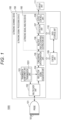
- Fig. 1 is a functional block diagram of an ultrasonic scanning device set 1000 according to the first embodiment.
- the ultrasonic scanning device set 1000 includes a probe 101 (ultrasonic probe) having a plurality of vibrators 101a that transmit ultrasonic waves toward an inspection object and receive reflection of the ultrasonic waves, an ultrasonic scanning device 100 that causes the probe 101 to transmit and receive ultrasonic waves and generates image data on the basis of an output signal from the probe 101, and a display unit 111 that displays an ultrasonic image on a screen.
- Each of the probe 101 and the display unit 111 is configured to be connectable to the ultrasonic scanning device 100.
- Fig. 1 illustrates a state in which the probe 101 and the display unit 111 are connected to an ultrasonic scanning device 100. Note that the probe 101 and the display unit 111 may be inside the ultrasonic scanning device 100.
- Fig. 2 is a schematic diagram illustrating a relationship between the ultrasonic scanning device 100 and an inspection object 300.
- the inspection object 300 is a plate-shaped member.
- it may be made of a composite material such as CFRP.
- CFRP Composite materials represented by CFRP are useful for achieving both strength and weight reduction.
- metal materials such as iron to light metals, further carbon fiber-reinforced plastic materials, multi-materials obtained by bonding and joining them in combination, and the like has been advanced.
- the probe 101 is held by a holding member 211 connected to a housing 220.
- the inspection object 300 is disposed parallel to the vibrator surface of the probe 101.
- the holding member 211 has at least a function of adjusting the orientation of the probe 101 in the short axis direction of the probe 101 and holding the probe 101 in a desired orientation.
- the inspection object 300 is, for example, a structural member having a layer structure in which a composite member such as an FRP cast molded product, a composite material, a metal or a resin, a multi-material obtained by bonding and joining them, or a thin plate-shaped member is laminated, but is not limited thereto.
- a composite member such as an FRP cast molded product, a composite material, a metal or a resin, a multi-material obtained by bonding and joining them, or a thin plate-shaped member is laminated, but is not limited thereto.
- the probe 101 is held by the holding member 211 in a state where at least the entire vibrator surface is away from and close to the surface of the inspection object 300 by a minute distance, and for example, an ultrasonic gel (not illustrated) is filled between the surface of the inspection object 300 and the vibrator surface of the probe 101.
- an ultrasonic gel (not illustrated) is filled between the surface of the inspection object 300 and the vibrator surface of the probe 101.
- the ultrasonic scanning device 100 includes a multiplexer unit 102 that selects a vibrator to be used at the time of transmission or reception from among the plurality of vibrators 101a of the probe 101 and secures input/output with respect to the selected vibrator, a transmission beamformer unit 103 that controls a timing of applying a high voltage to each vibrator 101a of the probe 101 in order to transmit an ultrasonic wave, and a reflection signal acquisition unit 104 that amplifies an electric signal obtained by the plurality of vibrators 101a on the basis of a reflection wave of the ultrasonic wave received by the probe 101, performs A/D conversion, and performs reception beamforming to generate an acoustic line signal.
- a multiplexer unit 102 that selects a vibrator to be used at the time of transmission or reception from among the plurality of vibrators 101a of the probe 101 and secures input/output with respect to the selected vibrator
- a transmission beamformer unit 103 that controls a timing of applying a high voltage to each vibrator 101
- the tomographic imaging apparatus also includes a tomographic data generation unit 105 that generates tomographic data on the basis of an output signal from the reflection signal acquisition unit 104, a multiple reflection area extraction unit 106 that extracts a predetermined data area that can be an analysis target from the tomographic data, a detection unit 107 that specifies the analysis target data from the extracted data area and analyzes the analysis target data to determine the presence or absence of a defect, an output control unit 108 that generates a display image indicating a determination result, a data storage unit 110 that stores an acoustic line signal output from the reflection signal acquisition unit 104 and tomographic data output from the tomographic data generation unit 105, and a control unit 109 that controls each component.
- a tomographic data generation unit 105 that generates tomographic data on the basis of an output signal from the reflection signal acquisition unit 104
- a multiple reflection area extraction unit 106 that extracts a predetermined data area that can be an analysis target from the tomographic data
- the multiplexer unit 102, the transmission beamformer unit 103, the reflection signal acquisition unit 104, the tomographic data generation unit 105, the multiple reflection area extraction unit 106, the detection unit 107, and the output control unit 108 constitute an ultrasonic signal processing device 150.
- the multiple reflection area extraction unit 106, the detection unit 107, and the output control unit 108 constitute an ultrasonic signal analysis device 160.
- Each element constituting the ultrasonic scanning device 100 for example, the multiplexer unit 102, the transmission beamformer unit 103, the reflection signal acquisition unit 104, the tomographic data generation unit 105, and the control unit 109 is realized by a hardware circuit such as a field programmable gate array (FPGA) or an application specific integrated circuit (ASIC).
- the configuration may be realized by a programmable device such as a processor and software.
- a central processing unit (CPU) or a graphics processing unit (GPU) can be used as the processor, and a configuration using the GPU is called as a General-Purpose computing on Graphics Processing Unit (GPGPU).
- These components can be one circuit component, or can be an assembly of a plurality of circuit components.
- a plurality of components can be combined to form one circuit component, or can be an assembly of a plurality of circuit components.
- the data storage unit 110 is a computer-readable recording medium, and for example, a flexible disk, a hard disk, an MO, a DVD, a DVD-RAM, a BD, a semiconductor memory, or the like can be used. Furthermore, the data storage unit 110 may be a storage device externally connected to the ultrasonic scanning device 100.
- the ultrasonic scanning device 100 according to the first embodiment is not limited to the ultrasonic scanning device having the configuration illustrated in Fig. 1 .
- the multiplexer unit 102 may not be provided, and the transmission beamformer unit 103 and the reflection signal acquisition unit 104 may be directly connected to each vibrator 101a of the probe 101.
- the probe 101 may have a configuration in which the transmission beamformer unit 103, the reflection signal acquisition unit 104, a part thereof, or the like is incorporated. This is not limited to the ultrasonic scanning device 100 according to the first embodiment, and the same applies to an ultrasonic scanning device according to a modification described later.
- the transmission beamformer unit 103 the reflection signal acquisition unit 104, the tomographic data generation unit 105, the multiple reflection area extraction unit 106, the detection unit 107, and the output control unit 108 of the ultrasonic scanning device 100 will be described.
- the transmission beamformer unit 103 is connected to the probe 101 via the multiplexer unit 102, and controls a timing of applying a high voltage to a transmission vibrator corresponding to all or a part of the plurality of vibrators 101a existing in the probe 101 in order to transmit an ultrasonic wave from the probe 101.
- the transmission beamformer unit 103 includes a transmission unit 1031.
- the transmission unit 1031 performs transmission processing of supplying a pulsed transmission signal for causing the transmission vibrator Tx to transmit an ultrasonic beam among the plurality of vibrators 101a existing in the probe 101 on the basis of the transmission control signal from the control unit 109.
- the transmission unit 1031 may be driven for each single transmission vibrator to generate the ultrasonic beam from the single vibrator. Alternatively, it may be configured to drive a plurality of transmission vibrators in parallel.
- the transmission timing of the ultrasonic beam may be set to a delay time for each vibrator, and the transmission of the ultrasonic beam may be delayed by the delay time to form a wavefront of a desired shape, and focusing of the ultrasonic beam may be performed.
- the number of transmission vibrators to be driven in parallel can be arbitrarily set for the vibrators 101a present in the probe 101, for example. In the present specification, ultrasonic transmission performed in parallel is referred to as a "transmission event".
- Fig. 4(a) is a schematic diagram illustrating an outline of an operation in transmission beamforming in the ultrasonic scanning device 100.
- a transmission wave is transmitted vertically downward from the plurality of transmission vibrators Tx in one transmission event.
- the transmission unit 1031 repeats the ultrasonic wave transmission while gradually moving the transmission vibrator Tx in an array direction for each transmission event, and performs the ultrasonic wave transmission from all the vibrators 101a existing in the probe 101.
- the reflection signal acquisition unit 104 generates an acoustic line signal from the electric signals obtained by the plurality of vibrators 101a on the basis of the reflection wave of the ultrasonic wave received by the probe 101.
- the "acoustic line signal" is a reflection signal after phasing addition processing is performed. The phasing addition process will be described later.
- Fig. 3 is a functional block diagram illustrating a configuration of the reflection signal acquisition unit 104. As illustrated in Fig. 3 , the reflection signal acquisition unit 104 includes a reception unit 1041, a reflection signal holding unit 1042, and a phasing addition unit 1043.
- the reception unit 1041 is a circuit that is connected to the probe 101 via the multiplexer unit 102, amplifies an electric signal obtained by receiving an ultrasonic reflection wave in the probe 101 in synchronization with a transmission event, and then generates a reflection signal (RF signal) subjected to AD conversion.
- the reflection signal is generated in time series in the order of the transmission event and output to the reflection signal holding unit 1042, and the reflection signal holding unit 1042 holds the reflection signal.
- the reflection signal (RF signal) is a digital signal obtained by A/D converting the electric signal converted from the reflected ultrasonic wave received by each vibrator, and forms a train of signals connected in a transmission direction (depth direction of the inspection object) of the ultrasonic wave received by each vibrator.
- Fig. 4(b) is a schematic diagram illustrating an outline of an operation in reception beamforming in the reflection signal acquisition unit 104, and illustrates an operation of generating an RF signal train based on a reflected ultrasonic wave from an observation point P which is an arbitrary virtual point.
- the reception unit 1041 generates a train of the reflection signals RF for each of the reception vibrators Rw on the basis of the reflected ultrasonic wave obtained by each of the reception vibrators Rw arranged in an array corresponding to a part or all of the vibrators 101a of the plurality of Nx existing in the probe 101 in synchronization with the transmission event.
- the reception vibrator Rw is selected by the control unit 109 via the multiplexer unit 102.
- the array center of the array Rwx of the reflection vibrator Rw configured by the reception vibrator Rw is selected so as to coincide with the array center of the transmission vibrator Tx.
- the number Mx of the reception vibrators Rw may be set to be larger than the number of transmission vibrators, or may be the total number Nx of the vibrators 101a present in the probe 101.
- the transmission unit 1031 repeats the ultrasonic wave transmission while gradually moving the transmission vibrator Tx in the array direction for each transmission event, and the reception unit 1041 generates a train of the reflection signal RF for the reception vibrator Rw for each transmission event, and the train of the reflection signal RF is stored in the reflection signal holding unit 1042.
- the reflection signal holding unit 1042 is a computer-readable recording medium, and for example, a semiconductor memory or the like can be used.
- the reflection signal holding unit 1042 inputs a train of reflection signals for each reception vibrator from the transmission unit 1031 in synchronization with the transmission event, and holds the train until phasing addition processing is performed.
- the reflection signal holding unit 1042 may be a part of a storage device externally connected to the ultrasonic scanning device 100 or the data storage unit 110 incorporated in the ultrasonic scanning device 100.
- the phasing addition unit 1043 is a circuit that generates an acoustic line signal by phasing and adding the reflection signal trains received by the respective reflection vibrators from the observation points P for the plurality of observation points P defined in the calculation target area Bx in the inspection object in synchronization with the transmission event.
- the "calculation target area” is an area in which an acoustic line signal is generated in synchronization with one transmission event. As illustrated in Fig. 6(b) , the calculation target area Bx may be a linear area corresponding to a single vibrator in the azimuth direction.
- one continuous acoustic line signal including signals for a plurality of observation points P arranged in the linear area is generated by phasing addition of the reflection signal trains received by the respective reception vibrators.
- the calculation target area Bx may be an area having a predetermined width corresponding to a plurality of vibrators in the azimuth direction.
- the calculation target areas Bx set for each transmission event overlap each other in the azimuth direction, and signals of overlapping portions are synthesized in a synthesis unit 10433 to be described later.
- the acoustic line signal of one frame is generated by synthesizing the acoustic line signals at the observation points P in the plurality of calculation target areas Bx generated in synchronization with the plurality of transmission events.
- the "frame” refers to a unit that forms one collective signal necessary for constructing one ultrasound tomographic image.
- the calculation target area Bx in which the acoustic line signal is generated in synchronization with the transmission event may be, for example, a linear area that passes through the array center of the reception aperture Rx, is perpendicular to the vibrator array, and has a single vibrator width.
- the calculation target area Bx is not limited to this, and may be set to any area.
- the phasing addition unit 1043 includes a delay processing unit 10431, an addition unit 10432, and the synthesis unit 10433.
- the configuration of each unit will be described.
- the delay processing unit 10431 is a circuit that identifies a reflection signal corresponding to a delay amount with respect to each of the reception vibrators Rw as a reflection signal corresponding to each of the reception vibrators Rw on the basis of a reflected ultrasonic wave from the observation point P from a train of reflection signals RF with respect to the reception vibrator Rw.
- the delay processing unit 10431 calculates a delay amount to be applied to a train of reflection signals for each of the reception vibrators Rw on the basis of the information indicating the position of the observation point P, acquires a reflection signal corresponding to the reception vibrator Rw from the reflection signal holding unit 1042, identifies a reflection signal corresponding to a time obtained by subtracting the delay amount for each of the reception vibrators Rw from a train of reflection signals RF corresponding to each of the reception vibrators Rw as a reflection signal based on a reflection wave from the observation point P, and outputs the reflection signal to the addition unit 10432.
- the delay amount to be applied is calculated on the basis of the distance between the vibrator positioned on the central axis of the transmission ultrasonic beam and each vibrator 101a.
- the addition unit 10432 is a circuit that receives the reflection signals identified corresponding to the reception vibrators Rw output from the delay processing unit 10431 as inputs, adds the input signals, and generates an acoustic line signal subjected to phasing addition with respect to the observation point P.
- the acoustic line signal for the observation point P may be generated by multiplying the reflection signal identified corresponding to each reception vibrator Rw by the reception abodization for each reception vibrator Rw and adding the results.
- a synthesis unit (not illustrated) that synthesizes a frame acoustic line signal from an acoustic line signal of the calculation target area Bx generated in synchronization with the transmission event may be provided at a subsequent stage of the addition unit 10432.
- the synthesis unit gradually inputs the acoustic line signals generated for the plurality of observation points P in the calculation target area Bx from the addition unit 10432 in synchronization with the transmission event, and superimposes the acoustic line signals for the respective observation points P using the position of the observation point P at which the acoustic line signal is acquired as an index to synthesize the frame acoustic line signal.
- ultrasonic wave transmission is sequentially performed by gradually differentiating the transmission vibrator Tx in the vibrator array direction in synchronization with the transmission event. Therefore, the positions of the calculation target areas Bx based on different transmission events are gradually different in the same direction for each transmission event.
- the frame acoustic line signals covering all the calculation target areas Bx are synthesized by overlapping the positions of the observation points P at which the acoustic line signals are acquired as indices.
- the synthesized acoustic line signal of one frame is output to the tomographic data generation unit 105.
- the tomographic data generation unit 105 acquires the acoustic line signal output from the phasing addition unit 1043, performs conversion into a luminance value and coordinate conversion into an orthogonal coordinate system, and converts the acoustic line signal into tomographic data (tomographic image).
- Fig. 5 is a functional block diagram illustrating configurations of the tomographic data generation unit 105, the multiple reflection area extraction unit 106, the detection unit 107, and the output control unit 108.
- the tomographic data generation unit 105 includes an envelope detection, logarithmic compression unit 1051, and a coordinate conversion unit 1052.
- the conversion into the luminance value is performed by performing envelope detection on the acoustic line signal to remove the frequency component of the transmission ultrasonic wave, and performing logarithmic compression to improve the contrast of the ultrasonic tomographic image.
- the coordinate transformation into the orthogonal coordinate system is performed, for example, by transforming information indicating the position of the observation point P represented by the arrangement direction of the vibrators 101a and the time direction of the reflection signal into XZ coordinates corresponding to the lateral direction and the depth of the cross section of the inspection object.
- the tomographic data generation unit 105 repeats the above processing for each transmission event, generates tomographic data of one frame on the basis of an acoustic line signal of one frame, and outputs the tomographic data to the multiple reflection area extraction unit 106.
- the multiple reflection area extraction unit 106 extracts, from the acquired tomographic data, a multiple reflection area corresponding to a depth range deeper than a depth at which a real image of the inspection object can be detected and capable of mainly detecting a multiple reflection signal as a data area that can be an analysis target.
- the multiple reflection area extraction unit 106 includes a specific time area designation unit 1061 and a luminance signal extraction unit 1062.
- FIGs. 6(a) and 6(b) schematic diagrams for explaining the operation of the multiple reflection area extraction unit 106.
- a tomographic image 300 RI based on the reflection signal obtained from the inspection target range of the inspection object 300 is displayed.
- a data portion in tomographic data corresponding to the inspection target range of the inspection object 300 is defined as a real image area RIA.
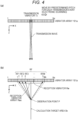
- FIGs. 7(a) and 7(b) the schematic diagrams for explaining the operation of the multiple reflection area extraction unit 106 in a case where a defect such as peeling or foreign matter to be inspected exists in the inspection object 300.
- a defect DF such as peeling, foreign matters, or voids to be inspected is often a layer defect parallel to the surface of the inspection object 300 in adhesion/joining of members or evaluation of quality of surface coating.
- the ultrasonic beam is transmitted from the vibrator array 101a of the probe 101 to the inspection object 300 including such a defect, as illustrated in Fig. 7(a) , the ultrasonic beam is incident substantially perpendicularly to the defect DF, so that the defect DF becomes a strong reflector. Then, a reflection wave having high intensity enters the vibrator array 101a, and multiple reflection that repeats reflection between the vibrator array 101a and the defect DF occurs.
- the tomographic image 300 RI based on the reflection wave from the inspection target range of the inspection object 300 is displayed in the real image area RIA, and the multiple reflection image MRI is displayed as a band-shaped high luminance area including a plurality of high luminance lines extending in the X direction arranged at a predetermined pitch in the depth direction in an area corresponding to a depth range deeper than the inspection target range of the inspection object and extending in the Z direction.
- a data portion in tomographic data which corresponds to a depth range deeper than the inspection target range of the inspection object 300 and in which the multiple reflection signal is mainly easily detected is defined as a multiple reflection area MRA (virtual image area VIA).
- Patent Literature 1 proposes a technique of removing noise due to multiple reflection echoes from a received ultrasonic signal by a filter as an object to be removed. That is, conventionally, it has been a technical common sense that artifacts due to multiple reflection are removed as noise that hinders inspection, for example, as described in Patent Literature 1.
- the specific time area designation unit 1061 designates, as the specific time area, a time area that is equal to or longer than the time in which the reflection wave from the inspection target range of the inspection object 300 reaches and has a predetermined length, specifies, as the multiple reflection area MRA, an area where image data based on the reflection signal obtained in the specific time area exists in the tomographic data, and mainly uses the signal from the multiple reflection area MRA as the analysis target signal for defect DF detection. Therefore, the specific time area may be set to be equal to or longer than the time when the ultrasonic wave reaches from the depth of the inspection target range of the inspection object 300.
- a value preset in the specific time area designation unit 1061 may be used as the specific time area.
- it may be configured such that the operator inputs the specific time area on the basis of the inspection target range of the inspection object 300 drawn in the real image area RIA.
- the luminance signal extraction unit 1062 extracts the luminance signal of the multiple reflection area MRA from the tomographic data and outputs the luminance signal to the detection unit 107.
- the detection unit 107 selects and analyzes the analysis target image data OL from the tomographic data of the multiple reflection area MRA, and detects the multiple reflection image MRI corresponding to the defect DL of the inspection object 300.
- the detection unit 107 includes an analysis target line specification unit 1071, a threshold setting unit 1072, and a determination unit 1073.
- Fig. 8(a) is a view schematically illustrating an example of a display image drawn on a display unit 111 in an embodiment of the scanning device 100 in a case where the defect DF of the inspection object 300 is not included
- Fig. 8(b) is a view schematically illustrating an example of a display image drawn on the display unit 111 in a case where the defect DF parallel to the surface is included in the inspection object 300.
- the operation of the detection unit 107 will be described using this display image.
- the analysis target line specification unit 1071 selects line data located at a predetermined depth ZP as the analysis target line OL from the tomographic data of the multiple reflection area MRA.
- a plurality of analysis target lines OL may be selected with different depths ZP.
- Threshold setting unit 1072 sets luminance threshold TH.
- the luminance threshold TH may be determined on the basis of, for example, the average luminance of the tomographic data of the multiple reflection area MRA.
- the determination unit 1073 determines and detects the data portion as the multiple reflection image MRI indicating the defect DF of the inspection object 300.
- the determination unit 1073 determines and detects the data portion as the multiple reflection image MRI indicating the defect DF of the inspection object 300.
- the analysis target line OL is selected from the multiple reflection area MRA located in the depth range deeper than the inspection target range of the inspection object 300, and the presence or absence of the multiple reflection image MRI indicating the defect DF of the inspection object 300 is detected. Therefore, as illustrated in Figs. 8(a) and 8(b) , the defect DF of the inspection object 300 can be detected without being affected by the strong specular reflection component (high luminance portion) in the surface reflection image SRI in the real image area RIA corresponding to the inspection target range of the shallow portion of the inspection object 300.
- the output control unit 108 includes a determination result display image generation unit 1081, and generates a display image indicating a determination result including, for example, an identification image indicating the presence or absence of the defect DF of the inspection object 300, character information, and the like, and outputs the display image to the display unit 111.
- Fig. 9 is a flowchart illustrating an operation of the ultrasonic scanning device 100.
- step S10 the number of transmission events 1 is initialized, transmission processing is performed to transmit an ultrasonic beam from the transmission vibrator Tx of the probe 101 (step S20), reception processing is performed to generate a reflection signal on the basis of the reflection wave received by the wave reception vibrator array (step S30), and phasing addition is performed on the reflection signal to generate an acoustic line signal (step S40).
- step S50 it is determined whether or not the number of transmission events I is the maximum value (step S50). In a case where the number of transmission events I is not the maximum value (step S50: No), I is incremented (step S60), the processing returns to step S20, and the transmission vibrator Tx is gradually moved to perform the processing of step S20 to S40. In a case where the number of transmission events I is the maximum value (step S50: Yes), the generation of the acoustic line signal of one frame is completed, and the processing proceeds to step S80.
- step S80 envelope detection, logarithmic compression, and coordinate transformation are performed on the acoustic line signal of one frame to generate tomographic data of one frame.
- the multiple reflection area MRA is specified from the tomographic data and the luminance signal is extracted (step S90), the depth ZP of the analysis target line is specified (step S100), the luminance threshold TH is set (step S 110), and the luminance signal of the analysis target line OL is extracted (step S120).
- step S 130 it is determined whether there is an area exceeding the luminance threshold of the predetermined length or more (step S 130). In a case where there is an area exceeding the luminance threshold of the predetermined length or more (step S130: Yes), it is determined that the multiple reflection image MRI is detected (step S140) and there is a defect DF (step S141). In a case where there is no area exceeding the luminance threshold of the predetermined length or more (step S 130: No), it is determined that the multiple reflection image MRI is not detected (step S150) and there is no defect DF (step S151), and the determination result is displayed on the display unit 111 (step S160), and the processing is ended.
- the inspection object 300 is, for example, a member having a layer structure in which thin plate-shaped members are laminated, such as CFRP
- defects such as peeling and foreign matters to be inspected are located in a shallow portion of the inspection object member in adhesion/bonding of members and evaluation of quality of surface coating.
- the shallow portion the influence of specular reflection components such as surface reflection having high signal intensity is strong, and the reflection wave from the defect is buried, so that there is a problem that the signal from the defect cannot be clearly specified, and it is difficult to accurately detect the defect.
- the inspection object is a defect such as interlayer adhesion/bonding failure in the thin plate material, peeling, foreign matters, or voids in the surface coating, a defect perpendicular to the incident direction becomes a strong reflector, and thus multiple reflection occurs, making it difficult to perform more accurate measurement.
- Patent Literature 1 it has been a technical common sense that the artifact due to multiple reflection is removed as noise that hinders inspection.
- the ultrasonic signal analysis device 160 is configured to extract, from the tomographic data, the multiple reflection area MRA that corresponds to the depth range deeper than the depth at which the real image of the inspection object 300 can be detected in the tomographic data and is mainly capable of detecting the multiple reflection signal, select and analyze the analysis target image data from the multiple reflection area MRA, and detect the multiple reflection image MRI corresponding to the defect DF of the inspection object 300.
- the analysis target line OL is selected from the multiple reflection area MRA located in the depth range deeper than the inspection target range of the inspection object 300, and the defect DF of the inspection object 300 can be detected without being affected by strong specular reflection components such as surface reflection in the real image area RIA corresponding to the inspection target range of the shallow portion of the inspection object 300.
- the real image area RIA has a stronger specular reflection component than the multiple reflection area MRA, and it is difficult to accurately detect the defect DF. Therefore, the defect DF detection in which the signal in the real image area RIA is set as an analysis target avoided, and the signal from the multiple reflection area MRA in which the multiple reflection is visualized is mainly set as an analysis target, whereby the defect located in the shallow portion of the inspection target member can be accurately detected even when the surface reflection is present.
- the analysis target image data is line data located at a predetermined depth, and in a case where there is a data portion exceeding the threshold luminance in a stepwise manner over a predetermined length or more in the line data, it is possible to select the analysis target line OL from the multiple reflection area MRA and detect the presence or absence of the multiple reflection image MRI indicating the defect DF of the inspection object 300 by adopting a configuration of determining the data portion as a multiple reflection image and detecting the data portion.
- the multiple reflection area MRA corresponding to the depth range deeper than the depth at which the real image of the inspection object 300 can be detected is specified, and the detection unit 107 extracts line data located at a predetermined depth from the multiple reflection area MRA as the analysis target image data, and when there is a data portion exceeding the threshold luminance TH in a stepwise manner over a predetermined length or more in the line data, the data portion is determined as the multiple reflection image MRI.
- the method of detecting the analysis target image data and the multiple reflection image MRI is not limited thereto.
- An ultrasonic scanning device 100A and its ultrasonic signal analysis device 160 according to the second embodiment differs from the first embodiment in that, planar cross-sectional image data in a planar direction of the inspection object corresponding to a specific depth included in the multiple reflection area MRA is selected as the analysis target image data, and for its spatial frequency, multiple reflection image MRI is detected by using principal component analysis (PCA).
- PCA principal component analysis
- the ultrasonic scanning device 100A according to the second embodiment is different from the ultrasonic scanning device 100 according to the first embodiment in that tomographic data to be generated is three-dimensional voxel data and in an analysis method for detecting a multiple reflection image MRI, and the other configurations are the same as those of the ultrasonic scanning device 100 illustrated in Fig. 1 . Therefore, generation of tomographic data and the method of detecting multiple reflection image MRI in the ultrasonic scanning device 100A will be outlined below, and description of other configurations will be omitted.
- Fig. 10 is a functional block diagram illustrating a configuration of each unit in the ultrasonic scanning device 100A.
- the transmission beamformer unit 103A and the reflection signal acquisition unit 104A include a 3D transmission unit 1031A and a 3D reception unit 1041A in place of the transmission unit 1031 and the reception unit 1041 in the scanning device 100, respectively.
- the transmission beamformer unit 103A and the reflection signal acquisition unit 104A repeatedly transmit and receive an ultrasonic wave for one frame while gradually moving the transmission vibrator Tx in the array direction for each transmission event to generate an acoustic line signal.
- the transmission beamformer unit 103A and the reflection signal acquisition unit 104A repeat transmission and reception for one frame while gradually moving the scanning plane in transmission and reception for one frame perpendicular to the arrangement direction of the vibrators 101a to generate acoustic line signals for a plurality of frames necessary for generation of three-dimensional tomographic data.
- the gradual movement of the scanning surface may be performed by an operator of gradually moving the probe 101 perpendicular to the arrangement direction of the vibrators 101a, or may be performed by electronic scanning using a 2D probe in which vibrators are arranged in a matrix.
- the tomographic data generation unit 105A acquires acoustic line signals for a plurality of frames, performs conversion to a luminance value by the envelope detection, logarithmic compression unit 1051A, and coordinate conversion to an orthogonal coordinate system by the coordinate conversion unit 1052A for each frame, generates tomographic data for one frame, repeats this processing for a plurality of frames, generates three-dimensional tomographic data, and outputs the three-dimensional tomographic data to the multiple reflection area extraction unit 106A.
- the multiple reflection area extraction unit 106A includes a specific time area designation unit 1061A and a luminance signal extraction unit 1062A.
- the specific time area designation unit 1061A extracts the multiple reflection area, which corresponds to the depth range deeper than the depth at which the real image of the inspection object can be detected in the acquired three-dimensional 3D tomographic data and in which the multiple reflection signal can be mainly detected, as the data area that can be the analysis target from the 3D tomographic data.
- the specification of the depth range is performed by designating, as the specific time area, a time area that is equal to or longer than the time in which the reflection wave from the inspection target range of the inspection object arrives and has a predetermined length.
- the second embodiment is different from the configuration according to the first embodiment in that the multiple reflection area to be extracted is three-dimensional voxel data in the X-Y-Z direction.
- the luminance signal extraction unit 1062A extracts the luminance signal of the multiple reflection area MRA from the 3D tomographic data and outputs the luminance signal to the detection unit 107A.
- the detection unit 107 selects the analysis target image data OL from the 3D tomographic data of the multiple reflection area MRA, analyzes the extracted spatial frequency by principal component analysis, and selects one or more principal components including a principal component that reacts to the spatial frequency component of the multiple reflection image MRI corresponding to the defect DL of the inspection object 300.
- the detection unit 107A includes an analysis target line specification unit 1071A, a spatial frequency component conversion unit 1072A, a principal component analysis unit 1073A, and a principal component selection unit 1074A.
- Figs. 11(a) and 11(b) are views schematically illustrating an example of a display image drawn on the display unit 111 in the embodiment of the ultrasonic scanning device 100A. The operation of the detection unit 107A will be described using this display image.
- an X direction represents an arrangement direction of the vibrators 101a
- a Y direction represents a direction perpendicular to the arrangement direction of the vibrators 101a
- a Z direction represents a depth direction.
- the analysis target image data OL is planar cross-sectional image data in a planar direction of the inspection object corresponding to the specific depth ZP.
- the analysis target line specification unit 1071A selects cross-sectional image data in the planar direction of the inspection object located at the predetermined depth ZP as the analysis target planar cross-section OF from the 3D tomographic data of the multiple reflection area MRA.
- a plurality of the analysis target planar cross-sections OF may be selected by varying the depth ZP.
- the spatial frequency component conversion unit 1072A converts the data of the analysis target planar cross-section OF into a set of a plurality of line data (in the embodiment, Y pieces of line data in the X direction are used) in the X or Y direction, and extracts a spatial frequency component for the set of line data.
- the principal component analysis unit 1073A calculates a first principal component to an M-th principal component with M as a natural number for the spatial frequency component.
- V 1 N ⁇ 1 X T X
- ⁇ is calculated as the eigenvalue of the covariance matrix V
- the coupling coefficient w1 of the first principal component z1 is calculated as the eigenvector corresponding to the maximum eigenvalue of the covariance matrix V
- the coupling coefficient w M of the M-th principal component z M is calculated as an eigenvector corresponding to the M-th largest eigenvalue of the covariance matrix V
- a principal component (hereinafter, it may be referred to as a "multiple reflection image corresponding principal component”) that reacts to the multiple reflection image MRI corresponding to the defect DL appears, for example, in the first principal component, and a principal component (hereinafter, it may be referred to as a “multiple reflection image non-corresponding principal component”) that does not react to the multiple reflection image MRI corresponding to the defect DL appears, for example, in the second principal component in some cases, but the present invention is not limited thereto, and the principal component may appear in principal components other than the first and second principal components.
- the principal component selection unit 1074A selects one principal component (multiple reflection image corresponding principal component) including the multiple reflection image corresponding principal component reactive to the spatial frequency component of the multiple reflection image MRI corresponding to the defect DL of the inspection object from the calculated first principal component to the M-th principal component, and outputs the selected principal component to the output control unit 108A.
- a plurality of principal components including at least one multiple reflection image corresponding principal component may be selected as the selected principal component.
- all the principal components from the first principal component to the M-th principal component may be selected.
- the principal component to be selected may be set in advance according to the inspection target, or may be arbitrarily set.
- the output control unit 108A includes a reconstruction/output unit 1081A.
- the reconstruction/output unit 1081A reconstructs the analysis target image data OL for the selected principal component. Specifically, by using the principal component score and the coupling coefficient (eigenvector) obtained by the principal component analysis unit 1073A, the analysis target image data OL (in the embodiment, the analysis target planar cross-section OF) is reconstructed in the principal component direction selected by the principal component selection unit 1074A, and an image is generated and output to the display unit 111.
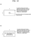
- Figs. 12(a) and 12(b) are views schematically illustrating an example of a display image drawn on the display unit 111 in the embodiment of the ultrasonic scanning device 100A.
- a display result by the output control unit 108A will be described using this display image.
- the intensity distribution of the principal component representing the characteristic of the spatial frequency component of the multiple reflection image MRI is displayed on the analysis target planar cross-section OF, and the intensity and position of the multiple reflection image MRI are displayed as the intensity distribution of the multiple reflection image corresponding principal component.
- the multiple reflection image MRI is not displayed on the analysis target planar cross-section OF.
- the viewer can easily grasp the position of the defect DF of the inspection object 300 through the display image.
- Fig. 13 is a flowchart illustrating an operation of the ultrasonic scanning device 100A.
- the same processing as those in the operation of the ultrasonic scanning device 100 are denoted by the same reference signs as those in Fig. 9 , and the description thereof is omitted.
- transmission and reception for one frame are repeated while the scan plane in transmission and reception for one frame is gradually moved perpendicularly to the arrangement direction of the vibrators 101a, thereby generating three-dimensional tomographic data.
- step S85A it is determined whether or not the position Y of the scanning plane in the direction perpendicular to the arrangement direction of the vibrators 10 1a in transmission and reception for one frame is the maximum value.
- step S85A the processing returns to step S10 by incrementing Y (step S86A), and the processing of steps S10 to S90 is performed by gradually moving the scanning plane in the direction perpendicular to the arrangement direction.
- step S85: Yes generation of three-dimensional tomographic data is completed, and the processing proceeds to step S90A.
- the multiple reflection area MRA is specified from the three-dimensional tomographic data and the luminance signal is extracted (step S90A), the depth ZP of the analysis target planar cross-section OF is specified (step S200A), a set of a plurality of pieces of line data (X pieces) is acquired (step S210A), and the spatial frequency component of the set of line data is extracted and converted into the data set of the spatial frequency (step S230A).
- the principal component analysis is performed on the spatial frequency component (step S240A), one or more principal components including the principal component (multiple reflection image corresponding principal component) reacting with the spatial frequency component of the multiple reflection image MRI corresponding to the defect DL of the inspection object 300 are selected (step S250A), the data of the analysis target planar cross-section OF is reconstructed in the direction of the selected principal component (step S260A), the image data in the direction of the principal component is generated (step S270A), the image is displayed on the display unit 111 (step S300), and the processing is ended.
- one or more principal components including the principal component (multiple reflection image corresponding principal component) reacting with the spatial frequency component of the multiple reflection image MRI corresponding to the defect DL of the inspection object 300 are selected (step S250A)
- the data of the analysis target planar cross-section OF is reconstructed in the direction of the selected principal component
- step S270A the image data in the direction of the principal component is generated
- the image is displayed on the display unit 111 (step S300
- the analysis target data is the planar cross-section OF data in the plane direction of the inspection object corresponding to a specific depth
- the detection unit 107A extracts the spatial frequency of the planar cross-section OF data, selects one or more principal components including a principal component (multiple reflection image corresponding principal component) that reacts to a spatial frequency component of a multiple reflection image corresponding to a defect of the inspection object in the analysis target data by the principal component analysis, and reconstructs the planar cross-section OF data in the direction of the selected principal component to generate the principal component direction cross-sectional image data.
- a principal component multiple reflection image corresponding principal component
- the analysis target planar cross-sectional image OF is selected from the multiple reflection area MRA located in the depth range deeper than the inspection target range of the inspection object 300, the intensity distribution in the principal component direction that reacts to the characteristic of the spatial frequency component of the multiple reflection image MRI corresponding to the defect DF of the inspection object is displayed on the analysis target planar cross-section OF, and the intensity and position of the multiple reflection image MRI are displayed as the intensity distribution of the principal component.
- data of a solid portion corresponding to a specific depth range included in the multiple reflection area MRA is selected as analysis target data, and the multiple reflection image MRI is detected using the principal component analysis for the spatial frequency.
- data converted into a luminance value after envelope detection is set as an analysis target.
- an ultrasonic scanning device 100B differs from the second embodiment in that data of a solid portion corresponding to a specific depth range ZP1 (hereinafter, the depth direction may be referred to as a Z direction) included in the multiple reflection area MRA is selected as the analysis target data, and the frequency (obtained by frequency converting a signal in the Z direction) is detected by multiple reflection image MRI using principal component analysis.
- the third embodiment also differs from the second embodiment in that data before envelope detection including a phase to be subjected to FFT analysis, that is, data before conversion into a luminance value is set as an analysis target. According to the method, even when there is surface reflection, it is possible to more accurately detect a defect included in the predetermined depth range ZP1 of the inspection target member.
- the ultrasonic scanning device 100B according to the third embodiment is different from the ultrasonic scanning device 100A according to the second embodiment in an analysis method for detecting a multiple reflection image MRI, and the other configurations are the same as those of the ultrasonic scanning device 100A illustrated in Fig. 10 . Therefore, the method of detecting multiple reflection image MRI in the ultrasonic scanning device 100A will be outlined below, and description of other configurations will be omitted.
- Fig. 14 is a functional block diagram illustrating a configuration of each unit in the ultrasonic scanning device 100B.
- the multiple reflection area extraction unit 106A extracts the signal of the multiple reflection area MRA from the 3D tomographic data on the basis of the acoustic line signals for a plurality of frames necessary for generating the three-dimensional tomographic data supplied from the reflection signal acquisition unit 104A, and outputs the signal to the detection unit 107B.
- FFT analysis is performed on the acoustic line signal before envelope detection as an analysis target.
- the detection unit 107B selects the analysis target solid portion OS from the 3D tomographic data of the multiple reflection area MRA, converts a signal extracted from the data of the solid portion OS into a frequency by FFT, and performs principal component analysis, thereby selecting one or more principal components including a principal component reacting with a frequency component of the multiple reflection image MRI corresponding to the defect DL of the inspection object 300.
- the detection unit 107B includes an analysis target solid portion specification unit 1071B, an FFT analysis unit 1072B, a principal component analysis unit 1073B, and a principal component selection unit 1074B.
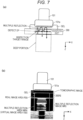
- Fig. 15 is a schematic diagram for explaining the operation of the ultrasonic scanning device 100B.
- an X direction represents an arrangement direction of the vibrators 101a
- a Y direction represents a direction perpendicular to the arrangement direction of the vibrators 101a
- a Z direction represents a depth direction.
- the analysis target data is data of the solid portion OS corresponding to the specific depth range ZP1.
- the analysis target solid portion specification unit 1071B selects a solid portion located in the predetermined depth range ZP1 as the analysis target solid portion OS from the data of the multiple reflection area MRA.
- the FFT analysis unit 1072B performs FFT analysis (Fast Fourier Transform; FFT) on the data of the analysis target solid portion OS for the data on the line data in the Z direction passing through the position P (Xn, Yn), extracts a frequency component for the line data, repeats the FFT analysis while making the position P (Xn, Yn) different, and extracts a frequency component for all the data in the analysis target solid portion OS.
- FFT Fast Fourier Transform
- the principal component analysis unit 1073B performs principal component analysis on the obtained frequency component, and calculates a first principal component to an M-th principal component (M is a natural number).
- the principal component selection unit 1074B selects one principal component (multiple reflection image corresponding principal component) including the multiple reflection image corresponding principal component reactive to the spatial frequency component of the multiple reflection image MRI corresponding to the defect DL of the inspection object from the calculated first principal component to the M-th principal component, and outputs the selected principal component to the output control unit 108A.
- a plurality of principal components including at least one multiple reflection image corresponding principal component may be selected as the selected principal component.
- all the principal components from the first principal component to the M-th principal component may be selected.
- the principal component to be selected may be set in advance according to the inspection target, or may be arbitrarily set.
- the output control unit 108 includes a reconstruction/output unit 1081B.
- the reconstruction/output unit 1081B reconstructs the analysis target image data OL for the selected principal component. Specifically, by using the principal component score and the coupling coefficient (eigenvector) obtained by the principal component analysis unit 1073B, the analysis target image data OL (in the embodiment, the analysis target solid portion OS) is reconstructed in the principal component direction selected by the principal component selection unit 1074B, and an image is generated and output to the display unit 111.
- Fig. 16 is a flowchart illustrating an operation of the ultrasonic scanning device 100B.
- the same processing as those in the operation of the ultrasonic scanning device 100A are denoted by the same reference signs as those in Fig. 13 , and the description thereof is omitted.
- steps S10 to 60, S85A, and 86A acoustic line signals for a plurality of frames necessary for generating three-dimensional tomographic data are generated, and in step S90A, the multiple reflection area MRA is specified from the generated three-dimensional tomographic data and a signal is extracted.
- step S300B a set of a plurality of pieces of line data (X ⁇ Y pieces) is acquired (step S310B), the set of line data is subjected to FFT analysis to extract a frequency component, and the frequency component is converted into a data set of frequency (step S330B).
- the principal component analysis is performed on the frequency component (step S340B), one or more principal components including the principal component (multiple reflection image corresponding principal component) reacting with the frequency component of the multiple reflection image MRI corresponding to the defect DL of the inspection object 300 are selected (step S350B), the data of the analysis target solid portion OS is reconstructed in the direction of the selected principal component (step S360B), the principal component direction image data is generated (step S370B), the image is displayed on the display unit 111 (step S400B), and the processing is ended.
- one or more principal components including the principal component (multiple reflection image corresponding principal component) reacting with the frequency component of the multiple reflection image MRI corresponding to the defect DL of the inspection object 300 are selected (step S350B)
- the data of the analysis target solid portion OS is reconstructed in the direction of the selected principal component
- step S370B the principal component direction image data is generated
- the image is displayed on the display unit 111 (step S400B)
- the processing is ended.
- the ultrasonic signal analysis device 160 included in the ultrasonic scanning device 100B according to the third embodiment adopts a configuration in which the analysis target data is data of a solid portion corresponding to a specific depth range ZP1, the detection unit 107B performs fast Fourier transform and frequency transform on the analysis target data for each unit data corresponding to the spatial position P (Xn, Yn), selects one or more principal components including a principal component (multiple reflection image corresponding principal component) reactive to a frequency component of a multiple reflection image corresponding to the defect DF of the inspection object in the analysis target data by principal component analysis, and the output control unit 108B reconstructs the analysis target data in a direction of the selected principal component to generate the principal component direction image data.
- the analysis target data is data of a solid portion corresponding to a specific depth range ZP1
- the detection unit 107B performs fast Fourier transform and frequency transform on the analysis target data for each unit data corresponding to the spatial position P (Xn, Yn)
- the analysis target solid portion OS is selected from the multiple reflection area MRA located in the depth range deeper than the inspection target range of the inspection object 300, the intensity distribution in the principal component direction that reacts to the characteristic of the frequency component of the multiple reflection image MRI corresponding to the defect DF of the inspection object is displayed on the analysis target solid portion OS, and the intensity and position of the multiple reflection image MRI are displayed as the intensity distribution of the multiple reflection image corresponding principal component.
- the embodiments of the present disclosure are implemented as an ultrasonic signal analysis system 1 that collects and analyzes tomographic data from an ultrasonic scanning device 100 via a network.
- an ultrasonic signal analysis system 1 according to the embodiments will be described in detail with reference to the drawings.
- Fig. 1 is a schematic configuration diagram of an ultrasonic signal analysis system 1. As illustrated in Fig. 17 , the ultrasonic signal analysis system 1 includes a plurality of ultrasonic scanning devices 100, a tomographic data storage device 30, and an ultrasonic signal analysis device 160 connected to a communication network N.
- the communication network N is, for example, the Internet, and the plurality of ultrasonic scanning devices 100, the tomographic data storage device 30, and the ultrasonic signal analysis device 160 are connected so as to be able to exchange information with each other.
- the ultrasonic scanning device 100 acquires tomographic data of the inspection object via the connected probe 101 and supplies the tomographic data via the communication network N.
- the ultrasonic scanning device 100 may be configured to function as a tomographic data generation device in which only the transmission beamformer unit 103, the multiplexer 102, the reflection signal acquisition unit 104, and the tomographic data generation unit 105 are operated without using the function of the ultrasonic signal analysis device 160 among the functional blocks illustrated in Fig. 1 .
- the tomographic data storage device 30 is, for example, a computer-readable recording medium such as a hard disk, and acquires and stores tomographic data supplied from the ultrasonic scanning device 100.
- the ultrasonic signal analysis device 160 includes the multiple reflection area extraction unit 106, the detection unit 107, and the output control unit 108, reads tomographic data stored in the tomographic data storage device 30, or receives supply of tomographic data from the ultrasonic scanning device 100, detects a multiple reflection image MRI in the tomographic data by the analysis method according to any one of the first to third embodiments, thereby detecting a defect DF in an inspection target member, and outputs a detection result to the display unit 111 to display the detection result. Furthermore, the ultrasonic signal analysis device 160 outputs the detection result to the ultrasonic signal analysis device 160 via the communication network N and stores the detection result.
- the tomographic data acquired by the plurality of ultrasonic scanning devices 100 can be supplied to the ultrasonic signal analysis device 160 via the communication network N to detect the defect located in the shallow portion of the inspection target member.
- ultrasonic transmission may be performed from all the vibrators 101a existing in the probe 101. Reflected ultrasonic waves can be received from the entire ultrasonic irradiation area Ax by one ultrasonic wave transmission without repeating the ultrasonic wave transmission.
- the calculation target area Bx is a linear area that passes through the array center of the reception aperture Rx, is perpendicular to the vibrator array, and has a single vibrator width.
- the calculation target area Bx is not limited thereto, and may be set to an arbitrary area included in the ultrasonic irradiation area Ax.
- a band-shaped rectangular area having a plurality of vibrator widths with a center line being a straight line passing through the array center of the reception vibrator and perpendicular to the vibrator array may be used.
- a hourglass-shaped area may be used.
- the calculation target area Bx set for each transmission event may be set to overlap in the vibrator array direction. The S/N ratio of the ultrasound image generated by synthesizing the acoustic line signals of the overlapping areas by the synthetic aperture method can be improved.
- the probe has a probe configuration in which a plurality of piezoelectric elements is arranged in a one-dimensional direction.
- the configuration of the probe is not limited to this, and for example, a two-dimensional array vibrator in which a plurality of piezoelectric conversion elements is arranged in a two-dimensional direction or a swing type probe in which a plurality of vibrators arranged in a one-dimensional direction is mechanically swung to acquire three-dimensional tomographic data may be used, and the probe can be appropriately used according to the measurement.
- the irradiation position and direction of the ultrasonic beam to be transmitted can be controlled by individually changing the timing of applying a voltage to the piezoelectric conversion element and the value of the voltage.
- the probe and the display unit are connected from the outside.
- the probe and the display unit may be integrally provided in the ultrasonic scanning device.
- the reception beamforming processing is performed in synchronization with the transmission of the ultrasonic wave, but the present invention is not limited to this case.
- the aspect of the present disclosure may be applied in the synthetic aperture method, and phasing addition may be performed after a plurality of times of ultrasonic wave transmission/reception for one frame is completed.
- each operation other than the calculation of the reception time is not limited to the above case, and arbitrary control may be performed.
- one aspect of the present disclosure has been described on the basis of the above-described embodiments, one aspect of the present disclosure is not limited to the above-described first embodiment, and the following case is also included in one aspect of the present disclosure.
- one aspect of the present disclosure may be a computer system including a microprocessor and a memory, in which the memory stores the computer program, and the microprocessor operates according to the computer program.
- the memory stores the computer program
- the microprocessor operates according to the computer program.
- it may be a computer system that has a computer program of the ultrasonic signal processing method of the present invention and operates according to this program (or instructs each connected part to operate).
- the present invention also includes a case where all or a part of the ultrasonic scanning device and all or a part of the ultrasonic signal processing device are configured by a computer system including a microprocessor, a recording medium such as a ROM and a RAM, a hard disk unit, and the like.
- the RAM or the hard disk unit stores a computer program for achieving the same operation as each of the above devices.
- the microprocessor operates in accordance with the computer program, whereby each device achieves its function.
- the system LSI is a super multifunctional LSI manufactured by integrating a plurality of components on one chip, and is specifically a computer system including a microprocessor, a ROM, a RAM, and the like. These may be individually integrated into one chip, or may be integrated into one chip so as to include a part or all of them.
- the LSI may be referred to as an IC, a system LSI, a super LSI, or an ultra LSI depending on the degree of integration.
- the RAM stores a computer program for achieving the same operation as each of the above devices.
- the microprocessor operates in accordance with the computer program, whereby the system LSI achieves its function.
- the system LSI achieves its function.
- the beamforming method of the present invention is stored as an LSI program
- the LSI is inserted into a computer, and a predetermined program (beamforming method) is executed is also included in the present invention.
- the circuit integration method is not limited to LSI, and may be realized by a dedicated circuit or a general-purpose processor.
- An FPGA Field Programmable Gate Array
- a reconfigurable processor Reconfigurable Processor in which connections and settings of circuit cells inside the LSI can be reconfigured may be used.
- the functional blocks may be integrated using the technology.
- the functions of the ultrasonic scanning device according to each first embodiment may be realized by a processor such as a CPU executing a program.
- a non-transitory computer-readable recording medium in which a program for performing a scanning method of the ultrasonic scanning device or a beamforming method is recorded may be used.
- the program or signal may be recorded on a recording medium and transferred, so that the program may be implemented by another independent computer system.
- the program can be distributed via a transmission medium such as the Internet.
- the data storage unit which is a storage device is included in the ultrasonic scanning device, but the storage device is not limited thereto, and a semiconductor memory, a hard disk drive, an optical disk drive, a magnetic storage device, or the like may be connected to the ultrasonic scanning device from the outside.
- the division of the functional blocks in the block diagram is an example, and a plurality of functional blocks may be realized as one functional block, one functional block may be divided into a plurality of functional blocks, or some functions may be transferred to another functional block.
- functions of a plurality of functional blocks having similar functions may be processed in parallel or in a time division manner by single hardware or software.
- the order in which the above steps are executed is for specifically describing the present invention, and may be an order other than the above order.
- some of the above steps may be executed simultaneously (in parallel) with other steps.
- the present invention also includes various modifications in which changes within a range easily conceived by those skilled in the art are made to the present embodiments.
- a wave motion analysis device is a wave motion analysis device that detects a defect of an inspection object on the basis of a reflection wave obtained from the inspection object, the wave motion analysis device including: a multiple reflection area extraction unit that acquires tomographic data generated on the basis of the reflection wave and extracts a multiple reflection area from the tomographic data; and a detection unit that detects a multiple reflection image corresponding to the defect of the inspection object from the extracted multiple reflection area.
- the multiple reflection area may correspond to a depth range deeper than a depth at which a real image of the inspection object can be detected in the tomographic data, and may be an area in which a multiple reflection signal can be mainly detected.
- the detection unit may be configured to select line data located at a predetermined depth from the multiple reflection area, and in a case where there is a data portion exceeding a threshold luminance in a stepwise manner over a predetermined length or more in the line data, determine the data portion as the multiple reflection image and detect the data portion.
- the multiple reflection area extraction unit may be configured to extract the multiple reflection area on the basis of a preset parameter.
- the multiple reflection area extraction unit may be configured to extract the multiple reflection area by determining signal attenuation or the like.
- the multiple reflection area extraction unit may be configured to extract data of a time-series luminance signals in the multiple reflection area and generate a signal train to be analyzed.
- the multiple reflection area extraction unit may be configured to calculate an average value of luminance signals in the multiple reflection area to generate a signal train to be analyzed.
- the multiple reflection area extraction unit may be configured to calculate a maximum value of a luminance signal in the multiple reflection area to generate a signal train to be analyzed.
- the detection unit selects, from the multiple reflection area, planar cross-sectional data in a planar direction of the inspection object corresponding to a specific depth, extracts a spatial frequency of the planar cross-sectional data, and selects one or more principal components including a principal component that reacts to a spatial frequency component of a multiple reflection image corresponding to a defect of the inspection object in the planar cross-sectional data by principal component analysis. Further, it may be configured to include a reconstruction/output unit, and reconstruct the planar cross-sectional data in the selected principal component direction to generate cross-sectional image data in the principal component direction.
- the detection unit selects data of a solid portion corresponding to a specific depth range from the multiple reflection area, performs fast Fourier transform on the data of the solid portion for each unit data corresponding to a spatial position to perform frequency conversion, and selects one or more principal components including a principal component that reacts to a frequency component of a multiple reflection image corresponding to a defect of the inspection object in the data of the solid portion by principal component analysis. Further, it may be configured to include a reconstruction/output unit, and reconstruct the data of the solid portion in the selected principal component direction to generate the principal component direction image data.
- the output control unit may be configured to generate first principal component direction 3D image data obtained by reconstructing the analysis target image data in the first principal component direction and second principal component direction 3D image data obtained by reconstructing the analysis target image data in the second principal component direction.
- one aspect of the present disclosure may be a scanning device including: the wave motion analysis device according to any one of the above aspects; a reflection signal acquisition unit that acquires a reflection signal based on a reflection wave obtained from the inspection object on the basis of a wave motion from a probe; and a tomographic data generation unit that generates tomographic data on the basis of the reflection signal and supplies the tomographic data to the multiple reflection area extraction unit.
- the tomographic data generation unit may be a scanning device that generates the tomographic data by converting the reflection signal into luminance data.
- a plurality of principal components can be specified, and the multiple reflection image corresponding area and the multiple reflection non-corresponding area can be specified from among the plurality of principal components.
- the tomographic data generation unit may be a scanning device that logarithmically compresses the reflection signal and converts the reflection signal into the luminance data.
- the resolution in the low luminance portion can be improved, and the level of analysis accuracy can be made uniform from low luminance to high luminance.
- one aspect of the present disclosure may be a wave motion analysis system including the wave motion analysis device according to any one of the above aspects and a tomographic data generation device that generates tomographic data on the basis of a reflection wave obtained from an inspection object.
- the tomographic data acquired by the plurality of scanning devices can be supplied to the wave motion signal analysis device via the communication network N to detect the defect located at the shallow portion of the inspection target member.
- a wave motion analysis system may be a wave motion analysis system including the wave motion analysis device according to any one of the above aspects and a tomographic data generation device that generates a wave motion using a probe, acquires a reflection signal based on a reflection wave obtained from an inspection object, and generates tomographic data on the basis of the reflection signal.
- the tomographic data acquired by the plurality of scanning devices can be supplied to the wave motion signal analysis device via the communication network N to detect the defect located at the shallow portion of the inspection target member.
- one aspect of the present disclosure may be a wave motion analysis method for detecting a defect of an inspection object on the basis of a reflection wave obtained from the inspection object, the method including: acquiring tomographic data generated on the basis of the reflection wave; extracting, from the tomographic data, a multiple reflection area that corresponds to a depth range deeper than a depth at which a real image of the inspection object can be detected in the tomographic data and in which multiple reflection signals can be mainly detected; and detecting a multiple reflection image corresponding to the defect of the inspection object from the extracted multiple reflection area.
- one aspect of the present disclosure may be a program that causes a computer to perform a wave motion analysis processing of detecting a defect of an inspection object on the basis of a reflection wave obtained from the inspection object, the wave motion analysis processing including: acquiring tomographic data generated on the basis of the reflection wave; extracting, from the tomographic data, a multiple reflection area that corresponds to a depth range deeper than a depth at which a real image of the inspection object can be detected in the tomographic data and in which multiple reflection signals can be mainly detected; and detecting a multiple reflection image corresponding to the defect of the inspection object from the extracted multiple reflection area.
- the wave motion signal analysis processing program capable of acquiring the tomographic data acquired by the scanning device and detecting the defect located in the shallow portion of the inspection target member.
- the wave motion analysis device, the wave motion analysis system, the scanning device, the wave motion analysis method, and the program according to the present disclosure can be widely utilized for non-destructive inspection for defect detection using a probe including a vibrator array.
Landscapes
- Physics & Mathematics (AREA)
- General Physics & Mathematics (AREA)
- Health & Medical Sciences (AREA)
- Life Sciences & Earth Sciences (AREA)
- Chemical & Material Sciences (AREA)
- Analytical Chemistry (AREA)
- Biochemistry (AREA)
- General Health & Medical Sciences (AREA)
- Immunology (AREA)
- Pathology (AREA)
- Engineering & Computer Science (AREA)
- Acoustics & Sound (AREA)
- Signal Processing (AREA)
- Theoretical Computer Science (AREA)
- Mathematical Physics (AREA)
- Quality & Reliability (AREA)
- Computer Vision & Pattern Recognition (AREA)
- Spectroscopy & Molecular Physics (AREA)
- Investigating Or Analyzing Materials By The Use Of Ultrasonic Waves (AREA)
- Algebra (AREA)
- Mathematical Analysis (AREA)
- Mathematical Optimization (AREA)
- Pure & Applied Mathematics (AREA)
Applications Claiming Priority (2)
| Application Number | Priority Date | Filing Date | Title |
|---|---|---|---|
| JP2021097541 | 2021-06-10 | ||
| PCT/JP2022/014463 WO2022259710A1 (ja) | 2021-06-10 | 2022-03-25 | 波動解析装置、探傷装置、波動解析システム、波動解析方法および、プログラム |
Publications (3)
| Publication Number | Publication Date |
|---|---|
| EP4354133A1 true EP4354133A1 (de) | 2024-04-17 |
| EP4354133A4 EP4354133A4 (de) | 2024-12-04 |
| EP4354133B1 EP4354133B1 (de) | 2026-02-04 |
Family
ID=84425218
Family Applications (1)
| Application Number | Title | Priority Date | Filing Date |
|---|---|---|---|
| EP22819899.0A Active EP4354133B1 (de) | 2021-06-10 | 2022-03-25 | Wellenbewegungsanalysevorrichtung, abtastvorrichtung, wellenbewegungsanalysesystem, wellenbewegungsanalyseverfahren und programm |
Country Status (4)
| Country | Link |
|---|---|
| US (1) | US20240273701A1 (de) |
| EP (1) | EP4354133B1 (de) |
| JP (1) | JP7732506B2 (de) |
| WO (1) | WO2022259710A1 (de) |
Families Citing this family (3)
| Publication number | Priority date | Publication date | Assignee | Title |
|---|---|---|---|---|
| JPWO2024166770A1 (de) * | 2023-02-08 | 2024-08-15 | ||
| CN118347971B (zh) * | 2024-06-18 | 2024-08-23 | 石家庄康力药业有限公司 | 一种片剂的成品质量检测方法及检测系统 |
| CN119985356B (zh) * | 2025-04-15 | 2025-08-05 | 山东宏泰电器有限公司 | 医用冰箱箱体制造检测系统及方法 |
Family Cites Families (14)
| Publication number | Priority date | Publication date | Assignee | Title |
|---|---|---|---|---|
| JPH01170850A (ja) * | 1987-12-26 | 1989-07-05 | Nkk Corp | 部材の材質境界面検査方法 |
| JPH0587781A (ja) * | 1991-09-30 | 1993-04-06 | Kobe Steel Ltd | 積層材の超音波探傷方法 |
| JPH05333000A (ja) * | 1992-05-28 | 1993-12-17 | Nippon Steel Corp | 超音波探傷装置 |
| JPH11326287A (ja) * | 1998-05-15 | 1999-11-26 | Nippon Krautkraemer Ferusutaa Kk | 超音波探傷装置を用いた溶接部の溶融凝固部分の判定法 |
| JP2001208527A (ja) * | 1999-11-15 | 2001-08-03 | Just | 炭素繊維被覆層の測定方法 |
| JP5311766B2 (ja) * | 2007-06-13 | 2013-10-09 | 三菱電機株式会社 | 境界面検査装置及び境界面検査方法 |
| JP5210087B2 (ja) * | 2008-08-14 | 2013-06-12 | 富士フイルム株式会社 | 光超音波断層画像化装置 |
| JP2010175519A (ja) | 2009-02-02 | 2010-08-12 | Kansai Electric Power Co Inc:The | 超音波検査装置 |
| JP5735706B2 (ja) * | 2012-04-24 | 2015-06-17 | 非破壊検査株式会社 | 積層体の剥離検査方法及び剥離検査装置 |
| JP6652281B2 (ja) * | 2015-01-09 | 2020-02-19 | キヤノン株式会社 | 光断層撮像装置、その制御方法、及びプログラム |
| BR112018009718B1 (pt) * | 2015-11-27 | 2023-05-09 | Jfe Steel Corporation | Método e aparelho para medir craqueamento induzido por hidrogênio |
| US11353430B2 (en) * | 2017-03-13 | 2022-06-07 | Baker Hughes Oilfield Operations Llc | Phased array probe and method for testing a spot-weld |
| JP7354632B2 (ja) * | 2019-07-12 | 2023-10-03 | コニカミノルタ株式会社 | 超音波診断装置、および、超音波診断装置の制御方法 |
| US12146952B2 (en) * | 2019-09-30 | 2024-11-19 | Evident Canada, Inc. | Method and system for generating a merged B-scan for assisted ultrasonic inspection flaw screening |
-
2022
- 2022-03-25 US US18/566,444 patent/US20240273701A1/en active Pending
- 2022-03-25 WO PCT/JP2022/014463 patent/WO2022259710A1/ja not_active Ceased
- 2022-03-25 JP JP2023527530A patent/JP7732506B2/ja active Active
- 2022-03-25 EP EP22819899.0A patent/EP4354133B1/de active Active
Also Published As
| Publication number | Publication date |
|---|---|
| JP7732506B2 (ja) | 2025-09-02 |
| US20240273701A1 (en) | 2024-08-15 |
| EP4354133B1 (de) | 2026-02-04 |
| JPWO2022259710A1 (de) | 2022-12-15 |
| EP4354133A4 (de) | 2024-12-04 |
| WO2022259710A1 (ja) | 2022-12-15 |
Similar Documents
| Publication | Publication Date | Title |
|---|---|---|
| EP4354133A1 (de) | Wellenbewegungsanalysevorrichtung, abtastvorrichtung, wellenbewegungsanalysesystem, wellenbewegungsanalyseverfahren und programm | |
| Wilcox et al. | Advanced reflector characterization with ultrasonic phased arrays in NDE applications | |
| Chaffaı et al. | Frequency dependence of ultrasonic backscattering in cancellous bone: Autocorrelation model and experimental results | |
| EP0168565B1 (de) | Verfahren zur Ultraschallmessung und dazugehöriges Gerät | |
| McKee et al. | Volumetric imaging through a doubly-curved surface using a 2D phased array | |
| US9207639B2 (en) | Transforming A-scan data samples into a three-dimensional space for facilitating visualization of flaws | |
| Brizuela et al. | Improving elevation resolution in phased-array inspections for NDT | |
| Gauthier et al. | Lightweight and amplitude-free ultrasonic imaging using single-bit digitization and instantaneous phase coherence | |
| EP2315020A1 (de) | Verfahren zur abbildung von strukturdefekten, vorrichtung zur abbildung von strukturdefekten, verfahren zur abbildung einer blase oder läsion und vorrichtung zur abbildung einer blase oder läsion | |
| US20120065504A1 (en) | Method for measuring the viscoelastic properties of biological tissue employing an ultrasonic transducer | |
| EP1691194B1 (de) | Verfahren und System für Ultraschalluntersuchung | |
| WO2014167698A1 (ja) | 超音波検査方法および装置 | |
| Mayer et al. | Characterization of reflector types by phase-sensitive ultrasonic data processing and imaging | |
| Shi et al. | Resolution enhancement of ultrasonic imaging at oblique incidence by using WTFM based on FMC-AR | |
| Wolf et al. | Improved failure analysis in scanning acoustic microscopy via advanced signal processing techniques | |
| Gauthier et al. | Ultrasonic multi-view data merging using the vector coherence factor | |
| Jin et al. | Profile reconstruction of irregular planar defects by mirrored composite-mode total focusing method | |
| Sanabria et al. | Calculation of volumetric sound field of pulsed air-coupled ultrasound transducers based on single-plane measurements | |
| Wilcox et al. | Exploiting the Full Data Set from Ultrasonic Arrays by Post‐Processing | |
| Lasaygues et al. | Contrast resolution enhancement of Ultrasonic Computed Tomography using a wavelet-based method–Preliminary results in bone imaging | |
| Ramanan et al. | Quantitative non-destructive evaluation of cfrp components by sampling phased array | |
| Cario et al. | Identifying and overcoming limitations with in situ calibration beads for quantitative ultrasound | |
| Yu et al. | In-situ ultrasonic quantification of volumetric impact damage in CFRP laminate with full matrix capture | |
| Afsham et al. | Out-of-plane motion estimation based on a Rician-Inverse Gaussian model of RF ultrasound signals: speckle tracking without fully developed speckle | |
| Wang et al. | Multi-element synthetic aperture focusing three-dimensional ultrasonic imaging |
Legal Events
| Date | Code | Title | Description |
|---|---|---|---|
| STAA | Information on the status of an ep patent application or granted ep patent |
Free format text: STATUS: THE INTERNATIONAL PUBLICATION HAS BEEN MADE |
|
| PUAI | Public reference made under article 153(3) epc to a published international application that has entered the european phase |
Free format text: ORIGINAL CODE: 0009012 |
|
| STAA | Information on the status of an ep patent application or granted ep patent |
Free format text: STATUS: REQUEST FOR EXAMINATION WAS MADE |
|
| 17P | Request for examination filed |
Effective date: 20231231 |
|
| AK | Designated contracting states |
Kind code of ref document: A1 Designated state(s): AL AT BE BG CH CY CZ DE DK EE ES FI FR GB GR HR HU IE IS IT LI LT LU LV MC MK MT NL NO PL PT RO RS SE SI SK SM TR |
|
| P01 | Opt-out of the competence of the unified patent court (upc) registered |
Effective date: 20240529 |
|
| DAV | Request for validation of the european patent (deleted) | ||
| DAX | Request for extension of the european patent (deleted) | ||
| A4 | Supplementary search report drawn up and despatched |
Effective date: 20241105 |
|
| RIC1 | Information provided on ipc code assigned before grant |
Ipc: G01N 29/265 20060101ALI20241029BHEP Ipc: G01N 29/46 20060101ALI20241029BHEP Ipc: G01N 29/11 20060101ALI20241029BHEP Ipc: G01N 29/04 20060101ALI20241029BHEP Ipc: G01N 29/06 20060101ALI20241029BHEP Ipc: G01N 29/44 20060101AFI20241029BHEP |
|
| GRAP | Despatch of communication of intention to grant a patent |
Free format text: ORIGINAL CODE: EPIDOSNIGR1 |
|
| STAA | Information on the status of an ep patent application or granted ep patent |
Free format text: STATUS: GRANT OF PATENT IS INTENDED |
|
| INTG | Intention to grant announced |
Effective date: 20250902 |
|
| GRAS | Grant fee paid |
Free format text: ORIGINAL CODE: EPIDOSNIGR3 |
|
| GRAA | (expected) grant |
Free format text: ORIGINAL CODE: 0009210 |
|
| STAA | Information on the status of an ep patent application or granted ep patent |
Free format text: STATUS: THE PATENT HAS BEEN GRANTED |
|
| AK | Designated contracting states |
Kind code of ref document: B1 Designated state(s): AL AT BE BG CH CY CZ DE DK EE ES FI FR GB GR HR HU IE IS IT LI LT LU LV MC MK MT NL NO PL PT RO RS SE SI SK SM TR |
|
| REG | Reference to a national code |
Ref country code: CH Ref legal event code: F10 Free format text: ST27 STATUS EVENT CODE: U-0-0-F10-F00 (AS PROVIDED BY THE NATIONAL OFFICE) Effective date: 20260204 Ref country code: GB Ref legal event code: FG4D |