EP4354060A1 - Querstromwärmetauscher zur thermischen behandlung von granulatförmigen stoffen - Google Patents
Querstromwärmetauscher zur thermischen behandlung von granulatförmigen stoffen Download PDFInfo
- Publication number
- EP4354060A1 EP4354060A1 EP22200873.2A EP22200873A EP4354060A1 EP 4354060 A1 EP4354060 A1 EP 4354060A1 EP 22200873 A EP22200873 A EP 22200873A EP 4354060 A1 EP4354060 A1 EP 4354060A1
- Authority
- EP
- European Patent Office
- Prior art keywords
- heat exchanger
- cross
- chamber
- flow heat
- sieve
- Prior art date
- Legal status (The legal status is an assumption and is not a legal conclusion. Google has not performed a legal analysis and makes no representation as to the accuracy of the status listed.)
- Pending
Links
- 239000008187 granular material Substances 0.000 title claims abstract description 28
- 238000007669 thermal treatment Methods 0.000 title claims abstract description 7
- 238000000034 method Methods 0.000 claims abstract description 59
- 239000000463 material Substances 0.000 claims abstract description 36
- 238000003860 storage Methods 0.000 claims description 19
- 239000000126 substance Substances 0.000 claims description 11
- 238000009826 distribution Methods 0.000 claims description 4
- 239000007789 gas Substances 0.000 description 48
- 238000013461 design Methods 0.000 description 4
- 230000002787 reinforcement Effects 0.000 description 4
- 239000013590 bulk material Substances 0.000 description 3
- 238000010276 construction Methods 0.000 description 2
- 238000010327 methods by industry Methods 0.000 description 2
- 229920003023 plastic Polymers 0.000 description 2
- 239000004033 plastic Substances 0.000 description 2
- 239000012855 volatile organic compound Substances 0.000 description 2
- 239000000112 cooling gas Substances 0.000 description 1
- 238000004332 deodorization Methods 0.000 description 1
- 238000005485 electric heating Methods 0.000 description 1
- 238000010438 heat treatment Methods 0.000 description 1
- 238000009434 installation Methods 0.000 description 1
- 238000012423 maintenance Methods 0.000 description 1
- 238000004519 manufacturing process Methods 0.000 description 1
- 239000012254 powdered material Substances 0.000 description 1
- 238000012545 processing Methods 0.000 description 1
- 238000004064 recycling Methods 0.000 description 1
- 230000000717 retained effect Effects 0.000 description 1
- 238000000926 separation method Methods 0.000 description 1
- 239000007858 starting material Substances 0.000 description 1
- 239000002918 waste heat Substances 0.000 description 1
- XLYOFNOQVPJJNP-UHFFFAOYSA-N water Substances O XLYOFNOQVPJJNP-UHFFFAOYSA-N 0.000 description 1
Images


Classifications
-
- F—MECHANICAL ENGINEERING; LIGHTING; HEATING; WEAPONS; BLASTING
- F26—DRYING
- F26B—DRYING SOLID MATERIALS OR OBJECTS BY REMOVING LIQUID THEREFROM
- F26B17/00—Machines or apparatus for drying materials in loose, plastic, or fluidised form, e.g. granules, staple fibres, with progressive movement
- F26B17/12—Machines or apparatus for drying materials in loose, plastic, or fluidised form, e.g. granules, staple fibres, with progressive movement with movement performed solely by gravity, i.e. the material moving through a substantially vertical drying enclosure, e.g. shaft
- F26B17/14—Machines or apparatus for drying materials in loose, plastic, or fluidised form, e.g. granules, staple fibres, with progressive movement with movement performed solely by gravity, i.e. the material moving through a substantially vertical drying enclosure, e.g. shaft the materials moving through a counter-current of gas
- F26B17/1408—Machines or apparatus for drying materials in loose, plastic, or fluidised form, e.g. granules, staple fibres, with progressive movement with movement performed solely by gravity, i.e. the material moving through a substantially vertical drying enclosure, e.g. shaft the materials moving through a counter-current of gas the gas being supplied and optionally extracted through ducts extending into the moving stack of material
- F26B17/1425—Machines or apparatus for drying materials in loose, plastic, or fluidised form, e.g. granules, staple fibres, with progressive movement with movement performed solely by gravity, i.e. the material moving through a substantially vertical drying enclosure, e.g. shaft the materials moving through a counter-current of gas the gas being supplied and optionally extracted through ducts extending into the moving stack of material the ducts being perforated and arranged vertically
-
- F—MECHANICAL ENGINEERING; LIGHTING; HEATING; WEAPONS; BLASTING
- F26—DRYING
- F26B—DRYING SOLID MATERIALS OR OBJECTS BY REMOVING LIQUID THEREFROM
- F26B21/00—Arrangements or duct systems, e.g. in combination with pallet boxes, for supplying and controlling air or gases for drying solid materials or objects
- F26B21/004—Nozzle assemblies; Air knives; Air distributors; Blow boxes
-
- F—MECHANICAL ENGINEERING; LIGHTING; HEATING; WEAPONS; BLASTING
- F26—DRYING
- F26B—DRYING SOLID MATERIALS OR OBJECTS BY REMOVING LIQUID THEREFROM
- F26B3/00—Drying solid materials or objects by processes involving the application of heat
- F26B3/02—Drying solid materials or objects by processes involving the application of heat by convection, i.e. heat being conveyed from a heat source to the materials or objects to be dried by a gas or vapour, e.g. air
- F26B3/06—Drying solid materials or objects by processes involving the application of heat by convection, i.e. heat being conveyed from a heat source to the materials or objects to be dried by a gas or vapour, e.g. air the gas or vapour flowing through the materials or objects to be dried
-
- F—MECHANICAL ENGINEERING; LIGHTING; HEATING; WEAPONS; BLASTING
- F26—DRYING
- F26B—DRYING SOLID MATERIALS OR OBJECTS BY REMOVING LIQUID THEREFROM
- F26B2200/00—Drying processes and machines for solid materials characterised by the specific requirements of the drying good
- F26B2200/06—Grains, e.g. cereals, wheat, rice, corn
Definitions
- the invention relates to a cross-flow heat exchanger for the thermal treatment of semolina and/or granular materials according to the preamble of claim 1.
- a heat exchanger is a device that transfers thermal energy from one material flow to another.
- Such heat exchangers are used, for example, in process engineering plants and can be designed as cross-flow heat exchangers.
- Cross-flow heat exchangers carry out thermal treatment of powdered and/or granular materials.
- Such a cross-flow heat exchanger is located, for example, in a recycling plant that processes contaminated bulk material (e.g. granules) so that it can be used as starting material for a new product in subsequent manufacturing or processing processes.
- the cross-flow heat exchanger usually consists of a process chamber through which the granulate to be tempered is guided in a vertical direction.
- the process chamber has side nozzles through which an air flow is introduced into the process chamber. The air flow flows around the granulate to be tempered and exits the process chamber on the opposite side.
- the heat exchanger consists of Essentially consists of a housing with a channel with air-permeable sheets through which the bulk material is passed. There are several nozzles on the side of the housing for the inlet and outlet of the process gas.
- the structure of the dryer heat exchanger is very complex due to the divided chamber and the numerous nozzles on the sides. It is therefore difficult to control the movement of the granulate within the channel.
- the interior of the heat exchanger can only be cleaned to a limited extent.
- the object of the present invention is to design a cross-flow heat exchanger in such a way that it is simpler in construction, carries out a more efficient thermal treatment and is easier to clean.
- the movement of the granulate should be easier to control with the cross-flow heat exchanger.
- the invention is characterized by the technical teaching of claim 1.
- the cross-flow heat exchanger has an air inlet chamber with a chamber housing on the air inlet side, which is closed on one side with a perforated plate, and an air outlet chamber with a chamber housing on the air outlet side, which is closed on one side with a sieve.
- the cross-flow heat exchanger consists of a housing with a process chamber.
- the housing has a material inlet and a material outlet for the granular material.
- the granular material moves from top to bottom within the process chamber and preferably has a fixed bed state.
- a gas flow flows through the process chamber. The gas flow is introduced via an air inlet chamber, flows through or around the granular material and is discharged from the process chamber again via an air outlet chamber.
- the air inlet chamber and/or the air outlet chamber are arranged detachably on the housing of the cross-flow heat exchanger. Due to the detachable arrangement, the air inlet chamber and the air outlet chamber can be removed from the housing and easily cleaned. Furthermore, by separating the air inlet and/or air outlet chamber, the process chamber is freely accessible and can also be easily cleaned.
- the air inlet chamber and/or the air outlet chamber essentially consist of a chamber housing which forms a receptacle for a perforated plate or a sieve.
- the perforated plate and/or the sieve are preferably detachably connected to the air inlet chamber and/or the air outlet chamber.
- the chamber housing is preferably box-shaped or cylindrical and closed on one side with a perforated plate or a sieve.
- the chamber housing thus has a chamber volume for accommodating a certain amount of the tempered gas, with the gas flowing out of the chamber housing of the air inlet chamber through openings in the perforated plate and flowing into the chamber housing of the air outlet chamber through gaps in the sieve.
- the perforated plate and/or the sieve can be made of one or more parts. Furthermore, the perforated plate and the sieve can have any geometric shape and dimensions. The decisive factor is that the perforated plate and the sieve can be arranged in the chamber housing of the air inlet and air outlet chamber.
- the air inlet chamber preferably has a perforated plate, which forms an air-permeable separation between the chamber housing of the air inlet chamber and the process chamber.
- the arrangement of a perforated plate on the air inlet side has the significant advantage that the perforated plate is simple in construction and is therefore relatively inexpensive.
- the perforated plate only has to be permeable to air so that the gas stream can flow into the process chamber.
- the perforated plate has several air-permeable openings.
- the openings are preferably designed in such a way that the gas flow that flows through the pipe into the air inlet chamber forms a certain back pressure and is distributed over the entire air inlet chamber.
- the air inlet chamber is thus a type of distribution element that distributes the gas flow evenly over the entire height of the process chamber. This makes it easier to control the movement of the granular material and to treat the material thermally more efficiently.
- the air outlet chamber preferably has a sieve that separates the gas flow from the granular material.
- the sieve is designed as a slotted sieve, for example. Slotted sieves require little installation space, are low-maintenance and are highly efficient. Slotted sieves of this type are almost blockage-free.
- the process chamber is formed by the shape of the perforated plate and the shape of the sieve.
- the air inlet chamber and the air outlet chamber are each connected to pipes that supply or discharge the tempered (heated or cooled) gas flow.
- the discharged gas flow is fed to another process within the process plant.
- a storage container for the granular material is arranged above the housing on the product inlet side.
- the storage container is filled with the granulate via a conveyor line.
- a dosing device is preferably located in the area of the conveyor line.
- the storage tank is, for example, firmly connected to the housing of the cross-flow heat exchanger and forms a unit with the housing.
- the storage tank it is also possible for the storage tank to be designed as a separate unit which is detachably arranged on the housing of the cross-flow heat exchanger.
- the detachable connection means that the storage tank can be removed from the housing and easily cleaned.
- the shape of the air inlet and/or the air outlet chambers is adapted to the housing shape of the cross-flow heat exchanger.
- the housing of the cross-flow heat exchanger is preferably angular and has a rectangular shape, for example.
- the air inlet and/or the air outlet chamber are also angular and adapted to the housing shape of the cross-flow heat exchanger.
- the housing it is also possible for the housing to have a cylindrical or round shape.
- the chamber housings of the air inlet chamber and the air outlet chamber are of the same design. This means that the same chamber housing with the same dimensions can always be mounted on the housing of the cross-flow heat exchanger on both the air inlet side and the air outlet side.
- the perforated plate and the sieve are detachably connected to the chamber housing so that the perforated plate and/or the sieve can be mounted either in the chamber housing of the air inlet chamber and/or the air outlet chamber.
- the cross-flow heat exchanger according to the invention is thus of modular design.
- the cross-flow heat exchanger has a process chamber in the form of a circular ring cross-section or a hollow cylinder.
- the granular material is introduced into the circular ring-shaped process chamber from above and moves downwards over the entire circumference of the circular ring.
- the gas flow is introduced either from below and/or from above into the (free) center of the circular ring, with the gas flow flowing through the granular material from the inside to the outside.
- the process chamber it is possible for the process chamber to have the shape of a circular ring cross-section or hollow cylinder, with the gas flow flowing through the process chamber from the outside to the inside.
- the slotted screen can be designed, for example, as a screen plate, curved slotted screen, drums or cylinders.
- the dosing device or dosing devices are used to control the granular material, which moves slowly from the top (material entry) to the bottom (material exit) within the process chamber.
- the aim is to achieve a fixed bed within the process chamber. This should prevent an air short circuit, in which the air within the process chamber rises upwards against the direction of movement of the granular material, thereby making the movement speed of the individual granules uneven.
- the dosing device is designed, for example, as a rotary valve, slide valve, dosing screw, double flap, shut-off by means of a handwheel, reel chain, electro-pneumatic shut-off or the like.
- a dosing device is located on the material outlet side of the cross-flow heat exchanger.
- the continuous operation of the cross-flow heat exchanger is controlled by the dosing device. This means that the granular material in the process chamber is always present as a fixed bed through which the gas or air flow flows.
- a dosing device on the material inlet side there is a dosing device on the material inlet side and a dosing device on the material outlet side.
- the upper dosing device on the product inlet side can be used to regulate the uniform filling of the storage container. At the same time, an air short circuit can also be prevented.
- the lower dosing device regulates the fill level within the storage container.
- both dosing devices top, bottom are connected to a control system and are controlled by it.
- the upper dosing device can be dispensed with if there is a sufficient bulk material bed above the process chamber.
- the storage container can further comprise a level indicator which measures the level of the granular material within the storage container and controls the upper and/or lower dosing device depending thereon.
- the air inlet chamber is connected to a temperature control device via a pipe.
- the heat energy can be generated, for example, using a gas burner, steam generator or hot water with a heat exchanger or electric heating register.
- the waste heat from other process steps can also be used, for example via a recuperator.
- the tempered gas can be a heating or cooling gas.
- the gas can be air, for example.
- a substance is generally understood to be a semolina and/or granular substance. It is quite possible that the substance contains a certain amount of moisture.
- the cross-flow heat exchanger according to the invention is preferably part of a process plant.
- the cross-flow heat exchanger can be combined with a deodorization system which removes volatile organic compounds (VOCs) from the recycled plastics in a thermal process in continuous or discontinuous operation.
- VOCs volatile organic compounds
- the plastic granulate is first heated to the required process temperature and then flushed with air for a certain residence time in a silo.
- the air absorbs the volatile foreign substances.
- the heated exhaust air can be reused as process heat within the process plant. This saves energy costs in particular.
- the cross-flow heat exchanger 1 consists of a housing 4, on which an air inlet chamber 7 and an air outlet chamber 8 are arranged.
- the process chamber 5 is located in the housing 4.
- the housing 4 is rectangular and has a free space 27 through which the gas 19 flows.
- the storage container 2 is conical, whereby the substance 18 moves slightly in the direction of the process chamber 5. At the same time, the conical shape of the storage container 2 reduces the risk of a short-circuit.
- the storage tank 2 serves as a reservoir for the cross-flow heat exchanger 1 and ensures that there is always a sufficient amount of the material 18 in the process chamber 5.
- the housing 4 of the cross-flow heat exchanger 1 forms the basis for the two air inlet and air outlet chambers 7, 8, which are detachably attached to the housing 4 are arranged.
- the chamber housing 13 of the air inlet and air outlet chambers 7, 8 is identical.
- the air inlet chamber 7 has a nozzle 23 for connecting a pipe 6.
- the tempered gas 19 is introduced into the chamber housing 13 of the air inlet chamber 7 via the pipe 6.
- the air outlet chamber 8 has a nozzle 24 for connecting a pipe 22.
- the gas 19 is led out of the chamber housing 13 of the air inlet chamber 8 via the pipe 22.
- Figure 2 shows the cross-flow heat exchanger 1 with a side view.
- the cross-flow heat exchanger 1 is relatively compact and simple in design.
- FIG. 3 shows the cross-flow heat exchanger 1 with an exploded view.
- the cross-flow heat exchanger 1 essentially consists of a housing 4, an air inlet chamber 7 and an air outlet chamber 8. Above the housing 4 there is a storage tank 2.
- the air inlet chamber 7 consists of a chamber housing 13 into which a perforated plate 9 is inserted.
- the air outlet chamber 8 also consists of a chamber housing 13 into which a sieve 10 is inserted.
- the perforated plate 9 and the sieve 10 are detachably connected to the chamber housings 13.
- the chamber housings 13 of the air inlet chamber 7 and the air outlet chamber 8 are preferably identical, whereby the structure of the cross-flow heat exchanger 1 is relatively simple and can be manufactured inexpensively.
- the chamber housings 13, 13'13" are box-shaped and can therefore accommodate a certain volume of the gas 19 or the gas flow 20.
- the perforated plate 9 and the sieve 10 close off one side of the chamber housing 13, 13,', 13". In the assembled state, the Chamber housing 13, 13', 13" is closed, whereby the gas flow 20 can only flow out of the chamber housing 13, 13' through the openings of the perforated plate 9 and flow into the chamber housing 13, 13" through the gaps of the sieve 10.
- the perforated plate 9 and the sieve 10 are arranged at a distance from each other and form the process chamber 5 for the substance 18 in the space between them.
- the sieve 10 is designed as a slotted sieve.
- the openings of the slotted sieve 10 are designed in such a way that the substance 18 is retained and gas 19 can flow through with a gas stream 20.
- FIG. 4 shows a top view of the cross-flow heat exchanger 1.
- the gas flow 20 is introduced into the chamber housing 13' on the air inlet side 16 and meets the perforated plate 9 there.
- the perforated plate 9 is designed in such a way that the gas flow 20 backs up within the chamber housing 13', which causes a homogeneous distribution of the gas flow 20.
- the gas flow 20 is thus distributed in the chamber housing 13' and released over the entire height of the process chamber 5.
- the air outlet chamber 8 On the opposite air outlet side 17 is the air outlet chamber 8 with the chamber housing 13" and the sieve 10. After the gas 19 flows through the process chamber 5, the gas flow 20 first hits the sieve 10, which separates the gas 19 from the substance 18. The gas flow 20 is then brought together by the chamber housing 13" and discharged through a pipe 22.
- the chamber housings 13, 13', 13" therefore act as a distribution element or collecting element for the tempered gas 19.
- the housing 4 of the cross-flow heat exchanger 1 has numerous reinforcements 21.
- the reinforcements 21 serve as supports or holding devices for the perforated plate 9 or the sieve 10.
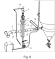
- FIG. 6 shows the cross-flow heat exchanger 1 according to the invention within a process engineering plant.
- the cross-flow heat exchanger 1 has a first metering device 3 in the area of the material inlet 25, with which a uniform filling of the storage container 2 with the material 18 is controlled via the pipe 14.
- a second metering device 11 On the opposite material outlet side 26 there is a second metering device 11, with which the movement of the fixed bed within the process chamber 5 is controlled and the fill level in the storage container 2 is controlled.
- the cross-flow heat exchanger 1 has a pipe 6 on the air inlet side 16, with which a tempered gas 19 with a gas flow 20 is introduced into the air inlet chamber 7. On the opposite air outlet side 17, the gas flow 20 is discharged via a pipe 22.
- the cross-flow heat carrier 1 has a round housing 4.
- the process chamber 5 is located in the housing 4.
- the perforated plate 9 and the sieve 10 are arranged at a distance from each other and form the Process chamber 5, through which the material 18 moves in the direction of arrow 12.
- the perforated plate 9 and the sieve 10 thus have a hollow cylindrical shape, with the material 18 moving through the space between them.
- a hollow cylinder or a hollow cylindrical shape is understood to mean a shape in which a smaller cylinder is cut out of a cylinder. The smaller, cut-out cylinder then forms the free space 27.
- the free space 27 which forms the air inlet side 16.
- the tempered gas 19 is introduced into the free space with a gas flow 20, flows through the perforated plate 9, the process chamber 5, and the sieve 10 and is discharged again from the cross-flow heat exchanger 1 on the air outlet side 17.
Landscapes
- Engineering & Computer Science (AREA)
- Mechanical Engineering (AREA)
- General Engineering & Computer Science (AREA)
- Life Sciences & Earth Sciences (AREA)
- Microbiology (AREA)
- Heat-Exchange Devices With Radiators And Conduit Assemblies (AREA)
Abstract
Querstromwärmetauscher (1) zur thermischen Behandlung von grieß- und/oder granulatförmigen Stoffen (18) bestehend aus einem Gehäuse (4) mit einem oberen Stoffeintritt (25), einer Prozesskammer (5), durch welche sich der Stoff (18) bewegt und einem unteren Stoffaustritt (25), wobei ausgehend von einer Lufteintrittsseite (16) die Prozesskammer (5) mit einem temperierten Gas (19) in Richtung einer Luftaustrittsseite (17) durchströmbar ist, wobei der Querstromwärmetauscher (1) auf der Lufteintrittsseite (16) eine Lufteintrittskammer (7) mit einem Kammergehäuse (13, 13') aufweist, welches einseitig mit einem Lochblech (9) abgeschlossen ist und auf der Luftaustrittsseite (17) eine Luftaustrittskammer (8) mit einem Kammergehäuse (13, 13") aufweist, welches einseitig mit einem Sieb (10) abgeschlossen ist.
Description
- Die Erfindung betriff einen Querstromwärmetauscher zur thermischen Behandlung von grieß- und/oder granulatförmigen Stoffen nach dem Oberbegriff des Anspruches 1.
- Unter einem Wärmetauscher wird eine Vorrichtung verstanden, welche die thermische Energie von einem Stoffstrom auf einen anderen überträgt. Derartige Wärmetauscher werden beispielsweise in verfahrenstechnischen Anlagen eingesetzt und können als Querstromwärmetauscher ausgebildet sein.
- Querstromwärmetauscher führen eine thermische Behandlung von pulvergrieß- und/oder granulatförmigen Stoffen durch. Ein solcher Querstromwärmetauscher befindet sich beispielsweise in einer Recyclinganlage, welche verunreinigtes Schüttgut (z.B. Granulaten) aufbereitet, so dass es in späteren Herstellungs- oder Verarbeitungsprozessen als Ausgangsmaterial für ein neues Produkt verwendet werden kann.
- Der Querstromwärmetauscher besteht üblicherweise aus einer Prozesskammer, durch welche das zu temperierende Granulat in vertikaler Richtung geführt wird. Die Prozesskammer weist seitliche Stutzen auf, durch welche ein Luftstrom in die Prozesskammer eingeleitet wird. Der Luftstrom umströmt das zu temperierende Granulat und tritt auf der gegenüberliegenden Seite aus der Prozesskammer wieder aus.
- Mit der
EP 1 019 663 A1 wird ein Trockner-Wärmetauscher zur thermischen Behandlung körnigen Schüttgütern offenbart. Der Wärmetauscher besteht im Wesentlichen aus einem Gehäuse mit einem Kanal mit luftdurchlässigen Blechen, durch welchen das Schüttgut durchgeleitet wird. Seitlich am Gehäuse befinden sich mehrere Stutzen für den Ein- und Austritt des Prozessgases. Der Aufbau des Trockner-Wärmetauschers ist durch die unterteilte Kammer und die zahlreichen, seitlichen Stutzen sehr aufwändig. Es ist daher schwer die Bewegung des Granulats innerhalb des Kanals zu kontrollieren. Darüber hinaus lässt sich der Innenraum des Wärmetauschers nur bedingt reinigen. - Aufgabe der vorliegenden Erfindung ist es nun einen Querstromwärmetauscher dergestalt auszubilden, dass er einfacher aufgebaut ist, eine effizientere thermische Behandlung durchführt und leichter zu reinigen ist. Darüber hinaus sollte mit dem Querstromwärmetauscher die Bewegung des Granulates besser kontrollierbar sein.
- Zur Lösung der gestellten Aufgabe ist die Erfindung durch die technische Lehre des Anspruches 1 gekennzeichnet.
- Wesentliches Merkmal der Erfindung ist, dass der Querstromwärmetauscher auf der Lufteintrittsseite eine Lufteintrittskammer mit einem Kammergehäuse aufweist, welches einseitig mit einem Lochblech abgeschlossen ist und auf der Luftaustrittsseite eine Luftaustrittskammer mit einem Kammergehäuse aufweist, welches einseitig mit einem Sieb abgeschlossen ist.
- Bei einer ersten bevorzugten Ausführungsform besteht der Querstromwärmetauscher aus einem Gehäuse mit einer Prozesskammer. Das Gehäuse weist einen Stoffeintritt und einen Stoffaustritt für den granulatförmigen Stoff auf. Der granulatförmige Stoff bewegt sich innerhalb der Prozesskammer von oben nach unten und weist vorzugsweise einen Festbett-Zustand auf. Die Prozesskammer wird von einem Gasstrom durchströmt. Der Gasstrom wird über eine Lufteintrittskammer eingeleitet, durchströmt bzw. umströmt den granulatförmigen Stoff und wird über eine Luftaustrittskammer wieder aus der Prozesskammer ausgeleitet.
- Die Lufteintrittskammer und/oder die Luftaustrittskammer sind lösbar an dem Gehäuse des Querstromwärmetauschers angeordnet. Durch die lösbare Anordnung können die Lufteintrittskammer und die Luftaustrittskammer von dem Gehäuse entfernt und leicht gereinigt werden. Des Weiteren ist durch das Abtrennen der Lufteintritts- und/oder Luftaustrittskammer die Prozesskammer freizugänglich und kann ebenfalls leicht gereinigt werden.
- Die Lufteintrittskammer und/oder die Luftaustrittskammer bestehen im Wesentlichen aus einem Kammergehäuse, welches eine Aufnahme für ein Lochblech oder ein Sieb bilden. Vorzugsweise sind das Lochblech und/oder das Sieb lösbar mit der Lufteintrittskammer und/oder Luftaustrittskammer verbunden.
- Das Kammergehäuse ist vorzugsweise kastenförmige oder zylindrisch ausgebildet und einseitig mit einem Lochblech oder einem Sieb abgeschlossen. Das Kammergehäuse weißt somit ein Kammervolumen zur Aufnahme einer bestimmten Menge des temperierten Gases auf, wobei das Gas durch Öffnungen des Lochbleches aus dem Kammergehäuse der Lufteintrittskammer ausströmt und durch Spalte des Siebes in das Kammergehäuse der Luftaustrittskammer einströmt.
- Das Lochblech und/oder das Sieb können einteilig oder mehrteilig ausgebildet sein. Des Weiteren können das Lochblech und das Sieb jede beliebige geometrische Form und Abmessung aufweisen. Entscheidend ist, dass das Lochblech und das Sieb in das Kammergehäuse der Lufteintritts- und Luftaustrittskammer angeordnet werden können.
- Bei einer bevorzugten Ausführungsform weist die Lufteintrittskammer vorzugsweise ein Lochblech auf, welches eine luftdurchlässige Trennung zwischen dem Kammergehäuse der Lufteintrittskammer und der Prozesskammer bildet. Die Anordnung eines Lochblechs auf der Lufteintrittsseite hat den wesentlichen Vorteil, dass das Lochblech einfach aufgebaut und dadurch relativ kostengünstig ist. Das Lochblech muss lediglich luftdurchlässig sein, damit der Gasstrom in die Prozesskammer einströmen kann.
- Das Lochblech weist mehrere luftdurchlässige Öffnungen auf. Vorzugsweise sind die Öffnung dergestalt ausgebildet, dass der Gasstrom, welcher durch die Rohrleitung in die Lufteintrittskammer einströmt, einen gewissen Rückstau bildet und sich über die gesamte Lufteintrittskammer verteilt. Durch die Verteilung des Luftstromes über die gesamte Lufteintrittskammer wird der Gasstrom gleichmäßig an den granulatförmigen Stoff in der Prozesskammer abgeben. Die Lufteintrittskammer ist somit ein Art Verteilelement, welche den Gasstrom gleichmäßig über die gesamte Höhe der Prozesskammer verteilt. Dadurch lässt sich die Bewegung des granulatförmigen Stoffes besser kontrollieren und den Stoff effizienter thermisch behandeln.
- Im Gegensatz hierzu wurde beim Stand der Technik der Gasstrom an mehreren, einzelnen Stellen in die Prozesskammer eingeblasen. Das ist mit dem Nachteil verbunden, dass der granulatförmige Stoff an mehreren Stellen mit dem Gasstrom beaufschlagt wird und dadurch die Bewegung des granulatförmigen Stoffes negativ beeinflusst wird.
- Die Luftaustrittskammer weist vorzugsweise ein Sieb auf, welches den Gasstrom von dem granulatförmigen Stoff trennt. Das Sieb ist beispielsweise als Spaltsieb ausgebildet. Spaltsiebe benötigen einen geringen Bauraum, sind wartungsarm und weisen einen hohen Wirkungsgrad auf. Derartige Spaltensiebe sind nahezu verstopfungsfrei. Die Prozesskammer wird durch die Form des Lochblechs und durch die Form des Siebes gebildet.
- Die Lufteintrittskammer und die Luftaustrittskammer sind jeweils mit Rohrleitungen verbunden, welche den temperierten (erhitzten oder abgekühlten) Gasstrom zu bzw. abführen. Vorzugsweise wird der abgeführte Gasstrom einem weiteren Prozess innerhalb der verfahrenstechnischen Anlage zu geführt.
- Oberhalb des Gehäuses ist auf der Produkteintrittsseite ein Vorlagebehälter für den granulatförmigen Stoff angeordnet. Der Vorlagebehälter wird über eine Förderleitung mit dem Granulat gefüllt. Vorzugsweise befindet sich im Bereich der Förderleitung eine Dossiervorrichtung.
- Der Vorlagebehälter ist beispielsweise fest mit dem Gehäuse des Querstromwärmetauscher verbunden und bildet eine Einheit mit dem Gehäuse aus. Es ist aber auch möglich, dass der Vorlagebehälter als separate Einheit ausgebildet ist, welche lösbar an dem Gehäuse des Querstromwärmetauschers angeordnet ist. Durch die lösbare Verbindung lässt sich der Vorlagebehälter vom Gehäuse entfernen und leicht reinigen.
- Generell ist die Form der Lufteintritt- und/oder die Luftaustrittskammern an die Gehäuseform des Querstromwärmetauschers angepasst. Das Gehäuse des Querstromwärmetauscher ist vorzugsweise eckig ausgebildet und weist beispielsweise eine Rechteckform auf. Die Lufteintritt- und/oder die Luftaustrittskammer sind ebenfalls eckig ausgebildet und an die Gehäuseform des Querstromwärmetauschers angepasst. Es ist jedoch auch möglich, dass das Gehäuse eine zylindrische bzw. runde Form aufweist.
- Bei einer weiteren bevorzugten Ausführungsform sind die Kammergehäuse der Lufteintrittskammer und der Luftaustrittskammer gleich ausgebildet. Dies bedeutet, dass an das Gehäuse des Querstromwärmetauschers sowohl auf der Lufteintrittsseite, als auch auf der Luftaustrittsseite stets das gleiche Kammergehäuse mit den gleichen Abmessungen montiert werden kann. Das Lochblech und das Sieb sind hierbei lösbar mit dem Kammergehäuse verbunden, so dass das Lochblech und/oder das Sieb entweder in das Kammergehäuse der Lufteintrittskammer und/oder der Luftaustrittskammer montiert werden können. Der erfindungsgemäße Querstromwärmetauscher ist somit modular aufgebaut.
- Bei einer weiteren bevorzugten Ausführungsform weist der Querstromwärmetauscher eine Prozesskammer mit der Form eines Kreisringquerschnitts bzw. eines Hohlzylinders auf. Der granulatförmige Stoff wird von oben in die kreisringförmige Prozesskammer eingeleitet und bewegt sich über den gesamten Umfang des Kreisrings nach unten. Der Gasstrom wird entweder von unten und/oder von oben in die (freie) Mitte des Kreisrings eingeleitet, wobei der Gasstrom den granulatförmigen Stoff von innen nach außen durchströmt. Auf der Lufteintrittsseite befindet sich ein kreisringförmiges Lochblech. Auf der Luftaustrittsseite befindet sich ein Sieb, vorzugsweise eine Spaltsieb. Das Lochblech und das Sieb sind beabstandet voneinander angeordnet und bilden die kreisförmige Prozesskammer aus.
- Als weitere Variante ist es möglich, dass die Prozesskammer die Form eines Kreisringquerschnitts bzw. Hohlzylinders aufweist, wobei der Gasstrom die Prozesskammer von außen nach innen durchströmt. Auf der Lufteintrittsseite befindet sich ein kreisringförmiges Lochblech. Auf der Luftaustrittsseite befindet sich ein Sieb, vorzugsweise eine Spaltsieb.
- Das Spaltensieb kann beispielsweise als Siebplatte, gebogenes Spaltsieb, Trommeln oder Zylinder ausgebildet sein.
- Mit der Dossiervorrichtung bzw. den Dossiervorrichtungen findet eine Steuerung des granulatförmigen Stoffes statt, welcher sich innerhalb der Prozesskammer langsam von oben (Stoffeintritt) nach unten (Stoffaustritt) bewegt. Ziel ist es ein Festbett innerhalb der Prozesskammer zu erreichen. Hierbei sollte ein Luftkurzschluss verhindert werden, bei welchem die Luft innerhalb der Prozesskammer entgegen des Bewegungsrichtung des granulatförmigen Stoffes nach oben aufsteigt und dadurch die Bewegungsgeschwindigkeit der einzelnen Granulate verungleichmäßigt.
- Die Dossiervorrichtung ist beispielsweise als Zellenradschleuse, Schieber, Dosierschnecke, Doppelklappe, Absperrung mittels Handrades, Haspelkette, elektropneumatische Absperrung oder dergleichen ausgebildet.
- Bei einer bevorzugten Ausführungsform befindet sich eine Dossiervorrichtung auf der Stoffaustrittsseits des Querstromwärmetauschers. Mit der Dossiervorrichtung wird der kontinuierliche Betrieb des Querstromwärmetauscher gesteuert. Dies bedeutet, dass der granulatförmige Stoff in der Prozesskammer stets als ein Festbett vorliegt, welches von dem Gasstrom bzw. Luftstrom durchströmt wird.
- Bei einer weiteren, bevorzugten Ausführungsform befinden sich jeweils eine Dossiervorrichtung auf der Stoffeintrittsseite und eine Dosiervorrichtung auf der Stoffaustrittsseite. Mit der oberen Dossiervorrichtung auf der Produkteintrittsseite kann die gleichförmige Befüllung des Vorlagebehälters geregelt werden. Gleichzeit kann auch ein Luftkurzschluss verhindert werden. Mit der unteren Dossiervorrichtung wird der Füllstand innerhalb des Vorlagebehälters geregelt. Vorzugsweise sind beide Dossierungsvorrichtungen (oben, unten) mit einer Steuerung verbunden und werden von dieser geregelt. Auf die obere Dossiervorrichtung kann verzichtet werden, wenn ein ausreihend vorhandenes Schüttgutbett oberhalb der Prozesskammer vorliegt.
- Der Vorlagebehälter kann ferner einen Füllstandsmelder aufweisen, welcher den Füllstand des granulatförmigen Stoffes innerhalb des Vorlagebehälter misst und in Abhängigkeit hiervon die obere und/oder untere Dossiervorrichtung steuert.
- Die Lufteintrittskammer ist über eine Rohrleitung mit einer Temperiervorrichtung verbunden. Die Wärmeenergie kann beispielsweise mittels Gasbrenner, Dampferzeuger oder Heißwasser mit Wärmetauscher oder elektrischem Heizregister erzeugt werden. Es kann auch die Abwärme von anderen Prozessschritten beispielsweise über einen Rekuperator genutzt werden.
- Das temperierte Gas können als Heiz- oder Kühlgas ausgebildet sein. Das Gas kann beispielsweise Luft sein.
- Unter einem Stoff wird generell ein grieß- und/oder granulatförmiger Stoff verstanden. Es ist hierbei durchaus möglich, dass der Stoff einen gewissen Anteil an Feuchtigkeit aufweist.
- Der erfindungsgemäße Querstromwärmetauscher ist vorzugsweise Bestandteil einer verfahrenstechnischen Anlage. Beispielsweise kann der Querstromwärmetauscher mit einem Desodorierungssystem kombiniert werden, welches im kontinuierlichen oder diskontinuierlichen Betrieb in einem thermischen Prozess flüchtige organische Verbindungen (VOC) aus den recycelten Kunststoffen entfernt. Dabei wird das Kunststoffgranulat zunächst auf die benötigte Prozesstemperatur erhitzt und anschließend für eine bestimmte Verweilzeit in einem Silo mit Luft durchspült. Die Luft nimmt dabei die flüchtigen Fremdstoffe auf. Die erwärmte Abluft kann als Prozesswärme innerhalb der verfahrenstechnischen Anlage wieder genutzt werden. Dadurch werden insbesondere Energiekosten eingespart.
- Der Erfindungsgegenstand der vorliegenden Erfindung ergibt sich nicht nur aus dem Gegenstand der einzelnen Patentansprüche, sondern auch aus der Kombination der einzelnen Patentansprüche untereinander.
- Alle in den Unterlagen, einschließlich der Zusammenfassung offenbarten Angaben und Merkmale, insbesondere die in den Zeichnungen dargestellte räumliche Ausbildung, werden als erfindungswesentlich beansprucht, soweit sie einzeln oder in Kombination gegenüber dem Stand der Technik neu sind.
- Im Folgenden wird die Erfindung anhand von mehreren Ausführungswegen darstellenden Zeichnungen näher erläutert. Hierbei gehen aus den Zeichnungen und ihrer Beschreibung weitere erfindungswesentliche Merkmale und Vorteile der Erfindung hervor.
- Es zeigen:
- Figur 1:
- schematische Darstellung des Querstromwärmetauschers
- Figur 2:
- schematische Seitenansicht des Querstromwärmetauschers
- Figur 3:
- Explosivdarstellung des Querstromwärmetauschers
- Figur 4:
- Explosivdarstellung des Querstromwärmetauschers in der Draufsicht
- Figur 5:
- Explosivdarstellung des Querstromwärmetauschers mit Verstärkungen
- Figur 6:
- schematische Darstellung des Querstromwärmetauschers innerhalb einer verfahrenstechnischen Anlage
- Figur 7:
- Schnittdarstellung einer weiteren Ausführungsform des Querstromwärmetauschers
- Mit der
Figur 1 wird der Querstromwärmetauscher 1 dargestellt. Der Querstromwärmetauscher 1 besteht aus einem Gehäuse 4, an welches jeweils eine Lufteintrittskammer 7, sowie eine Luftaustrittskammer 8 angeordnet ist. Im Gehäuse 4 befindet sich die Prozesskammer 5. Das Gehäuse 4 ist rechteckig und weist einen Freiraum 27 auf, durch welchen das Gas 19 strömt. Oberhalb des Gehäuses 4 befindet sich im Bereich des Stoffeintritts 25 ein Vorlagebehälter 2, welcher einen Stoff 18 aus einer Förderleitung 14 (sieheFigur 6 ) erhält. Der Vorlagebehälter 2 ist konisch ausgebildet, wodurch sich der Stoff 18 leicht in Richtung der Prozesskammer 5 bewegt. Gleichzeitig wird durch die konische Form des Vorlagebehälter 2 die Gefahr eines Kurzluftschlusses reduziert. - Auf der gegenüberliegenden Seite des Gehäuses 4 befindet sich der Stoffaustritt 26, über welchen der Stoff 18 aus dem Querstromwärmetauscher 1 ausgeleitet wird. Der Vorlagebehälter 2 dient als Vorratsbehälter für den Querstromwärmetauscher 1 und sorgt dafür, dass sich stets eine ausreichende Menge des Stoffes 18 in der Prozesskammer 5 befindet.
- Das Gehäuse 4 des Querstromwärmetauschers 1 bildet die Basis für die beiden Lufteintritt- und Luftaustrittskammern 7, 8, welche lösbar am Gehäuse 4 angeordnet sind. Das Kammergehäuse 13 der Lufteintritt- und Luftaustrittskammer 7, 8 ist identisch ausgebildet. Auf der Lufteintrittsseite 16 weist die Lufteintrittskammer 7 einen Stutzen 23 für den Anschluss einer Rohrleitung 6 auf. Über die Rohrleitung 6 wird das temperierte Gas 19 in das Kammergehäuse 13 der Lufteintrittskammer 7 eingeleitet. Auf der Luftaustrittsseite 17 weist die Luftaustrittskammer 8 einen Stutzen 24 für den Anschluss einer Rohrleitung 22 auf. Über die Rohrleitung 22 wird das Gas 19 aus dem Kammergehäuse 13 der Lufteintrittskammer 8 ausgeleitet.
-
Figur 2 zeigt den Querstromwärmetauscher 1 mit einer Seitenansicht. Der Querstromwärmetauscher 1 ist relativ kompakt und einfach aufgebaut. Auf der Lufteintrittsseite 16 befindet sich eine Lufteintrittskammer 7 mit nur einem Stutzen 23. Auf der Lufteintrittsseite 17 befindet sich eine Lufteintrittskammer 8 mit ebenfalls nur einem Stutzen 24. -
Figur 3 zeigt den Querstromwärmetauscher 1 mit einer Explosionsdarstellung. Der Querstromwärmetauscher 1 besteht im Wesentlichen aus einem Gehäuse 4, einer Lufteintrittskammer 7 und einer Luftaustrittskammer 8. Oberhalb des Gehäuses 4 ist ein Vorlagebehälter 2 vorhanden. - Die Lufteintrittskammer 7 besteht aus einem Kammergehäuse 13, in welches ein Lochblech 9 eingesetzt wird. Die Luftaustrittskammer 8 besteht ebenfalls aus einem Kammergehäuse 13, in welches ein Sieb 10 eingesetzt wird. Das Lochblech 9 und das Sieb 10 sind lösbar mit den Kammergehäusen 13 verbunden.
- Die Kammergehäuse 13 der Lufteintrittskammer 7 und der Luftaustrittskammer 8 sind vorzugsweise identisch ausgebildet, wodurch der Aufbau des Querstromwärmetauscher 1 relativ einfach ist und kostengünstig hergestellt werden kann. Die Kammergehäuse 13, 13' 13" sind kastenförmig ausgebildet und können dadurch ein gewisses Volumen des Gas 19 bzw. des Gasstromes 20 aufnehmen. Das Lochblech 9 und das Sieb 10 schließend jeweils einseitig des Kammergehäuse 13, 13,', 13" ab. Im zusammengebauten Zustand ist der Kammergehäuse 13, 13', 13" geschlossen, wobei der Gasstrom 20 nur noch durch die Öffnungen des Lochbleches 9 aus dem Kammergehäuse 13, 13' ausströmen und durch die Spalte des Siebes 10 in das Kammergehäuse 13, 13" einströmen kann.
- Im zusammengebauten Zustand ist das Lochblech 9 und das Sieb 10 beabstandet voneinander angeordnet und bilden in dem Zwischenraum die Prozesskammer 5 für den Stoff 18 aus.
- Gemäß der
Figur 3 ist das Sieb 10 als Spaltsieb ausgebildet. Die Öffnungen des Spaltsiebes 10 sind hierbei so ausgestaltet, dass der Stoff 18 zurückgehalten wird und Gas 19 mit einem Gasstrom 20 durchströmen kann. -
Figur 4 zeigt eine Draufsicht auf den Querstromwärmetauscher 1. Auf der Lufteintrittsseite 16 befindet sich die Lufteintrittskammer 7 mit dem Lochblech 9. Auf der Luftaustrittsseite 8 befindet sich die Luftaustrittskammer 8 mit dem Sieb 10. Beide Bauteile 7, 8 werden an das Gehäuse 4 montiert und bilden die Prozesskammer 5 aus. - Mit der
Figur 5 werden die einzelnen Komponenten des Querstromwärmetauschers 1, sowie der Gasstrom 20 des Gases 19 innerhalb des Querstromwärmetauschers 1 dargestellt. - Das Gasstrom 20 wird auf der Lufteintrittsseite 16 in das Kammergehäuse 13' eingeleitet und trifft dort auf das Lochblech 9. Das Lochblech 9 ist dergestalt ausgebildet, dass sich der Gasstrom 20 innerhalb des Kammergehäuses 13' rückstaut, wodurch eine homogene Verteilung des Gasstromes 20 bewirkt wird. Der Gasstrom 20 wird somit in dem Kammergehäuse 13'verteilt und über die gesamte Höhe der Prozesskammer 5 abgegeben. Durch das Verteilen des Gasstromes 20 auf der Lufteintrittsseite 16 wird eine gleichmäßige Durchströmung der Prozesskammer 5 des Querstromwärmetauschers 1 erreicht. Die Bewegung des Stoffes 18 von oben nach unten innerhalb der Prozesskammer 5 wird somit nicht von dem Gasstrom 20 gestört. Dadurch wird stets ein Festbett aufrechterhalten.
- Auf der gegenüberliegenden Luftaustrittsseite 17 befindet sich das die Luftaustrittskammer 8 mit dem Kammergehäuse 13" und dem Sieb 10. Nach dem Durchströmen des Gases 19 durch die Prozesskammer 5 trifft der Gasstrom 20 zunächst auf das Sieb 10, welches das Gas 19 vom Stoff 18 trennt. Der Gasstrom 20 wird danach von dem Kammergehäuse 13" zusammengeführt und durch eine Rohrleitung 22 ausgeleitet. Die Kammergehäuse 13, 13',13" wirken demnach als Verteilelement bzw. Auffangelement für das temperierte Gas 19.
- Gemäß der
Figur 5 weist das Gehäuse 4 des Querstromwärmetauscher 1 zahlreiche Verstärkungen 21 auf. Die Verstärkungen 21 dienen als Stützen bzw. Haltevorrichtungen für das Lochblech 9 bzw. das Sieb 10. -
Figur 6 zeigt den erfindungsgemäßen Querstromwärmetauscher 1 innerhalb einer verfahrenstechnischen Anlage. Der Querstromwärmetauscher 1 weist im Bereich des Stoffeintritts 25 eine erste Dosiervorrichtung 3 auf, mit welcher ein gleichmäßiges Befüllen des Vorlagebehälters 2 mit dem Stoff 18 über die Rohrleitung 14 kontrolliert wird. Auf der gegenüberliegenden Stoffaustrittsseite 26 befindet sich eine zweite Dosiervorrichtung 11, mit welcher die Bewegung des Festbetts innerhalb der Prozesskammer 5 gesteuert und der Füllstand im Vorlagebehälter 2 kontrolliert werden. - Der Querstromwärmetauscher 1 weist auf der Lufteintrittsseite 16 eine Rohrleitung 6 auf, mit welcher ein temperiertes Gas 19 mit einem Gasstrom 20 in die Lufteintrittskammer 7 eingeleitet wird. Auf der gegenüberliegenden Luftaustrittseite 17 wird der Gasstrom 20 über eine Rohrleitung 22 ausgeleitet.
- Mit der
Figur 7 wird eine weitere Ausführungsform des Querstromwärmeträgers 1 gezeigt. Der Querstromwärmeträger 1 weist ein rundes Gehäuse 4 auf. Im Gehäuse 4 befindet sich die Prozesskammer 5. Das Lochblech 9 und das Sieb 10 sind beabstandet voneinander angeordnet und bilden zwischen sich die Prozesskammer 5, durch welche sich der Stoff 18 in Pfeilrichtung 12 bewegt. Das Lochblech 9 und das Sieb 10 weisen somit eine hohlzylindrische Form auf, wobei sich der Stoff 18 durch den Zwischenraum bewegt. Unter einem Hohlzylinder bzw. einer hohlzylindrischen Form wird eine Form verstanden, bei welcher aus einem Zylinder ein kleinerer Zylinder herausgeschnitten wird. Der kleinere, herausgeschnittene Zylinder bildet dann den Freiraum 27. - In der Mitte des Hohlzylinders ist der Freiraum 27, welcher die Lufteintrittsseite 16 bildet. Das temperierte Gas 19 wird mit einem Gasstrom 20 in den Freiraum eingeleitet, durchströmt das Lochblech 9, die Prozesskammer 5, sowie das Sieb 10 und wird auf der Luftaustrittsseite 17 wieder aus dem Querstromwärmetauscher 1 ausgeleitet.
-
- 1.
- Querstromwärmetauscher
- 2.
- Vorlagebehälter
- 3.
- Dossiervorrichtung (oben)
- 4.
- Gehäuse
- 5.
- Prozesskammer
- 6.
- Rohrleitung von 16
- 7.
- Lufteintrittskammer
- 8.
- Luftaustrittskammer
- 9.
- Lochblech
- 10.
- Sieb
- 11.
- Dossiervorrichtung (unten)
- 12.
- Pfeilrichtung
- 13.
- Kammergehäuse von 7, 8
- 14.
- Förderleitung
- 15.
- Förderleitung
- 16.
- Lufteintrittsseite
- 17.
- Luftaustrittseite
- 18.
- Stoff
- 20.
- Gas
- 21.
- Verstärkung
- 22.
- Rohrleitung von 17
- 23.
- Stutzen von 16
- 24.
- Stutzen von 17
- 25.
- Stoffeintritt
- 26.
- Stoffaustritt
- 27.
- Freiraum
Claims (15)
- Querstromwärmetauscher (1) zur thermischen Behandlung von grieß- und/oder granulatförmigen Stoffen (18) bestehend aus einem Gehäuse (4) mit einem oberen Stoffeintritt (25), einer Prozesskammer (5), durch welche sich der Stoff (18) bewegt und einem unteren Stoffaustritt (26), wobei ausgehend von einer Lufteintrittsseite (16) die Prozesskammer (5) mit einem temperierten Gas (19) in Richtung einer Luftaustrittsseite (17) durchströmbar ist, dadurch gekennzeichnet, dass der Querstromwärmetauscher (1) auf der Lufteintrittsseite (16) eine Lufteintrittskammer (7) mit einem Kammergehäuse (13, 13', 13") aufweist, welches einseitig mit einem Lochblech (9) abgeschlossen ist und auf der Luftaustrittsseite (17) eine Luftaustrittskammer (8) mit einem Kammergehäuse (13, 13', 13") aufweist, welches einseitig mit einem Sieb (10) abgeschlossen ist.
- Querstromwärmetauscher (1) nach Anspruch 1, dadurch gekennzeichnet, dass die Lufteintrittskammer (7) und die Luftaustrittskammer (8) lösbar mit dem Querstromwärmetauscher (1) verbunden sind.
- Querstromwärmetauscher (1) nach Anspruch 1 oder 2, dadurch gekennzeichnet, dass das Lochblech (9) und/oder das Sieb (10) lösbar mit dem Kammergehäuse (13, 13', 13") verbunden sind.
- Querstromwärmetauscher (1) nach einem der Ansprüche 1 bis 3, dadurch gekennzeichnet, dass die Kammergehäuse 13, 13', 13" durch das Lochblech (9) oder das Sieb (10) abgeschlossen sind, wobei das Gas (19) durch Öffnungen des Lochbleches (9) aus dem Kammergehäuse 13, 13' ausströmt und durch Spalte des Siebes (10) in das Kammergehäuse (13, 13") einströmt.
- Querstromwärmetauscher (1) nach einem der Ansprüche 1 bis 4, dadurch gekennzeichnet, dass das Sieb (10) als Spaltsieb ausgebildet ist.
- Querstromwärmetauscher (1) nach einem der Ansprüche 1 bis 5, dadurch gekennzeichnet, dass das Lochblech (9) und das Sieb (10) beabstandet voneinander am Gehäuse (4) angeordnet sind und zwischen sich die Prozesskammer (5) bilden, durch welche sich der Stoff (18) als Festbett bewegt.
- Querstromwärmetauscher (1) nach einem der Ansprüche 1 bis 6, dadurch gekennzeichnet, dass der Querstromwärmetauscher (1) im Bereich des Stoffeintritts (25) einen Vorlagebehälter (2) als Vorratsbehälter für den Stoff (18) aufweist.
- Querstromwärmetauscher (1) nach einem der Ansprüche 1 bis 7, dadurch gekennzeichnet, dass der Querstromwärmetauscher (1) im Bereich des Stoffaustritts (26) eine Dossiervorrichtung (11) aufweist..
- Querstromwärmetauscher (1) nach einem der Ansprüche 8 oder 9, dadurch gekennzeichnet, dass die Dossiervorrichtung (3, 11) als Zellenradschleuse ausgebildet ist.
- Querstromwärmetauscher (1) nach einem der Ansprüche 1 bis 9, dadurch gekennzeichnet, dass der Querstromwärmetauscher (1) im Bereich des Stoffeintritts (25) eine Dossiervorrichtung (3) und im Bereich des Stoffaustritts (26) eine Dossiervorrichtung (11) aufweist, wobei eine Steuerung die beiden Dossiervorrichtungen (3, 11) dergestalt steuert, dass der Stoff (18) in der Prozesskammer (5) stets als Festbett vorliegt.
- Querstromwärmetauscher (1) nach einem der Ansprüche 1 bis 10, dadurch gekennzeichnet, dass ein Füllstandmesser den Füllstand des Stoffes (18) im Vorlagebehälter (2) misst, wobei eine Steuerung in Abhängigkeit von dem Füllstand mindestens eine Dossiervorrichtung (3, 11) steuert
- Querstromwärmetauscher (1) nach einem der Ansprüche 8 bis 11, dadurch gekennzeichnet, dass das Kammergehäuse (13, 13', 13") ein Kammervolumen zur Aufnahme einer bestimmten Menge des temperierten Gases (19) aufweist.
- Querstromwärmetauscher (1) nach einem der Ansprüche 1 bis 12, dadurch gekennzeichnet, dass das Lochblech (9) eine homogene Verteilung des Gases (19) innerhalb des Kammergehäuses (13, 13') bewirkt und dadurch das Gas (19) mit einem gleichmäßigen Gasstrom (20) durch die Prozesskammer (5) strömt.
- Querstromwärmetauscher (1) nach einem der Ansprüche 1 bis 13, dadurch gekennzeichnet, dass das Lochblech (9) und das Sieb (10) eine eckige oder runde Form aufweisen.
- Querstromwärmetauscher (1) nach einem der Ansprüche 1 bis 13, dadurch gekennzeichnet, dass das Lochblech (9) und das Sieb (10) die Form eines Hohlzylinders aufweisen, wobei das Lochblech (9) und das Sieb (10) beabstandet voneinander angeordnet sind und zwischen sich die Prozesskammer (5) bilden und dass der Gasstrom (20) des Gases (19) ausgehend von der Mitte des Hohlzylinders durch das Lochblech (9), den Stoff 18, sowie das Sieb (10) strömt.
Priority Applications (2)
| Application Number | Priority Date | Filing Date | Title |
|---|---|---|---|
| EP22200873.2A EP4354060A1 (de) | 2022-10-11 | 2022-10-11 | Querstromwärmetauscher zur thermischen behandlung von granulatförmigen stoffen |
| PCT/EP2023/078240 WO2024079208A1 (de) | 2022-10-11 | 2023-10-11 | QUERSTROMWÄRMETAUSCHER ZUR THERMISCHEN BEHANDLUNG VON GRIEß- UND/ODER GRANULATFÖRMIGEN STOFFEN |
Applications Claiming Priority (1)
| Application Number | Priority Date | Filing Date | Title |
|---|---|---|---|
| EP22200873.2A EP4354060A1 (de) | 2022-10-11 | 2022-10-11 | Querstromwärmetauscher zur thermischen behandlung von granulatförmigen stoffen |
Publications (1)
| Publication Number | Publication Date |
|---|---|
| EP4354060A1 true EP4354060A1 (de) | 2024-04-17 |
Family
ID=83690284
Family Applications (1)
| Application Number | Title | Priority Date | Filing Date |
|---|---|---|---|
| EP22200873.2A Pending EP4354060A1 (de) | 2022-10-11 | 2022-10-11 | Querstromwärmetauscher zur thermischen behandlung von granulatförmigen stoffen |
Country Status (2)
| Country | Link |
|---|---|
| EP (1) | EP4354060A1 (de) |
| WO (1) | WO2024079208A1 (de) |
Citations (5)
| Publication number | Priority date | Publication date | Assignee | Title |
|---|---|---|---|---|
| DE1067372B (de) * | 1952-09-03 | 1959-10-15 | Zander & Ingestroem | Verfahren zum Trocknen von Getreide |
| US4424634A (en) * | 1981-06-19 | 1984-01-10 | Westelaken C | Modular column dryer for particulate material |
| US5762010A (en) * | 1994-06-21 | 1998-06-09 | Groep Danis, Naamloze Vennootschap | Method and device for processing waste having a calorific value |
| EP1019663A1 (de) | 1997-10-01 | 2000-07-19 | Bühler Ag | Trockner-wärmetauscher |
| DE102013108361A1 (de) * | 2013-08-02 | 2015-02-05 | ATEF.ONE GmbH | Vorrichtung, Anlage und Verfahren zur Trocknung von biologischem Schüttgut, insbesondere Hopfen |
-
2022
- 2022-10-11 EP EP22200873.2A patent/EP4354060A1/de active Pending
-
2023
- 2023-10-11 WO PCT/EP2023/078240 patent/WO2024079208A1/de unknown
Patent Citations (5)
| Publication number | Priority date | Publication date | Assignee | Title |
|---|---|---|---|---|
| DE1067372B (de) * | 1952-09-03 | 1959-10-15 | Zander & Ingestroem | Verfahren zum Trocknen von Getreide |
| US4424634A (en) * | 1981-06-19 | 1984-01-10 | Westelaken C | Modular column dryer for particulate material |
| US5762010A (en) * | 1994-06-21 | 1998-06-09 | Groep Danis, Naamloze Vennootschap | Method and device for processing waste having a calorific value |
| EP1019663A1 (de) | 1997-10-01 | 2000-07-19 | Bühler Ag | Trockner-wärmetauscher |
| DE102013108361A1 (de) * | 2013-08-02 | 2015-02-05 | ATEF.ONE GmbH | Vorrichtung, Anlage und Verfahren zur Trocknung von biologischem Schüttgut, insbesondere Hopfen |
Also Published As
| Publication number | Publication date |
|---|---|
| WO2024079208A1 (de) | 2024-04-18 |
Similar Documents
| Publication | Publication Date | Title |
|---|---|---|
| EP0376356A1 (de) | Verfahren und Vorrichtung zum Abtrennen unerwünschter Bestandteile aus einem Abgas | |
| CH631648A5 (de) | Verfahren und vorrichtung zum kristallisieren von kunststoffgranulat. | |
| DE4118433C2 (de) | Fließbettapparatur zum Behandeln partikelförmigen Gutes | |
| EP0078960B1 (de) | Verfahren und Vorrichtung zum Beleimen von teilchenförmigem Gut,. insbesondere von Spänen | |
| EP0270531B2 (de) | Wanderbettreaktor | |
| DE19957641C1 (de) | Filtermembranmodul mit integriertem Wärmetauscher | |
| EP1019663B1 (de) | Trockner-wärmetauscher | |
| CH640748A5 (de) | Fuellkoerper zum einsatz in einem verfahrenstechnischen apparat und verwendung desselben. | |
| EP4354060A1 (de) | Querstromwärmetauscher zur thermischen behandlung von granulatförmigen stoffen | |
| DE102021206089A1 (de) | Vorrichtung zur Aufbereitung von Wasser | |
| DE2055293A1 (de) | Verfahren und Vorrichtung zur Kontakt aufnahme zwischen verschiedenen Medien | |
| DE202007018534U1 (de) | Vorrichtung zum Trocknen von Granulaten oder Pellets | |
| EP0089486B1 (de) | Wirbelzellenkolonne | |
| CH620984A5 (de) | ||
| EP3308941B1 (de) | Vorrichtung und verfahren zur filtration von kunststoffschmelze | |
| CH630948A5 (de) | Anlage zur russherstellung. | |
| DE202017105534U1 (de) | Doppelrohrbelüftungselement und Belüftungsanlage | |
| DE3422045A1 (de) | Verfahren und biofiltereinrichtung zur biologischen abluftreinigung | |
| DE2608712C2 (de) | Vorrichtung zur Behandlung von körnigen Festgut mit fließfähigen Medien | |
| EP0476300B1 (de) | Verfahren und Vorrichtung zur Adsorption bzw. Chemiesorption von gasförmigen Bestandteilen aus einem Gasstrom | |
| EP0247235B1 (de) | Druckluftförder- und Dosiereinrichtung | |
| DE4413400B4 (de) | Vorrichtung zum Desinfizieren von Luft | |
| DE3116876A1 (de) | Anordnung zum belueften von zu reinigendem abwasser | |
| EP3872053B1 (de) | Extraktionsvorrichtung und extraktionsverfahren für ein fermentationsmedium | |
| WO2017001465A1 (de) | Kontinuierlicher mehrkammerprozess |
Legal Events
| Date | Code | Title | Description |
|---|---|---|---|
| PUAI | Public reference made under article 153(3) epc to a published international application that has entered the european phase |
Free format text: ORIGINAL CODE: 0009012 |
|
| STAA | Information on the status of an ep patent application or granted ep patent |
Free format text: STATUS: THE APPLICATION HAS BEEN PUBLISHED |
|
| AK | Designated contracting states |
Kind code of ref document: A1 Designated state(s): AL AT BE BG CH CY CZ DE DK EE ES FI FR GB GR HR HU IE IS IT LI LT LU LV MC ME MK MT NL NO PL PT RO RS SE SI SK SM TR |